EP1620705B1 - Verfahren zur prüfung der dichtheit von hohlräume enthaltenden bauteilen - Google Patents
Verfahren zur prüfung der dichtheit von hohlräume enthaltenden bauteilen Download PDFInfo
- Publication number
- EP1620705B1 EP1620705B1 EP04730154A EP04730154A EP1620705B1 EP 1620705 B1 EP1620705 B1 EP 1620705B1 EP 04730154 A EP04730154 A EP 04730154A EP 04730154 A EP04730154 A EP 04730154A EP 1620705 B1 EP1620705 B1 EP 1620705B1
- Authority
- EP
- European Patent Office
- Prior art keywords
- component
- tested
- testing
- area
- liquid
- Prior art date
- Legal status (The legal status is an assumption and is not a legal conclusion. Google has not performed a legal analysis and makes no representation as to the accuracy of the status listed.)
- Expired - Lifetime
Links
- 238000012360 testing method Methods 0.000 title claims abstract description 82
- 238000000034 method Methods 0.000 title claims abstract description 35
- 239000007788 liquid Substances 0.000 claims abstract description 65
- XLYOFNOQVPJJNP-UHFFFAOYSA-N water Substances O XLYOFNOQVPJJNP-UHFFFAOYSA-N 0.000 claims abstract description 10
- 230000015572 biosynthetic process Effects 0.000 claims abstract 4
- 238000001816 cooling Methods 0.000 claims description 12
- 238000005406 washing Methods 0.000 claims description 7
- 238000010792 warming Methods 0.000 claims description 2
- 230000001680 brushing effect Effects 0.000 claims 1
- 230000001747 exhibiting effect Effects 0.000 claims 1
- 238000005507 spraying Methods 0.000 claims 1
- LFQSCWFLJHTTHZ-UHFFFAOYSA-N Ethanol Chemical compound CCO LFQSCWFLJHTTHZ-UHFFFAOYSA-N 0.000 abstract description 2
- 239000006260 foam Substances 0.000 abstract description 2
- 239000004094 surface-active agent Substances 0.000 abstract description 2
- 239000012752 auxiliary agent Substances 0.000 abstract 1
- 238000010438 heat treatment Methods 0.000 description 10
- 238000009736 wetting Methods 0.000 description 8
- 239000002131 composite material Substances 0.000 description 7
- 238000010998 test method Methods 0.000 description 5
- 230000007547 defect Effects 0.000 description 4
- 230000008569 process Effects 0.000 description 4
- PEDCQBHIVMGVHV-UHFFFAOYSA-N Glycerine Chemical compound OCC(O)CO PEDCQBHIVMGVHV-UHFFFAOYSA-N 0.000 description 3
- 238000007598 dipping method Methods 0.000 description 3
- 238000007654 immersion Methods 0.000 description 3
- 230000008439 repair process Effects 0.000 description 3
- 230000000630 rising effect Effects 0.000 description 3
- 230000004888 barrier function Effects 0.000 description 2
- 239000000203 mixture Substances 0.000 description 2
- 239000000546 pharmaceutical excipient Substances 0.000 description 2
- 238000002604 ultrasonography Methods 0.000 description 2
- 229920000049 Carbon (fiber) Polymers 0.000 description 1
- 239000002671 adjuvant Substances 0.000 description 1
- 150000001298 alcohols Chemical class 0.000 description 1
- 125000000129 anionic group Chemical group 0.000 description 1
- 239000003945 anionic surfactant Substances 0.000 description 1
- 230000008901 benefit Effects 0.000 description 1
- 239000004917 carbon fiber Substances 0.000 description 1
- 125000002091 cationic group Chemical group 0.000 description 1
- 239000003093 cationic surfactant Substances 0.000 description 1
- 238000004140 cleaning Methods 0.000 description 1
- 238000001514 detection method Methods 0.000 description 1
- 238000001035 drying Methods 0.000 description 1
- 238000005516 engineering process Methods 0.000 description 1
- 239000004744 fabric Substances 0.000 description 1
- 238000005187 foaming Methods 0.000 description 1
- 239000003205 fragrance Substances 0.000 description 1
- 229910052736 halogen Inorganic materials 0.000 description 1
- 150000002367 halogens Chemical class 0.000 description 1
- 230000036541 health Effects 0.000 description 1
- 230000004807 localization Effects 0.000 description 1
- 239000000463 material Substances 0.000 description 1
- VNWKTOKETHGBQD-UHFFFAOYSA-N methane Chemical compound C VNWKTOKETHGBQD-UHFFFAOYSA-N 0.000 description 1
- 239000002736 nonionic surfactant Substances 0.000 description 1
- 239000000049 pigment Substances 0.000 description 1
- 238000003672 processing method Methods 0.000 description 1
- 238000003908 quality control method Methods 0.000 description 1
- 230000005855 radiation Effects 0.000 description 1
- 238000013102 re-test Methods 0.000 description 1
- 239000008149 soap solution Substances 0.000 description 1
- 239000011800 void material Substances 0.000 description 1
Images



Classifications
-
- G—PHYSICS
- G01—MEASURING; TESTING
- G01M—TESTING STATIC OR DYNAMIC BALANCE OF MACHINES OR STRUCTURES; TESTING OF STRUCTURES OR APPARATUS, NOT OTHERWISE PROVIDED FOR
- G01M3/00—Investigating fluid-tightness of structures
- G01M3/02—Investigating fluid-tightness of structures by using fluid or vacuum
- G01M3/04—Investigating fluid-tightness of structures by using fluid or vacuum by detecting the presence of fluid at the leakage point
- G01M3/12—Investigating fluid-tightness of structures by using fluid or vacuum by detecting the presence of fluid at the leakage point by observing elastic covers or coatings, e.g. soapy water
Definitions
- the invention relates to a method for testing the tightness of components containing cavities, wherein at least on one side of the component to be tested at least the surface to be tested is completely wetted with a foam-forming test liquid.
- the subject method and the test liquid can be applied to a variety of components containing cavities.
- plastic composite components with lightweight cores in the form of honeycomb components are used in particular in aircraft technology.
- Such components have a particularly low weight and at the same time particularly good strength properties.
- gas is introduced into the interior of the fuselage and scanned the outer shell by means of a gas sensor.
- a gas sensor Such a method is described, for example, in US Pat. No. 4,976,136.
- this method is particularly complicated and is mainly suitable for enclosed spaces into which the gas can be introduced.
- DD 140 172 A describes a method for finding leaks by means of foaming in which pressurized facilities, in particular telecommunications cables, are provided with a soap solution and any leaks can be detected by the resulting Schaumberg.
- the process requires that the interior of the body to be tested in a given case, the interior of a telecommunications cable to the environment is under pressure. This is in leak tests of some components, such as e.g. Plastic composite components with lightweight cores not possible.
- CA 2 148 844 A shows a method and a device for checking the tightness of air barriers in buildings, wherein a kind of suction cup is slipped over the surface of the air barrier to be tested and a negative pressure is generated by means of a ventilator.
- the surface to be tested is coated with a foam-forming material, which can be detected due to blistering leaks optically.
- JP 57 054832 A describes such a dipping method for checking the tightness of components, which is very complicated to handle and, in particular, does not allow fast and reliable identification of the defects in large components. Moreover, the heating of a water bath is particularly energy and time consuming.
- the object of the present invention is to provide a method for testing the tightness of components containing cavities, in particular plastic composite components with honeycomb cores, which is as quick and easy to carry out, and in which the component to be tested is influenced as little as possible. Furthermore, with the method according to the invention, only parts of the components can be tested for tightness and not the leakproofness of the entire component must be checked. Furthermore, the method should enable a fast, secure and accurate identification of the defects.
- the object of the invention is achieved, on the one hand, by at least cooling the surface of the component to be tested prior to wetting with the test liquid, exposing the component to an increase in temperature, and then checking the surface of the component to be tested for blistering of the test liquid.
- a faster and easier leak test is possible in the subject test method. Since the component to be tested is not underwater, a faster, safer and more accurate identification of the flaws and as a result a simple marking of the same possible.
- it is not necessary to check the entire component for leaks but only the surface of the component containing the flaw needs to be rechecked.
- the component to be tested is influenced much less by the application of the test liquid than is the case when the component is immersed in a water basin.
- This is achieved in that at least the surface to be tested of the component cooled before wetting with the test liquid and the required increase in temperature achieved only by the independent heating of the component to room temperature possibly supported by heat sources.
- the cooling of the surface to be tested of the component or the entire component can be done by any cooling devices, cooling chambers or cooling tunnels through which the component is passed.
- At least the surface of the component to be tested can also be heated after the wetting with the test liquid. By this warming required for the leak test temperature increase is achieved.
- the object according to the invention by at least heating the surface of the component to be tested by irradiation from the side of the component to be tested opposite the surface to be tested, and then checking the surface of the component to be tested for blistering of the test liquid.
- a halogen lamp at a certain distance of some Centimeters are positioned at the rear of the component to be tested.
- At least the surface to be tested of the component can be heated by infrared radiation.
- the heating is preferably carried out to a maximum of 80 ° C.
- the variant of the cooling of the component prior to wetting with the test liquid is particularly advantageous for more complex components in which the heating by means of a lamp or other heat sources from the back of the component would not or not easily possible.
- simultaneous examination of both surfaces of the component is easier than in the method of heating by means of a lamp or the like.
- the opposite sides of at least the surface of the component to be tested are wetted with the test liquid. This makes it possible to simultaneously check both surfaces of the component or the part of the component to be tested.
- the spots with blistering are marked after their identification to facilitate subsequent repair of the component.
- the marking can be done manually but also automatically.
- the surface to be inspected can be scanned, for example, by means of a camera and the blistering can be detected by means of an image processing method, and then the marking can be applied at the appropriate location, for example with a robotic arm or the like.
- test liquid can be spread or sprayed onto at least the surface of the component to be tested or even on all surfaces of the component. It is also possible that the component to be tested is passed through a curtain formed by flowing down test liquid.
- the respective method for applying the test liquid must also be adapted to the shape of the component to be tested or the surface of the component to be tested.
- test liquid is washed off, preferably with water. This washing process is preferably carried out in an automatic washing line.
- This mechanical support can be realized, for example, by brushes, sponges or the like.
- the test liquid for use in testing the leaktightness of void-containing components preferably contains 10% to 20% dissolved surfactants, 2% to 6% alcohol and 75% to 88% water. The given percentages are volume percentages.
- the stated composition of the test liquid causes complete wetting, i. a closed film that reaches the test liquid on the surface of the component to be tested.
- such a test liquid is particularly easy and residue-free washable and does not affect the surface of the component to be tested.
- such a test liquid is not harmful to health and harmful to the environment, so that disposal via the public sewer system is possible.
- the Dichtheitsprüf crackkeit the specified type can be particularly easily applied, in particular by machine, and does not foam in the application.
- the test liquid is suitable for use in temperature ranges between -30 ° C and 80 ° C. In addition, a repetition of the test method after drying of the test liquid is possible because the specified test liquid does not cause closure of a possible leak.
- composition a surface tension of the test liquid is achieved, which allows the bubbles formed remain as long as possible over the leak and little or no coincidence. This should be possible in particular on vertical surfaces of the components to be tested.
- auxiliaries may be included in the leak test liquid. With the help of such excipients, various properties can be achieved.
- anionic, cationic or nonionic surfactants may be included.
- color pigments may be included as an excipient in the test liquid. The color is selected depending on the color of the surface of the component to be tested.
- fragrances may be included as an adjuvant.
- the component 1a and 1b show schematically a leakage test method according to the prior art, wherein the component to be tested 1 in a container 2 with a liquid 3, in particular water, is introduced.
- the component to be tested 1 is present the immersion process at room temperature and is then completely immersed in the liquid 3, which was heated to, for example, 70 ° C according to FIG. 1b.
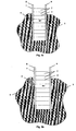
- FIGS. 3 a and 3 b a part of the component to be tested is shown in a sectional representation.
- the component 1 consists for example of a lightweight core 4, in particular a honeycomb core, and on both sides arranged cover layers 5, 6, for example, so-called. Prepreg layers of impregnated carbon fiber fabric.
- the lightweight core 4 contains hollow chambers 7, in which air is usually located.
- the rising of the air bubbles 9 is observed and identified and either under water with a corresponding waterproof pin or the like. marked or marked only after the removal of the component 1 from the basin 2. Due to the rising air bubbles 9 a precise identification of the leak 8 is usually not possible. In addition, it is always necessary, even with repeated leak tests of the component 1, to immerse the entire component 1 completely in the liquid 3 in the container 2.
- FIGS. 2a and 2b show schematically a variant of the method according to the invention, wherein the component 1 is wetted at least on the surface to be tested with a test liquid and then the component 1 is subjected to a temperature increase.
- This temperature increase from room temperature, for example, to 80 ° C, can be done with a lamp 10 which irradiates the component 1 from the back of the surface to be tested and heated accordingly. Due to the heating of the surface to be tested of the component 1, there is an expansion of the air contained in the high chambers 7 and any leakage through leaks, which is due to the applied test liquid to blistering and thus a clear and reliable identification of the defects becomes possible.
- FIGS. 4a and 4b show a part of the component to be tested 1 in a sectional illustration using the method according to the invention according to FIGS. 2a and 2b.
- the surface of the cover layer 5 of the component 1 is completely wetted with a film of the test liquid 11.
- the component 1 is heated to a temperature which is sufficient that the air contained in the cavities 7 is expanded to such an extent that it escapes via any leaks 8 in the component 1.
- the escaping air forms bubbles 12 from the test liquid 11.
- a significant advantage of the present method is that not the entire component 1 must be immersed in a liquid, but only the surface to be tested with a test liquid 11 must be wetted and the component. 1 a temperature increase must be suspended.
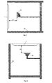
- FIGS. 5 and 6 show two process arrangements in which the component 1 to be tested is heated with a lamp 10, which is located at a distance D from the component 1.
- the lamp 10 may be fixed from a frame 13 and also be movable, so that the whole component 1 can be scanned by the lamp 10.
- the component 1 can also be cooled prior to wetting with the test liquid 11 and, after wetting with the test liquid 11, only heated to room temperature, whereby the in The air contained in the hollow chambers 7 of the component 1 expands and escapes via any leaks 8.
- a test method is done automatically by the components to be tested 1 are passed through appropriate cooling or heating zones and the test liquid is automatically applied to the components to be tested.
- the test liquid 11 preferably by water, possibly mechanically supported, rinsed. Thereafter, the components are supplied for further use, for example, painted.
Landscapes
- Physics & Mathematics (AREA)
- General Physics & Mathematics (AREA)
- Examining Or Testing Airtightness (AREA)
Description
- Die Erfindung betrifft ein Verfahren zur Prüfung der Dichtheit von Hohlräume enthaltenden Bauteilen, wobei zumindest an einer Seite des zu prüfenden Bauteils zumindest die zu prüfende Fläche vollständig mit einer schaumbildenden Prüfflüssigkeit benetzt wird.
- Grundsätzlich lässt sich das gegenständliche Verfahren und die Prüfflüssigkeit auf verschiedenste Bauteile, welche Hohlräume enthalten, anwenden. Insbesondere kommt das beschriebene Verfahren und die beschriebene Prüfflüssigkeit bei der Prüfung der Dichtheit von Kunststoffverbundbauteilen, insbesondere mit Leichtbaukernen zur Anwendung. Derartige Kunststoffverbundbauteile mit Leichtbaukernen in Form von Wabenbauteilen kommen insbesondere in der Flugzeugtechnik zur Anwendung. Derartige Bauteile weisen ein besonders niedriges Gewicht bei gleichzeitig besonders guten Festigkeitseigenschaften auf.
- Zur Qualitätskontrolle von Strukturbauteilen für Flugzeuge werden diese häufig mittels Ultraschall abgetastet. Derartige Methoden sind sehr aufwendig und zeitraubend. Darüber hinaus kann mittels Ultraschall nicht die Dichtheit der Bauteile überprüft werden.
- Zur Überprüfung der Dichtheit von Bauteilen, insbesondere Strukturbauteilen von Flugzeugen, wird beispielsweise Gas ins Innere des Flugzeugrumpfs eingebracht und die Außenhülle mit Hilfe eines Gassensors abgetastet. Eine derartige Methode wird beispielsweise in der US 4 976 136 A beschrieben. Dieses Verfahren ist jedoch besonders aufwendig und eignet sich hauptsächlich für abgeschlossene Räume, in welche das Gas eingebracht werden kann.
- Ein weiteres Verfahren zur Leckmessung, insbesondere bei Tanks, wird in der WO 02/01175 A1 beschrieben, wobei der Tank dicht umhüllt wird und die Luft zwischen der Umhüllung und der Oberfläche des Tanks abgesaugt wird. Im Falle eines Lecks im Tank wird dieses Vakuum zwischen der Umhüllung und der Tankoberfläche nicht aufrecht erhalten werden können. Abgesehen vom hohen Aufwand dieses Verfahrens ist eine genaue Lokalisierung des Lecks mit dieser Methode nicht möglich.
- Die DD 140 172 A beschreibt ein Verfahren zum Auffinden von Leckstellen mittels Schaumbildner, bei dem unter Druck stehende Einrichtungen, insbesondere Fernmeldekabeln, mit einer Seifenlösung versehen werden und allfällige Leckstellen durch den entstehenden Schaumberg entdeckt werden können. Für das Verfahren ist es erforderlich, dass das Innere des zu überprüfenden Körpers in gegebenen Fall der Innenraum eines Fernmeldekabels gegenüber der Umgebung unter Druck steht. Dies ist bei Dichtheitsüberprüfungen mancher Bauteile, wie z.B. Kunststoffverbundbauteilen mit Leichtbaukernen nicht möglich.
- Die CA 2 148 844 A zeigt ein Verfahren und eine Einrichtung zur Überprüfung der Dichtheit von Luftbarrieren in Gebäuden, wobei über die zu testende Fläche der Luftbarriere eine Art Saugglocke gestülpt und mit Hilfe eines Ventilators ein Unterdruck erzeugt wird. Die zu testende Fläche wird mit einem schaumbildenden Material bestrichen, wodurch auf Grund von Blasenbildung Leckstellen optisch entdeckt werden können.
- Für Kunststoffverbundbauteile in der Flugzeugindustrie werden zur Überprüfung der Dichtheit auch Tauchverfahren eingesetzt, wobei der Kunststoffverbundbauteil in ein mit Flüssigkeit gefülltes Becken getaucht wird und die Flüssigkeit erwärmt wird. Durch den Temperaturanstieg baut die expandierte Luft in den Hohlräumen des Bauteils einen Druck auf, worauf die Luft an allfälligen undichten Stellen entweicht. Das Entweichen der Luft wird durch aufsteigende Blasen im Flüssigkeitsbehälter erkannt. Die undichten Stellen werden lokalisiert und nach dem Herausheben des Bauteils aus dem Flüssigkeitsbehälter markiert. Abgesehen von der aufwendigen Handhabung, insbesondere bei großen Bauteilen, ist mit dieser Methode kein schnelles und sicheres Identifizieren der Fehlerstellen möglich. Darüber hinaus ist das Aufheizen des Wasserbades besonders energie- und zeitaufwendig. Weiters existieren Bestimmungen, gemäß welcher die Bauteile nur kurz, beispielsweise maximal 30 s, im Wasserbecken verbleiben dürfen. Diese Zeit reicht bei großen Bauteilen meist nicht aus, um eine Ortung von Fehlerstellen durchzuführen, weshalb der Vorgang entsprechend oft wiederholt werden muss. Unmittelbar nach der Herausnahme des Bauteils aus dem Bad, muss dieser trockengerieben werden, um zu vermeiden, dass beim Abkühlen der Struktur Feuchtigkeit eingesogen wird.
- Beispielsweise beschreibt die JP 57 054832 A ein solches Tauchverfahren zur Überprüfung der Dichtheit von Bauteilen, welches sehr aufwendig in der Handhabung ist und insbesondere bei großen Bauteilen kein schnelles und sicheres Identifizieren der Fehlerstellen ermöglicht. Darüberhinaus ist das Aufheizen eines Wasserbades besonders energie- und zeitaufwendig.
- Nach der Detektion von Leckstellen bei derartigen Bauteilen, insbesondere Kunststoffsandwichkörpern, werden diese nach Möglichkeit repariert und danach der Dichtheitstest wiederholt. Die Reparaturen und erneuten Prüfungen werden solange wiederholt, bis sich keine Leckstellen am Bauteil mehr zeigen. Danach wird der geprüfte Bauteil entsprechend markiert und zur weiteren Verwendung freigegeben.
- Die Aufgabe der vorliegenden Erfindung besteht in der Schaffung eines Verfahrens zur Prüfung der Dichtheit von Hohlräume enthaltenden Bauteilen, insbesondere Kunststoffverbundbauteilen mit Wabenkernen, welches möglichst rasch und einfach durchführbar ist, und bei dem der zu prüfende Bauteil möglichst wenig beeinflusst wird. Weiters sollen mit dem erfindungsgemäßen Verfahren auch nur Teile der Bauteile auf Dichtheit geprüft werden können und nicht bei jeder Dichtheitsprüfung der gesamte Bauteil geprüft werden müssen. Weiters soll das Verfahren ein schnelles, sicheres und genaues Identifizieren der Fehlerstellen ermöglichen.
- Gelöst wird die erfindungsgemäße Aufgabe einerseits dadurch, dass zumindest die zu prüfende Fläche des Bauteils vor der Benetzung mit der Prüfflüssigkeit abgekühlt wird, dass der Bauteil einer Temperaturerhöhung ausgesetzt wird, und dass anschließend die zu prüfende Fläche des Bauteils auf Blasenbildung der Prüfflüssigkeit kontrolliert wird. Im Gegensatz zu bekannten Verfahren wird bei der gegenständlichen Prüfmethode eine raschere und einfachere Dichtheitsprüfung möglich. Da sich der zu prüfende Bauteil nicht unter Wasser befindet, ist auch eine schnellere, sicherere und genauere Identifizierung der Fehlerstellen und in der Folge eine einfache Markierung derselben möglich. Darüber hinaus ist es insbesondere nach der Reparatur von Fehlerstellen nicht notwendig, den gesamten Bauteil auf Dichtheit zu prüfen, sondern es muss nur die die Fehlerstelle enthaltende Fläche des Bauteils einer erneuten Prüfung unterzogen werden. Schließlich wird der zu prüfende Bauteil durch das Aufbringen der Prüfflüssigkeit wesentlich weniger beeinflusst als es beim Eintauchen des Bauteils in ein Wasserbecken der Fall ist. Neben dem Aufbringen der Prüfflüssigkeit ist es lediglich erforderlich, den Bauteil einer ausreichenden Temperaturerhöhung auszusetzen, so dass die in den Hohlräumen des Bauteils, insbesondere im Wabenkern enthaltene Luft, so weit expandiert wird, dass diese über allfällige Undichtheiten entweicht und die darüber angeordnete Prüfflüssigkeit zur Blasenbildung anregt. Dies wird dadurch erreicht, dass zumindest die zu prüfende Fläche des Bauteils vor der Benetzung mit der Prüfflüssigkeit abgekühlt und die erforderliche Temperaturerhöhung lediglich durch die selbständige Erwärmung des Bauteils auf Raumtemperatur allenfalls durch Wärmequellen unterstützt erzielt. Die Abkühlung der zu prüfenden Fläche des Bauteils bzw. des gesamten Bauteils kann durch beliebige Kühleinrichtungen, Kühlkammern oder Kühltunneln, durch welche der Bauteil geschleust wird, erfolgen.
- Gemäß einem weiteren Merkmal der Erfindung ist vorgesehen, dass die Abkühlung auf maximal -30°C erfolgt. Bei derartigen Temperaturen ist eine negative Beeinflussung des zu prüfenden Bauteils unwahrscheinlich.
- Zusätzlich zur Abkühlung des Bauteils oder alternativ dazu kann zumindest die zu prüfende Fläche des Bauteils auch nach der Benetzung mit der Prüfflüssigkeit erwärmt werden. Durch diese Erwärmung wird die für die Dichtheitsprüfung erforderliche Temperaturerhöhung erzielt.
- Gelöst wir die erfindungsgemäße Aufgabe auch dadurch, dass zumindest die zu prüfende Fläche des Bauteils durch Bestrahlung von der der zu prüfenden Fläche gegenüberliegenden Seite des zu prüfenden Bauteils erwärmt wird und dass anschließend die zu prüfende Fläche des Bauteils auf Blasenbildung der Prüfflüssigkeit kontrolliert wird. Zum Zwecke der Erwärmung kann beispielsweise eine Halogenlampe in einem bestimmten Abstand von einigen Zentimetern an der Hinterseite des zu prüfenden Bauteils positioniert werden.
- Dabei kann zumindest die zu prüfende Fläche des Bauteils durch Infrarotbestrahlung erwärmt werden.
- Um eine negative Beeinflussung des zu prüfenden Bauteils möglichst zu vermeiden, erfolgt die Erwärmung vorzugsweise auf maximal 80°C.
- Die Variante der Abkühlung des Bauteils vor der Benetzung mit der Prüfflüssigkeit ist insbesondere für komplexere Bauteile von Vorteil, bei welchen die Erwärmung mittels einer Lampe oder anderen Wärmequellen von der Rückseite des Bauteils nicht oder nicht leicht möglich wäre. Darüber hinaus ist mit der Methode der Abkühlung des Bauteils vor der Benetzung mit der Prüfflüssigkeit eine gleichzeitige Untersuchung beider Oberflächen des Bauteils einfacher möglich als bei der Methode der Erwärmung mittels einer Lampe oder dergl.
- Gemäß einem Merkmal der Erfindung werden die gegenüberliegenden Seiten zumindest der zu prüfenden Fläche des Bauteils mit der Prüfflüssigkeit benetzt. Dadurch ist eine gleichzeitige Überprüfung beider Oberflächen des Bauteils bzw. des zu prüfenden Teils des Bauteils möglich.
- Die Stellen mit Blasenbildung werden nach ihrer Identifizierung markiert, um eine nachträgliche Reparatur des Bauteils zu erleichtern. Dabei kann die Markierung von Hand aus aber auch automatisch erfolgen. Zur automatischen Markierung kann die zu prüfende Fläche beispielsweise mit Hilfe einer Kamera abgetastet werden und die Blasenbildung mit Hilfe eines Bildverarbeitungsverfahrens erkannt werden und danach die Markierung an der entsprechenden Stelle, beispielsweise mit einem Roboterarm oder dergl., angebracht werden.
- Die Prüfflüssigkeit kann beispielsweise zumindest auf die zu prüfende Fläche des Bauteils oder auch auf alle Flächen des Bauteils aufgestrichen oder auch aufgesprüht werden. Ebenso ist es möglich, dass der zu prüfende Bauteil durch einen durch herabfließende Prüfflüssigkeit gebildeten Vorhang hindurchgeführt wird. Das jeweilige Verfahren zur Aufbringung der Prüfflüssigkeit muss auch an die Gestalt des zu prüfenden Bauteils bzw. der zu prüfenden Fläche des Bauteils angepasst werden.
- Nach dem Prüfverfahren wird die Prüfflüssigkeit, vorzugsweise mit Wasser, abgewaschen. Dieser Waschvorgang erfolgt vorzugsweise in einer automatischen Waschstraße.
- Bessere Reinigungsergebnisse werden erzielt, wenn der Waschvorgang unter Druck erfolgt und wenn der Waschvorgang allenfalls mechanisch unterstützt wird. Diese mechanische Unterstützung kann beispielsweise durch Bürsten, Schwämme oder dergl. realisiert werden.
- Die Prüfflüssigkeit zur Anwendung bei der Prüfung der Dichtheit von Hohlräume enthaltenden Bauteilen enthält vorzugsweise 10% bis 20% gelöste Tenside, 2% bis 6% Alkohol und 75% bis 88% Wasser. Bei den angegebenen Prozenten handelt es sich um Volumsprozente. Durch die angegebene Zusammensetzung der Prüfflüssigkeit wird eine vollständige Benetzung, d.h. ein geschlossener Film, der Prüfflüssigkeit auf der zu prüfenden Fläche des Bauteils erreicht. Darüber hinaus ist eine derartige Prüfflüssigkeit besonders leicht und rückstandsfrei abwaschbar und beeinflusst die Oberfläche des zu prüfenden Bauteils nicht. Weiters ist eine derartige Prüfflüssigkeit nicht gesundheitsschädlich und umweltschädlich, so dass eine Entsorgung über die öffentliche Kanalisation möglich ist. Die Dichtheitsprüfflüssigkeit der angegebenen Art kann besonders einfach aufgebracht werden, insbesondere auch maschinell, und schäumt bei der Aufbringung nicht. Die Prüfflüssigkeit ist für einen Einsatz in Temperaturbereichen zwischen -30°C und 80°C geeignet. Darüber hinaus ist eine Wiederholung des Prüfverfahrens nach erfolgter Trocknung der Prüfflüssigkeit möglich, da die angegebene Prüfflüssigkeit keinen Verschluss einer allfälligen Leckstelle verursacht.
- Durch die Zusammensetzung wird eine Oberflächenspannung der Prüfflüssigkeit erzielt, welche es erlaubt, dass gebildete Blasen möglichst lange über der Leckstelle stehen bleiben und wenig bis gar nicht zusammenfallen. Dies soll insbesondere auch an vertikalen Flächen der zu prüfenden Bauteile möglich sein.
- Zusätzlich können bis zu 5% Hilfsstoffe in der Dichtheitsprüfflüssigkeit enthalten sein. Mit Hilfe derartiger Hilfsstoffe können verschiedene Eigenschaften erzielt werden.
- Weiters können anionische, kationische oder nichtionische Tenside enthalten sein.
- Zur Erhöhung der Stabilität der schaumbildenden Prüfflüssigkeit sind vorzugsweise dreiwertige Alkohole, insbesondere Glycerin, in den angegebenen Anteilen enthalten. Dadurch wird auch erzielt, dass der Film der Prüfflüssigkeit an der Oberfläche des zu prüfenden Bauteils möglichst lange geschlossen bleibt.
- Um einen ausreichenden Kontrast auf der Oberfläche des zu prüfenden Bauteils zu erreichen, können Farbpigmente als Hilfsstoff in der Prüfflüssigkeit enthalten sein. Die Farbe wird in Abhängigkeit der Farbe der Oberfläche des zu prüfenden Bauteils ausgewählt.
- Weiters können auch Duftstoffe als Hilfsstoff enthalten sein.
- Die vorliegende Erfindung wird anhand der beigefügten Zeichnungen näher erläutert.
- Darin zeigen: Fig. 1a und 1b schematisch die Anwendung eines herkömmlichen Tauchverfahrens zur Prüfung der Dichtheit von Kernverbunden;
- Fig. 2a und 2b schematisch das erfindungsgemäße Verfahren zur Dichtheitsprüfung von Hohlräumen enthaltenden Bauteilen;
- Fig. 3a und 3b Schnittbilder durch einen Teil eines zu prüfenden Bauteils bei der Anwendung des Tauchverfahrens gemäß dem Stand der Technik;
- Fig. 4a und 4b einen Teil des zu prüfenden Bauteils in geschnittener Darstellung bei der Anwendung des erfindungsgemäßen Verfahrens; und
- Fig. 5 und Fig. 6 zwei mögliche Anordnungen des erfindungsgemäßen Verfahrens.
- Fig. 1a und 1b zeigen schematisch ein Dichtheitsprüfverfahren nach dem Stand der Technik, wobei der zu prüfende Bauteil 1 in einem Behälter 2 mit einer Flüssigkeit 3, insbesondere Wasser, eingebracht wird. Der zu prüfende Bauteil 1 befindet sich vor dem Tauchvorgang in Raumtemperatur und wird danach gemäß Fig. 1b vollständig in die Flüssigkeit 3, welche auf beispielsweise 70°C aufgewärmt wurde, eingetaucht. In den Detailansichten gemäß Fig. 3a und 3b wird ein Teil des zu prüfenden Bauteils in geschnittener Darstellung gezeigt. Der Bauteil 1 besteht beispielsweise aus einem Leichtbaukern 4, insbesondere einem Wabenkern, und beidseitig angeordneten Deckschichten 5, 6, beispielsweise sog. Prepreg-Lagen aus imprägniertem Kohlenstofffasergewebe. Der Leichtbaukern 4 enthält Hohlkammern 7, in welchen sich üblicherweise Luft befindet. Wird der Bauteil 1 nun in die Flüssigkeit 3 eingetaucht, welche eine höhere Temperatur aufweist als der Bauteil 1 vor dem Eintauchen in die Flüssigkeit 3, so dehnt sich die Luft in den Hohlkammern 7 aus. Sollte eine Leckstelle 8 vorhanden sein, entweicht die sich ausdehnende Luft der Hohlkammer 7 über diese Leckstelle 8 und bildet in der Flüssigkeit 3 entsprechende Luftblasen 9. Das Aufsteigen der Luftblasen 9 wird beobachtet und identifiziert und entweder unter Wasser mit einem entsprechenden wasserfesten Stift oder dergl. markiert oder erst nach der Herausnahme des Bauteils 1 aus dem Becken 2 angezeichnet. Durch die aufsteigenden Luftblasen 9 ist eine genaue Identifizierung der Leckstelle 8 meist nicht möglich. Darüber hinaus ist es auch bei wiederholten Dichtheitsprüfungen des Bauteils 1 immer erforderlich, den gesamten Bauteil 1 vollständig in die Flüssigkeit 3 im Behälter 2 einzutauchen.
- Fig. 2a und 2b zeigen schematisch eine Variante des erfindungsgemäßen Verfahrens, wobei der Bauteil 1 zumindest an der zu prüfenden Fläche mit einer Prüfflüssigkeit benetzt wird und danach der Bauteil 1 einer Temperaturerhöhung ausgesetzt wird. Diese Temperaturerhöhung von Raumtemperatur, beispielsweise auf 80°C, kann mit einer Lampe 10 erfolgen, welche von der Rückseite der zu prüfenden Fläche den Bauteil 1 bestrahlt und entsprechend erhitzt. Durch die Erwärmung der zu prüfenden Fläche des Bauteils 1 kommt es zu einer Ausdehnung der in den hohen Kammern 7 enthaltenen Luft und zu einer allfälligen Entweichung über Leckstellen, wodurch es durch die aufgebrachte Prüfflüssigkeit zu einer Blasenbildung kommt und somit eine eindeutige und sichere Identifizierung der Fehlstellen möglich wird.
- Die Fig. 4a und 4b zeigen einen Teil des zu prüfenden Bauteils 1 in geschnittener Darstellung unter Verwendung des erfindungsgemäßen Verfahrens gemäß den Figuren 2a und 2b. Die Oberfläche der Deckschicht 5 des Bauteils 1 ist vollständig mit einem Film der Prüfflüssigkeit 11 benetzt. Beispielsweise mit Hilfe einer Lampe 10 wird der Bauteil 1 auf eine Temperatur erwärmt, die ausreicht, dass die in den Hohlräumen 7 enthaltene Luft soweit expandiert wird, dass sie über allfällige Leckstellen 8 im Bauteil 1 entweicht. Die entweichende Luft bildet Blasen 12 aus der Prüfflüssigkeit 11. Ein wesentlicher Vorteil des vorliegenden Verfahrens ist es, dass nicht der gesamte Bauteil 1 in eine Flüssigkeit getaucht werden muss, sondern lediglich die zu prüfende Fläche mit einer Prüfflüssigkeit 11 benetzt werden muss und der Bauteil 1 einer Temperaturerhöhung ausgesetzt werden muss.
- Fig. 5 und 6 zeigen zwei Verfahrensanordnungen, bei welchen der zu testende Bauteil 1 mit einer Lampe 10 erwärmt wird, welche sich in einem Abstand D vom Bauteil 1 befindet. Die Lampe 10 kann aus einem Rahmen 13 befestigt sein und auch beweglich sein, so dass der ganze Bauteil 1 von der Lampe 10 abgetastet werden kann.
- Alternativ zu den in den Figuren 2a, 2b, 4a, 4b und 5 und 6 gezeigten Varianten kann der Bauteil 1 auch vor der Benetzung mit der Prüfflüssigkeit 11 abgekühlt werden und nach der Benetzung mit der Prüfflüssigkeit 11 lediglich auf Raumtemperatur erwärmt werden, wodurch die in den Hohlkammern 7 des Bauteils 1 enthaltene Luft expandiert und über allfällige Leckstellen 8 entweicht. Vorzugsweise geschieht ein derartiges Prüfverfahren automatisch, indem die zu prüfenden Bauteile 1 durch entsprechende Kühl- oder Erwärmungszonen geführt werden und die Prüfflüssigkeit automatisch auf die zu prüfenden Bauteile aufgebracht wird. Nach der Prüfung wird die Prüfflüssigkeit 11, vorzugsweise durch Wasser, eventuell mechanisch unterstützt, abgespült. Danach werden die Bauteile der weiteren Verwendung zugeführt, beispielsweise lackiert.
Claims (13)
- Verfahren zur Prüfung der Dichtheit von Hohlräume (7) enthaltenden Bauteilen (1) wobei zumindest an einer Seite des zu prüfenden Bauteils zumindest die zu prüfende Fläche vollständig mit einer schaumbildenden Prüfflüssigkeit (11) benetzt wird, dadurch gekennzeichnet, dass zumindest die zu prüfende Fläche des Bauteils vor der Benetzung mit der Prüfflüssigkeit abgekühlt wird, dass der Bauteil einer Temperaturerhöhung ausgesetzt wird, und dass anschließend die zu prüfende Fläche des Bauteils auf Blasenbildung der Prüfflüssigkeit kontrolliert wird.
- Prüfverfahren nach Anspruch 1, dadurch gekennzeichnet, dass die Abkühlung auf maximal -30°C erfolgt.
- Prüfverfahren nach Anspruch 1 oder 2, dadurch gekennzeichnet, dass zumindest die zu prüfende Fläche des Bauteils nach der Benetzung mit der Prüfflüssigkeit erwärmt wird.
- Verfahren zur Prüfung der Dichtheit von Hohlräume (7) enthaltenden Bauteilen (1) wobei zumindest an einer Seite des zu prüfenden Bauteils zumindest die zu prüfende Fläche vollständig mit einer schaumbildenden Prüfflüssigkeit (11) benetzt wird, dadurch gekennzeichnet, dass zumindest die zu prüfende Fläche des Bauteils durch Bestrahlung von der der zu prüfenden Fläche gegenüberliegenden Seite des zu prüfenden Bauteils erwärmt wird, und dass anschließend die zu prüfende Fläche des Bauteils auf Blasenbildung der Prüfflüssigkeit kontrolliert wird.
- Prüfverfahren nach Anspruch 4, dadurch gekennzeichnet, dass zumindest die zu prüfende Fläche des Bauteils durch Infrarotbestrahlung erwärmt wird.
- Prüfverfahren nach Anspruch 4 oder 5, dadurch gekennzeichnet, dass die Erwärmung auf maximal 80°C erfolgt.
- Prüfverfahren nach einem der Ansprüche 1 bis 6, dadurch gekennzeichnet, dass die gegenüberliegenden Seiten zumindest der zu prüfenden Fläche des Bauteils mit der Prüfflüssigkeit benetzt werden.
- Prüfverfahren nach einem der Ansprüche 1 bis 7, dadurch gekennzeichnet, dass Stellen mit Blasenbildung markiert werden.
- Prüfverfahren nach einem der Ansprüche 1 bis 8, dadurch gekennzeichnet, dass die Prüfflüssigkeit zumindest auf die zu prüfende Fläche des Bauteils aufgestrichen wird.
- Prüfverfahren nach einem der Ansprüche 1 bis 8, dadurch gekennzeichnet, dass die Prüfflüssigkeit zumindest auf die zu prüfende Fläche des Bauteils aufgesprüht wird.
- Prüfverfahren nach einem der Ansprüche 1 bis 10, dadurch gekennzeichnet, dass die Prüfflüssigkeit nach der Prüfung, vorzugsweise mit Wasser, abgewaschen wird.
- Prüfverfahren nach Anspruch 11, dadurch gekennzeichnet, dass der Waschvorgang unter Druck erfolgt.
- Prüfverfahren nach Anspruch 11 oder 12, dadurch gekennzeichnet, dass der Waschvorgang mechanisch unterstützt wird.
Priority Applications (1)
| Application Number | Priority Date | Filing Date | Title |
|---|---|---|---|
| AT04730154T ATE343781T1 (de) | 2003-04-29 | 2004-04-29 | Verfahren zur prüfung der dichtheit von hohlräume enthaltenden bauteilen |
Applications Claiming Priority (2)
| Application Number | Priority Date | Filing Date | Title |
|---|---|---|---|
| AT0065703A AT414169B (de) | 2003-04-29 | 2003-04-29 | Verfahren zur prüfung der dichtheit von hohlräume enthaltenden bauteilen |
| PCT/AT2004/000143 WO2004097362A1 (de) | 2003-04-29 | 2004-04-29 | Verfahren zur prüfung der dichtheit von hohlräume enthaltenden bauteilen |
Publications (2)
| Publication Number | Publication Date |
|---|---|
| EP1620705A1 EP1620705A1 (de) | 2006-02-01 |
| EP1620705B1 true EP1620705B1 (de) | 2006-10-25 |
Family
ID=33314943
Family Applications (1)
| Application Number | Title | Priority Date | Filing Date |
|---|---|---|---|
| EP04730154A Expired - Lifetime EP1620705B1 (de) | 2003-04-29 | 2004-04-29 | Verfahren zur prüfung der dichtheit von hohlräume enthaltenden bauteilen |
Country Status (7)
| Country | Link |
|---|---|
| US (1) | US20060258008A1 (de) |
| EP (1) | EP1620705B1 (de) |
| AT (2) | AT414169B (de) |
| CA (1) | CA2522216C (de) |
| DE (1) | DE502004001854D1 (de) |
| ES (1) | ES2276294T3 (de) |
| WO (1) | WO2004097362A1 (de) |
Families Citing this family (26)
| Publication number | Priority date | Publication date | Assignee | Title |
|---|---|---|---|---|
| US7881965B2 (en) | 2008-10-02 | 2011-02-01 | ecoATM, Inc. | Secondary market and vending system for devices |
| CN102246384B (zh) | 2008-10-02 | 2015-09-23 | 埃科亚特姆公司 | 针对设备的二手市场和自动售货系统 |
| US10853873B2 (en) | 2008-10-02 | 2020-12-01 | Ecoatm, Llc | Kiosks for evaluating and purchasing used electronic devices and related technology |
| US11010841B2 (en) | 2008-10-02 | 2021-05-18 | Ecoatm, Llc | Kiosk for recycling electronic devices |
| DE102010004737A1 (de) * | 2010-01-14 | 2011-07-21 | Stiebel Eltron GmbH & Co. KG, 37603 | Verfahren und Vorrichtung zur Dichtheitsprüfung eines Warmwasserbehälters |
| CA3074916A1 (en) | 2014-10-02 | 2016-04-07 | Ecoatm, Llc | Application for device evaluation and other processes associated with device recycling |
| CA2964214C (en) | 2014-10-02 | 2020-08-04 | ecoATM, Inc. | Wireless-enabled kiosk for recycling consumer devices |
| US10445708B2 (en) | 2014-10-03 | 2019-10-15 | Ecoatm, Llc | System for electrically testing mobile devices at a consumer-operated kiosk, and associated devices and methods |
| US10488292B1 (en) * | 2014-10-16 | 2019-11-26 | Leak Detection Technologies, Inc. | Leak detection system |
| CA2966348C (en) | 2014-10-31 | 2019-11-12 | ecoATM, Inc. | Systems and methods for recycling consumer electronic devices |
| US20170169401A1 (en) | 2015-12-11 | 2017-06-15 | ecoATM, Inc. | Systems and methods for recycling consumer electronic devices |
| US11080672B2 (en) | 2014-12-12 | 2021-08-03 | Ecoatm, Llc | Systems and methods for recycling consumer electronic devices |
| US10269110B2 (en) | 2016-06-28 | 2019-04-23 | Ecoatm, Llc | Methods and systems for detecting cracks in illuminated electronic device screens |
| US11989710B2 (en) | 2018-12-19 | 2024-05-21 | Ecoatm, Llc | Systems and methods for vending and/or purchasing mobile phones and other electronic devices |
| US12322259B2 (en) | 2018-12-19 | 2025-06-03 | Ecoatm, Llc | Systems and methods for vending and/or purchasing mobile phones and other electronic devices |
| KR20210126068A (ko) | 2019-02-12 | 2021-10-19 | 에코에이티엠, 엘엘씨 | 중고 전자 디바이스를 평가하고 구매하기 위한 키오스크 |
| EP3924917B1 (de) | 2019-02-12 | 2025-06-11 | ecoATM, LLC | Verbinderträger für ein elektronischen vorrichtungskiosk |
| JP2021530793A (ja) | 2019-02-18 | 2021-11-11 | エコエーティーエム, エルエルシー | 電子デバイスの物理的状態評価に基づくニューラルネットワーク、および関連付けられるシステムおよび方法 |
| EP4078494B1 (de) | 2019-12-18 | 2025-03-26 | ecoATM, LLC | Systeme und verfahren zum verkauf und/oder kauf von mobiltelefonen und anderen elektronischen vorrichtungen |
| US11922467B2 (en) | 2020-08-17 | 2024-03-05 | ecoATM, Inc. | Evaluating an electronic device using optical character recognition |
| US12271929B2 (en) | 2020-08-17 | 2025-04-08 | Ecoatm Llc | Evaluating an electronic device using a wireless charger |
| WO2022040667A1 (en) | 2020-08-17 | 2022-02-24 | Ecoatm, Llc | Evaluating an electronic device using a wireless charger |
| US12475756B2 (en) | 2020-08-17 | 2025-11-18 | Ecoatm, Llc | Connector carrier for electronic device kiosk |
| US12321965B2 (en) | 2020-08-25 | 2025-06-03 | Ecoatm, Llc | Evaluating and recycling electronic devices |
| CA3226383A1 (en) | 2021-07-09 | 2023-01-12 | Ecoatm, Llc | Identifying electronic devices using temporally changing information |
| CN114801015B (zh) * | 2022-05-09 | 2023-05-05 | 东莞海瑞斯新材料科技有限公司 | 一种用于材料发泡超临界流体输送的升压设备 |
Family Cites Families (13)
| Publication number | Priority date | Publication date | Assignee | Title |
|---|---|---|---|---|
| NL131345C (de) * | 1964-05-19 | |||
| US3848459A (en) * | 1973-04-05 | 1974-11-19 | Parfums Rochas Inc | Pressure testing device for glass aerosol bottles |
| US4113673A (en) * | 1976-03-18 | 1978-09-12 | Mitsubishi Jukogyo Kabushiki Kaisha | Coating composition for leak detection in air test |
| SU602803A1 (ru) * | 1976-11-11 | 1978-04-15 | Ленинградский Ордена Трудового Красного Знамени Технологический Институт Имени Ленсовета | Состав дл контрол герметичночти систем, опрессованных газом |
| DD140172A1 (de) * | 1978-11-15 | 1980-02-13 | Uwe Theidel | Auffinden von leckstellen mittels schaumbildner |
| JPS5754832A (en) * | 1980-09-19 | 1982-04-01 | Hitachi Ltd | Airtight inspection |
| SU1138677A1 (ru) * | 1983-01-21 | 1985-02-07 | Предприятие П/Я М-5729 | Пенный индикатор дл контрол герметичности |
| US4553435A (en) * | 1983-07-19 | 1985-11-19 | The United States Of America As Represented By The Secretary Of The Air Force | Elevated transient temperature leak test for unstable microelectronic packages |
| US4976136A (en) * | 1989-10-13 | 1990-12-11 | Willan W Craig | Method of testing for fuselage cracks |
| US5006391A (en) * | 1989-10-23 | 1991-04-09 | Biersach James R | Honeycomb structure and method of making same |
| CA2148844C (en) * | 1995-05-08 | 1997-10-28 | Kevin Dudley Knight | Method and apparatus for testing the effectiveness of an air barrier installation |
| JP2000035372A (ja) * | 1998-07-16 | 2000-02-02 | Ishikawajima Inspection & Instrumentation Co | 赤外線を用いた発泡検査方法 |
| JP4078017B2 (ja) * | 2000-06-27 | 2008-04-23 | 三菱重工業株式会社 | 宇宙環境で使用されるハニカムサンドイッチパネル |
-
2003
- 2003-04-29 AT AT0065703A patent/AT414169B/de not_active IP Right Cessation
-
2004
- 2004-04-29 DE DE502004001854T patent/DE502004001854D1/de not_active Expired - Lifetime
- 2004-04-29 CA CA2522216A patent/CA2522216C/en not_active Expired - Lifetime
- 2004-04-29 AT AT04730154T patent/ATE343781T1/de active
- 2004-04-29 EP EP04730154A patent/EP1620705B1/de not_active Expired - Lifetime
- 2004-04-29 WO PCT/AT2004/000143 patent/WO2004097362A1/de not_active Ceased
- 2004-04-29 US US10/554,700 patent/US20060258008A1/en not_active Abandoned
- 2004-04-29 ES ES04730154T patent/ES2276294T3/es not_active Expired - Lifetime
Also Published As
| Publication number | Publication date |
|---|---|
| CA2522216A1 (en) | 2004-11-11 |
| AT414169B (de) | 2006-09-15 |
| DE502004001854D1 (de) | 2006-12-07 |
| US20060258008A1 (en) | 2006-11-16 |
| ATE343781T1 (de) | 2006-11-15 |
| CA2522216C (en) | 2012-06-19 |
| ES2276294T3 (es) | 2007-06-16 |
| WO2004097362A1 (de) | 2004-11-11 |
| EP1620705A1 (de) | 2006-02-01 |
| ATA6572003A (de) | 2005-12-15 |
Similar Documents
| Publication | Publication Date | Title |
|---|---|---|
| AT414169B (de) | Verfahren zur prüfung der dichtheit von hohlräume enthaltenden bauteilen | |
| DE3618963A1 (de) | Verfahren und vorrichtung zum verbinden eines abwasserkanales mit einem quer einmuendenden hausanschlusskanal oder dergleichen | |
| DE2211423C3 (de) | Verfahren und vorrichtung zur beobachtung biologischer proben mit einem abtastelektronenmikroskop | |
| DE102015221095A1 (de) | Verfahren zum Nachweis von Oberflächenrückständen auf Bauteilen mittels UV-Bestrahlung | |
| DE19924066A1 (de) | Verfahren und Vorrichtung zum Prüfen von Kernreaktor-Brennelementen | |
| WO1998005949A1 (de) | Verfahren und vorrichtung zur delaminationsprüfung bei beschichtungen auf substraten, insbesondere bei vps-beschichtungen auf gasturbinenschaufeln | |
| DE2429873A1 (de) | Speicherbehaelter fuer tieftemperaturfluessigkeit | |
| DE3138229A1 (de) | Verfahren zum abdichten und beschichten der innenseiten von rohrleitungen sowie dichtungsmittel zur anwendung fuer das verfahren | |
| EP2166269A1 (de) | Verfahren zum Verbinden von ummantelten Rohren | |
| DE19637788C1 (de) | Mobile, modulare Anlage zur Erzeugung von korrosiven Konstant- und Wechselklimaten für parallel betreibbare Prüfkammern | |
| AT521355A4 (de) | Verfahren zur Herstellung eines Faser-Kunststoff-Verbund-Vergleichskörpers und Prüfungsverfahren | |
| DE10164004B4 (de) | Vakuumisolationspaneel und Verfahren zur Messung des Innendrucks desselben | |
| US10035311B1 (en) | Method for manufacturing a leak tight porous component | |
| DE10129481A1 (de) | Vorrichtung zum Prüfen von Feuerwehrschläuchen | |
| AT502209B1 (de) | Verfahren zur herstellung eines putzkörpers | |
| JP4625762B2 (ja) | 構造物欠陥検出方法 | |
| DE2915374C2 (de) | Verfahren zur Überprüfung der Dichtigkeit der geschlossenen Hülle von elektrischen Kabeln | |
| DE2532106A1 (de) | Verfahren zum vakuumdichten verschliessen der enden von dem stofftransport dienenden hohlkoerpern und verfahren zur ermittlung von lecken | |
| CN214277854U (zh) | 一种仪表总成高低温盐雾测试装置 | |
| DE102019122639A1 (de) | Verfahren zur Instandsetzung von strukturierten Oberflächen | |
| DE10339606B4 (de) | Vorrichtung zum Belichten der Innenwand einer Zylinderhülse zur Erzeugung von Rillenstrukturen auf zylindrischen Gleitflächen | |
| DE2426347A1 (de) | Verfahren zum verkleben miteinander von glatten flaechen von auf polyolefinharzbase hergestellten blaettern, filmen und rohren | |
| DE4140378A1 (de) | Verfahren und anordnung von funktionselementen fuer rohr - reinigungs-, pruef- und trocknungsanlagen | |
| DE10214025A1 (de) | Verfahren und Vorrichtung zum Herstellen eines abgedichteten Schließelements, insbesondere eines elektronischen Schlüssel für Kraftfahrzeuge | |
| DE4100265A1 (de) | Verfahren zum herstellen eines glasseiden-silicon-isolierschlauches |
Legal Events
| Date | Code | Title | Description |
|---|---|---|---|
| PUAI | Public reference made under article 153(3) epc to a published international application that has entered the european phase |
Free format text: ORIGINAL CODE: 0009012 |
|
| 17P | Request for examination filed |
Effective date: 20051124 |
|
| AK | Designated contracting states |
Kind code of ref document: A1 Designated state(s): AT BE BG CH CY CZ DE DK EE ES FI FR GB GR HU IE IT LI LU MC NL PL PT RO SE SI SK TR |
|
| GRAP | Despatch of communication of intention to grant a patent |
Free format text: ORIGINAL CODE: EPIDOSNIGR1 |
|
| DAX | Request for extension of the european patent (deleted) | ||
| GRAS | Grant fee paid |
Free format text: ORIGINAL CODE: EPIDOSNIGR3 |
|
| GRAA | (expected) grant |
Free format text: ORIGINAL CODE: 0009210 |
|
| AK | Designated contracting states |
Kind code of ref document: B1 Designated state(s): AT BE BG CH CY CZ DE DK EE ES FI FR GB GR HU IE IT LI LU MC NL PL PT RO SE SI SK TR |
|
| PG25 | Lapsed in a contracting state [announced via postgrant information from national office to epo] |
Ref country code: SK Free format text: LAPSE BECAUSE OF FAILURE TO SUBMIT A TRANSLATION OF THE DESCRIPTION OR TO PAY THE FEE WITHIN THE PRESCRIBED TIME-LIMIT Effective date: 20061025 Ref country code: NL Free format text: LAPSE BECAUSE OF FAILURE TO SUBMIT A TRANSLATION OF THE DESCRIPTION OR TO PAY THE FEE WITHIN THE PRESCRIBED TIME-LIMIT Effective date: 20061025 Ref country code: PL Free format text: LAPSE BECAUSE OF FAILURE TO SUBMIT A TRANSLATION OF THE DESCRIPTION OR TO PAY THE FEE WITHIN THE PRESCRIBED TIME-LIMIT Effective date: 20061025 Ref country code: RO Free format text: LAPSE BECAUSE OF FAILURE TO SUBMIT A TRANSLATION OF THE DESCRIPTION OR TO PAY THE FEE WITHIN THE PRESCRIBED TIME-LIMIT Effective date: 20061025 Ref country code: IE Free format text: LAPSE BECAUSE OF FAILURE TO SUBMIT A TRANSLATION OF THE DESCRIPTION OR TO PAY THE FEE WITHIN THE PRESCRIBED TIME-LIMIT Effective date: 20061025 Ref country code: SI Free format text: LAPSE BECAUSE OF FAILURE TO SUBMIT A TRANSLATION OF THE DESCRIPTION OR TO PAY THE FEE WITHIN THE PRESCRIBED TIME-LIMIT Effective date: 20061025 Ref country code: FI Free format text: LAPSE BECAUSE OF FAILURE TO SUBMIT A TRANSLATION OF THE DESCRIPTION OR TO PAY THE FEE WITHIN THE PRESCRIBED TIME-LIMIT Effective date: 20061025 Ref country code: CZ Free format text: LAPSE BECAUSE OF FAILURE TO SUBMIT A TRANSLATION OF THE DESCRIPTION OR TO PAY THE FEE WITHIN THE PRESCRIBED TIME-LIMIT Effective date: 20061025 |
|
| REG | Reference to a national code |
Ref country code: GB Ref legal event code: FG4D Free format text: NOT ENGLISH |
|
| REG | Reference to a national code |
Ref country code: CH Ref legal event code: EP |
|
| REG | Reference to a national code |
Ref country code: IE Ref legal event code: FG4D Free format text: LANGUAGE OF EP DOCUMENT: GERMAN |
|
| REF | Corresponds to: |
Ref document number: 502004001854 Country of ref document: DE Date of ref document: 20061207 Kind code of ref document: P |
|
| PG25 | Lapsed in a contracting state [announced via postgrant information from national office to epo] |
Ref country code: DK Free format text: LAPSE BECAUSE OF FAILURE TO SUBMIT A TRANSLATION OF THE DESCRIPTION OR TO PAY THE FEE WITHIN THE PRESCRIBED TIME-LIMIT Effective date: 20070125 Ref country code: BG Free format text: LAPSE BECAUSE OF FAILURE TO SUBMIT A TRANSLATION OF THE DESCRIPTION OR TO PAY THE FEE WITHIN THE PRESCRIBED TIME-LIMIT Effective date: 20070125 Ref country code: SE Free format text: LAPSE BECAUSE OF FAILURE TO SUBMIT A TRANSLATION OF THE DESCRIPTION OR TO PAY THE FEE WITHIN THE PRESCRIBED TIME-LIMIT Effective date: 20070125 |
|
| GBT | Gb: translation of ep patent filed (gb section 77(6)(a)/1977) |
Effective date: 20070124 |
|
| PG25 | Lapsed in a contracting state [announced via postgrant information from national office to epo] |
Ref country code: PT Free format text: LAPSE BECAUSE OF FAILURE TO SUBMIT A TRANSLATION OF THE DESCRIPTION OR TO PAY THE FEE WITHIN THE PRESCRIBED TIME-LIMIT Effective date: 20070326 |
|
| NLV1 | Nl: lapsed or annulled due to failure to fulfill the requirements of art. 29p and 29m of the patents act | ||
| ET | Fr: translation filed | ||
| REG | Reference to a national code |
Ref country code: ES Ref legal event code: FG2A Ref document number: 2276294 Country of ref document: ES Kind code of ref document: T3 |
|
| REG | Reference to a national code |
Ref country code: IE Ref legal event code: FD4D |
|
| PLBE | No opposition filed within time limit |
Free format text: ORIGINAL CODE: 0009261 |
|
| STAA | Information on the status of an ep patent application or granted ep patent |
Free format text: STATUS: NO OPPOSITION FILED WITHIN TIME LIMIT |
|
| 26N | No opposition filed |
Effective date: 20070726 |
|
| BERE | Be: lapsed |
Owner name: FISCHER ADVANCED COMPOSITE COMPONENTS AG Effective date: 20070430 |
|
| PG25 | Lapsed in a contracting state [announced via postgrant information from national office to epo] |
Ref country code: BE Free format text: LAPSE BECAUSE OF NON-PAYMENT OF DUE FEES Effective date: 20070430 |
|
| PG25 | Lapsed in a contracting state [announced via postgrant information from national office to epo] |
Ref country code: GR Free format text: LAPSE BECAUSE OF FAILURE TO SUBMIT A TRANSLATION OF THE DESCRIPTION OR TO PAY THE FEE WITHIN THE PRESCRIBED TIME-LIMIT Effective date: 20070126 |
|
| REG | Reference to a national code |
Ref country code: CH Ref legal event code: PL |
|
| PG25 | Lapsed in a contracting state [announced via postgrant information from national office to epo] |
Ref country code: EE Free format text: LAPSE BECAUSE OF FAILURE TO SUBMIT A TRANSLATION OF THE DESCRIPTION OR TO PAY THE FEE WITHIN THE PRESCRIBED TIME-LIMIT Effective date: 20061025 Ref country code: LI Free format text: LAPSE BECAUSE OF NON-PAYMENT OF DUE FEES Effective date: 20080430 Ref country code: CH Free format text: LAPSE BECAUSE OF NON-PAYMENT OF DUE FEES Effective date: 20080430 |
|
| PG25 | Lapsed in a contracting state [announced via postgrant information from national office to epo] |
Ref country code: MC Free format text: LAPSE BECAUSE OF NON-PAYMENT OF DUE FEES Effective date: 20070430 |
|
| PG25 | Lapsed in a contracting state [announced via postgrant information from national office to epo] |
Ref country code: LU Free format text: LAPSE BECAUSE OF NON-PAYMENT OF DUE FEES Effective date: 20070429 Ref country code: CY Free format text: LAPSE BECAUSE OF FAILURE TO SUBMIT A TRANSLATION OF THE DESCRIPTION OR TO PAY THE FEE WITHIN THE PRESCRIBED TIME-LIMIT Effective date: 20061025 |
|
| PG25 | Lapsed in a contracting state [announced via postgrant information from national office to epo] |
Ref country code: HU Free format text: LAPSE BECAUSE OF FAILURE TO SUBMIT A TRANSLATION OF THE DESCRIPTION OR TO PAY THE FEE WITHIN THE PRESCRIBED TIME-LIMIT Effective date: 20070426 Ref country code: TR Free format text: LAPSE BECAUSE OF FAILURE TO SUBMIT A TRANSLATION OF THE DESCRIPTION OR TO PAY THE FEE WITHIN THE PRESCRIBED TIME-LIMIT Effective date: 20061025 |
|
| REG | Reference to a national code |
Ref country code: FR Ref legal event code: CD |
|
| REG | Reference to a national code |
Ref country code: FR Ref legal event code: PLFP Year of fee payment: 13 |
|
| REG | Reference to a national code |
Ref country code: FR Ref legal event code: PLFP Year of fee payment: 14 |
|
| REG | Reference to a national code |
Ref country code: FR Ref legal event code: PLFP Year of fee payment: 15 |
|
| P01 | Opt-out of the competence of the unified patent court (upc) registered |
Effective date: 20230522 |
|
| PGFP | Annual fee paid to national office [announced via postgrant information from national office to epo] |
Ref country code: IT Payment date: 20230428 Year of fee payment: 20 Ref country code: FR Payment date: 20230417 Year of fee payment: 20 Ref country code: ES Payment date: 20230517 Year of fee payment: 20 Ref country code: DE Payment date: 20230418 Year of fee payment: 20 |
|
| PGFP | Annual fee paid to national office [announced via postgrant information from national office to epo] |
Ref country code: AT Payment date: 20230412 Year of fee payment: 20 |
|
| PGFP | Annual fee paid to national office [announced via postgrant information from national office to epo] |
Ref country code: GB Payment date: 20230420 Year of fee payment: 20 |
|
| REG | Reference to a national code |
Ref country code: DE Ref legal event code: R071 Ref document number: 502004001854 Country of ref document: DE |
|
| REG | Reference to a national code |
Ref country code: ES Ref legal event code: FD2A Effective date: 20240508 |
|
| REG | Reference to a national code |
Ref country code: GB Ref legal event code: PE20 Expiry date: 20240428 |
|
| REG | Reference to a national code |
Ref country code: AT Ref legal event code: MK07 Ref document number: 343781 Country of ref document: AT Kind code of ref document: T Effective date: 20240429 |
|
| PG25 | Lapsed in a contracting state [announced via postgrant information from national office to epo] |
Ref country code: GB Free format text: LAPSE BECAUSE OF EXPIRATION OF PROTECTION Effective date: 20240428 |
|
| PG25 | Lapsed in a contracting state [announced via postgrant information from national office to epo] |
Ref country code: ES Free format text: LAPSE BECAUSE OF EXPIRATION OF PROTECTION Effective date: 20240430 |
|
| PG25 | Lapsed in a contracting state [announced via postgrant information from national office to epo] |
Ref country code: GB Free format text: LAPSE BECAUSE OF EXPIRATION OF PROTECTION Effective date: 20240428 Ref country code: ES Free format text: LAPSE BECAUSE OF EXPIRATION OF PROTECTION Effective date: 20240430 |