EP1620148B1 - Respiratory apparatus having an introduction section configured for releasable attachment with a respiratory instrument - Google Patents
Respiratory apparatus having an introduction section configured for releasable attachment with a respiratory instrument Download PDFInfo
- Publication number
- EP1620148B1 EP1620148B1 EP04703666A EP04703666A EP1620148B1 EP 1620148 B1 EP1620148 B1 EP 1620148B1 EP 04703666 A EP04703666 A EP 04703666A EP 04703666 A EP04703666 A EP 04703666A EP 1620148 B1 EP1620148 B1 EP 1620148B1
- Authority
- EP
- European Patent Office
- Prior art keywords
- introduction section
- instrument
- respiratory apparatus
- artificial airway
- instrument introduction
- Prior art date
- Legal status (The legal status is an assumption and is not a legal conclusion. Google has not performed a legal analysis and makes no representation as to the accuracy of the status listed.)
- Expired - Lifetime
Links
- 230000000241 respiratory effect Effects 0.000 title claims abstract description 163
- 238000003780 insertion Methods 0.000 claims abstract description 18
- 230000037431 insertion Effects 0.000 claims abstract description 18
- 238000004140 cleaning Methods 0.000 claims description 34
- 238000003973 irrigation Methods 0.000 claims description 13
- 230000002262 irrigation Effects 0.000 claims description 13
- 238000004891 communication Methods 0.000 claims description 10
- 239000012530 fluid Substances 0.000 claims description 3
- 230000028327 secretion Effects 0.000 description 24
- 238000009423 ventilation Methods 0.000 description 24
- 239000000243 solution Substances 0.000 description 9
- 230000007246 mechanism Effects 0.000 description 6
- 238000011109 contamination Methods 0.000 description 4
- 239000007788 liquid Substances 0.000 description 4
- 210000004072 lung Anatomy 0.000 description 4
- 210000003097 mucus Anatomy 0.000 description 4
- 230000000694 effects Effects 0.000 description 3
- 239000012678 infectious agent Substances 0.000 description 3
- 238000002347 injection Methods 0.000 description 3
- 239000007924 injection Substances 0.000 description 3
- 238000000034 method Methods 0.000 description 3
- 238000005399 mechanical ventilation Methods 0.000 description 2
- 239000012528 membrane Substances 0.000 description 2
- 238000012986 modification Methods 0.000 description 2
- 230000004048 modification Effects 0.000 description 2
- 230000001681 protective effect Effects 0.000 description 2
- 210000002345 respiratory system Anatomy 0.000 description 2
- 230000000717 retained effect Effects 0.000 description 2
- 238000007789 sealing Methods 0.000 description 2
- 238000001356 surgical procedure Methods 0.000 description 2
- 241000405070 Percophidae Species 0.000 description 1
- 230000000712 assembly Effects 0.000 description 1
- 238000000429 assembly Methods 0.000 description 1
- 238000005452 bending Methods 0.000 description 1
- 238000009395 breeding Methods 0.000 description 1
- 230000001488 breeding effect Effects 0.000 description 1
- 239000003795 chemical substances by application Substances 0.000 description 1
- 230000001010 compromised effect Effects 0.000 description 1
- 239000000356 contaminant Substances 0.000 description 1
- 230000003247 decreasing effect Effects 0.000 description 1
- 238000013461 design Methods 0.000 description 1
- 230000009977 dual effect Effects 0.000 description 1
- 229920002457 flexible plastic Polymers 0.000 description 1
- 210000000987 immune system Anatomy 0.000 description 1
- 239000000463 material Substances 0.000 description 1
- 239000002184 metal Substances 0.000 description 1
- 244000052769 pathogen Species 0.000 description 1
- 244000144985 peep Species 0.000 description 1
- 229920003023 plastic Polymers 0.000 description 1
- 230000002035 prolonged effect Effects 0.000 description 1
- 230000000153 supplemental effect Effects 0.000 description 1
- 238000012546 transfer Methods 0.000 description 1
Images


Classifications
-
- A—HUMAN NECESSITIES
- A61—MEDICAL OR VETERINARY SCIENCE; HYGIENE
- A61M—DEVICES FOR INTRODUCING MEDIA INTO, OR ONTO, THE BODY; DEVICES FOR TRANSDUCING BODY MEDIA OR FOR TAKING MEDIA FROM THE BODY; DEVICES FOR PRODUCING OR ENDING SLEEP OR STUPOR
- A61M16/00—Devices for influencing the respiratory system of patients by gas treatment, e.g. ventilators; Tracheal tubes
- A61M16/04—Tracheal tubes
- A61M16/0463—Tracheal tubes combined with suction tubes, catheters or the like; Outside connections
-
- A—HUMAN NECESSITIES
- A61—MEDICAL OR VETERINARY SCIENCE; HYGIENE
- A61M—DEVICES FOR INTRODUCING MEDIA INTO, OR ONTO, THE BODY; DEVICES FOR TRANSDUCING BODY MEDIA OR FOR TAKING MEDIA FROM THE BODY; DEVICES FOR PRODUCING OR ENDING SLEEP OR STUPOR
- A61M16/00—Devices for influencing the respiratory system of patients by gas treatment, e.g. ventilators; Tracheal tubes
- A61M16/04—Tracheal tubes
- A61M16/0402—Special features for tracheal tubes not otherwise provided for
- A61M16/0427—Special features for tracheal tubes not otherwise provided for with removable and re-insertable liner tubes, e.g. for cleaning
-
- A—HUMAN NECESSITIES
- A61—MEDICAL OR VETERINARY SCIENCE; HYGIENE
- A61M—DEVICES FOR INTRODUCING MEDIA INTO, OR ONTO, THE BODY; DEVICES FOR TRANSDUCING BODY MEDIA OR FOR TAKING MEDIA FROM THE BODY; DEVICES FOR PRODUCING OR ENDING SLEEP OR STUPOR
- A61M16/00—Devices for influencing the respiratory system of patients by gas treatment, e.g. ventilators; Tracheal tubes
- A61M16/04—Tracheal tubes
- A61M16/0488—Mouthpieces; Means for guiding, securing or introducing the tubes
-
- A—HUMAN NECESSITIES
- A61—MEDICAL OR VETERINARY SCIENCE; HYGIENE
- A61M—DEVICES FOR INTRODUCING MEDIA INTO, OR ONTO, THE BODY; DEVICES FOR TRANSDUCING BODY MEDIA OR FOR TAKING MEDIA FROM THE BODY; DEVICES FOR PRODUCING OR ENDING SLEEP OR STUPOR
- A61M16/00—Devices for influencing the respiratory system of patients by gas treatment, e.g. ventilators; Tracheal tubes
- A61M16/08—Bellows; Connecting tubes ; Water traps; Patient circuits
- A61M16/0816—Joints or connectors
- A61M16/0833—T- or Y-type connectors, e.g. Y-piece
-
- A—HUMAN NECESSITIES
- A61—MEDICAL OR VETERINARY SCIENCE; HYGIENE
- A61M—DEVICES FOR INTRODUCING MEDIA INTO, OR ONTO, THE BODY; DEVICES FOR TRANSDUCING BODY MEDIA OR FOR TAKING MEDIA FROM THE BODY; DEVICES FOR PRODUCING OR ENDING SLEEP OR STUPOR
- A61M16/00—Devices for influencing the respiratory system of patients by gas treatment, e.g. ventilators; Tracheal tubes
- A61M16/20—Valves specially adapted to medical respiratory devices
-
- Y—GENERAL TAGGING OF NEW TECHNOLOGICAL DEVELOPMENTS; GENERAL TAGGING OF CROSS-SECTIONAL TECHNOLOGIES SPANNING OVER SEVERAL SECTIONS OF THE IPC; TECHNICAL SUBJECTS COVERED BY FORMER USPC CROSS-REFERENCE ART COLLECTIONS [XRACs] AND DIGESTS
- Y10—TECHNICAL SUBJECTS COVERED BY FORMER USPC
- Y10S—TECHNICAL SUBJECTS COVERED BY FORMER USPC CROSS-REFERENCE ART COLLECTIONS [XRACs] AND DIGESTS
- Y10S128/00—Surgery
- Y10S128/912—Connections and closures for tubes delivering fluids to or from the body
Definitions
- an artificial airway such as an endotracheal tube
- the artificial airway's primary function is to keep the patient's airway open so that adequate lung ventilation can be maintained during the surgical procedure.
- the endotracheal tube will remain in place to sustain mechanical ventilation for a prolonged period.
- an endotracheal tube is to be left in place for any substantial amount of time, it is critical that respiratory secretions be periodically removed. This is usually accomplished with the use of a respiratory suction catheter. As the suction catheter is withdrawn, a negative pressure may be applied to the interior of the catheter to draw mucus and other secretions from the respiratory system.
- the catheter tube is enveloped by a protective sleeve.
- the catheter assembly includes a valve mechanism in communication with a vacuum source to control the suctioning process.
- the closed suction catheter assembly is permanently attached to a manifold, connector, adaptor, or the like.
- the catheter tube may be withdrawn from the artificial airway and, as the catheter tube is pulled back into the protective sleeve, a wiper or seal strips or scrapes a substantial portion of any mucus or secretions from the outside of the catheter tube.
- the distal tip portion of the catheter tube may not pass through the seal or wiper and thus any secretions or mucus on the distal end must be removed by other means. It is desirable to remove these secretions from the catheter tube in order to prevent contamination from infectious agents that may be present in the respiratory secretions. Patients using artificial airways often have compromised immune systems and are more susceptible to infectious agents.
- a lavage port may be included which enables the clinician to inject liquid into the area surrounding the tip of the catheter after it has been withdrawn from the patient's airway. When liquid is injected and suction is applied, the liquid helps to loosen and remove the secretions from the exterior of the catheter.
- suction also causes a volume of respiratory air to be removed through the catheter.
- the air that is evacuated potentially disrupts the carefully controlled ventilation cycle and therefore the amount of respiratory air available to the patient may be decreased as a result of catheter cleaning.
- Prior respiratory suction catheter apparatuses have been developed in order to allow for cleaning of the distal tip of the catheter without substantially interrupting the airflow to the patient from the ventilator.
- U.S. Patent No. 6,227,200 B1 issued to Crump et al. provides in one exemplary embodiment a flap valve that may be used to substantially isolate the distal end of the catheter from the patient's airway during cleaning.
- the flap valve also has an open position in which the catheter may be inserted through the manifold into the airway of the patient.
- Current respiratory suction catheter apparatuses incorporate the flap valve and related structure such that these parts are permanently bonded to the manifold.
- respiratory suction catheter apparatuses are provided with a cleaning mechanism in order to remove mucus and other infectious agents, it is often the case that the catheter itself needs to be regularly replaced in order to insure a more sterile respiratory circuit.
- Some respiratory suction catheter manufacturers recommend replacement of the suction catheter every 24 hours with a new suction catheter. In the instance when the suction catheter needs to be replaced, the manifold into which the flap valve and related parts are contained, and onto which the suction catheter is attached, is detached from the respiratory circuit. This detachment necessarily interferes with the supply of air to the patient, and increases the chances of ventilator associated complications. The new manifold with attached catheter and valve is then connected to the ventilator circuit.
- the suction catheter is permanently attached to the structure that houses the valve and related cleaning elements.
- other instruments which may be desired to be advanced into the artificial airway, such as an endoscope or a bronchoscope, can not be advanced through the manifold. Additionally, these other instruments are not capable of being cleaned by the use of the valve and/or cleaning structure due to the presence of the suction catheter and Its attachment to the manifold.
- a respiratory apparatus that is capable of effectively cleaning the tip of an instrument without a resulting drop of ventilation air to the patient. Additionally, a need in the art exists in replacing a respiratory apparatus with a new respiratory apparatus without disconnecting the manifold from the ventilation circuit in order to prevent air loss to the patient, and to lower the chances of imparting illness to the patient during the replacement procedure.
- the present invention provides for a respiratory apparatus according to claim 1 that may be removed from a ventilation circuit of a patient and replaced without having to disconnect an artificial airway structure from the ventilation circuit.
- the present invention also provides for an exemplary embodiment of a respiratory apparatus that further comprises a plug that may be engageable with the proximal end of the instrument introduction section.
- the plug may be adapted to isolate the passageway from the environment by closing the opening in proximal end.
- the distal end present on the instrument introduction section may be releasably attached by a friction fit arrangement.
- a wiper seal may be located in the instrument introduction section and may be proximal from the cleaning section.
- a cap may be configured to engage the proximal end of the instrument introduction section. The cap may have an opening that allows for insertion of the instrument into the opening in the proximal end of the instrument introduction section.
- a plug may be connected to the cap by a tether. The plug may be insertable into the opening in the cap In order to close this opening.
- the present invention also provides for an exemplary embodiment of a respiratory apparatus as described above which further has a wiper seal that is located in the instrument introduction section proximal from the valve.
- valve is a single flap.
- the single flap may have an aperture therethrough.
- the single flap may be adapted to be opened by insertion of the instrument through the instrument introduction section.
- the instrument introduction section may be releasably attached to the artificial airway structure through a variety of mechanisms In various exemplary embodiments of the present invention. For instance, a friction fit arrangement, a threaded engagement, a barb structure, or a clamping ring may be used to releasably attach the instrument introduction section to and from the artificial airway structure.
- proximal refers generally to the direction towards a medical caregiver.
- distal refers generally to the direction towards a patient.
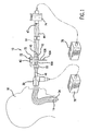
- the present invention provides for a respiratory apparatus 10 that may be removed from the ventilation circuit of a patient 18 and replaced without having to disconnect an artificial airway structure 30 from the ventilation circuit.
- the present invention may be used in conjunction with a variety of instruments that are placed into an artificial airway 34 of a patient 18.
- the present invention is shown as being used in conjunction with a suction catheter 12 and related apparatus.
- a ventilator 76 may be in communication with the artificial airway 34 through an artificial airway structure 30.
- the artificial airway structure 30 is sometimes known in the art as a manifold.
- the ventilator 76 may provide air to and remove air from the patient 18 through the artificial airway 34.
- the suction catheter 12 has a tubular portion 14 that may be extended through the artificial airway 34 into the lungs of the patient 18.
- a vacuum source 78 may be in communication with the ventilating circuit, and more specifically in communication with the suction catheter 12.
- a medical caregiver may actuate a suction valve 74 thereby applying a vacuum pressure to the tubular portion 14 of the suction catheter 12. Upon doing so, respiratory secretions in the patient 18 and in the artificial airway 34 may be removed.
- Respiratory secretions may sometimes remain on the tubular portion 14 of the suction catheter 12 or transfer onto other portions of the ventilator circuit. These respiratory secretions are undesirable in that they provide a breeding ground for pathogens and other harmful agents that may harm the patient 18. It is therefore the case that the suction catheter 12 and/or other components of the ventilation circuit may be cleaned in order to remove any residual respiratory secretions. However, in order to ensure a lower risk of contamination to the patient 18, it may be common practice to remove and replace the suction catheter 12 and/or other components in the ventilation circuit after some amount of set time has passed, for instance after 24 or 72 hours of use.
- the suction catheter 12 is shown with a flexible plastic sleeve 44.
- the sleeve 44 is present in order to contain and isolate respiratory secretions that accumulate on the tubular portion 14 of the suction catheter 12 as the tubular portion 14 is withdrawn from the ventilation circuit.
- the sleeve 44 may be provided on either end with sealing connections 45 and 47 that attach the sleeve 44 to the suction catheter 12.
- the respiratory apparatus 10 may be removably attached to the artificial airway structure 30.
- the artificial airway structure 30 may remain in place and allow for communication between the ventilator 76 and the artificial airway 34. As such, air may still be provided to the patient 18 during removal of the respiratory apparatus 10.
- a new respiratory apparatus 10 may be reattached to the same artificial airway structure 30.
- the suction catheter 12 may be releasably attachable to the respiratory apparatus 10, and may or may not be replaced with a new suction catheter 12 during replacement of the respiratory apparatus 10.
- the respiratory apparatus 10 in accordance with the present invention may be used in combination with a variety of artificial airway structures 30.
- the respiratory apparatus 10 may be used with a T-piece artificial airway structure 30.
- a port 90 is present and may be attached to the artificial airway 34 ( Fig. 1 ).
- the port 90 therefore allows for communication between the artificial airway structure 30 and the artificial airway 34.
- Air from the ventilator 76 ( Fig. 1 ) may be provided to and from the artificial airway structure 30 through a port 92.
- the port 92 may be attached to a pair of ventilation tubes via a connector (not shown).
- An additional port 94 on the artificial airway structure 30 may be provided opposite the port 92.
- the port 94 is typically covered with a cap 68 which is removed when "blow-by" is desired to wean the patient 18 ( Fig. 1 ) from forced ventilation.
- An additional port 46 may be configured to engage the respiratory apparatus 10 such that the respiratory apparatus 10 may be removably attached to the artificial airway structure 30.
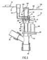
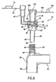
- the respiratory apparatus 10 is shown in greater detail in Fig. 2 .
- the respiratory apparatus 10 includes an instrument introduction section 22 to which an instrument such as the suction catheter 12 ( Fig. 1 ) may be attached in any suitable manner.
- the instrument introduction section 22 has a passageway 24 extending therethrough.
- the tubular portion 14 ( Fig. 1 ) of the suction catheter 12 may be advanced through the passageway 24, through an opening 98 in the distal end 28 of the instrument introduction section 22 and into the artificial airway structure 30, and eventually advanced into the artificial airway 34 ( Fig. 1 ).
- a wiper seal 36 may be provided in the instrument introduction section 22.
- the wiper seal 36 may be a resilient member having an aperture therethrough that allows for the tubular portion 14 to pass.
- the wiper seal 36 desirably tightly engages the tubular portion 14 as the tubular portion 14 is retracted into the proximal end 26 of the instrument introduction section 22. Respiratory secretions present on the surface of the tubular portion 14 may be removed by contact with the wiper seal 36.
- the instrument introduction section 22 may also be provided with a cleaning section 38.
- the cleaning section 38 may be defined by a cleaning section member 86. Additionally or alternatively, the cleaning section 38 may be defined on one end by a valve 32. Further, the cleaning section 38 may alternatively be defined by any portion of the instrument introduction section 22.
- the valve 32 shown in Fig. 2 is a single flap that is hingedly attached to an annular ring 31 housed within instrument introduction section 22. The hinge on the valve 32 may provide both a bias force and a pivoting location. Use of such a valve 32 is disclosed in U.S. Patent 6,227,200 B1 issued to Crump et al . The valve 32 may at least substantially block the passageway 24.
- the tubular portion 14 of the suction catheter 12 may have a distal end 16 with a distal opening 82.
- a lumen 20 extends through the tubular portion 14 and allows for respiratory secretions and other fluids to be transferred through the distal opening 82 and into the lumen 20 by the vacuum source 78 ( Fig. 1 ).
- the tubular portion 14 of the suction catheter 12 may be cleaned by positioning the distal end 16 of the suction catheter 12 either against the valve 32 and/or within the cleaning section 38. Upon so positioning, a vacuum can be effected upon the lumen 20 and lavage or other cleaning solution may be injected into the cleaning section 38. Application of the vacuum causes the valve 32 to be forced against the distal end 16 of the tubular portion 14. However, it is to be understood that injection of lavage or other cleaning solutions and/or application of a vacuum may be performed in other instances not associated with cleaning of the tubular portion 14.
- valve 32 need not contact the distal end 16 of the tubular portion 14 in order to effectively clean the tubular portion 14.
- the valve 32 may be urged against the cleaning section member 86 during cleaning of the tubular portion 14.
- the tubular portion 14 may also be provided with at least one side opening 84. This arrangement allows for turbulent flow to be established within the cleaning section 38 during suctioning causing the lavage solution to break up and remove any respiratory secretions present on the tubular portion 14. Respiratory secretions may be removed through the side opening 84 and/or the distal opening 82.
- the valve 32 may be provided with an aperture 42 therethrough. The presence of the aperture 42 may help to establish a more desirable turbulent fluid flow within the cleaning section 38. In one exemplary embodiment of the present invention, the aperture 42 may be about 0.03 inches in diameter.
- An irrigation port 40 may be attached to the instrument introduction section 22 in order to allow for the injection of the lavage solution.
- a container (not shown) holding the lavage solution may have an outlet inserted into the irrigation port 40. Lavage may then be dispensed from this container into the irrigation port 40 which may be in communication with the cleaning section 38.
- the irrigation port 40 may also be provided with an irrigation cap 70 that may be connected to the irrigation port 40 by way of a tether 72. The irrigation cap 70 may be placed onto the irrigation port 40 in order to close the irrigation port 40 when not in use.
- the cleaning section member 86 may be configured such that a small amount of space is present between the tubular portion 14 of the suction catheter 12 and the cleaning section member 86. In certain exemplary embodiments of the present invention, this space may be between about 0.005 and about 0.015 inches. This space provides two advantages. First, if lavage is needed to be provided to the patient 18, injection of lavage through the irrigation port 40 and then into the cleaning section 38 causes a stream of lavage solution to be directed out of the instrument introduction section 22 and into the patient 18. Second, as the tubular portion 14 is withdrawn the close proximity between the tubular portion 14 and the cleaning section member 86 may help to wipe any heavy layers of respiratory secretions from the outside of the tubular portion 14 of the suction catheter 12.
- valve 32 is advantageous in that the tubular portion 14 of the suction catheter 12 may be cleaned without causing a pressure loss to the ventilation circuit. This is because the valve 32 at least substantially isolates the portion of the respiratory apparatus 10 proximal the valve 32 from the remainder of the ventilation circuit.
- the valve 32 may be provided with one or more projections 88.
- Fig. 9 shows the respiratory apparatus 10 engaged with the artificial airway structure 30.
- the artificial airway structure 30 is a neonate manifold.
- the tubular portion 14 of the suction catheter 12 is shown as being advanced through the instrument introduction section 22, the artificial airway structure 30, and out of the port 90 eventually enabling entry of the artificial airway 34 ( Fig. 1 ) of the patient 18 ( Fig. 1 ).
- the valve 32 may be opened by insertion of the tubular portion 14 through the instrument introduction section 22.
- the projection 88 may be configured to minimize valve 32 contact with the surface of the tubular portion 14. This contact helps to reduce contamination of respiratory secretions from the tubular portion 14 onto the valve 32 and related components due to the minimized contact afforded by the projections 88. Additionally, in certain exemplary embodiments, this contact may help to ensure the structural integrity of the valve 32 and may minimize any unnecessary bending or stress on the valve 32.
- the valve 32 may be biased towards the closed position.
- the valve 32 may alternatively be attached, for example, directly onto a wall of the instrument introduction section 22.
- the valve 32 may be configured to be closed once the tubular portion 14 is positioned proximally from the valve 32, or alternatively the valve 32 may be configured to be closed upon the proximal positioning of the tubular portion 14 from the valve 32 and application of vacuum through the lumen 20 in order to draw the valve 32 into a closed position.
- valve 32 need not be a single flap in other exemplary embodiments of the present invention nor need it have the annular ring 31, nor need it have the aperture 42, or the projection 88. It is to be understood that the configuration of the valve 32 shown in the drawings is only a desired embodiment, and other configurations of the valve 32 are possible in accordance with the present invention.
- the valve 32 may be one, two, three, or more flaps that are biased towards a closed position and opened by insertion of the tubular portion 14 of the suction catheter 12 or any other suitable instrument through the instrument introduction section 22.
- the instrument introduction section 22 is provided with a proximal end 26 and a distal end 28.
- the proximal end 26 may be releasably attached to the suction catheter 12 through a variety of means commonly known in the art. For instance, these two components may be friction fit to one another, clamped to one another, or connected through a threaded engagement. Other suitable connections such as a snap fit, a latch, a boss and detent, etc. may be used.
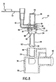
- the distal end 28 of the instrument introduction section 22 may be configured for being releasably attachable to a port 46 on the artificial airway structure 30. Engagement of the distal end 28 of the instrument introduction section 22 and the port 46 is shown in Fig. 3 .
- the distal end 28 may be friction fit onto the port 46. This provides for a secure attachment between the respiratory apparatus 10 and the artificial airway structure 30, but also allows for the disengagement of these two components once the desire to replace the respiratory apparatus 10 is present.
- the artificial airway structure 30 shown in Fig. 3 may be provided with an additional port 80 onto which the respiratory apparatus 10 may be attached in other exemplary embodiments.
- two respiratory apparatuses 10 may be employed such that their respective distal ends 28 are engageable with the port 46 and the port 80.
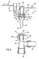
- the respiratory apparatus 10 is shown in Fig. 5 as being provided with a cap 100 placed on the proximal end 26 of the instrument introduction section 22.
- An opening 102 in the cap 100 may be provided through which the suction catheter 12 may be passed prior to being passed through an opening 96 in the proximal end 26 of the instrument introduction section 22.
- the opening 102 may be sized so that various instruments may be used in conjunction with the respiratory apparatus 10.
- the opening 102 may be closed by a plug 104 that is desirably connected to the cap 100 by way of a tether 106.
- Fig. 5 shows an exemplary embodiment where the plug 104 is inserted into the opening 102 ( Fig. 4 ), hence acting to close the opening 96 in the proximal end 26 of the instrument introduction section 22.
- Closing off the opening 96 may help to prevent contamination of the respiratory apparatus 10 by contaminants in the environment when instruments are not being used in conjunction with the respiratory apparatus 10. Additionally, during mechanical ventilation of the patient 18, it is advantageous to close the opening 96 so that positive end expiratory pressure can be maintained in the ventilation circuit. Although it is also possible to maintain the positive end expiratory pressure through the use of the valve 32 or a PEEP seal (not shown), the use of the plug 104 to close off the proximal end 26 provides for an alternative or supplemental way of maintaining the positive end expiratory pressure. As suggested above, the cap 100 need not be provided on the respiratory apparatus 10. For instance, Fig. 9 illustrates an exemplary embodiment that does not have such a cap 100 present.
- Figs. 14-16 show an alternative arrangement of the cap 100 and the plug 104 in accordance with an exemplary embodiment of the present invention.
- an attachment member 114 is present and may be attached to any component of the respiratory apparatus 10, for example the proximal end 26.
- the cap 100 is shown as being connected to the attachment member 114 by way of the tether 106, while the plug 104 is connected to the attachment member 114 by a separate plug tether 116.
- the cap 100 may be placed over a portion of the respiratory apparatus 10, for instance the opening 96. Further, when desired, the plug 104 may be placed within the opening 102 in the cap 100.
- Fig. 4 shows an alternate exemplary embodiment of the present invention where the cap 100 with the attachment member 114 may be attached to the port 46 of the artificial airway structure 30.
- the plug 104 may be inserted into the cap 100 in order to close off the port 46.
- Fig. 5 shows the cap 100 and plug 104 removed in order to allow attachment of the respiratory apparatus 10 to the artificial airway structure 30.
- the distal end 28 of the respiratory apparatus 10 may be inserted into the port 46 of the artificial airway structure 30 without removing the cap 100 from the port 46.
- the port 46 is in axial alignment with a swiveling port 62 that may be further attached to the artificial airway 34 ( Fig. 1 ).
- a rotating member 60 may be provided on the artificial airway structure 30 that allows for the rotation of the ports 46 and 80 such that port 80 may be axially aligned with the swiveling port 62, hence moving port 46 out of axial alignment with port 62.
- This type of artificial airway structure 30 is disclosed in U.S. Patent No. 5,735,271 to Lorenzen et al .
- the artificial airway structure 30 has another swiveling port 64 located thereon that is in communication with the ventilator 76.
- These two swiveling ports 62 and 64 are provided with a swiveling feature so that the tubing and/or structure connected to them more easily moves when various parts of the ventilation circuit are manipulated or moved. This helps to reduce stress imparted onto the patient 18 ( Fig. 1 ) brought about by movement of the ventilation circuit.
- the swiveling ports 62 and 64 may be constructed, for instance, as those disclosed in U.S. Patent No. 5,694,922 to Palmer .
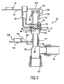
- FIG. 4 Another exemplary embodiment of the present invention is shown in Fig. 4 .
- the respiratory apparatus 10 may be substantially similar to the respiratory apparatus 10 described above with respect to the exemplary embodiment shown in Fig. 2 .
- the artificial airway structure 30 to which the respiratory apparatus 10 may be removably attached is in this instance an elbow manifold that has a pair of swiveling ports 62 and 64.
- Fig. 5 shows the respiratory apparatus 10 attached to the artificial airway structure 30 in much the same way as discussed above in respect to the exemplary embodiment shown in Fig. 3 , that being a friction fit arrangement between the port 46 and the distal end 28 of the instrument introduction section 22.
- the present invention is not limited to a particular amount of friction between the port 46 and the distal end 28 of the instrument introduction section 22.
- these two parts may be tightly fit with respect to one another such that a medical caregiver must provide a large amount of force in order to remove the distal end 28 of the instrument introduction section 22 from the port 46.
- these two parts may be fit together such that only a small amount of force is needed to remove the distal end 28 of the instrument introduction section 22 from the port 46.
- the present invention is to be understood as encompassing exemplary embodiments of the respiratory apparatus 10 that may be fit onto the artificial airway structure 30 with varying degrees of friction between these two components.
- the distal end 28 of the instrument introduction section 22 may in other exemplary embodiments be sized to fit around the port 46. Additionally, other friction fit arrangements between the port 46 and the distal end 28 are possible in accordance with the present invention as is commonly known in the art.
- the artificial airway structure 30 may be an elbow manifold that has ports 90 and 92 located thereon that do not include the swiveling feature. These two ports 90 and 92 form part of the ventilation circuit that provides air to and from the patient 18 ( Fig. 1 ) through the port 90 and provides air to and from the ventilator 76 ( Fig. 1 ) through the port 92.
- the respiratory apparatus 10 may be disengaged from the artificial airway structure 30 without the need to remove the artificial airway structure 30 from the remainder of the ventilation circuit. This helps to ensure that air is still provided to the patient 18 ( Fig. 1 ) during replacement of the respiratory apparatus 10.
- the artificial airway structure 30 may be provided with an artificial airway structure valve 66.
- the artificial airway structure valve 66 may prevent air loss during removal of the respiratory apparatus 10 by sealing off the port 46.
- the artificial airway structure valve 66 may take any design commonly known in the art.
- the artificial airway structure valve 66 may be a single flap that is substantially similar to the valve 32 of the instrument introduction section 22.
- the artificial airway structure valve 66 may be biased towards a closed position, and may be opened upon the insertion of the tubular portion 14 ( Fig. 1 ) through the port 46 and into the port 90.
- the artificial airway structure valve 66 may also be a plurality of flaps.
- the artificial airway structure valve 66 may be a mechanism that does not have flaps but yet still provides for a closed port 46 during disengagement of the respiratory apparatus 10 from the artificial airway structure 30.
- valve 32 and the artificial airway structure valve 66 may be of the other configurations in other exemplary embodiments of the present invention.
- configurations disclosed in commonly owned U.S. Patent 6,227,200 B1 issued to Crump et al . may be employed which may be a twisting membrane, a duckbill arrangement, or a dual membrane configuration having offset apertures.
- the artificial airway structure valve 66 may be configured such that it is closed during disengagement of the respiratory apparatus 10, but opened upon insertion of the distal end 28 of the instrument introduction section 22 into the port 46. Additionally, the artificial airway structure valve 66 may be configured to be opened by insertion of the tubular portion 14 ( Fig. 1 ) through the port 46 and into the artificial airway structure 30. In this instance, it may be the case that the artificial airway structure valve 66 is also in need of cleaning due to contact with respiratory secretions from the tubular portion 14. In this instance, the distal end 16 ( Fig. 1 ) of the tubular portion 14 may be located proximate to the artificial airway structure valve 66 and lavage solution may be injected into this location through the irrigation port 40. Vacuum may be applied to the lumen 20 of the tubular portion 14 and respiratory secretions present may then be removed via a process substantially the same as the cleaning procedure with respect to the valve 32.
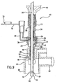
- Figs. 6 and 7 show a threaded engagement where the distal end 28 of the instrument introduction section 22 may have external threading 48 located thereon.
- the port 46 may have internal threading 50 located therein and is configured to mate with the external threading 48.
- Fig. 7 shows the threaded engagement between the respiratory apparatus 10 and the artificial airway structure 30. In order to effect this attachment, the medical caregiver needs to rotate the respiratory apparatus 10 and the artificial airway structure 30 with respect to one another.
- the artificial airway structure 30 is a neonate manifold having a plurality of ports. Three such ports are labeled 46, 90, and 92.
- the port 92 may provide access to and from the ventilator 76 ( Fig. 1 ), and the port 90 may provide access to and from the artificial airway 34 ( Fig. 1 ) of the patient.
- the port 46 may be configured to be releasably engageable with the distal end 28 of the respiratory suction catheter apparatus 10.
- the distal end 28 may be provided with a barb 52 that extends from the distal end 28.
- the barb 52 and the distal end 28 may be force fit into the port 46 and slid distally.
- the port 46 may be provided on one end with a receiving area 54 that is designed so as to receive the barb 52.
- the barb 52 is moved into the receiving area 54, the distal end 28 of the instrument introduction section 22 is retained in the port 46. This engagement is shown in Fig. 9 .
- the medical caregiver may provide a force tending to separate these two components. This force will be enough to compress the barb 52 and/or deform the distal end 28 such that they may be slid out of the port 46 and effect disengagement of the respiratory apparatus 10.
- the artificial airway structure 30 may be a T-piece manifold, having the port 46 located thereon in order to be releasably attached to the distal end 28 of the respiratory suction catheter apparatus 10.
- a clamping ring 56 may be provided and surrounds the exterior of the port 46.
- the clamping ring 56 may be a single piece of material, for instance metal or medical grade plastic, that exhibits at least a slight amount of flexibility.
- the clamping ring 56 has holes (not shown) on either end through which a screw 58 may be positioned.
- the distal end 28 of the instrument introduction section 22 may be inserted into the port 46 as shown in Fig.
- the screw 58 may be turned such that the two ends of the clamping ring 56 are urged towards one another. This in turn causes the port 46 to be compressed such that it is forced against the distal end 28 of the instrument introduction section 22 causing a secure attachment between the respiratory apparatus 10 and the artificial airway structure 30.
- a nut (not shown) may engage the screw 58 and may also be used to effect the constriction of the clamping ring 56 as is commonly known in the art.
- the screw 58 may be loosened in order to separate the two ends of the clamping ring 56 from one another. This loosens the connection between the distal end 28 and the port 46 and allows for the respiratory apparatus 10 to be removed from the artificial airway structure 30.
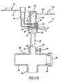
- FIG. 12 An additional exemplary embodiment of the present invention is shown in Fig. 12 .
- the respiratory apparatus 10 is configured substantially the same as the respiratory apparatus 10 of Fig. 2 .
- the artificial airway structure 30 onto which it is releasably attached is shown as a neonate Y-manifold.
- Fig. 13 shows the distal end 28 of the respiratory apparatus 10 being connected to the port 46 on the artificial airway structure 30 through a friction fit arrangement as previously described.
- Ports 90 and 92 of the artificial airway structure 30 allow for communication between the ventilator 76 and the artificial airway 34.
- a tapered adaptor 112 may be retained within the port 90 in order to allow for connection of the respirator apparatus 10 to tubing or other components of the respiratory circuit.
- the tapered adaptor 112 may or may not be permanently attached to the port 90.
- the artificial airway structure 30 itself may be tapered, hence eliminating the need for the tapered adaptor 112 in other exemplary embodiments of the present invention.
- the respiratory apparatus 10 may be sized such that it may be attached to a variety of artificial airway structures 30.
- the present invention includes various sizes of the respiratory apparatus 10 along with various sizes and configurations of the artificial airway structure 30.
- the examples of which described herein are only exemplary embodiments of the present invention and do not limit the present invention.
- various ways of releasably attaching the distal end 28 of the introduction section 22 to the artificial airway structure 30 are possible in accordance with the present invention, the mechanisms disclosed herein being only exemplary embodiments.
- Fig. 11 shows the respiratory apparatus 10 having a bronchoscope 108 inserted therethrough.
- the bronchoscope 108 may be inserted through the passageway 24, into the artificial airway structure 30, and into the artificial airway 34 of the patient 18 ( Fig. 1 ).
- the bronchoscope 108 may be cleaned in much the same way as describe above with respect to the suction catheter 12.
- the tip of the bronchoscope 108 may be positioned proximate to the valve 32, lavage solution may be injected into the cleaning section 38, and suction may be applied through the bronchoscope 108 so that respiratory sections are removed from the surface of the bronchoscope 108.
- other suitable instruments such as an endoscope, may be used in conjunction with the respiratory apparatus 10.
- the respiratory apparatus 10 therefore allows for different instruments to be placed therethrough and to be able to be cleaned by insertion of lavage solution and/or application of suction to the instrument.
- the respiratory apparatus 10 allows for different types of instruments to be inserted into the artificial airway 34 without having to disconnect the artificial airway structure 30 and cause the aforementioned interruption in ventilation air to the patient.
- valve 32 may act to maintain positive end expiratory pressure when in the closed position. It is to be understood that the present invention is not limited to a respiratory apparatus 10 that is used in conjunction with a suction catheter 12, but may be used with any suitable instrument that is to be inserted into the artificial airway 34. Therefore, different types of instruments may be interchanged with the respiratory apparatus 10.
Landscapes
- Health & Medical Sciences (AREA)
- Pulmonology (AREA)
- Emergency Medicine (AREA)
- Engineering & Computer Science (AREA)
- Anesthesiology (AREA)
- Biomedical Technology (AREA)
- Heart & Thoracic Surgery (AREA)
- Hematology (AREA)
- Life Sciences & Earth Sciences (AREA)
- Animal Behavior & Ethology (AREA)
- General Health & Medical Sciences (AREA)
- Public Health (AREA)
- Veterinary Medicine (AREA)
- Otolaryngology (AREA)
- External Artificial Organs (AREA)
- Prostheses (AREA)
- Electric Connection Of Electric Components To Printed Circuits (AREA)
- Percussion Or Vibration Massage (AREA)
- Respiratory Apparatuses And Protective Means (AREA)
Applications Claiming Priority (2)
| Application Number | Priority Date | Filing Date | Title |
|---|---|---|---|
| US10/430,814 US7556041B2 (en) | 2003-05-06 | 2003-05-06 | Respiratory apparatus having an introduction section configured for releasable attachment with a respiratory instrument |
| PCT/US2004/001412 WO2004101044A1 (en) | 2003-05-06 | 2004-01-20 | Respiratory apparatus having an introduction section configured for releasable attachment with a respiratory instrument |
Publications (2)
| Publication Number | Publication Date |
|---|---|
| EP1620148A1 EP1620148A1 (en) | 2006-02-01 |
| EP1620148B1 true EP1620148B1 (en) | 2008-09-03 |
Family
ID=33416320
Family Applications (1)
| Application Number | Title | Priority Date | Filing Date |
|---|---|---|---|
| EP04703666A Expired - Lifetime EP1620148B1 (en) | 2003-05-06 | 2004-01-20 | Respiratory apparatus having an introduction section configured for releasable attachment with a respiratory instrument |
Country Status (14)
| Country | Link |
|---|---|
| US (1) | US7556041B2 (enExample) |
| EP (1) | EP1620148B1 (enExample) |
| JP (1) | JP5068536B2 (enExample) |
| KR (1) | KR101092805B1 (enExample) |
| AT (1) | ATE406931T1 (enExample) |
| AU (1) | AU2004238186B2 (enExample) |
| BR (1) | BRPI0409662B1 (enExample) |
| CA (1) | CA2523460C (enExample) |
| DE (1) | DE602004016309D1 (enExample) |
| ES (1) | ES2309490T3 (enExample) |
| MX (1) | MXPA05011325A (enExample) |
| NO (1) | NO20054910L (enExample) |
| PT (1) | PT1620148E (enExample) |
| WO (1) | WO2004101044A1 (enExample) |
Cited By (9)
| Publication number | Priority date | Publication date | Assignee | Title |
|---|---|---|---|---|
| WO2011020985A1 (en) | 2009-08-20 | 2011-02-24 | Smiths Medical International Limited | Ventilation and suction systems and assemblies |
| CN106139341A (zh) * | 2015-03-26 | 2016-11-23 | 北京雅果科技有限公司 | 一种用于呼吸气路的三通管路及其检测方法 |
| WO2019077292A1 (en) | 2017-10-20 | 2019-04-25 | Smiths Medical International Limited | SUCTION CATHETER ASSEMBLIES |
| WO2020178540A1 (en) | 2019-03-02 | 2020-09-10 | Smiths Medical International Limited | Suction catheter assemblies and assemblies including a suction catheter assembly |
| WO2021079079A1 (en) | 2019-10-22 | 2021-04-29 | Smiths Medical International Limited | Connectors and assemblies |
| WO2021224585A1 (en) | 2020-05-04 | 2021-11-11 | Smiths Medical International Limited | Closed-system suction catheter assemblies and methods |
| WO2022023687A1 (en) | 2020-07-28 | 2022-02-03 | Smiths Medical International Limited | Closed-system suction catheter assemblies |
| WO2022238668A1 (en) | 2021-05-10 | 2022-11-17 | Smiths Medical International Limited | Suction catheter assemblies |
| EP4262939A4 (en) * | 2020-12-21 | 2024-11-13 | The Research Foundation for The State University of New York | Side port for addition of multiple drugs to a nebulizer |
Families Citing this family (45)
| Publication number | Priority date | Publication date | Assignee | Title |
|---|---|---|---|---|
| US7278420B2 (en) * | 2002-09-24 | 2007-10-09 | Thomas Jefferson University | Oropharyngeal airway |
| ITBO20050404A1 (it) * | 2005-06-15 | 2006-12-16 | Sherwood Serv Ag | Valvola di accesso broncotracheale per una apparecchiatura di broncoaspirazione |
| US8042545B2 (en) * | 2006-09-01 | 2011-10-25 | Al Medical Devices, Inc. | Endotracheal intubation and fluid delivery device |
| US20090095306A1 (en) * | 2007-10-09 | 2009-04-16 | Jeff Mandel | Oral device for intubation |
| US8302602B2 (en) | 2008-09-30 | 2012-11-06 | Nellcor Puritan Bennett Llc | Breathing assistance system with multiple pressure sensors |
| US20100147312A1 (en) * | 2008-12-12 | 2010-06-17 | John Brewer | Respiratory Access Port Assembly With Pin Lock and Method of Use |
| US8215306B2 (en) | 2008-12-12 | 2012-07-10 | Kimberly-Clark Worldwide, Inc. | Respiratory access port assembly with push button lock and method of use |
| US8307829B2 (en) * | 2008-12-23 | 2012-11-13 | Kimberly-Clark Worldwide, Inc. | Respiratory access assembly with rotating lock and method |
| US8205913B2 (en) * | 2008-12-31 | 2012-06-26 | Kimberly-Clark Worldwide, Inc. | Respiratory triple swivel manifold |
| US8444627B2 (en) * | 2008-12-31 | 2013-05-21 | Kimberly-Clark Worldwide, Inc. | Respiratory manifold with bridge |
| US8382908B2 (en) * | 2009-02-06 | 2013-02-26 | Endoclear, Llc | Methods for cleaning endotracheal tubes |
| US8468637B2 (en) | 2009-02-06 | 2013-06-25 | Endoclear Llc | Mechanically-actuated endotracheal tube cleaning device |
| GB0905219D0 (en) * | 2009-03-26 | 2009-05-13 | Smiths Medical Int Ltd | Suction catheter assemblies |
| US8256422B2 (en) * | 2009-05-15 | 2012-09-04 | Kimberly-Clark Worldwide, Inc | Respiratory access port assembly with passive lock and method of use |
| US9205212B2 (en) * | 2009-10-01 | 2015-12-08 | Covidien Ag | Transtracheal catheter apparatus |
| EP2902066B1 (en) | 2010-03-29 | 2021-03-10 | Endoclear LLC | Airway cleaning and visualization |
| JP2014527412A (ja) | 2011-03-29 | 2014-10-16 | エアウェイ メディックス スポルカ ゼット.オ.オ.Airway Medix Spolka Z.O.O. | バルーン型換気チューブクリーニング装置 |
| GB201119794D0 (en) | 2011-11-16 | 2011-12-28 | Airway Medix Spolka Z O O | Ballooned ventilation tube cleaning device |
| WO2013063520A1 (en) * | 2011-10-27 | 2013-05-02 | Endoclear, Llc | Endotracheal tube coupling adapters |
| US9364624B2 (en) | 2011-12-07 | 2016-06-14 | Covidien Lp | Methods and systems for adaptive base flow |
| US9078987B2 (en) | 2011-12-23 | 2015-07-14 | Avent, Inc. | Clutch brake assembly for a respiratory access port |
| US9498589B2 (en) | 2011-12-31 | 2016-11-22 | Covidien Lp | Methods and systems for adaptive base flow and leak compensation |
| US9022031B2 (en) | 2012-01-31 | 2015-05-05 | Covidien Lp | Using estimated carinal pressure for feedback control of carinal pressure during ventilation |
| US8844526B2 (en) | 2012-03-30 | 2014-09-30 | Covidien Lp | Methods and systems for triggering with unknown base flow |
| US10004863B2 (en) | 2012-12-04 | 2018-06-26 | Endoclear Llc | Closed suction cleaning devices, systems and methods |
| NL1039999C2 (en) * | 2013-01-14 | 2014-07-15 | Pacific Hospital Supply Co | Closed suction set insertable with bronchoscope. |
| US9492629B2 (en) | 2013-02-14 | 2016-11-15 | Covidien Lp | Methods and systems for ventilation with unknown exhalation flow and exhalation pressure |
| US9981096B2 (en) | 2013-03-13 | 2018-05-29 | Covidien Lp | Methods and systems for triggering with unknown inspiratory flow |
| EP2873433B1 (en) * | 2013-11-13 | 2016-05-18 | Vitaltec Corporation | Switchable adapter for a suction tube |
| KR101574772B1 (ko) * | 2014-02-06 | 2015-12-07 | 주식회사 인성메디칼 | 분리폐환기를 위한 이공튜브 접속장치 |
| US9427541B2 (en) | 2014-04-30 | 2016-08-30 | Vitaltec Corporation | Switchable adapter for a suction tube |
| US10016575B2 (en) | 2014-06-03 | 2018-07-10 | Endoclear Llc | Cleaning devices, systems and methods |
| US10500360B1 (en) | 2014-08-29 | 2019-12-10 | Teleflex Life Sciences Unlimited Company | Catheter for cleaning of tracheal ventilation tubes |
| US11285287B2 (en) | 2014-09-30 | 2022-03-29 | Frank H. Arlinghaus, Jr. | Tracheostomy or endotracheal tube adapter for speech |
| WO2016053574A1 (en) * | 2014-09-30 | 2016-04-07 | Arlinghaus Jr Frank H | A tracheostomy or endotracheal tube adapter for speech |
| US9925346B2 (en) | 2015-01-20 | 2018-03-27 | Covidien Lp | Systems and methods for ventilation with unknown exhalation flow |
| US11452831B2 (en) | 2016-01-06 | 2022-09-27 | Airway Medix S.A. | Closed suction system |
| GB2546082B (en) | 2016-01-06 | 2018-05-16 | Airway Medix S A | Closed suction system |
| US10946153B2 (en) | 2016-05-16 | 2021-03-16 | Teleflex Life Sciences Pte. Ltd. | Mechanical user control elements for fluid input module |
| US10864338B2 (en) * | 2017-05-19 | 2020-12-15 | Austere Medical Group, Llc | Rescue breathing apparatus |
| US10869979B2 (en) | 2017-08-09 | 2020-12-22 | Eric A. Cantor | Supraglottic airway device |
| DE102019111186A1 (de) | 2018-05-18 | 2019-11-21 | Spiration, Inc. D/B/A Olympus Respiratory America | Lungenbeatmungsvorrichtung |
| US11357939B2 (en) * | 2018-05-18 | 2022-06-14 | Gyrus Acmi, Inc. | Breathing lung device |
| DE102020000503B4 (de) | 2020-01-28 | 2023-02-02 | Drägerwerk AG & Co. KGaA | Gekrümmte Verbindungseinheit zum Verbinden eines Patienten mit einem Beatmungsgerät |
| US20210307593A1 (en) * | 2020-04-06 | 2021-10-07 | J & J Medical, LLC | Protective Sheath for Bronchoscope |
Family Cites Families (64)
| Publication number | Priority date | Publication date | Assignee | Title |
|---|---|---|---|---|
| US3991762A (en) * | 1974-09-30 | 1976-11-16 | Radford F Richard | Aspirating device for patient ventilation apparatus |
| US4152017A (en) * | 1977-08-08 | 1979-05-01 | Metatech Corporation | Swivel connector for endotracheal tube or the like |
| US4416273A (en) * | 1981-06-15 | 1983-11-22 | Grimes Jerry L | Connector valve assembly for endotracheal tubes |
| DE3222539C2 (de) * | 1982-06-16 | 1984-07-26 | Drägerwerk AG, 2400 Lübeck | Absaugadapter und Absauggerätesatz unter Verwendung dieses Adapters |
| US4573965A (en) * | 1984-02-13 | 1986-03-04 | Superior Plastic Products Corp. | Device for draining wounds |
| US4872579A (en) * | 1984-07-23 | 1989-10-10 | Ballard Medical Products | Aspirating/ventilating apparatus and method |
| US4836199A (en) * | 1984-07-23 | 1989-06-06 | Ballard Medical Products | Aspirating/ventilating apparatus and method |
| US4569344A (en) * | 1984-07-23 | 1986-02-11 | Ballard Medical Products | Aspirating/ventilating apparatus and method |
| US4696296A (en) * | 1984-07-23 | 1987-09-29 | Ballard Medical Products | Aspirating/ventilating apparatus |
| US4607635A (en) * | 1984-09-27 | 1986-08-26 | Heyden Eugene L | Apparatus for intubation |
| JPS62211074A (ja) * | 1986-03-07 | 1987-09-17 | ボ−ド・オブ・リ−ジエンツ、ザ・ユニバ−シテイ−・オブ・テキサス・システム | 先端バル−ン付き吸引カテ−テル |
| GB2199630A (en) | 1986-12-01 | 1988-07-13 | Portex Inc | Plug |
| US4846167A (en) * | 1987-03-30 | 1989-07-11 | Tibbals James R | Anti-disconnect device |
| US5582165A (en) * | 1988-02-28 | 1996-12-10 | Bryan; James F. | Pre-assembled sealed, sheathed catheters and related valve elements with quick disconnect means for endotracheal suctioning |
| US5220916A (en) * | 1990-06-14 | 1993-06-22 | Russo Ronald D | Tracheal suction catheter |
| US5083561B1 (en) * | 1990-06-14 | 1993-05-18 | D. Russo Ronald | Tracheal suction catheter |
| US5139018A (en) * | 1990-07-24 | 1992-08-18 | Superior Healthcare Group, Inc. | Patient ventilating apparatus with aspirating catheter |
| US5062420A (en) * | 1990-09-18 | 1991-11-05 | Walter Levine | Sealed swivel for respiratory apparatus |
| US5199427A (en) * | 1990-10-19 | 1993-04-06 | Ballard Medical Products | Multi-layered transtracheal caatheter |
| US5218957A (en) * | 1990-10-19 | 1993-06-15 | Ballard Medical Products | Multi-layered transtracheal catheter |
| US5230332A (en) * | 1990-10-22 | 1993-07-27 | Ballard Medical Products | Methods and apparatus for a micro-tracheal catheter hub assembly |
| US5255676A (en) * | 1991-11-08 | 1993-10-26 | Russo Ronald D | Safety sealed tracheal suction system |
| US5309902A (en) * | 1992-10-19 | 1994-05-10 | Sherwood Medical Company | Respiratory support system and suction catheter device therefor |
| US5645048A (en) * | 1992-05-06 | 1997-07-08 | The Kendall Company | Patient ventilating apparatus with modular components |
| US5355876A (en) * | 1992-05-06 | 1994-10-18 | Superior Healthcare Group, Inc. | Patient ventilating apparatus with modular components |
| GB2270845B (en) * | 1992-09-24 | 1996-07-10 | Smiths Ind Med Syst Inc | Suction catheter assemblies |
| US5445141A (en) * | 1992-10-19 | 1995-08-29 | Sherwood Medical Company | Respiratory support system |
| US5349950A (en) * | 1992-10-28 | 1994-09-27 | Smiths Industries Medical Systems, Inc. | Suction catheter assemblies |
| US5254098A (en) * | 1993-02-16 | 1993-10-19 | Smiths Industries Medical Systems, Inc. | Suction catheter assemblies |
| US5513628A (en) * | 1993-07-14 | 1996-05-07 | Sorenson Critical Care, Inc. | Apparatus and method for ventilating and aspirating |
| US5433195A (en) * | 1993-09-30 | 1995-07-18 | Sherwood Medical Company | Respiratory support system |
| US5676136A (en) * | 1993-12-07 | 1997-10-14 | Russo; Ronald D. | Protective suction control catheter with valve |
| US5490503A (en) * | 1994-04-29 | 1996-02-13 | Smiths Industries Medical Systems, Inc. | Suction catheter having multiple valves and collet assembly |
| US5735271A (en) * | 1994-05-18 | 1998-04-07 | Ballard Medical Products | Multiple access adaptors for monitoring, sampling, medicating, aspirating, and ventilating the respiratory tract of a patient |
| US5694922A (en) | 1994-05-18 | 1997-12-09 | Ballard Medical Products | Swivel tube connections with hermetic seals |
| US6494203B1 (en) * | 1994-08-19 | 2002-12-17 | Ballard Medical Products | Medical aspirating/ventilating closed system improvements and methods |
| US6012451A (en) * | 1994-08-19 | 2000-01-11 | Ballard Medical Products | Medical aspirating/ventilating closed system improvements and methods |
| EP0801577B1 (en) | 1994-09-19 | 2002-03-13 | Sorenson Medical, Inc. | Apparatus for ventilating and aspirating |
| US5582161A (en) * | 1994-12-08 | 1996-12-10 | Sherwood Medical Company | Sheathed catheter adapter and method of use |
| US5711294A (en) * | 1994-12-21 | 1998-01-27 | Sherwood Medical Company | Ventilator manifold having cleaning ports and method of use thereof |
| US5664594A (en) * | 1994-12-29 | 1997-09-09 | Sherwood Medical Company | Cleaning device for ventilator manifold and method of use thereof |
| WO1996026757A1 (en) | 1995-02-28 | 1996-09-06 | Ballard Medical Products | Access control respiratory devices and methods |
| US5598840A (en) * | 1995-03-17 | 1997-02-04 | Sorenson Critical Care, Inc. | Apparatus and method for ventilation and aspiration |
| US5775325A (en) * | 1995-05-11 | 1998-07-07 | Russo; Ronald D. | Two part closed tracheal suction system |
| US6082361A (en) * | 1997-09-12 | 2000-07-04 | Morejon; Orlando | Endotracheal tube cleaning apparatus |
| US6318368B1 (en) * | 1996-03-11 | 2001-11-20 | Orlando Morejon | Endotracheal tube cleaning apparatus |
| US5882348A (en) * | 1997-02-03 | 1999-03-16 | Sorenson Critical Care, Inc. | Valved manifold |
| US6026810A (en) * | 1997-07-30 | 2000-02-22 | Baird; David A. | One hand disconnectable device for artificial breathing apparatus to endotracheal tube connections |
| US6165168A (en) * | 1997-09-02 | 2000-12-26 | Russo; Ronald D. | Closed system adapter for catheters |
| US6227200B1 (en) * | 1998-09-21 | 2001-05-08 | Ballard Medical Products | Respiratory suction catheter apparatus |
| MXPA01002832A (es) | 1998-09-17 | 2002-04-08 | Ballard Med Prod | Aparato de cateter para succion respiratoria mejorado. |
| BR9804529A (pt) | 1998-10-23 | 2000-04-25 | Newmed Importadora Ltda | Dispositivo para realização de aspirador de secreções em pacientes entubados ou traquenostomizados e kit contendo um dispositivo para realização de aspiração de secreções em pacientes entubados ou tranqueostomizados. |
| US6615835B1 (en) * | 1999-09-20 | 2003-09-09 | Ballard Medical Products | Flexible multiple port adaptor |
| US6584970B1 (en) * | 1999-10-05 | 2003-07-01 | Ballard Medical Products | Retaining plug for endotracheal catheter and manifold assembly and method of use |
| MXPA02005898A (es) | 1999-12-13 | 2004-08-12 | Ballard Med Prod | Conjunto de multiple y de cateter endotraqueal con valvula mejorada. |
| US7152603B1 (en) | 1999-12-13 | 2006-12-26 | Kimberly-Clark Worldwide, Inc. | Endotracheal catheter and manifold assembly with improved valve |
| US6543451B1 (en) * | 1999-12-23 | 2003-04-08 | Kimberly-Clark Worldwide, Inc. | Endotracheal catheter and manifold assembly with improved seal and valve |
| EP1174518A1 (en) | 2000-07-20 | 2002-01-23 | Amsterdam Support Diagnostics B.V. | Collection of binding molecules |
| US6612304B1 (en) * | 2000-10-05 | 2003-09-02 | Kimberly-Clark Worldwide, Inc. | Respiratory care multiple access port assembly and adapter |
| US6609520B1 (en) | 2000-10-31 | 2003-08-26 | Kimberly-Clark Worldwide, Inc. | Closed suction catheter adaptor and assembly containing the same |
| IT1319876B1 (it) | 2000-11-24 | 2003-11-03 | D E A S S R L | Perfezionamenti ai sistemi di broncoaspirazione a circuito chiuso. |
| US6602219B2 (en) * | 2000-12-19 | 2003-08-05 | Kimberly-Clark Worldwide, Inc. | Turbulent air cleaning method and apparatus for catheter assemblies |
| US6588425B2 (en) * | 2000-12-21 | 2003-07-08 | Kimberly-Clark Worldwide, Inc. | Respiratory suction catheter apparatus with antimicrobial chamber |
| US6629530B2 (en) * | 2000-12-22 | 2003-10-07 | Kimberly-Clark Worldwide, Inc. | Single-element sealing valve for a respiratory support system |
-
2003
- 2003-05-06 US US10/430,814 patent/US7556041B2/en not_active Expired - Lifetime
-
2004
- 2004-01-20 WO PCT/US2004/001412 patent/WO2004101044A1/en not_active Ceased
- 2004-01-20 AT AT04703666T patent/ATE406931T1/de not_active IP Right Cessation
- 2004-01-20 ES ES04703666T patent/ES2309490T3/es not_active Expired - Lifetime
- 2004-01-20 JP JP2006532262A patent/JP5068536B2/ja not_active Expired - Lifetime
- 2004-01-20 MX MXPA05011325A patent/MXPA05011325A/es active IP Right Grant
- 2004-01-20 AU AU2004238186A patent/AU2004238186B2/en not_active Expired
- 2004-01-20 EP EP04703666A patent/EP1620148B1/en not_active Expired - Lifetime
- 2004-01-20 DE DE602004016309T patent/DE602004016309D1/de not_active Expired - Lifetime
- 2004-01-20 KR KR1020057019964A patent/KR101092805B1/ko not_active Expired - Fee Related
- 2004-01-20 PT PT04703666T patent/PT1620148E/pt unknown
- 2004-01-20 BR BRPI0409662A patent/BRPI0409662B1/pt not_active IP Right Cessation
- 2004-01-20 CA CA2523460A patent/CA2523460C/en not_active Expired - Lifetime
-
2005
- 2005-10-24 NO NO20054910A patent/NO20054910L/no unknown
Cited By (10)
| Publication number | Priority date | Publication date | Assignee | Title |
|---|---|---|---|---|
| WO2011020985A1 (en) | 2009-08-20 | 2011-02-24 | Smiths Medical International Limited | Ventilation and suction systems and assemblies |
| CN106139341A (zh) * | 2015-03-26 | 2016-11-23 | 北京雅果科技有限公司 | 一种用于呼吸气路的三通管路及其检测方法 |
| CN106139341B (zh) * | 2015-03-26 | 2018-09-18 | 北京雅果科技有限公司 | 一种用于呼吸气路的三通管路及其检测方法 |
| WO2019077292A1 (en) | 2017-10-20 | 2019-04-25 | Smiths Medical International Limited | SUCTION CATHETER ASSEMBLIES |
| WO2020178540A1 (en) | 2019-03-02 | 2020-09-10 | Smiths Medical International Limited | Suction catheter assemblies and assemblies including a suction catheter assembly |
| WO2021079079A1 (en) | 2019-10-22 | 2021-04-29 | Smiths Medical International Limited | Connectors and assemblies |
| WO2021224585A1 (en) | 2020-05-04 | 2021-11-11 | Smiths Medical International Limited | Closed-system suction catheter assemblies and methods |
| WO2022023687A1 (en) | 2020-07-28 | 2022-02-03 | Smiths Medical International Limited | Closed-system suction catheter assemblies |
| EP4262939A4 (en) * | 2020-12-21 | 2024-11-13 | The Research Foundation for The State University of New York | Side port for addition of multiple drugs to a nebulizer |
| WO2022238668A1 (en) | 2021-05-10 | 2022-11-17 | Smiths Medical International Limited | Suction catheter assemblies |
Also Published As
| Publication number | Publication date |
|---|---|
| JP5068536B2 (ja) | 2012-11-07 |
| KR20050119697A (ko) | 2005-12-21 |
| DE602004016309D1 (de) | 2008-10-16 |
| ES2309490T3 (es) | 2008-12-16 |
| ATE406931T1 (de) | 2008-09-15 |
| AU2004238186B2 (en) | 2009-06-18 |
| NO20054910L (no) | 2005-10-24 |
| CA2523460C (en) | 2012-05-08 |
| BRPI0409662A (pt) | 2006-04-18 |
| KR101092805B1 (ko) | 2011-12-12 |
| AU2004238186A1 (en) | 2004-11-25 |
| JP2006528531A (ja) | 2006-12-21 |
| PT1620148E (pt) | 2008-10-01 |
| CA2523460A1 (en) | 2004-11-25 |
| MXPA05011325A (es) | 2005-11-28 |
| EP1620148A1 (en) | 2006-02-01 |
| WO2004101044A1 (en) | 2004-11-25 |
| US7556041B2 (en) | 2009-07-07 |
| US20040221852A1 (en) | 2004-11-11 |
| BRPI0409662B1 (pt) | 2015-10-27 |
Similar Documents
| Publication | Publication Date | Title |
|---|---|---|
| EP1620148B1 (en) | Respiratory apparatus having an introduction section configured for releasable attachment with a respiratory instrument | |
| EP1620149B1 (en) | Respiratory suction catheter apparatus configured for releasable attachment with an artificial airway structure | |
| CA2523488C (en) | Respiratory apparatus having an instrument introduction section and manifold | |
| AU773472B2 (en) | Flexible multiple port adaptor | |
| EP2358421B1 (en) | Quick connect fitting for respiratory devices | |
| EP1239909A1 (en) | Endotracheal catheter and manifold assembly with seal and valve | |
| EP3151898A1 (en) | Cleaning devices, systems and methods | |
| MX2011006866A (es) | Ensamble para acceso respiratorio cn cierre giratorio y metodo. | |
| WO2013134088A2 (en) | Airway management apparatus | |
| US20040007236A1 (en) | Endotracheal surfactant distribution system |
Legal Events
| Date | Code | Title | Description |
|---|---|---|---|
| PUAI | Public reference made under article 153(3) epc to a published international application that has entered the european phase |
Free format text: ORIGINAL CODE: 0009012 |
|
| 17P | Request for examination filed |
Effective date: 20051024 |
|
| AK | Designated contracting states |
Kind code of ref document: A1 Designated state(s): AT BE BG CH CY CZ DE DK EE ES FI FR GB GR HU IE IT LI LU MC NL PT RO SE SI SK TR |
|
| DAX | Request for extension of the european patent (deleted) | ||
| 17Q | First examination report despatched |
Effective date: 20070131 |
|
| GRAP | Despatch of communication of intention to grant a patent |
Free format text: ORIGINAL CODE: EPIDOSNIGR1 |
|
| GRAS | Grant fee paid |
Free format text: ORIGINAL CODE: EPIDOSNIGR3 |
|
| GRAA | (expected) grant |
Free format text: ORIGINAL CODE: 0009210 |
|
| AK | Designated contracting states |
Kind code of ref document: B1 Designated state(s): AT BE BG CH CY CZ DE DK EE ES FI FR GB GR HU IE IT LI LU MC NL PT RO SE SI SK TR |
|
| REG | Reference to a national code |
Ref country code: GB Ref legal event code: FG4D |
|
| REG | Reference to a national code |
Ref country code: CH Ref legal event code: EP |
|
| REG | Reference to a national code |
Ref country code: IE Ref legal event code: FG4D Ref country code: PT Ref legal event code: SC4A Free format text: AVAILABILITY OF NATIONAL TRANSLATION Effective date: 20080919 |
|
| REF | Corresponds to: |
Ref document number: 602004016309 Country of ref document: DE Date of ref document: 20081016 Kind code of ref document: P |
|
| REG | Reference to a national code |
Ref country code: SE Ref legal event code: TRGR |
|
| REG | Reference to a national code |
Ref country code: ES Ref legal event code: FG2A Ref document number: 2309490 Country of ref document: ES Kind code of ref document: T3 |
|
| PG25 | Lapsed in a contracting state [announced via postgrant information from national office to epo] |
Ref country code: SI Free format text: LAPSE BECAUSE OF FAILURE TO SUBMIT A TRANSLATION OF THE DESCRIPTION OR TO PAY THE FEE WITHIN THE PRESCRIBED TIME-LIMIT Effective date: 20080903 Ref country code: AT Free format text: LAPSE BECAUSE OF FAILURE TO SUBMIT A TRANSLATION OF THE DESCRIPTION OR TO PAY THE FEE WITHIN THE PRESCRIBED TIME-LIMIT Effective date: 20080903 |
|
| PG25 | Lapsed in a contracting state [announced via postgrant information from national office to epo] |
Ref country code: BG Free format text: LAPSE BECAUSE OF FAILURE TO SUBMIT A TRANSLATION OF THE DESCRIPTION OR TO PAY THE FEE WITHIN THE PRESCRIBED TIME-LIMIT Effective date: 20081203 |
|
| PGFP | Annual fee paid to national office [announced via postgrant information from national office to epo] |
Ref country code: ES Payment date: 20090126 Year of fee payment: 6 |
|
| PG25 | Lapsed in a contracting state [announced via postgrant information from national office to epo] |
Ref country code: RO Free format text: LAPSE BECAUSE OF FAILURE TO SUBMIT A TRANSLATION OF THE DESCRIPTION OR TO PAY THE FEE WITHIN THE PRESCRIBED TIME-LIMIT Effective date: 20080903 Ref country code: SK Free format text: LAPSE BECAUSE OF FAILURE TO SUBMIT A TRANSLATION OF THE DESCRIPTION OR TO PAY THE FEE WITHIN THE PRESCRIBED TIME-LIMIT Effective date: 20080903 Ref country code: CZ Free format text: LAPSE BECAUSE OF FAILURE TO SUBMIT A TRANSLATION OF THE DESCRIPTION OR TO PAY THE FEE WITHIN THE PRESCRIBED TIME-LIMIT Effective date: 20080903 |
|
| PGFP | Annual fee paid to national office [announced via postgrant information from national office to epo] |
Ref country code: FI Payment date: 20090129 Year of fee payment: 6 Ref country code: PT Payment date: 20090105 Year of fee payment: 6 |
|
| PLBE | No opposition filed within time limit |
Free format text: ORIGINAL CODE: 0009261 |
|
| STAA | Information on the status of an ep patent application or granted ep patent |
Free format text: STATUS: NO OPPOSITION FILED WITHIN TIME LIMIT |
|
| PG25 | Lapsed in a contracting state [announced via postgrant information from national office to epo] |
Ref country code: EE Free format text: LAPSE BECAUSE OF FAILURE TO SUBMIT A TRANSLATION OF THE DESCRIPTION OR TO PAY THE FEE WITHIN THE PRESCRIBED TIME-LIMIT Effective date: 20080903 Ref country code: DK Free format text: LAPSE BECAUSE OF FAILURE TO SUBMIT A TRANSLATION OF THE DESCRIPTION OR TO PAY THE FEE WITHIN THE PRESCRIBED TIME-LIMIT Effective date: 20080903 |
|
| PGFP | Annual fee paid to national office [announced via postgrant information from national office to epo] |
Ref country code: BE Payment date: 20090219 Year of fee payment: 6 |
|
| 26N | No opposition filed |
Effective date: 20090604 |
|
| PG25 | Lapsed in a contracting state [announced via postgrant information from national office to epo] |
Ref country code: MC Free format text: LAPSE BECAUSE OF NON-PAYMENT OF DUE FEES Effective date: 20090131 |
|
| PGFP | Annual fee paid to national office [announced via postgrant information from national office to epo] |
Ref country code: SE Payment date: 20090128 Year of fee payment: 6 |
|
| REG | Reference to a national code |
Ref country code: CH Ref legal event code: PL |
|
| PG25 | Lapsed in a contracting state [announced via postgrant information from national office to epo] |
Ref country code: CH Free format text: LAPSE BECAUSE OF NON-PAYMENT OF DUE FEES Effective date: 20090131 Ref country code: LI Free format text: LAPSE BECAUSE OF NON-PAYMENT OF DUE FEES Effective date: 20090131 |
|
| PG25 | Lapsed in a contracting state [announced via postgrant information from national office to epo] |
Ref country code: IE Free format text: LAPSE BECAUSE OF NON-PAYMENT OF DUE FEES Effective date: 20090120 |
|
| REG | Reference to a national code |
Ref country code: PT Ref legal event code: MM4A Free format text: LAPSE DUE TO NON-PAYMENT OF FEES Effective date: 20100720 |
|
| BERE | Be: lapsed |
Owner name: KIMBERLY-CLARK WORLDWIDE, INC. Effective date: 20100131 |
|
| EUG | Se: european patent has lapsed | ||
| PG25 | Lapsed in a contracting state [announced via postgrant information from national office to epo] |
Ref country code: GR Free format text: LAPSE BECAUSE OF FAILURE TO SUBMIT A TRANSLATION OF THE DESCRIPTION OR TO PAY THE FEE WITHIN THE PRESCRIBED TIME-LIMIT Effective date: 20081204 |
|
| PG25 | Lapsed in a contracting state [announced via postgrant information from national office to epo] |
Ref country code: FI Free format text: LAPSE BECAUSE OF NON-PAYMENT OF DUE FEES Effective date: 20100120 |
|
| PG25 | Lapsed in a contracting state [announced via postgrant information from national office to epo] |
Ref country code: PT Free format text: LAPSE BECAUSE OF NON-PAYMENT OF DUE FEES Effective date: 20100720 |
|
| PG25 | Lapsed in a contracting state [announced via postgrant information from national office to epo] |
Ref country code: BE Free format text: LAPSE BECAUSE OF NON-PAYMENT OF DUE FEES Effective date: 20100131 |
|
| REG | Reference to a national code |
Ref country code: ES Ref legal event code: FD2A Effective date: 20110228 |
|
| PG25 | Lapsed in a contracting state [announced via postgrant information from national office to epo] |
Ref country code: LU Free format text: LAPSE BECAUSE OF NON-PAYMENT OF DUE FEES Effective date: 20090120 |
|
| PG25 | Lapsed in a contracting state [announced via postgrant information from national office to epo] |
Ref country code: HU Free format text: LAPSE BECAUSE OF FAILURE TO SUBMIT A TRANSLATION OF THE DESCRIPTION OR TO PAY THE FEE WITHIN THE PRESCRIBED TIME-LIMIT Effective date: 20090304 |
|
| PG25 | Lapsed in a contracting state [announced via postgrant information from national office to epo] |
Ref country code: ES Free format text: LAPSE BECAUSE OF NON-PAYMENT OF DUE FEES Effective date: 20110225 |
|
| PG25 | Lapsed in a contracting state [announced via postgrant information from national office to epo] |
Ref country code: TR Free format text: LAPSE BECAUSE OF FAILURE TO SUBMIT A TRANSLATION OF THE DESCRIPTION OR TO PAY THE FEE WITHIN THE PRESCRIBED TIME-LIMIT Effective date: 20080903 |
|
| PG25 | Lapsed in a contracting state [announced via postgrant information from national office to epo] |
Ref country code: CY Free format text: LAPSE BECAUSE OF FAILURE TO SUBMIT A TRANSLATION OF THE DESCRIPTION OR TO PAY THE FEE WITHIN THE PRESCRIBED TIME-LIMIT Effective date: 20080903 Ref country code: ES Free format text: LAPSE BECAUSE OF NON-PAYMENT OF DUE FEES Effective date: 20100121 |
|
| PG25 | Lapsed in a contracting state [announced via postgrant information from national office to epo] |
Ref country code: SE Free format text: LAPSE BECAUSE OF NON-PAYMENT OF DUE FEES Effective date: 20100121 |
|
| REG | Reference to a national code |
Ref country code: DE Ref legal event code: R082 Ref document number: 602004016309 Country of ref document: DE Representative=s name: ZIMMERMANN & PARTNER, DE |
|
| REG | Reference to a national code |
Ref country code: DE Ref legal event code: R081 Ref document number: 602004016309 Country of ref document: DE Owner name: AVENT, INC., ALPHARETTA, US Free format text: FORMER OWNER: KIMBERLY-CLARK WORLDWIDE, INC., NEENAH, WIS., US Effective date: 20150130 Ref country code: DE Ref legal event code: R082 Ref document number: 602004016309 Country of ref document: DE Representative=s name: ZIMMERMANN & PARTNER PATENTANWAELTE MBB, DE Effective date: 20150130 |
|
| REG | Reference to a national code |
Ref country code: GB Ref legal event code: 732E Free format text: REGISTERED BETWEEN 20150402 AND 20150408 |
|
| REG | Reference to a national code |
Ref country code: FR Ref legal event code: PLFP Year of fee payment: 13 |
|
| REG | Reference to a national code |
Ref country code: FR Ref legal event code: TP Owner name: AVENT, INC., US Effective date: 20160420 |
|
| REG | Reference to a national code |
Ref country code: NL Ref legal event code: PD Owner name: AVENT INC; US Free format text: DETAILS ASSIGNMENT: VERANDERING VAN EIGENAAR(S), OVERDRACHT; FORMER OWNER NAME: KIMBERLY-CLARK WORLDWIDE, INC. Effective date: 20160401 |
|
| REG | Reference to a national code |
Ref country code: FR Ref legal event code: PLFP Year of fee payment: 14 |
|
| REG | Reference to a national code |
Ref country code: FR Ref legal event code: PLFP Year of fee payment: 15 |
|
| PGFP | Annual fee paid to national office [announced via postgrant information from national office to epo] |
Ref country code: NL Payment date: 20171222 Year of fee payment: 15 |
|
| PGFP | Annual fee paid to national office [announced via postgrant information from national office to epo] |
Ref country code: IT Payment date: 20180102 Year of fee payment: 15 |
|
| REG | Reference to a national code |
Ref country code: NL Ref legal event code: MM Effective date: 20190201 |
|
| PG25 | Lapsed in a contracting state [announced via postgrant information from national office to epo] |
Ref country code: NL Free format text: LAPSE BECAUSE OF NON-PAYMENT OF DUE FEES Effective date: 20190201 |
|
| PG25 | Lapsed in a contracting state [announced via postgrant information from national office to epo] |
Ref country code: IT Free format text: LAPSE BECAUSE OF NON-PAYMENT OF DUE FEES Effective date: 20190120 |
|
| PGFP | Annual fee paid to national office [announced via postgrant information from national office to epo] |
Ref country code: GB Payment date: 20221201 Year of fee payment: 20 Ref country code: FR Payment date: 20221208 Year of fee payment: 20 |
|
| PGFP | Annual fee paid to national office [announced via postgrant information from national office to epo] |
Ref country code: DE Payment date: 20221123 Year of fee payment: 20 |
|
| P01 | Opt-out of the competence of the unified patent court (upc) registered |
Effective date: 20230518 |
|
| REG | Reference to a national code |
Ref country code: DE Ref legal event code: R071 Ref document number: 602004016309 Country of ref document: DE |
|
| REG | Reference to a national code |
Ref country code: GB Ref legal event code: PE20 Expiry date: 20240119 |
|
| PG25 | Lapsed in a contracting state [announced via postgrant information from national office to epo] |
Ref country code: GB Free format text: LAPSE BECAUSE OF EXPIRATION OF PROTECTION Effective date: 20240119 |