EP1619935A2 - Emergency lighting power supply unit with digital addressable control interface - Google Patents
Emergency lighting power supply unit with digital addressable control interface Download PDFInfo
- Publication number
- EP1619935A2 EP1619935A2 EP05014709A EP05014709A EP1619935A2 EP 1619935 A2 EP1619935 A2 EP 1619935A2 EP 05014709 A EP05014709 A EP 05014709A EP 05014709 A EP05014709 A EP 05014709A EP 1619935 A2 EP1619935 A2 EP 1619935A2
- Authority
- EP
- European Patent Office
- Prior art keywords
- emergency light
- normal operation
- light element
- electronic ballast
- ecg
- Prior art date
- Legal status (The legal status is an assumption and is not a legal conclusion. Google has not performed a legal analysis and makes no representation as to the accuracy of the status listed.)
- Granted
Links
- 238000011990 functional testing Methods 0.000 claims description 6
- 238000002565 electrocardiography Methods 0.000 description 45
- 238000004891 communication Methods 0.000 description 2
- 239000004020 conductor Substances 0.000 description 2
- 230000007935 neutral effect Effects 0.000 description 2
- 230000002349 favourable effect Effects 0.000 description 1
- 238000004519 manufacturing process Methods 0.000 description 1
- 238000000034 method Methods 0.000 description 1
- 238000012544 monitoring process Methods 0.000 description 1
- 230000005405 multipole Effects 0.000 description 1
- 230000001960 triggered effect Effects 0.000 description 1
Images


Classifications
-
- H—ELECTRICITY
- H02—GENERATION; CONVERSION OR DISTRIBUTION OF ELECTRIC POWER
- H02J—CIRCUIT ARRANGEMENTS OR SYSTEMS FOR SUPPLYING OR DISTRIBUTING ELECTRIC POWER; SYSTEMS FOR STORING ELECTRIC ENERGY
- H02J9/00—Circuit arrangements for emergency or stand-by power supply, e.g. for emergency lighting
- H02J9/02—Circuit arrangements for emergency or stand-by power supply, e.g. for emergency lighting in which an auxiliary distribution system and its associated lamps are brought into service
-
- H—ELECTRICITY
- H05—ELECTRIC TECHNIQUES NOT OTHERWISE PROVIDED FOR
- H05B—ELECTRIC HEATING; ELECTRIC LIGHT SOURCES NOT OTHERWISE PROVIDED FOR; CIRCUIT ARRANGEMENTS FOR ELECTRIC LIGHT SOURCES, IN GENERAL
- H05B47/00—Circuit arrangements for operating light sources in general, i.e. where the type of light source is not relevant
- H05B47/10—Controlling the light source
- H05B47/175—Controlling the light source by remote control
- H05B47/18—Controlling the light source by remote control via data-bus transmission
Definitions
- the present invention relates to an emergency light element having a digitally addressable control interface.
- emergency lighting elements are provided in addition to electronic ballasts for normal operation, such as ballasts, the low-pressure discharge lamps can operate on household mains voltage.
- These emergency lighting elements are intended for safety reasons in the event of failure of the mains supply and therefore have a battery or a battery connection and a device for detecting the emergency light case, d. H. of the power supply failure, on.
- the battery is integrated.
- a ballast for operating a lamp is provided on the battery, which is put into operation in case of emergency. This then operates a specially provided for this purpose or even used in normal operation case lamp and thus provides emergency lighting.
- Such emergency lighting elements are known per se, in particular as complete lights with the lamp to be operated in the emergency light case.
- the present invention is therefore based on the technical problem of providing an advantageous emergency light element which is well suited for use in a digitally controlled lighting system.
- the invention is directed to an emergency light element with a battery connection, a device for detecting a power supply failure and designed for the battery operation of a lamp electronic ballast, characterized in that the emergency light element has a digitally addressable control interface and a control output for an electronic ballast for normal operation and to is designed to control the electronic ballast for normal operation in normal operation via the digitally addressable control interface.
- the invention therefore provides to equip an emergency light element on the one hand with a digitally addressable control interface, but also to provide a control output for an electronic ballast for normal operation (hereinafter for the sake of brevity normal ECG). So it is a control of a normal operation ECG on the provided emergency light element according to the invention. This can be dispensed with a separate digitally addressable control interface of the normal operation ECG, so that a certain technical effort, but especially a digital address, can be saved.
- the emergency light element has a connection for a lamp to be operated in an emergency light case, which can be connected to the electronic ballast designed for battery operation within the emergency light element. Furthermore, however, the emergency light element here also has a connection for the normal operation ECG, via which this lamp can operate in normal operation. It is therefore switched in the emergency light case of lamp operation by the normal operation ECG to the "emergency ECG" within the emergency light element.
- the lamp is integrated, so it is a total of an emergency light.
- the normal operation ECG is integrated. This is either a combined normal / emergency light or, if no lamp is integrated, a combined normal / emergency ECG.
- the invention also relates to embodiments in which the lamp and / or the normal operation ECG are provided externally and can be connected to the emergency light element only.
- control output here includes not only exclusive control signal outputs, but also outputs that have, inter alia, control functions, ie control operations of the emergency light element output.
- control output can be a supply output, such as a phase output, which can be switched off in a controlled manner within the emergency light element even if the mains supply continues to be present. This should apply even in the event that the emergency light element, as preferred, has an input for an externally connected mains supply (in particular phase).
- the shutdown of this supply output for the normal operation ECG is in response to control signals received via the digitally addressable interface.
- the emergency light element may be used within (at least in part) digitally controlled lighting systems along with a conventional normal operation ECG that itself is not digitally addressable.
- This normal operation ECG can then be switched on and off, for example, via the already mentioned externally switched phase, which however is connected via the emergency light element.
- the emergency light element can switch off this supply of the normal operation ECG in response to digital control signals.
- the digital control running functional tests of the emergency light functions in which then the or the normal operation ECG must be turned off, although the actual mains supply is still available.
- the control output is a separate digital output.
- the normal operation electronic ballast which in this case also has a digitally addressable interface of an identical or compatible type.
- the emergency light element generates different kind of digital control signals and outputs to the normal operation ECG.
- these are preferably internally of relevance to the Emergency light element self-tested.
- the emergency light element can interrogate certain operating and configuration parameters of the normal operation ECG periodically and store it in an internal memory in order to be able to answer queries about the state of the normal operation electronic ballast without or with a slight time delay.
- the emergency light element according to the invention can also be combined with a plurality of normal operation ECGs, whether they are integrated or external. These can also be controlled via one and the same control output, in the case of the separate digital control output thus in the sense of a bus line and in the case of the control output switching control output in the sense of a parallel connection.
- the emergency light element preferably has further connections for a functional test device which is connected locally in order to test the individual emergency light element. Where this is required, a local test and display option can be realized.
- the invention is directed to electronic ballasts in the most general sense, so on any form of operating devices for lamps.
- ECGs for low-pressure discharge lamps for example in tubular form or as so-called energy-saving lamps.
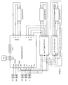
- FIG. 1 shows an emergency light element according to the invention in a particularly simple application situation.
- the emergency light element is in this embodiment part of an emergency light and operates the right-drawn tubular low-pressure discharge lamp type FH 14W. It also contains a not-shown in Figure 1 emergency ECG and a top left battery connected to the same supply.
- the emergency light bulb is operated via lamp terminals with the designation lamps 1 to 4 and used in the application shown here only as an emergency light bulb.
- DA In the left upper area are marked with DA designated terminals, which are differentiated by DA system and DA ECG.
- the DA system is connected to external lines, namely control signal lines of a digital central control system. This is the control of a larger lighting system, which controls the connected devices according to the so-called DALI standard (digital addressable lighting interface) via respective digitally addressable interfaces.
- DALI digital addressable lighting interface
- the emergency light element contains supply lines, namely a phase L, a neutral conductor N and a ground PE, which are connected to identical connections.
- supply lines namely a phase L, a neutral conductor N and a ground PE, which are connected to identical connections.
- the importance of the unused connections L 'and L Q will be discussed in more detail.
- connection designated RJ11 is provided at the top in the center, which serves to connect an external test device for local functional tests of the emergency light element.
- the tester is shown with a switch symbol and a light-emitting diode symbol.
- the emergency light element is additionally connected via the terminals ECG 1-4 with a dimmable normal operation ECG for two 54W lamps, here the type QT FQ 2x54 DIM.
- This normal operation electronic ballast can operate the already mentioned emergency light bulb in normal operation via the connections ECG 1-4. Furthermore, the normal operation ECG can be a right next to him drawn additional lamp operate the same type, which is not operated in an emergency light case. So it is a two-lamp with emergency light function.
- This conventional ECG is supplied on the one hand directly via the neutral conductor N from the mains supply and on the other hand via the phase output L Q of the emergency light element.
- the phase output L Q is switchably connected to the phase input L 'of the emergency light element, which is supplied via the line L SW .
- This is an externally switched phase, which can thus be switched off in contrast to the continuous supply phase L in order to control the mentioned normal operation ECG.
- the internal connection between the terminals L 'and L Q in the emergency light element is switchable, so that a digital control signal (for example via the terminals DA system) can open the connection between L' and L Q.
- the normal operation ECG can therefore be switched off, even though there is no emergency light case, ie the continuous phase L is active, and moreover not even the externally switched phase L SW was switched off externally.
- This can be simulated via the digital control in the emergency light element emergency lighting case without the normal operation ECG would have to implement the digital control signals themselves.
- a further analogue connection of the normal operation electronic ballast is also shown, which may be, for example, a dimming control terminal.
- This example thus shows in particular a two-lamp emergency light in a lighting system with a mixed digital / analog control.
- the control output for controlling the normal operation ECG is the switched phase output L Q which can be switched off by the emergency light element independently of the phase input L or L 'when corresponding control signals are received via the digitally addressable DA system interface.
- FIG. 3 shows the emergency light element from the previous figures together with another additional normal operation ECG. So it may be a total of a three-lamp with emergency light function or it could be the third ECG connected as an external ECG to a two-lamp with emergency light function.
- both normal-mode ECGs specifically of the type QT DALI FQ 2x54 or QT DALI FQ 1x54
- the luminaire including the potentially external third electronic ballast
- All DALI commands are passed from the emergency light element to the DALI ECG.
- the commands received by the digital control unit of the system must be interpreted by the emergency light element and partially executed by itself.
- the emergency light element In order to be able to correctly answer status queries of the control unit on the one hand and queries of the DALI ECG on the other hand, the emergency light element must also store the received control commands and periodically determine and save the status of the downstream ECGs.
- the emergency light-specific DALI commands must be processed and the battery condition and the mains voltage constantly monitored.
- the emergency light element thus has the function of a DALI-controlled emergency light element with integrated control unit for further DALI ECGs.
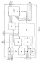
- FIG. 4 shows the internal structure of the emergency light element from FIGS. 1-3.
- the designation of the connections corresponds to the mentioned figures.
- the individual function blocks essentially have the following function:
- the digitally addressable interface is designated DS1.
- Another digital interface DS2 is used for communication with the DALI ECGs.
- the block PS generates the internal supply voltages from the already mentioned mains supply.
- the block BM contains the charging and monitoring electronics for the battery management and is therefore connected on the one hand to the block PS and the other to the battery terminal BAT.
- the abbreviation NM stands for network monitor. This monitors the applied mains voltage and thus detects the presence of an emergency light situation. The network monitor also detects the state of the switched network input L '. The monitored functions are forwarded to the digital sequencer AS described below.
- the block MS switches the supply voltage of the connected in Figure 2 to the terminal L Q EVG, thus forms the switch between the terminals L 'and L Q and is controlled by the sequence controller AS.
- WR stands for an inverter, namely an ECG optimized for battery operation for the operation of the connected low-pressure discharge lamp (eg FQ 54W) in the event of an emergency, possibly with reduced power. Therefore, the inverter is connected to the battery terminal BAT and, on the other hand, is controlled by the sequence controller AS.
- the inverter is connected to the battery terminal BAT and, on the other hand, is controlled by the sequence controller AS.
- LS designates a multi-pole changeover switch which decouples the lamp connected on the top right in the emergency light mode from the normal operating ECG connected to the connections EVG 1-4 and connects it to the inverter WR.
- AS designates the central digital sequence control, which contains, among other things, the software elements necessary for digital DALI communication, necessary clocks, and a decision logic for switching between normal and emergency lighting operation.
- the emergency light element of Figure 4 can be used in the manner illustrated in Figures 1-3 for controlling normal operation electronic ballast and occupies only one digital address in each case. It allows in all cases triggered and monitored by centralized digital control, including the creation of result logs, as required in some cases. Furthermore, the tests can also be performed "manually" on the individual luminaires via the additional RJ11 connection, and their results can be displayed locally.
- the normal operation ECGs can be external or integrated. The same applies to the low-pressure discharge lamps.
Abstract
Description
Die vorliegende Erfindung bezieht sich auf ein Notlichtelement mit einer digital adressierbaren Steuerschnittstelle.The present invention relates to an emergency light element having a digitally addressable control interface.
Bei vielen Beleuchtungsaufgaben werden zusätzlich zu elektronischen Vorschaltgeräten für den Normalbetrieb, etwa Vorschaltgeräten, die Niederdruckentladungslampen an Haushaltsnetzspannung betreiben können, so genannte Notlichtelemente vorgesehen. Diese Notlichtelemente sind aus Sicherheitsgründen für den Fall eines Ausfalls der Netzversorgung gedacht und weisen daher eine Batterie oder einen Batterieanschluss und eine Einrichtung zum Erkennen des Notlichtfalls, d. h. des Netzversorgungsausfalls, auf. Im Regelfall ist die Batterie integriert. Unabhängig davon ist jedenfalls ein Vorschaltgerät zum Betrieb einer Lampe an der Batterie vorgesehen, das im Notlichtfall in Betrieb genommen wird. Dieses betreibt dann eine eigens für diesen Zweck vorgesehene oder auch bereits im Normalbetriebsfall verwendete Lampe und sorgt damit für eine Notbeleuchtung.In many lighting tasks so-called emergency lighting elements are provided in addition to electronic ballasts for normal operation, such as ballasts, the low-pressure discharge lamps can operate on household mains voltage. These emergency lighting elements are intended for safety reasons in the event of failure of the mains supply and therefore have a battery or a battery connection and a device for detecting the emergency light case, d. H. of the power supply failure, on. As a rule, the battery is integrated. Regardless of any case, a ballast for operating a lamp is provided on the battery, which is put into operation in case of emergency. This then operates a specially provided for this purpose or even used in normal operation case lamp and thus provides emergency lighting.
Solche Notlichtelemente sind an sich bekannt, insbesondere auch als komplette Leuchten mit der im Notlichtfall zu betreibenden Lampe.Such emergency lighting elements are known per se, in particular as complete lights with the lamp to be operated in the emergency light case.
Ferner ist bekannt, dass solche Notlichtelemente innerhalb größerer Beleuchtungsanlagen eingesetzt werden, bei denen sich die Notwendigkeit einer Beleuchtung auch im Falle eines Versorgungsausfalls häufig in besonderem Maße stellt, etwa um eine Evakuierung sicherzustellen oder eine Panik oder Unfälle zu vermeiden.Furthermore, it is known that such emergency lighting elements are used within larger lighting systems, in which the need for lighting in the case of a power failure is often in particular, for example to ensure evacuation or to avoid panic or accidents.
Schließlich sind in jüngster Zeit Beleuchtungsanlagen bekannt geworden, die über digitale Steuersignale gesteuert werden, bei denen die verwendeten Vorschaltgeräte also digital adressierbare Schnittstellen zum Empfangen von Steuersignalen aufweisen.Finally, lighting systems have become known recently, which are controlled by digital control signals, in which the ballasts used so have digitally addressable interfaces for receiving control signals.
Der vorliegenden Erfindung liegt damit das technische Problem zugrunde, ein vorteilhaftes Notlichtelement anzugeben, das sich gut für die Verwendung in einer digital gesteuerten Beleuchtungsanlage eignet.The present invention is therefore based on the technical problem of providing an advantageous emergency light element which is well suited for use in a digitally controlled lighting system.
Die Erfindung richtet sich auf ein Notlichtelement mit einem Batterieanschluss, einer Einrichtung zum Erkennen eines Netzversorgungsausfalls und einem für den Batteriebetrieb einer Lampe ausgelegten elektronischen Vorschaltgerät, dadurch gekennzeichnet, dass das Notlichtelement eine digital adressierbare Steuerschnittstelle und einen Steuerausgang für ein elektronisches Vorschaltgerät für Normalbetrieb aufweist und dazu ausgelegt ist, das elektronische Vorschaltgerät für Normalbetrieb im Normalbetrieb über die digital adressierbare Steuerschnittstelle steuern zu lassen.The invention is directed to an emergency light element with a battery connection, a device for detecting a power supply failure and designed for the battery operation of a lamp electronic ballast, characterized in that the emergency light element has a digitally addressable control interface and a control output for an electronic ballast for normal operation and to is designed to control the electronic ballast for normal operation in normal operation via the digitally addressable control interface.
Die Erfindung sieht also vor, ein Notlichtelement einerseits mit einer digital adressierbaren Steuerschnittstelle auszustatten, darüber hinaus aber auch noch einen Steuerausgang für ein elektronisches Vorschaltgerät für den Normalbetrieb (im Folgenden der Kürze halber Normalbetrieb-EVG) vorzusehen. Es ist also eine Ansteuerung eines Normalbetrieb-EVG über das erfindungsgemäße Notlichtelement vorgesehen. Damit kann auf eine separate digital adressierbare Steuerschnittstelle des Normalbetrieb-EVG verzichtet werden, so dass ein gewisser technischer Aufwand, vor allem jedoch eine digitale Adresse, eingespart werden.The invention therefore provides to equip an emergency light element on the one hand with a digitally addressable control interface, but also to provide a control output for an electronic ballast for normal operation (hereinafter for the sake of brevity normal ECG). So it is a control of a normal operation ECG on the provided emergency light element according to the invention. This can be dispensed with a separate digitally addressable control interface of the normal operation ECG, so that a certain technical effort, but especially a digital address, can be saved.
Ferner lassen sich, wie das Ausführungsbeispiel weiter unten verdeutlicht, flexible Lösungen finden, die insbesondere auch günstige Möglichkeiten für Funktionstests bieten.Furthermore, as the exemplary embodiment illustrated below, flexible solutions can be found which, in particular, also offer favorable possibilities for functional tests.
Bei einer vorteilhaften Ausführungsform weist das Notlichtelement einerseits einen Anschluss für eine im Notlichtfall zu betreibende Lampe auf, der mit dem für den Batteriebetrieb ausgelegten EVG innerhalb des Notlichtelements verbindbar ist. Ferner weist das Notlichtelement hierbei jedoch auch einen Anschluss für das Normalbetrieb-EVG auf, über den dieses diese Lampe im Normalbetrieb betreiben kann. Es wird also im Notlichtfall vom Lampenbetrieb durch das Normalbetrieb-EVG auf das "Notlicht-EVG" innerhalb des Notlichtelements umgeschaltet.In an advantageous embodiment, the emergency light element, on the one hand, has a connection for a lamp to be operated in an emergency light case, which can be connected to the electronic ballast designed for battery operation within the emergency light element. Furthermore, however, the emergency light element here also has a connection for the normal operation ECG, via which this lamp can operate in normal operation. It is therefore switched in the emergency light case of lamp operation by the normal operation ECG to the "emergency ECG" within the emergency light element.
Vorteilhafterweise ist die Lampe integriert, handelt es sich also insgesamt um eine Notlichtleuchte. Ebenfalls vorteilhafterweise ist das Normalbetrieb-EVG integriert. Damit handelt es sich entweder um eine kombinierte Normalbetrieb-/Notlichtleuchte oder, wenn keine Lampe integriert ist, um ein kombiniertes Normalbetrieb-/Notlicht-EVG. Natürlich bezieht sich die Erfindung aber auch auf Ausführungsformen, bei denen die Lampe und/oder das Normalbetrieb-EVG extern vorgesehen sind und an das Notlichtelement lediglich angeschlossen werden können.Advantageously, the lamp is integrated, so it is a total of an emergency light. Also advantageously, the normal operation ECG is integrated. This is either a combined normal / emergency light or, if no lamp is integrated, a combined normal / emergency ECG. Of course, the invention also relates to embodiments in which the lamp and / or the normal operation ECG are provided externally and can be connected to the emergency light element only.
Eine spezifische Ausführungsform der Erfindung sieht einen steuerbaren Versorgungsausgang für das Normalbetrieb-EVG vor. Der Begriff Steuerausgang beinhaltet hier also nicht nur ausschließliche Steuersignalausgänge, sondern auch Ausgänge, die unter anderem Steuerfunktionen haben, d. h. Steuervorgänge des Notlichtelements ausgeben. Es kann sich insbesondere um einen Versorgungsausgang, etwa einen Phasenausgang handeln, der auch bei weiterhin vorhandener Netzversorgung in gesteuerter Weise innerhalb des Notlichtelements abschaltbar ist. Dies soll selbst für den Fall gelten, dass das Notlichtelement, wie bevorzugt, über einen Eingang für eine extern geschaltete Netzversorgung (insbesondere Phase) verfügt. Das Abschalten dieses Versorgungsausgangs für das Normalbetrieb-EVG erfolgt ansprechend auf Steuersignale, die über die digital adressierbare Schnittstelle eingehen.A specific embodiment of the invention provides a controllable supply output for the normal operation ECG. The term control output here includes not only exclusive control signal outputs, but also outputs that have, inter alia, control functions, ie control operations of the emergency light element output. In particular, it can be a supply output, such as a phase output, which can be switched off in a controlled manner within the emergency light element even if the mains supply continues to be present. This should apply even in the event that the emergency light element, as preferred, has an input for an externally connected mains supply (in particular phase). The shutdown of this supply output for the normal operation ECG is in response to control signals received via the digitally addressable interface.
Bei dieser Ausführungsform kann das Notlichtelement innerhalb (zumindest teilweise) digital gesteuerter Beleuchtungsanlagen zusammen mit einem konventionellen Normalbetrieb-EVG verwendet werden, das selbst nicht digital adressierbar ist. Dieses Normalbetrieb-EVG kann dann beispielsweise über die bereits erwähnte extern geschaltete Phase ein- und ausgeschaltet werden, die jedoch über das Notlichtelement angeschlossen wird. Dabei kann das Notlichtelement ansprechend auf digitale Steuersignale diese Versorgung des Normalbetrieb-EVG abschalten. Damit können beispielsweise über die digitale Steuerung ablaufende Funktionstests der Notlichtfunktionen erfolgen, bei denen dann das oder die Normalbetrieb-EVG abgeschaltet werden müssen, obwohl die eigentliche Netzversorgung weiterhin vorhanden ist.In this embodiment, the emergency light element may be used within (at least in part) digitally controlled lighting systems along with a conventional normal operation ECG that itself is not digitally addressable. This normal operation ECG can then be switched on and off, for example, via the already mentioned externally switched phase, which however is connected via the emergency light element. In this case, the emergency light element can switch off this supply of the normal operation ECG in response to digital control signals. Thus, for example, via the digital control running functional tests of the emergency light functions, in which then the or the normal operation ECG must be turned off, although the actual mains supply is still available.
Bei einer anderen vorteilhaften Ausgestaltung, die aber durchaus zusätzlich zu der bereits beschriebenen vorhanden sein kann, ist der Steuerausgang ein separater digitaler Ausgang. Bevorzugt ist insbesondere, die in die digital adressierbare Schnittstelle eingehenden digitalen Steuersignale als solche an das Normalbetrieb-EVG weiterzugeben, das in diesem Fall ebenfalls über eine digital adressierbare Schnittstelle eines identischen oder kompatiblen Typs verfügt. Im Prinzip ist jedoch auch denkbar, dass das Notlichtelement anders geartete digitale Steuersignale erzeugt und an das Normalbetrieb-EVG ausgibt. In dem bevorzugten Fall einer Weitergabe der digitalen Steuersignale werden diese vorzugsweise jedoch intern auf Relevanz für das Notlichtelement selbst geprüft. Ferner kann das Notlichtelement bestimmte Betriebs- und Konfigurationsparameter des Normalbetrieb-EVG periodisch abfragen und in einem internen Speicher vorhalten, um Rückfragen über den Zustand des Normalbetrieb-EVG ohne oder mit geringer Zeitverzögerung beantworten zu können.In another advantageous embodiment, which may well be present in addition to the already described, the control output is a separate digital output. In particular, it is preferred to forward the digital control signals arriving in the digitally addressable interface as such to the normal operation electronic ballast, which in this case also has a digitally addressable interface of an identical or compatible type. In principle, however, it is also conceivable that the emergency light element generates different kind of digital control signals and outputs to the normal operation ECG. However, in the preferred case of passing on the digital control signals, these are preferably internally of relevance to the Emergency light element self-tested. Furthermore, the emergency light element can interrogate certain operating and configuration parameters of the normal operation ECG periodically and store it in an internal memory in order to be able to answer queries about the state of the normal operation electronic ballast without or with a slight time delay.
Das erfindungsgemäße Notlichtelement kann auch mit einer Mehrzahl Normalbetrieb-EVG kombiniert sein, ob diese nun integriert sind oder extern. Diese können auch über ein und denselben Steuerausgang angesteuert werden, im Fall des separaten digitalen Steuerausgangs also im Sinn einer Busleitung und im Fall des die Versorgungsleitung schaltenden Steuerausgangs im Sinn einer Parallelschaltung.The emergency light element according to the invention can also be combined with a plurality of normal operation ECGs, whether they are integrated or external. These can also be controlled via one and the same control output, in the case of the separate digital control output thus in the sense of a bus line and in the case of the control output switching control output in the sense of a parallel connection.
Neben den bereits erwähnten Möglichkeiten von Funktionstests über die zentrale digitale Steuerung der Beleuchtungsanlage weist das Notlichtelement vorzugsweise weitere Anschlüsse für ein Funktionstestgerät auf, das lokal angeschlossen wird, um das individuelle Notlichtelement zu testen. Wo dies gefordert ist, kann somit eine lokale Test- und Anzeigemöglichkeit realisiert werden.In addition to the already mentioned possibilities of functional tests via the central digital control of the lighting system, the emergency light element preferably has further connections for a functional test device which is connected locally in order to test the individual emergency light element. Where this is required, a local test and display option can be realized.
Die Erfindung richtet sich auf elektronische Vorschaltgeräte im allgemeinsten Sinn, also auf jede Form von Betriebsgeräten für Lampen. Der bevorzugte und praktisch relevanteste Fall sind jedoch EVG für Niederdruckentladungslampen, etwa in Röhrenform oder als so genannte Energiesparlampen.The invention is directed to electronic ballasts in the most general sense, so on any form of operating devices for lamps. However, the preferred and practically most relevant case are ECGs for low-pressure discharge lamps, for example in tubular form or as so-called energy-saving lamps.
Im Folgenden wird ein Ausführungsbeispiel näher erläutert, wobei die Einzelmerkmale auch in anderen Kombinationen erfindungswesentlich sein können. Es wird ferner vorsorglich darauf hingewiesen, dass sich die vorstehende und die folgende Beschreibung implizit auch als Offenbarung eines Verfahrens zum Herstellen des Notlichtelements und eines Verfahrens zum Betreiben des Notlichtelements, entsprechender Leuchten und der Beleuchtungsanlage verstehen lässt.
Figur 1- zeigt ein erfindungsgemäßes Notlichtelement mit angeschlossener Lampe.
Figur 2- zeigt das Notlichtelement aus
Figur 1 mit zusätzlich angeschlossenem Normalbetrieb-EVG und weiterer Lampe. Figur 3- zeigt das Notlichtelement aus den
Figuren 1 und 2 mit zwei digital adressierbaren Normalbetrieb-EVG und insgesamt drei Lampen. Figur 4- zeigt den internen Aufbau des Notlichtelements aus den Figuren 1-3.
- FIG. 1
- shows an inventive emergency light element with a connected lamp.
- FIG. 2
- shows the emergency light element of Figure 1 with additionally connected normal operation ECG and another lamp.
- FIG. 3
- shows the emergency light element of Figures 1 and 2 with two digitally addressable normal operation ECG and a total of three lamps.
- FIG. 4
- shows the internal structure of the emergency light element of Figures 1-3.
Figur 1 zeigt ein erfindungsgemäßes Notlichtelement in einer besonders einfachen Anwendungssituation. Das Notlichtelement ist bei diesem Ausführungsbeispiel Teil einer Notlichtleuchte und betreibt die rechts eingezeichnete röhrenförmige Niederdruckentladungslampe des Typs FH 14W. Es enthält ferner ein in Figur 1 nicht näher dargestelltes Notlicht-EVG und eine oben links angeschlossene Batterie zur Versorgung desselben.FIG. 1 shows an emergency light element according to the invention in a particularly simple application situation. The emergency light element is in this embodiment part of an emergency light and operates the right-drawn tubular low-pressure discharge lamp type FH 14W. It also contains a not-shown in Figure 1 emergency ECG and a top left battery connected to the same supply.
Die Notlichtlampe wird über Lampenanschlüsse mit den Bezeichnungen Lampe 1 bis 4 betrieben und bei der hier dargestellten Anwendung lediglich als Notlichtlampe verwendet.The emergency light bulb is operated via lamp terminals with the
Im linken oberen Bereich sind mit DA bezeichnete Anschlüsse eingezeichnet, die nach DA-System und DA-EVG differenziert sind. An den Anschlüssen DA-System sind externe Leitungen angeschlossen, nämlich Steuersignalleitungen eines digitalen zentralen Steuersystems. Es handelt sich hier um die Steuerung einer größeren Beleuchtungsanlage, die nach dem so genannten DALI-Standard (digital addressable lighting interface) über jeweilige digital adressierbare Schnittstellen die angeschlossenen Geräte steuert. Auf die Bedeutung der Anschlüsse DA-EVG wird im weiteren Verlauf noch eingegangen.In the left upper area are marked with DA designated terminals, which are differentiated by DA system and DA ECG. At the connections The DA system is connected to external lines, namely control signal lines of a digital central control system. This is the control of a larger lighting system, which controls the connected devices according to the so-called DALI standard (digital addressable lighting interface) via respective digitally addressable interfaces. The importance of the DA-ECG connections will be discussed later.
Ferner enthält das Notlichtelement Versorgungsleitungen, nämlich eine Phase L, einen Neutralleiter N und eine Erde PE, die an gleichlautende Anschlüsse angeschlossen sind. Auf die Bedeutung der nichtbelegten Anschlüsse L' und LQ wird noch näher eingegangen.Furthermore, the emergency light element contains supply lines, namely a phase L, a neutral conductor N and a ground PE, which are connected to identical connections. The importance of the unused connections L 'and L Q will be discussed in more detail.
Ferner ist oben mittig ein mit RJ11 bezeichneter Anschluss vorgesehen, der zum Anschluss eines externen Testgeräts für lokale Funktionstests des Notlichtelements dient. Das Testgerät ist mit einem Schaltersymbol und einem Leuchtdiodensymbol dargestellt.Furthermore, a connection designated RJ11 is provided at the top in the center, which serves to connect an external test device for local functional tests of the emergency light element. The tester is shown with a switch symbol and a light-emitting diode symbol.
Bei diesem Anwendungsfall handelt es sich also um eine Notlichtleuchte, die nur bei Netzspannungsausfall, der am Eingang L detektiert wird, die dargestellte Lampe über die Batterie BAT in Betrieb nimmt. Diese Notlichtleuchte ist hierbei digital konfigurierbar und überwachbar. Die eigentlich für die Erfindung kennzeichnende Möglichkeit der Steuerung eines Normalbetrieb-EVG ist hier zwar vorgesehen (Anschlüsse LQ und EVG 1-4), jedoch bei diesem Beispiel nicht genutzt. Eine Nutzungsmöglichkeit mit einem externen EVG entspräche Figur 2.In this application, it is therefore an emergency light, which takes only the case of mains failure, which is detected at the input L, the lamp shown via the battery BAT in operation. This emergency light is digitally configurable and monitorable. The actually characteristic of the invention possibility of controlling a normal operation electronic ballast is provided here (terminals L Q and EVG 1-4), but not used in this example. A possibility of use with an external electronic ballast would correspond to FIG. 2.
Im Anwendungsfall aus Figur 2 ist das Notlichtelement zusätzlich über die Anschlüsse EVG 1-4 mit einem dimmbaren Normalbetrieb-EVG für zwei 54W Lampen, hier des Typs QT FQ 2x54 DIM verbunden.In the application of Figure 2, the emergency light element is additionally connected via the terminals ECG 1-4 with a dimmable normal operation ECG for two 54W lamps, here the type QT FQ 2x54 DIM.
Dieses Normalbetrieb-EVG kann über die Anschlüsse EVG 1-4 die bereits erwähnte Notlichtlampe im Normalbetriebsfall betreiben. Ferner kann das Normalbetrieb-EVG eine rechts neben ihm eingezeichnete weitere Lampe gleichen Typs betreiben, die jedoch im Notlichtfall nicht betrieben wird. Es handelt sich also um eine zweilampige Leuchte mit Notlichtfunktion.This normal operation electronic ballast can operate the already mentioned emergency light bulb in normal operation via the connections ECG 1-4. Furthermore, the normal operation ECG can be a right next to him drawn additional lamp operate the same type, which is not operated in an emergency light case. So it is a two-lamp with emergency light function.
Dieses konventionelle EVG wird einerseits direkt über den Neutralleiter N aus der Netzversorgung und andererseits über den Phasenausgang LQ des Notlichtelements versorgt. Der Phasenausgang LQ ist schaltbar mit dem Phaseneingang L' des Notlichtelements verbunden, der über die Leitung LSW versorgt wird. Es handelt sich hierbei um eine extern geschaltete Phase, die also im Gegensatz zu der Dauerversorgungsphase L abgeschaltet werden kann, um das erwähnte Normalbetrieb-EVG zu steuern. Zusätzlich ist die interne Verbindung zwischen den Anschlüssen L' und LQ in dem Notlichtelement schaltbar, so dass ein digitales Steuersignal (beispielsweise über die Anschlüsse DA-System) die Verbindung zwischen L' und LQ öffnen kann. Bei einem über die digitale Steuerung durchgeführten Systemtest kann also das Normalbetrieb-EVG ausgeschaltet werden, obwohl kein Notlichtfall vorliegt, also die Dauerphase L aktiv ist, und zudem nicht einmal die extern geschaltete Phase LSW extern ausgeschaltet wurde. Damit kann über die digitale Steuerung in dem Notlichtelement ein Notlichtfall simuliert werden, ohne dass das Normalbetrieb-EVG die digitalen Steuersignale selbst umsetzen müsste.This conventional ECG is supplied on the one hand directly via the neutral conductor N from the mains supply and on the other hand via the phase output L Q of the emergency light element. The phase output L Q is switchably connected to the phase input L 'of the emergency light element, which is supplied via the line L SW . This is an externally switched phase, which can thus be switched off in contrast to the continuous supply phase L in order to control the mentioned normal operation ECG. In addition, the internal connection between the terminals L 'and L Q in the emergency light element is switchable, so that a digital control signal (for example via the terminals DA system) can open the connection between L' and L Q. In a system test carried out via the digital control, the normal operation ECG can therefore be switched off, even though there is no emergency light case, ie the continuous phase L is active, and moreover not even the externally switched phase L SW was switched off externally. This can be simulated via the digital control in the emergency light element emergency lighting case without the normal operation ECG would have to implement the digital control signals themselves.
Im unteren linken Bereich ist ferner ein weiterer analoger Anschluss des Normalbetrieb-EVG dargestellt, bei dem es sich beispielsweise um einen Dimmsteueranschluss handeln kann.In the lower left area, a further analogue connection of the normal operation electronic ballast is also shown, which may be, for example, a dimming control terminal.
Dieses Beispiel zeigt also insbesondere eine zweilampige Notlichtleuchte in einer Beleuchtungsanlage mit einer gemischten digital/analogen Steuerung. Der Steuerausgang zur Steuerung des Normalbetrieb-EVG ist der geschaltete Phasenausgang LQ, der von dem Notlichtelement unabhängig von dem Phaseneingang L oder L' ausgeschaltet werden kann, wenn entsprechende Steuersignale über die digital adressierbare Schnittstelle DA-System empfangen werden.This example thus shows in particular a two-lamp emergency light in a lighting system with a mixed digital / analog control. The control output for controlling the normal operation ECG is the switched phase output L Q which can be switched off by the emergency light element independently of the phase input L or L 'when corresponding control signals are received via the digitally addressable DA system interface.
Ein weiteres Beispiel in Figur 3 zeigt das Notlichtelement aus den vorherigen Figuren zusammen mit einem weiteren zusätzlichen Normalbetrieb-EVG. Es kann sich also insgesamt um eine dreilampige Leuchte mit Notlichtfunktion handeln oder es könnte das dritte EVG als externes EVG an eine zweilampige Leuchte mit Notlichtfunktion angeschlossen sein.Another example in FIG. 3 shows the emergency light element from the previous figures together with another additional normal operation ECG. So it may be a total of a three-lamp with emergency light function or it could be the third ECG connected as an external ECG to a two-lamp with emergency light function.
Ferner sind in diesem Fall beide Normalbetrieb-EVG, und zwar hier des Typs QT DALI FQ 2x54 bzw. QT DALI FQ 1x54, digital adressierbar. Hier kann also die Leuchte einschließlich des möglicherweise externen dritten EVG digital gesteuert und überwacht werden. Dabei werden sämtliche DALI-Befehle von dem Notlichtelement an die DALI-EVG weitergereicht. Die von dem digitalen Steuergerät der Anlage empfangenen Kommandos müssen dabei von dem Notlichtelement interpretiert und teilweise selbst ausgeführt werden. Um Statusabfragen des Steuergeräts einerseits und Rückfragen der DALI-EVG andererseits richtig beantworten zu können, muss das Notlichtelement ferner die empfangenen Steuerbefehle speichern und selbst periodisch den Zustand der nachgeschalteten EVG ermitteln und speichern. Zudem müssen natürlich die notlichtspezifischen DALI-Kommandos bearbeitet werden und ständig der Batteriezustand und die Netzspannung überwacht werden. Das Notlichtelement hat hier also die Funktion eines DALI-gesteuerten Notlichtelements mit integriertem Steuergerät für weitere DALI-EVG.Furthermore, in this case, both normal-mode ECGs, specifically of the type QT DALI FQ 2x54 or QT DALI FQ 1x54, can be digitally addressed. In this case, the luminaire, including the potentially external third electronic ballast, can be digitally controlled and monitored. All DALI commands are passed from the emergency light element to the DALI ECG. The commands received by the digital control unit of the system must be interpreted by the emergency light element and partially executed by itself. In order to be able to correctly answer status queries of the control unit on the one hand and queries of the DALI ECG on the other hand, the emergency light element must also store the received control commands and periodically determine and save the status of the downstream ECGs. In addition, of course, the emergency light-specific DALI commands must be processed and the battery condition and the mains voltage constantly monitored. The emergency light element thus has the function of a DALI-controlled emergency light element with integrated control unit for further DALI ECGs.
Figur 4 zeigt den internen Aufbau des Notlichtelements aus den Figuren 1-3. Die Bezeichnung der Anschlüsse entspricht den genannten Figuren. Die einzelnen Funktionsblöcke haben im Wesentlichen folgende Funktion:FIG. 4 shows the internal structure of the emergency light element from FIGS. 1-3. The designation of the connections corresponds to the mentioned figures. The individual function blocks essentially have the following function:
Die digital adressierbare Schnittstelle ist mit DS1 bezeichnet. Eine weitere digitale Schnittstelle DS2 dient der Kommunikation mit den DALI-EVG.The digitally addressable interface is designated DS1. Another digital interface DS2 is used for communication with the DALI ECGs.
Der Block PS erzeugt aus der bereits erwähnten Netzversorgung die internen Versorgungsspannungen.The block PS generates the internal supply voltages from the already mentioned mains supply.
Der Block BM enthält die Lade- und Überwachungselektronik für das Batteriemanagement und ist daher zum einen mit dem Block PS und zum anderen mit dem Batterieanschluss BAT verbunden.The block BM contains the charging and monitoring electronics for the battery management and is therefore connected on the one hand to the block PS and the other to the battery terminal BAT.
Das Kürzel NM steht für Netzmonitor. Dieser überwacht die anliegende Netzspannung und erfasst damit das Vorliegen einer Notlichtsituation. Der Netzmonitor erfasst ferner den Zustand des geschalteten Netzeingangs L'. Die überwachten Funktionen werden an die noch im Folgenden beschriebene digitale Ablaufsteuerung AS weitergegeben.The abbreviation NM stands for network monitor. This monitors the applied mains voltage and thus detects the presence of an emergency light situation. The network monitor also detects the state of the switched network input L '. The monitored functions are forwarded to the digital sequencer AS described below.
Der Block MS schaltet die Versorgungsspannung des in Figur 2 an den Anschluss LQ angeschlossenen EVG, bildet also den Schalter zwischen den Anschlüssen L' und LQ und wird von der Ablaufsteuerung AS angesteuert.The block MS switches the supply voltage of the connected in Figure 2 to the terminal L Q EVG, thus forms the switch between the terminals L 'and L Q and is controlled by the sequence controller AS.
WR steht für einen Wechselrichter, nämlich ein auf den Batteriebetrieb optimiertes EVG für den Betrieb der angeschlossenen Niederdruckentladungslampe (z. B. FQ 54W) im Notlichtfall, ggf. mit reduzierter Leistung. Daher ist der Wechselrichter mit dem Batterieanschluss BAT verbunden und wird andererseits von der Ablaufsteuerung AS gesteuert.WR stands for an inverter, namely an ECG optimized for battery operation for the operation of the connected low-pressure discharge lamp (eg FQ 54W) in the event of an emergency, possibly with reduced power. Therefore, the inverter is connected to the battery terminal BAT and, on the other hand, is controlled by the sequence controller AS.
LS bezeichnet einen mehrpoligen Umschalter, der im Notlichtbetrieb die oben rechts angeschlossene Lampe von dem an die Anschlüsse EVG 1-4 angeschlossenen Normalbetrieb-EVG abkoppelt und mit dem Wechselrichter WR verbindet.LS designates a multi-pole changeover switch which decouples the lamp connected on the top right in the emergency light mode from the normal operating ECG connected to the connections EVG 1-4 and connects it to the inverter WR.
AS bezeichnet schließlich die zentrale digitale Ablaufsteuerung, die unter anderem die zur digitalen DALI-Kommunikation notwendigen Software-Elemente, notwendige Taktgeber und eine Entscheidungslogik für den Wechsel zwischen Normal- und Notlichtbetrieb enthält.Finally, AS designates the central digital sequence control, which contains, among other things, the software elements necessary for digital DALI communication, necessary clocks, and a decision logic for switching between normal and emergency lighting operation.
Insgesamt kann das Notlichtelement aus Figur 4 in in den Figuren 1-3 illustrierter Weise zur Steuerung von Normalbetrieb-EVG verwendet werden und belegt dabei in jedem Fall nur eine digitale Adresse. Es erlaubt dabei in allen Fällen von der zentralen digitalen Steuerung ausgelöste und überwachte Testabläufe einschließlich der in manchen Fällen vorgeschriebenen Erzeugung von Ergebnisprotokollen. Ferner können die Tests über den weiteren Anschluss RJ11 auch "manuell" an den Einzelleuchten vorgenommen und kann deren Ergebnis lokal angezeigt werden. Die Normalbetrieb-EVG können extern oder auch integriert ausgeführt sein. Gleiches gilt für die Niederdruckentladungslampen.Overall, the emergency light element of Figure 4 can be used in the manner illustrated in Figures 1-3 for controlling normal operation electronic ballast and occupies only one digital address in each case. It allows in all cases triggered and monitored by centralized digital control, including the creation of result logs, as required in some cases. Furthermore, the tests can also be performed "manually" on the individual luminaires via the additional RJ11 connection, and their results can be displayed locally. The normal operation ECGs can be external or integrated. The same applies to the low-pressure discharge lamps.
Claims (10)
einem Batterieanschluss (BAT),
einer Einrichtung (NM) zum Erkennen eines Netzversorgungsausfalls und
einem für den Batteriebetrieb einer Lampe ausgelegten elektronischen Vorschaltgerät (WR),
dadurch gekennzeichnet, dass das Notlichtelement eine digital adressierbare Steuerschnittstelle (DS1, DA-System)
und einen Steuerausgang (DS2, LQ, DA-EVG) für ein elektronisches Vorschaltgerät für Normalbetrieb aufweist
und dazu ausgelegt ist, das elektronische Vorschaltgerät für Normalbetrieb im Normalbetrieb über die digital adressierbare Steuerschnittstelle (DS1, DA-System) steuern zu lassen.Emergency light element with
a battery connection (BAT),
a device (NM) for detecting a power failure and
a designed for the battery operation of a lamp electronic ballast (WR),
characterized in that the emergency light element has a digitally addressable control interface (DS1, DA system)
and a control output (DS2, L Q , DA-ECG) for an electronic ballast for normal operation
and is designed to allow the electronic ballast for normal operation in normal operation via the digitally addressable control interface (DS1, DA system) can be controlled.
Applications Claiming Priority (1)
| Application Number | Priority Date | Filing Date | Title |
|---|---|---|---|
| DE102004035678A DE102004035678A1 (en) | 2004-07-22 | 2004-07-22 | Emergency light ballast with digitally addressable control interface |
Publications (3)
| Publication Number | Publication Date |
|---|---|
| EP1619935A2 true EP1619935A2 (en) | 2006-01-25 |
| EP1619935A3 EP1619935A3 (en) | 2006-07-12 |
| EP1619935B1 EP1619935B1 (en) | 2007-11-28 |
Family
ID=35115972
Family Applications (1)
| Application Number | Title | Priority Date | Filing Date |
|---|---|---|---|
| EP05014709A Active EP1619935B1 (en) | 2004-07-22 | 2005-07-06 | Emergency lighting power supply unit with digital addressable control interface |
Country Status (7)
| Country | Link |
|---|---|
| US (1) | US20060018107A1 (en) |
| EP (1) | EP1619935B1 (en) |
| CN (1) | CN1758824B (en) |
| AT (1) | ATE379951T1 (en) |
| CA (1) | CA2512331A1 (en) |
| DE (2) | DE102004035678A1 (en) |
| ES (1) | ES2294599T3 (en) |
Cited By (5)
| Publication number | Priority date | Publication date | Assignee | Title |
|---|---|---|---|---|
| DE102005034730B3 (en) * | 2005-07-21 | 2007-02-01 | Siemens Ag | A method for detecting an affiliation of an emergency lighting device to an electronic ballast in a DALI network |
| EP1954105A1 (en) * | 2007-01-29 | 2008-08-06 | TridonicAtco GmbH & Co. KG | Method and system of data transfer for operational devices for illuminants |
| WO2009033471A2 (en) * | 2007-09-12 | 2009-03-19 | P.E.R. Flucht- Und Rettungsleitsysteme Gmbh | Emergency lighting method and system |
| EP2782212A1 (en) * | 2013-03-22 | 2014-09-24 | Zumtobel Lighting GmbH | Illumination system and luminaire with an emergency light function |
| ITUB20153885A1 (en) * | 2015-09-25 | 2017-03-25 | Zetaqulab Srl | SYSTEM AND LIGHTING MANAGEMENT SYSTEM |
Families Citing this family (3)
| Publication number | Priority date | Publication date | Assignee | Title |
|---|---|---|---|---|
| CN201069088Y (en) * | 2007-08-06 | 2008-06-04 | 巴力士照明有限公司 | Emergency illuminator |
| DE102012220760A1 (en) * | 2012-11-14 | 2014-05-15 | Bag Engineering Gmbh | Multifunctional operating device for supplying a consumer such as an LED module and method for its operation |
| DE102014103527B3 (en) * | 2014-03-14 | 2015-04-30 | Vossloh-Schwabe Deutschland Gmbh | Operating control device and method for generating a status message |
Citations (3)
| Publication number | Priority date | Publication date | Assignee | Title |
|---|---|---|---|---|
| EP0433527A1 (en) * | 1989-12-21 | 1991-06-26 | Zumtobel Aktiengesellschaft | Control arrangement for several consumers |
| WO2000027013A1 (en) * | 1998-10-30 | 2000-05-11 | Lumatec Sa | Emergency light element for actuating fluorescent lamps in case of mains breakdown |
| DE10344619A1 (en) * | 2003-09-25 | 2005-04-21 | Luxmate Controls Gmbh Dornbirn | Control system for a plurality of distributed lamp operating devices and method for initializing such a control system |
Family Cites Families (7)
| Publication number | Priority date | Publication date | Assignee | Title |
|---|---|---|---|---|
| US5633564A (en) * | 1995-06-01 | 1997-05-27 | Edwards; M. Larry | Modular uninterruptible lighting system |
| US5734229A (en) * | 1995-11-29 | 1998-03-31 | Bavaro; Joseph P. | Back-up electrical system for portable table lamps |
| DE10006408A1 (en) * | 2000-02-14 | 2001-08-16 | Zumtobel Staff Gmbh | Lighting system |
| US6577136B1 (en) * | 2002-04-23 | 2003-06-10 | Acuity Brands, Inc. | Modular self-diagnostic and test switch assembly for controlling inverter operations |
| US7009348B2 (en) * | 2002-06-03 | 2006-03-07 | Systel Development & Industries Ltd. | Multiple channel ballast and networkable topology and system including power line carrier applications |
| US6929376B2 (en) * | 2002-11-26 | 2005-08-16 | W. F. Harris Lighting, Inc. | Systems, devices and methods for lighting |
| US7086747B2 (en) * | 2002-12-11 | 2006-08-08 | Safeexit, Inc. | Low-voltage lighting apparatus for satisfying after-hours lighting requirements, emergency lighting requirements, and low light requirements |
-
2004
- 2004-07-22 DE DE102004035678A patent/DE102004035678A1/en not_active Withdrawn
-
2005
- 2005-07-06 DE DE502005002080T patent/DE502005002080D1/en active Active
- 2005-07-06 ES ES05014709T patent/ES2294599T3/en active Active
- 2005-07-06 AT AT05014709T patent/ATE379951T1/en not_active IP Right Cessation
- 2005-07-06 EP EP05014709A patent/EP1619935B1/en active Active
- 2005-07-12 US US11/178,369 patent/US20060018107A1/en not_active Abandoned
- 2005-07-18 CA CA002512331A patent/CA2512331A1/en not_active Abandoned
- 2005-07-22 CN CN2005100875339A patent/CN1758824B/en not_active Expired - Fee Related
Patent Citations (3)
| Publication number | Priority date | Publication date | Assignee | Title |
|---|---|---|---|---|
| EP0433527A1 (en) * | 1989-12-21 | 1991-06-26 | Zumtobel Aktiengesellschaft | Control arrangement for several consumers |
| WO2000027013A1 (en) * | 1998-10-30 | 2000-05-11 | Lumatec Sa | Emergency light element for actuating fluorescent lamps in case of mains breakdown |
| DE10344619A1 (en) * | 2003-09-25 | 2005-04-21 | Luxmate Controls Gmbh Dornbirn | Control system for a plurality of distributed lamp operating devices and method for initializing such a control system |
Non-Patent Citations (3)
| Title |
|---|
| ANONYM: "Montage- und Betriebsanleitung Notlichtversorgungsgeräte" INTERNET ARTIKEL, [Online] März 2004 (2004-03), Seiten 1-20, XP002351215 Gefunden im Internet: URL:http://www.zumtobelstaff.com/onlite/im ages/diverses/Montageanleitung_CN_4_LS.pdf > [gefunden am 2005-10-25] * |
| ANONYM: "Onlite emergeny lighting product brochure" INTERNET ARTIKEL, [Online] 31. März 2004 (2004-03-31), XP002351214 Gefunden im Internet: URL:http://www.zumtobelstaff.com/PDB/tease r/en/onlite.pdf> [gefunden am 2005-10-25] * |
| ANONYM: "Onlite Sicherheitsbeleuchtung Produktbroschüre" INTERNET ARTIKEL, [Online] 28. Februar 2003 (2003-02-28), XP002351213 Gefunden im Internet: URL:http://web.archive.org/web/20040321222 020/www.zumtobelstaff.com/onlite/images/di verses/PB_Onlite_DE.pdf> [gefunden am 2005-10-25] * |
Cited By (7)
| Publication number | Priority date | Publication date | Assignee | Title |
|---|---|---|---|---|
| DE102005034730B3 (en) * | 2005-07-21 | 2007-02-01 | Siemens Ag | A method for detecting an affiliation of an emergency lighting device to an electronic ballast in a DALI network |
| DE102005034730C5 (en) * | 2005-07-21 | 2013-08-22 | Siemens Aktiengesellschaft | A method for detecting an affiliation of an emergency lighting supply device to an electronic ballast in a DALI network |
| EP1954105A1 (en) * | 2007-01-29 | 2008-08-06 | TridonicAtco GmbH & Co. KG | Method and system of data transfer for operational devices for illuminants |
| WO2009033471A2 (en) * | 2007-09-12 | 2009-03-19 | P.E.R. Flucht- Und Rettungsleitsysteme Gmbh | Emergency lighting method and system |
| WO2009033471A3 (en) * | 2007-09-12 | 2009-05-22 | P E R Flucht Und Rettungsleits | Emergency lighting method and system |
| EP2782212A1 (en) * | 2013-03-22 | 2014-09-24 | Zumtobel Lighting GmbH | Illumination system and luminaire with an emergency light function |
| ITUB20153885A1 (en) * | 2015-09-25 | 2017-03-25 | Zetaqulab Srl | SYSTEM AND LIGHTING MANAGEMENT SYSTEM |
Also Published As
| Publication number | Publication date |
|---|---|
| EP1619935A3 (en) | 2006-07-12 |
| DE102004035678A1 (en) | 2006-03-16 |
| ATE379951T1 (en) | 2007-12-15 |
| EP1619935B1 (en) | 2007-11-28 |
| DE502005002080D1 (en) | 2008-01-10 |
| US20060018107A1 (en) | 2006-01-26 |
| ES2294599T3 (en) | 2008-04-01 |
| CA2512331A1 (en) | 2006-01-22 |
| CN1758824A (en) | 2006-04-12 |
| CN1758824B (en) | 2010-12-22 |
Similar Documents
| Publication | Publication Date | Title |
|---|---|---|
| EP1619935B1 (en) | Emergency lighting power supply unit with digital addressable control interface | |
| EP1519634B1 (en) | Dataconverter for a lighting system and method of operation of a lighting system | |
| EP1555859B1 (en) | Control of lighting devices over a modulated DC bus | |
| DE10344619B4 (en) | Control system for a plurality of distributed lamp operating devices and method for initializing such a control system | |
| DE102005010893A1 (en) | Lighting device with integrated standard and emergency lighting function | |
| EP2353346B1 (en) | Lighting system having security lighting | |
| EP1351366B1 (en) | Lamp | |
| EP2100480B1 (en) | Switching actuator for controlling the energy supply to electric consumers | |
| EP1583402B1 (en) | Control of lighting devices with a central AC/DC cascaded converter | |
| DE10006408A1 (en) | Lighting system | |
| EP1555861B1 (en) | Control of lighting apparatusses through switching modulation on a DC-bus | |
| EP1271745B1 (en) | Method for operation of an electric end-user as well as a device using such a method | |
| EP1555857B1 (en) | Central power supply having several DC output circuits | |
| EP0903966B1 (en) | Lighting system | |
| DE102004002027B4 (en) | Central PFC with DC output circuit control | |
| DE69738004T2 (en) | Emergency lighting device with optimized energy consumption | |
| DE112011102274B4 (en) | Control of operating parameters of control gear for LED | |
| EP3945750B1 (en) | Light and lighting system | |
| EP0978924A2 (en) | Electrical installation for mains and stand-by power supply of safety lights | |
| EP2187710A2 (en) | Electronic pre-switching device and lighting system | |
| DE102005045618B4 (en) | Emergency power light with an electronic ballast for the control of an emergency power source, as well as emergency power system with such emergency lights | |
| DE3030411A1 (en) | Supply circuit for emergency lighting - has first switch changing from normal to standby supply and second switch changing from normal to standby light | |
| EP3627973A1 (en) | Electric consumption module and method for operating an electric consumption module | |
| EP3627658A1 (en) | Method for operating an electric consumption module and electric consumption module | |
| WO2018197226A1 (en) | Method for controlling a lighting system |
Legal Events
| Date | Code | Title | Description |
|---|---|---|---|
| PUAI | Public reference made under article 153(3) epc to a published international application that has entered the european phase |
Free format text: ORIGINAL CODE: 0009012 |
|
| AK | Designated contracting states |
Kind code of ref document: A2 Designated state(s): AT BE BG CH CY CZ DE DK EE ES FI FR GB GR HU IE IS IT LI LT LU LV MC NL PL PT RO SE SI SK TR |
|
| AX | Request for extension of the european patent |
Extension state: AL BA HR MK YU |
|
| PUAL | Search report despatched |
Free format text: ORIGINAL CODE: 0009013 |
|
| AK | Designated contracting states |
Kind code of ref document: A3 Designated state(s): AT BE BG CH CY CZ DE DK EE ES FI FR GB GR HU IE IS IT LI LT LU LV MC NL PL PT RO SE SI SK TR |
|
| AX | Request for extension of the european patent |
Extension state: AL BA HR MK YU |
|
| 17P | Request for examination filed |
Effective date: 20060807 |
|
| 17Q | First examination report despatched |
Effective date: 20060912 |
|
| AKX | Designation fees paid |
Designated state(s): AT BE BG CH CY CZ DE DK EE ES FI FR GB GR HU IE IS IT LI LT LU LV MC NL PL PT RO SE SI SK TR |
|
| GRAP | Despatch of communication of intention to grant a patent |
Free format text: ORIGINAL CODE: EPIDOSNIGR1 |
|
| GRAS | Grant fee paid |
Free format text: ORIGINAL CODE: EPIDOSNIGR3 |
|
| GRAA | (expected) grant |
Free format text: ORIGINAL CODE: 0009210 |
|
| AK | Designated contracting states |
Kind code of ref document: B1 Designated state(s): AT BE BG CH CY CZ DE DK EE ES FI FR GB GR HU IE IS IT LI LT LU LV MC NL PL PT RO SE SI SK TR |
|
| REG | Reference to a national code |
Ref country code: GB Ref legal event code: FG4D Free format text: NOT ENGLISH |
|
| REG | Reference to a national code |
Ref country code: IE Ref legal event code: FG4D Free format text: LANGUAGE OF EP DOCUMENT: GERMAN |
|
| REG | Reference to a national code |
Ref country code: CH Ref legal event code: EP Ref country code: CH Ref legal event code: NV Representative=s name: SIEMENS SCHWEIZ AG |
|
| REF | Corresponds to: |
Ref document number: 502005002080 Country of ref document: DE Date of ref document: 20080110 Kind code of ref document: P |
|
| GBT | Gb: translation of ep patent filed (gb section 77(6)(a)/1977) |
Effective date: 20080207 |
|
| REG | Reference to a national code |
Ref country code: SE Ref legal event code: TRGR |
|
| REG | Reference to a national code |
Ref country code: ES Ref legal event code: FG2A Ref document number: 2294599 Country of ref document: ES Kind code of ref document: T3 |
|
| ET | Fr: translation filed | ||
| PG25 | Lapsed in a contracting state [announced via postgrant information from national office to epo] |
Ref country code: LT Free format text: LAPSE BECAUSE OF FAILURE TO SUBMIT A TRANSLATION OF THE DESCRIPTION OR TO PAY THE FEE WITHIN THE PRESCRIBED TIME-LIMIT Effective date: 20071128 Ref country code: BG Free format text: LAPSE BECAUSE OF FAILURE TO SUBMIT A TRANSLATION OF THE DESCRIPTION OR TO PAY THE FEE WITHIN THE PRESCRIBED TIME-LIMIT Effective date: 20080228 Ref country code: SI Free format text: LAPSE BECAUSE OF FAILURE TO SUBMIT A TRANSLATION OF THE DESCRIPTION OR TO PAY THE FEE WITHIN THE PRESCRIBED TIME-LIMIT Effective date: 20071128 Ref country code: PL Free format text: LAPSE BECAUSE OF FAILURE TO SUBMIT A TRANSLATION OF THE DESCRIPTION OR TO PAY THE FEE WITHIN THE PRESCRIBED TIME-LIMIT Effective date: 20071128 Ref country code: IS Free format text: LAPSE BECAUSE OF FAILURE TO SUBMIT A TRANSLATION OF THE DESCRIPTION OR TO PAY THE FEE WITHIN THE PRESCRIBED TIME-LIMIT Effective date: 20080328 Ref country code: LV Free format text: LAPSE BECAUSE OF FAILURE TO SUBMIT A TRANSLATION OF THE DESCRIPTION OR TO PAY THE FEE WITHIN THE PRESCRIBED TIME-LIMIT Effective date: 20071128 |
|
| PG25 | Lapsed in a contracting state [announced via postgrant information from national office to epo] |
Ref country code: CZ Free format text: LAPSE BECAUSE OF FAILURE TO SUBMIT A TRANSLATION OF THE DESCRIPTION OR TO PAY THE FEE WITHIN THE PRESCRIBED TIME-LIMIT Effective date: 20071128 Ref country code: DK Free format text: LAPSE BECAUSE OF FAILURE TO SUBMIT A TRANSLATION OF THE DESCRIPTION OR TO PAY THE FEE WITHIN THE PRESCRIBED TIME-LIMIT Effective date: 20071128 |
|
| PG25 | Lapsed in a contracting state [announced via postgrant information from national office to epo] |
Ref country code: RO Free format text: LAPSE BECAUSE OF FAILURE TO SUBMIT A TRANSLATION OF THE DESCRIPTION OR TO PAY THE FEE WITHIN THE PRESCRIBED TIME-LIMIT Effective date: 20071128 Ref country code: SK Free format text: LAPSE BECAUSE OF FAILURE TO SUBMIT A TRANSLATION OF THE DESCRIPTION OR TO PAY THE FEE WITHIN THE PRESCRIBED TIME-LIMIT Effective date: 20071128 |
|
| REG | Reference to a national code |
Ref country code: HU Ref legal event code: AG4A Ref document number: E003426 Country of ref document: HU |
|
| PG25 | Lapsed in a contracting state [announced via postgrant information from national office to epo] |
Ref country code: PT Free format text: LAPSE BECAUSE OF FAILURE TO SUBMIT A TRANSLATION OF THE DESCRIPTION OR TO PAY THE FEE WITHIN THE PRESCRIBED TIME-LIMIT Effective date: 20080428 |
|
| REG | Reference to a national code |
Ref country code: IE Ref legal event code: FD4D |
|
| PLBE | No opposition filed within time limit |
Free format text: ORIGINAL CODE: 0009261 |
|
| STAA | Information on the status of an ep patent application or granted ep patent |
Free format text: STATUS: NO OPPOSITION FILED WITHIN TIME LIMIT |
|
| PG25 | Lapsed in a contracting state [announced via postgrant information from national office to epo] |
Ref country code: IE Free format text: LAPSE BECAUSE OF FAILURE TO SUBMIT A TRANSLATION OF THE DESCRIPTION OR TO PAY THE FEE WITHIN THE PRESCRIBED TIME-LIMIT Effective date: 20071128 |
|
| 26N | No opposition filed |
Effective date: 20080829 |
|
| PG25 | Lapsed in a contracting state [announced via postgrant information from national office to epo] |
Ref country code: GR Free format text: LAPSE BECAUSE OF FAILURE TO SUBMIT A TRANSLATION OF THE DESCRIPTION OR TO PAY THE FEE WITHIN THE PRESCRIBED TIME-LIMIT Effective date: 20080229 |
|
| PG25 | Lapsed in a contracting state [announced via postgrant information from national office to epo] |
Ref country code: MC Free format text: LAPSE BECAUSE OF NON-PAYMENT OF DUE FEES Effective date: 20080731 |
|
| REG | Reference to a national code |
Ref country code: CH Ref legal event code: PCAR Free format text: SIEMENS SCHWEIZ AG;INTELLECTUAL PROPERTY FREILAGERSTRASSE 40;8047 ZUERICH (CH) |
|
| PG25 | Lapsed in a contracting state [announced via postgrant information from national office to epo] |
Ref country code: EE Free format text: LAPSE BECAUSE OF FAILURE TO SUBMIT A TRANSLATION OF THE DESCRIPTION OR TO PAY THE FEE WITHIN THE PRESCRIBED TIME-LIMIT Effective date: 20071128 |
|
| PG25 | Lapsed in a contracting state [announced via postgrant information from national office to epo] |
Ref country code: CY Free format text: LAPSE BECAUSE OF FAILURE TO SUBMIT A TRANSLATION OF THE DESCRIPTION OR TO PAY THE FEE WITHIN THE PRESCRIBED TIME-LIMIT Effective date: 20071128 |
|
| PGFP | Annual fee paid to national office [announced via postgrant information from national office to epo] |
Ref country code: AT Payment date: 20090605 Year of fee payment: 5 Ref country code: HU Payment date: 20090918 Year of fee payment: 5 Ref country code: NL Payment date: 20090722 Year of fee payment: 5 |
|
| PGFP | Annual fee paid to national office [announced via postgrant information from national office to epo] |
Ref country code: BE Payment date: 20090731 Year of fee payment: 5 |
|
| PG25 | Lapsed in a contracting state [announced via postgrant information from national office to epo] |
Ref country code: LU Free format text: LAPSE BECAUSE OF NON-PAYMENT OF DUE FEES Effective date: 20080706 |
|
| PG25 | Lapsed in a contracting state [announced via postgrant information from national office to epo] |
Ref country code: TR Free format text: LAPSE BECAUSE OF FAILURE TO SUBMIT A TRANSLATION OF THE DESCRIPTION OR TO PAY THE FEE WITHIN THE PRESCRIBED TIME-LIMIT Effective date: 20071128 |
|
| BERE | Be: lapsed |
Owner name: PATENT -TREUHAND-GESELLSCHAFT FUR ELEKTRISCHE GLU Effective date: 20100731 |
|
| REG | Reference to a national code |
Ref country code: NL Ref legal event code: V1 Effective date: 20110201 |
|
| PG25 | Lapsed in a contracting state [announced via postgrant information from national office to epo] |
Ref country code: HU Free format text: LAPSE BECAUSE OF NON-PAYMENT OF DUE FEES Effective date: 20100707 |
|
| PG25 | Lapsed in a contracting state [announced via postgrant information from national office to epo] |
Ref country code: AT Free format text: LAPSE BECAUSE OF NON-PAYMENT OF DUE FEES Effective date: 20100706 Ref country code: NL Free format text: LAPSE BECAUSE OF NON-PAYMENT OF DUE FEES Effective date: 20110201 |
|
| PG25 | Lapsed in a contracting state [announced via postgrant information from national office to epo] |
Ref country code: BE Free format text: LAPSE BECAUSE OF NON-PAYMENT OF DUE FEES Effective date: 20100731 |
|
| REG | Reference to a national code |
Ref country code: DE Ref legal event code: R084 Ref document number: 502005002080 Country of ref document: DE Effective date: 20110909 |
|
| PGFP | Annual fee paid to national office [announced via postgrant information from national office to epo] |
Ref country code: ES Payment date: 20110810 Year of fee payment: 7 Ref country code: SE Payment date: 20110711 Year of fee payment: 7 |
|
| PGFP | Annual fee paid to national office [announced via postgrant information from national office to epo] |
Ref country code: IT Payment date: 20110727 Year of fee payment: 7 |
|
| REG | Reference to a national code |
Ref country code: DE Ref legal event code: R081 Ref document number: 502005002080 Country of ref document: DE Owner name: OSRAM GMBH, DE Free format text: FORMER OWNER: OSRAM GESELLSCHAFT MIT BESCHRAENKTER HAFTUNG, 81543 MUENCHEN, DE Effective date: 20111213 |
|
| REG | Reference to a national code |
Ref country code: SE Ref legal event code: EUG |
|
| REG | Reference to a national code |
Ref country code: DE Ref legal event code: R081 Ref document number: 502005002080 Country of ref document: DE Owner name: OSRAM GMBH, DE Free format text: FORMER OWNER: OSRAM AG, 81543 MUENCHEN, DE Effective date: 20130205 |
|
| PG25 | Lapsed in a contracting state [announced via postgrant information from national office to epo] |
Ref country code: SE Free format text: LAPSE BECAUSE OF NON-PAYMENT OF DUE FEES Effective date: 20120707 |
|
| PG25 | Lapsed in a contracting state [announced via postgrant information from national office to epo] |
Ref country code: IT Free format text: LAPSE BECAUSE OF NON-PAYMENT OF DUE FEES Effective date: 20120706 |
|
| REG | Reference to a national code |
Ref country code: DE Ref legal event code: R081 Ref document number: 502005002080 Country of ref document: DE Owner name: OSRAM GMBH, DE Free format text: FORMER OWNER: OSRAM GMBH, 81543 MUENCHEN, DE Effective date: 20130823 |
|
| REG | Reference to a national code |
Ref country code: ES Ref legal event code: FD2A Effective date: 20131021 |
|
| PG25 | Lapsed in a contracting state [announced via postgrant information from national office to epo] |
Ref country code: ES Free format text: LAPSE BECAUSE OF NON-PAYMENT OF DUE FEES Effective date: 20120707 |
|
| PGFP | Annual fee paid to national office [announced via postgrant information from national office to epo] |
Ref country code: GB Payment date: 20140721 Year of fee payment: 10 |
|
| GBPC | Gb: european patent ceased through non-payment of renewal fee |
Effective date: 20150706 |
|
| PG25 | Lapsed in a contracting state [announced via postgrant information from national office to epo] |
Ref country code: GB Free format text: LAPSE BECAUSE OF NON-PAYMENT OF DUE FEES Effective date: 20150706 |
|
| REG | Reference to a national code |
Ref country code: FR Ref legal event code: PLFP Year of fee payment: 12 |
|
| REG | Reference to a national code |
Ref country code: FR Ref legal event code: PLFP Year of fee payment: 13 |
|
| REG | Reference to a national code |
Ref country code: FR Ref legal event code: PLFP Year of fee payment: 14 |
|
| REG | Reference to a national code |
Ref country code: DE Ref legal event code: R081 Ref document number: 502005002080 Country of ref document: DE Owner name: INVENTRONICS GMBH, DE Free format text: FORMER OWNER: OSRAM GMBH, 80807 MUENCHEN, DE Ref country code: DE Ref legal event code: R081 Ref document number: 502005002080 Country of ref document: DE Owner name: OPTOTRONIC GMBH, DE Free format text: FORMER OWNER: OSRAM GMBH, 80807 MUENCHEN, DE |
|
| PGFP | Annual fee paid to national office [announced via postgrant information from national office to epo] |
Ref country code: FR Payment date: 20230421 Year of fee payment: 19 |
|
| REG | Reference to a national code |
Ref country code: DE Ref legal event code: R081 Ref document number: 502005002080 Country of ref document: DE Owner name: INVENTRONICS GMBH, DE Free format text: FORMER OWNER: OPTOTRONIC GMBH, 85748 GARCHING, DE |
|
| PGFP | Annual fee paid to national office [announced via postgrant information from national office to epo] |
Ref country code: FI Payment date: 20230817 Year of fee payment: 19 Ref country code: CH Payment date: 20230826 Year of fee payment: 19 |
|
| PGFP | Annual fee paid to national office [announced via postgrant information from national office to epo] |
Ref country code: DE Payment date: 20230731 Year of fee payment: 19 |