EP1519634B1 - Dataconverter for a lighting system and method of operation of a lighting system - Google Patents
Dataconverter for a lighting system and method of operation of a lighting system Download PDFInfo
- Publication number
- EP1519634B1 EP1519634B1 EP04019088A EP04019088A EP1519634B1 EP 1519634 B1 EP1519634 B1 EP 1519634B1 EP 04019088 A EP04019088 A EP 04019088A EP 04019088 A EP04019088 A EP 04019088A EP 1519634 B1 EP1519634 B1 EP 1519634B1
- Authority
- EP
- European Patent Office
- Prior art keywords
- data converter
- operating means
- lamp operating
- control device
- central control
- Prior art date
- Legal status (The legal status is an assumption and is not a legal conclusion. Google has not performed a legal analysis and makes no representation as to the accuracy of the status listed.)
- Active
Links
- 238000000034 method Methods 0.000 title claims abstract description 17
- 238000011156 evaluation Methods 0.000 claims abstract description 15
- 238000012544 monitoring process Methods 0.000 claims abstract description 9
- 238000009434 installation Methods 0.000 abstract 2
- 238000004891 communication Methods 0.000 description 6
- 230000006870 function Effects 0.000 description 5
- 230000002950 deficient Effects 0.000 description 4
- 229910052736 halogen Inorganic materials 0.000 description 2
- 150000002367 halogens Chemical class 0.000 description 2
- 230000004044 response Effects 0.000 description 2
- 230000002457 bidirectional effect Effects 0.000 description 1
- 230000007547 defect Effects 0.000 description 1
- 230000001419 dependent effect Effects 0.000 description 1
- 238000011423 initialization method Methods 0.000 description 1
- 230000007257 malfunction Effects 0.000 description 1
- 238000011017 operating method Methods 0.000 description 1
Images

Classifications
-
- H—ELECTRICITY
- H05—ELECTRIC TECHNIQUES NOT OTHERWISE PROVIDED FOR
- H05B—ELECTRIC HEATING; ELECTRIC LIGHT SOURCES NOT OTHERWISE PROVIDED FOR; CIRCUIT ARRANGEMENTS FOR ELECTRIC LIGHT SOURCES, IN GENERAL
- H05B47/00—Circuit arrangements for operating light sources in general, i.e. where the type of light source is not relevant
- H05B47/10—Controlling the light source
- H05B47/175—Controlling the light source by remote control
- H05B47/18—Controlling the light source by remote control via data-bus transmission
Landscapes
- Circuit Arrangement For Electric Light Sources In General (AREA)
- Selective Calling Equipment (AREA)
Abstract
Description
Die Erfindung betrifft ein Verfahren zum Betreiben einer Beleuchtungsanlage mittels eines Datenkonverters gemäß dem Oberbegriff des Patentanspruchs 1 und einen entsprechenden Datenkonverter.The invention relates to a method for operating a lighting system by means of a data converter according to the preamble of
Die
Die Offenlegungsschrift
Die Offenlegungsschrift
Ein Nachteil der Beleuchtungsanlagen, deren zentrale Steuervorrichtungen gemäß des DALI-Protokolls mit den Lampenbetriebsmitteln kommunizieren ist, dass ihr Adressenvorrat auf vierundsechzig individuelle Adressen und sechzehn Gruppenadressen beschränkt ist. Außerdem beträgt die maximale Strombelastbarkeit der Schnittstelle der zentralen Steuervorrichtung nur 250 mA. Dadurch wird die maximale Anzahl der an die zentrale Steuervorrichtung anschließbaren Lampenbetriebsmittel entsprechend begrenzt.A disadvantage of the lighting systems whose central control devices communicate with the lamp resources according to the DALI protocol is that their address memory is limited to sixty-four individual addresses and sixteen group addresses. In addition, the maximum current carrying capacity of the interface of the central control device is only 250 mA. Thereby, the maximum number of connectable to the central control device lamp resources is limited accordingly.
Es ist die Aufgabe der Erfindung, ein Verfahren und eine entsprechende Vorrichtung bereitzustellen, welche den oben genannten Nachteil der Steuervorrichtungen von Beleuchtungsanlagen, die gemäß des DALI-Protokolls mit den Lampenbetriebsmitteln kommunizieren, vermeiden.It is the object of the invention to provide a method and a corresponding device which avoid the above-mentioned disadvantage of the control devices of lighting systems which communicate with the lamp operating means according to the DALI protocol.
Diese Aufgabe wird erfindungsgemäß durch die Merkmale des Patentanspruchs 1 gelöst. Besonders vorteilhafte Ausführungen der Erfindung sind in den abhängigen Patentansprüchen beschrieben.This object is achieved by the features of
Die erfindungsgemäße Vorrichtung, die hier als Datenkonverter bezeichnet wird, besitzt einen Dateneingang zur Kommunikation des Datenkonverters mit einer zentralen Steuervorrichtung der Beleuchtungsanlage, einen Datenausgang zur Kommunikation des Datenkonverters mit Lampenbetriebsmitteln und eine Auswertungseinheit zur Auswertung der von der zentralen Steuervorrichtung empfangenen Daten und zur Steuerung sowie Überwachung der Funktionen der Lampenbetriebsmittel. Bei den Lampenbetriebsmitteln handelt es sich beispielsweise um Elektronische Vorschaltgeräte für Niederdruck- oder Hochdruckentladungslampen, Transformatoren zum Betrieb von Niedervolt-Halogenglühlampen oder um Treiberschaltungen für Leuchtdioden. Der Begriff Lampen wird im folgenden stellvertretend für alle Arten von elektrisch betriebenen Leuchtmitteln verwendet.The device according to the invention, which is referred to here as a data converter, has a data input for communication of the data converter with a central control device of the lighting system, a data output for communication of the data converter with lamp resources and an evaluation unit for evaluating the data received from the central control device and for control and monitoring the functions of the lamp resources. The lamp resources are, for example, electronic ballasts for low-pressure or high-pressure discharge lamps, transformers for the operation of low-voltage halogen incandescent lamps or driver circuits for light-emitting diodes. The term lamps is used in the following representative of all types of electrically operated bulbs.
Über seinen Dateneingang kann der erfindungsgemäße Datenkonverter von der zentralen Steuervorrichtung auf die gleiche Weise wie ein Lampenbetriebsmittel gesteuert werden. Das heißt insbesondere, dass der erfindungsgemäße Datenkonverter von der zentralen Steuervorrichtung mit denselben Steuersignalen wie die unmittelbar von der zentralen Steuervorrichtung kontrollierten Lampenbetriebsmittel beaufschlagt werden kann. Die Auswertungseinheit des Datenkonverters wandelt diese Steuersignale der zentralen Steuervorrichtung in Kommandos zur Steuerung der von dem Datenkonverter kontrollierten Lampenbetriebsmittel um. Der erfindungsgemäße Datenkonverter verhält sich gegenüber der zentralen Steuervorrichtung hinsichtlich Adressierung und Steuerung wie ein einzelnes Lampenbetriebsmittel. Andererseits ist aber der Datenausgang des erfindungsgemäßen Datenkonverters derart ausgebildet, dass über diesen Datenausgang an viele Lampenbetriebsmittel Kommandos zur Steuerung und Überwachung ihrer Funktionen weitergegeben werden können, wobei diese Kommandos von der Auswertungseinheit des erfindungsgemäßen Datenkonverters in Abhängigkeit von den Steuersignalen der zentralen Steuervorrichtung generiert werden. Dadurch kann die Anzahl der Lampenbetriebsmittel in der Beleuchtungsanlage, deren Funktion mittels der zentralen Steuervorrichtung kontrollierbar ist, vergrößert werden. Der maximal zulässige Schnittstellenstrom der zentralen Steuervorrichtung wird nicht überschritten, da sich der erfindungsgemäße Datenkonverter gegenüber der zentralen Steuervorrichtung wie ein Lampenbetriebsmittel verhält und an seinem Datenausgang den Schnittstellenstrom für die von dem Datenkonverter kontrollierten Lampenbetriebsmittel selbst bereitstellt.Via its data input, the data converter according to the invention can be controlled by the central control device in the same way as a lamp operating means. This means, in particular, that the data converter according to the invention can be acted upon by the central control device with the same control signals as the lamp operating means controlled directly by the central control device. The evaluation unit of the data converter converts these control signals of the central control device into commands for controlling the lamp operating means controlled by the data converter. The data converter according to the invention behaves in relation to the central control device Addressing and control as a single lamp resource. On the other hand, however, the data output of the data converter according to the invention is designed in such a way that commands for controlling and monitoring its functions can be transmitted via this data output to many lamp resources, these commands being generated by the evaluation unit of the data converter according to the invention as a function of the control signals of the central control device. This allows the number of lamp resources in the lighting system, whose function is controllable by means of the central control device can be increased. The maximum permissible interface current of the central control device is not exceeded since the data converter according to the invention behaves like a lamp operating medium relative to the central control device and provides the interface current for the lamp operating means controlled by the data converter itself at its data output.
Um die Speicherung eines von der zentralen Steuervorrichtung zugewiesenen Adresscodes in dem Datenkonverter zu ermöglichen, weist der Datenkonverter vorteilhafter Weise ein nicht-flüchtiges Speichermittel auf. Der Dateneingang des Datenkonverters ist vorzugsweise als multifunktionaler Eingang ausgebildet, der sowohl digitale als auch analoge Steuersignale empfangen kann, die von der Auswertungseinheit des Datenkonverters in Kommandos für die von ihm kontrollierten Lampenbetriebsmittel umgewandelt werden, wie es beispielsweise in der Offenlegungsschrift
Um den erfindungsgemäßen Datenkonverter möglichst universell verwenden zu können, ist zwischen mindestens zwei unterschiedlichen Betriebsmodi umschaltbar ausgebildet.In order to use the data converter according to the invention as universally as possible, is formed switchable between at least two different operating modes.
Gemäß dem erfindungsgemäßen Verfahren zum Betreiben einer Beleuchtungsanlage, die mehrere Lampenbetriebsmittel und eine zentrale Steuervorrichtung für die Lampenbetriebsmittel aufweist, werden wenigstens einige Lampenbetriebsmittel mittels eines Datenkonverters kontrolliert und gesteuert, der die von der zentralen Steuervorrichtung generierten Steuersignale empfängt, auswertet und in Abhängigkeit von dem Ergebnis der Auswertung in Kommandos zur Steuerung der von dem Datenkonverter kontrollierten Lampenbetriebsmittel umwandelt. Wie bereits oben erwähnt wurde, kann dadurch die Anzahl der Lampenbetriebsmittel in der Beleuchtungsanlage, deren Funktion mittels der zentralen Steuervorrichtung kontrollierbar ist, vergrößert werden.According to the inventive method of operating a lighting system comprising a plurality of lamp resources and a central control device for the lamp resources, at least some lamp operating means are controlled and controlled by a data converter receiving and evaluating the control signals generated by the central control device and depending on the result Converts evaluation into commands for controlling the lamp resources controlled by the data converter. As already mentioned above, this makes it possible to increase the number of lamp operating means in the lighting system whose function can be controlled by means of the central control device.
Für den erfindungsgemäßen Datenkonverter sind mindestens zwei unterschiedliche Betriebsmodi vorgesehen, um ihn universell einsetzen zu können. Gemäß einem ersten bevorzugten Betriebsmodus werden die von der zentralen Steuervorrichtung empfangenen Steuersignale von der Auswertungseinheit des Datenkonverters in gleichartige Kommandos für alle von dem Datenkonverter kontrollierten Lampenbetriebsmittel umgewandelt. In diesem Betriebsmodus werden alle von dem Datenkonverter kontrollierten Lampenbetriebsmittel in derselben Weise gesteuert, das heißt, dass die dazugehörenden Lampen simultan ein- und ausgeschaltet sowie gedimmt werden können. Dadurch sind die vorgenannten Lampenbetriebsmittel und ihre Lampen automatisch zu einer Gruppe zusammengefasst. Ein besonderer Vorteil dieses Betriebsmodus besteht darin, dass anstelle einer gemäß des standardisierten DA-LI-Protokolls kommunizierenden zentralen Steuervorrichtung auch ein Taster als zentrale Steuervorrichtung verwendet werden kann, um den Datenkonverter und die von ihm kontrollierten Lampenbetriebsmittel zu steuern, da der erfindungsgemäße Datenkonverter vorzugweise sowohl digitale als auch analoge Steuersignale empfangen und auswerten kann.For the data converter according to the invention at least two different operating modes are provided in order to use it universally. According to a first preferred operating mode, the control signals received by the central control device are converted by the evaluation unit of the data converter into similar commands for all the lamp operating means controlled by the data converter. In this mode of operation, all of the lamp resources controlled by the data converter are controlled in the same manner, that is, the associated lamps can be simultaneously turned on and off and dimmed. As a result, the aforementioned lamp resources and their lamps are automatically grouped together. A particular advantage of this operating mode is that, instead of a central control device communicating according to the standardized DA-LI protocol, a pushbutton can also be used as the central control device to control the data converter and the lamp operating means controlled by it, since the data converter according to the invention preferably both digital and analog control signals can receive and evaluate.
Gemäß einem zweiten bevorzugten Betriebsmodus des Datenkonverters werden die von der zentralen Steuervorrichtung ausgesandten Steuersignale über den Datenkonverter, entsprechend einer Gruppenzugehörigkeit der von dem Datenkonverter kontrollierten Lampenbetriebsmittel von diesen Lampenbetriebsmitteln empfangen und ausgewertet. Der zweite Betriebsmodus ermöglicht die Ausweitung der Gruppeneinteilung der Lampenbetriebsmittel auf eine größere Anzahl von Lampenbetriebsmitteln als nur allein mit Hilfe der zentralen Steuervorrichtung betrieben werden könnten.According to a second preferred operating mode of the data converter, the control signals emitted by the central control device are received and evaluated by the data converter in accordance with a group affiliation of the lamp operating means controlled by the data converter from these lamp operating means. The second mode of operation allows the grouping of the lamp resources to be extended to a greater number of lamp resources than could be operated solely by the central controller.
Um auf einfache Weise, ohne Vergrößerung des Adressenvorrats der zentralen Steuervorrichtung, die oben genannte Ausweitung der Gruppeneinteilung auf die von dem Datenkonverter kontrollierten Lampenbetriebsmittel zu ermöglichen, wird während der Inbetriebnahmephase der Beleuchtungsanlage zunächst ein Inbetriebnahmeverfahren des Datenkonverters gestartet, um die von dem Datenkonverter kontrolliertten Lampenbebsebsimittel mit Adresscodes zu versehen, und anschließend wird ein Inbetriebnahmeverfahren der zentralen Steuervorrichtung gestartet, um den Datenkonverter und etwaige, unmittelbar von der zentralen Steuervorrichtung kontrollierte Lampenbetriebsmittel mit Adresscodes zu versehen, wobei zur Gruppeneinteilung der von dem Datenkonverter kontrollierten Lampenbetriebsmittel, der Datenkonverter von der zentralen Steuervorrichtung so oft selektiert wird bis alle von dem Datenkonverter kontrollierten Lampenbetriebsmittel in Gruppen eingeteilt sind, und wobei bei jeder Selektion des Datenkonverters sukzessiv ein von dem Datenkonverter kontrolliertes Lampenbetriebsmittel einer Lampenbetriebsmittelgruppe zugeordnet wird. Auf diese Weise kann trotz des beschränkten Adressenvorrats der zentralen Steuervorrichtung die Gruppeneinteilung der Lampenbetriebsmittel auf die von dem Datenkonverter kontrollierten Lampenbetriebsmittel erweitert werden. Insbesondere können dadurch Lampenbetriebsmittel, die unmittelbar von der zentralen Steuervorrichtung kontrolliert werden, mit Lampenbetriebsmitteln, die von dem Datenkonverter kontrolliert werden, in einer gemeinsam anzusteuernden Lampenbetriebsmittelgruppe zusammengefasst werden.In order to easily allow, without increasing the address supply of the central control device, the above-mentioned expansion of the group division to the controlled by the data converter lamp resources, a commissioning process of the data converter is first started during the commissioning phase of the lighting system to the monitored by the data converter Lampenbebsebsittel with To provide address codes, and then a commissioning process of the central control device is started to provide the data converter and any, directly controlled by the central control device lamp resources with address codes, wherein for grouping the data controlled by the data converter lamp resources, the data converter from the central control device is selected as many times until all of the data converter controlled lamp resources are divided into groups, and wherein for each selection of the data converter successively controlled by the data converter lamp resources is assigned to a lamp resource group. In this way, despite the limited address supply of the central control device, the grouping of the lamp resources can be extended to the lamp resources controlled by the data converter. In particular, lamp resources controlled directly by the central control device can thereby be combined with lamp operating means controlled by the data converter in a lamp resource group to be jointly controlled.
Die Auswertungseinheit des erfindungsgemäßen Datenkonverters umfasst vorzugsweise einen Mikrocontroller, um eine programmgesteuerte Auswertung der von einer zentralen Steuervorrichtung empfangenen Steuersignale sowie eine Überwachung der an den Datenausgang des Datenkonverters angeschlossenen Lampenbetriebsmittel zu ermöglichen. Der Datenkonverter führt in vorteilhafter Weise eine selbständige Status-Überwachung der an seinen Datenausgang angeschlossenen Lampenbetriebsmittel durch. Dadurch ist gewährleistet, dass auch bei den vom Datenkonverter kontrollierten Lampenbetriebsmitteln Fehlfunktionen detektiert werden können, obwohl der Datenkonverter von der zentralen Steuervorrichtung nur dieselben Steuersignale wie jedes unmittelbar an die zentrale Steuervorrichtung angeschlossene Lampenbetriebsmittel erhält. Abfragen der zentralen Steuervorrichtung nach dem Status der Lampenbetriebsmittel werden für die an den Datenausgang des Datenkonverters angeschlossenen Lampenbetriebsmittel vorteilhaft von dem Datenkonverter beantwortet, um sicherzustellen, dass die Rückmeldung an die zentrale Steuervorrichtung innerhalb des dafür vorgesehenen zulässigen Zeitfensters erfolgt. Vorzugsweise führt der Datenkonverter die vorgenannte Status-Überwachung zyklisch, in regelmäßigen zeitlichen Abständen durch, um die entsprechenden Werte bei Abfragen der zentralen Steuervorrichtung nach dem Status der Lampenbetriebsmittel für die Rückmeldung parat zu haben.The evaluation unit of the data converter according to the invention preferably comprises a microcontroller in order to enable a program-controlled evaluation of the control signals received from a central control device and monitoring of the lamp operating means connected to the data output of the data converter. The data converter advantageously performs independent status monitoring of the lamp operating means connected to its data output. This ensures that malfunctions can also be detected in the case of the lamp operating means controlled by the data converter, even though the data converter only receives the same control signals from the central control device as each lamp operating means directly connected to the central control device. Queries of the central control device for the status of the lamp operating means are advantageously answered by the data converter for the lamp operating means connected to the data output of the data converter in order to ensure that the feedback to the central control device takes place within the permissible time window provided for this purpose. Preferably, the data converter performs the aforementioned status monitoring cyclically, in regular time intervals to have the corresponding values in queries of the central control device for the status of the lamp resources for the feedback ready.
Der erfindungsgemäße Datenkonverter ist vorzugsweise in der Lage, den Typ der an seinen Datenausgang angeschlossenen Lampenbetriebsmittel zu erkennen. Dadurch kann der Datenkonverter Abfragen einer zentralen Steuervorrichtung nach den Eigenschaften der Lampenbetriebsmittel auswerten und für die von ihm kontrollierten Lampenbetriebsmittel beantworten. Vorzugsweise werden Abfragen einer zentralen Steuervorrichtung nach den Eigenschaften der Lampenbetriebsmittel für die an den Datenausgang des Datenkonverters angeschlossenen Lampenbetriebsmittel von dem Datenkonverter mit einem vorgegebenen Standardwert für die jeweilige abgefragte Eigenschaft der Lampenbetriebsmittel beantwortet, wenn sich die von dem Datenkonverter kontrollierten Lampenbetriebsmittel hinsichtlich der jeweiligen abgefragten Eigenschaft unterscheiden. Der Standardwert ist in vorteilhafter Weise so gewählt, dass er mit allen Typen von Lampenbetriebsmitteln verträglich ist. Dadurch ist gewährleistet, dass die zentrale Steuervorrichtung nicht mit einer Fehlermeldung aufgrund einer ausbleibenden Rückmeldung auf ihre Abfrage reagiert. Wenn aber die von dem Datenkonverter kontrollierten Lampenbetriebsmittel bezüglich der jeweiligen abgefragten Eigenschaft identisch sind, werden die vorgenannten Abfragen der zentralen Steuervorrichtung für die an dem Datenausgang des Datenkonverters angeschlossenen Lampenbetriebsmittel von dem Datenkonverter vorzugsweise mit einem Referenzwert für die jeweilige abgefragte Eigenschaft beantwortet, wobei der Datenkonverter als Referenzwert den Wert der jeweiligen abgefragten Eigenschaft eines von dem Datenkonverter ausgewählten Lampenbetriebsmittels der an seinen Datenausgang angeschlossenen Lampenbetriebsmittels verwendet. Mit anderen Worten, der Datenkonverter wählt eines der von ihm kontrollierten Lampenbetriebsmittel als Referenzgerät für eine oder mehrere Eigenschaften, beispielsweise für den maximaler Dimmbereich, aus und meldet dessen Wert für diese Eigenschaft bzw. Eigenschaften an die zentrale Steuervorrichtung zurück. In diesem Fall können die vorgenannten Abfragen der zentralen Steuervorrichtung von dem Datenkonverter für die von-ihm kontrollierten Lampenbetriebsmittel korrekt beantwortet werden.The data converter according to the invention is preferably able to detect the type of lamp operating means connected to its data output. As a result, the data converter can evaluate queries of a central control device according to the properties of the lamp operating means and answer them for the lamp operating means controlled by it. Preferably, queries of a central control device according to the characteristics of the lamp resources for the lamp resources connected to the data output of the data converter are answered by the data converter with a predetermined default value for the respective queried property of the lamp resources if the lamp resources controlled by the data converter differ with respect to the respective retrieved property , The default value is advantageously chosen to be compatible with all types of lamp resources. This ensures that the central control device does not respond with an error message due to a lack of feedback on their query. If, however, the lamp resources controlled by the data converter are identical with respect to the respective retrieved property, the abovementioned queries of the central control device for the lamp operating means connected to the data output of the data converter are preferably answered by the data converter with a reference value for the respective queried property, the data converter acting as Reference value uses the value of the respective retrieved property of a lamp operating means selected by the data converter of the lamp operating means connected to its data output. In other words, the data converter selects one of the lamp resources that it controls as the reference device for one or more properties, for example for the maximum dimming range, and returns its value for this property or characteristics to the central control device. In this case, the aforementioned queries of the central control device can be correctly answered by the data converter for the lamp resources controlled by it.
Nachstehend wird die Erfindung anhand eines bevorzugten Ausführungsbeispiels näher erläutert. Es zeigen:
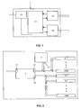
Figur 1- Eine schematische Darstellung der Funktionsblöcke des erfindungsgemäßen Datenkonverters
Figur 2- Eine schematische Darstellung einer Beleuchtungsanlage mit dem erfindungsgemäßen Datenkonverter und einer zentralen Steuervorrichtung
- Figur 3
- Eine schematische Darstellung einer Beleuchtungsanlage mit dem erfindungsgemäßen Datenkonverter und einen Taster als zentrale Steuervorrichtung
- FIG. 1
- A schematic representation of the functional blocks of the data converter according to the invention
- FIG. 2
- A schematic representation of a lighting system with the data converter according to the invention and a central control device
- FIG. 3
- A schematic representation of a lighting system with the data converter according to the invention and a button as a central control device
In
Nachstehend werden zwei unterschiedliche Betriebsverfahren der in
Gemäß des ersten Betriebsmodus des Datenkonverters 1 kommuniziert die zentrale Steuervorrichtung 2 mit dem Datenkonverter 1 auf die gleiche Weise wie mit den ersten Lampenbetriebsmitteln 3.1 bis 3.63. Digitale Steuersignale, die der Datenkonverter 1 an seinem Dateneingang 13 von der zentralen Steuervorrichtung 2 empfängt, werden von der Auswertungseinheit 14 des Datenkonverters 1 ausgewertet und in digitale Kommandos umgewandelt, die über den Datenausgang 13 an alle daran angeschlossenen vierundsechzig zweiten Lampenbetriebsmittel 4.1 bis 4.64 kommuniziert werden. Das heißt, alle zweiten Lampenbetriebsmittel 4.1 bis 4.64 erhalten dieselben Kommandos und deren Leuchtmittel können daher nur simultan ein-, ausgeschaltet und gedimmt werden. Die zweiten Lampenbetriebsmittel 4.1 bis 4.64 sind nicht einzeln, sondern nur als Gruppe ansprechbar und steuerbar. Dementsprechend kann der Datenkonverter 1 eine Statusabfrage der zentralen Steuervorrichtung 2 für die Lampenbetriebsmittel 4.1 bis 4.64 nur gruppenübergreifend beantworten. Im Falle einer defekten Lampe oder eines defekten zweiten Lampenbetriebsmittels 4.1 bis 4.64 wird der Datenkonverter 1 nur das Vorliegen eines Defektes an die zentrale Steuervorrichtung 2 melden, ohne aber die Anzahl der defekten Lampen bzw. Lampenbetriebsmittel 4.1 bis 4.64 feststellen zu können sowie die defekten Lampen bzw. Lampenbetriebsmittel 4.1 bis 4.64 lokalisieren zu können. Individuell ansprechbar und steuerbar sind nur die unmittelbar an die zentrale Steuervorrichtung 2 angeschlossenen ersten Lampenbetriebsmittel 3.1 bis 3.63.According to the first operating mode of the
Der Vorteil des ersten Betriebsmodus ist, dass keine spezielle Inbetriebnahme des Datenkonverters und seiner nachgeschalteten Lampenbetriebsmittel 4.1 bis 4.64 erforderlich ist und der Datenkonverter 1 kompatibel zu allen zentralen Steuervorrichtungen mit DALI-Schnittstelle 21 ist. Nachteilig ist, dass dieser Betriebsmodus keine Gruppeneinteilung der Lampenbetriebsgeräte 4.1 bis 4.64 erlaubt.The advantage of the first mode of operation is that no special commissioning of the data converter and its downstream lamp resources 4.1 to 4.64 is required and the
Auch gemäß des zweiten Betriebsmodus des Datenkonverters 1 kommuniziert die zentrale Steuervorrichtung 2 mit dem Datenkonverter 1 auf die gleiche Weise wie mit den ersten Lampenbetriebsmitteln 3.1 bis 3.63. Digitale Steuersignale, die der Datenkonverter 1 an seinem Dateneingang 13 von der zentralen Steuervorrichtung 2 empfängt, werden von der Auswertungseinheit 14 des Datenkonverters 1 ausgewertet und in digitale Kommandos umgewandelt, die über den Datenausgang 13 aber in der Regel nicht an alle daran angeschlossenen vierundsechzig zweiten Lampenbetriebsmittel 4.1 bis 4.64, sondern selektiv nur an einige vorbestimmte der vierundsechzig zweiten Lampenbetriebsmittel 4.1 bis 4.64 kommuniziert werden. Das heißt, die zweiten Lampenbetriebsmittel 4.1 bis 4.64 werden, im Gegensatz zu dem oben beschriebenen ersten Betriebsmodus, entsprechend ihrer Gruppenzugehörigkeit von der zentralen Steuervorrichtung 2 und dem Datenkonverter 1 gesteuert.Also according to the second operating mode of the
Voraussetzung für die Einteilung der zweiten Lampenbetriebsmittel 4.1 bis 4.64 in Gruppen ist, dass zunächst während einer Inbetriebnahmephase die zweiten Lampenbetriebsmittel 4.1 bis 4.64 mit einem Adressencode versehen werden, um sie für den Datenkonverter 1 und die Steuervorrichtung 2 unterscheidbar zu machen. Idealerweise wird die Inbetriebnahme ohne externen Eingriff vom Datenkonverter 1 automatisch gestartet und durchgeführt, sobald der Datenkonverter 1 Lampenbetriebsmittel ohne Adresse erkennt, die an seinen Datenausgang 13 angeschlossen sind. Alternativ kann diese Inbetriebnahme aber auch über einen am Datenkonverter 1 befindlichen Taster oder über ein spezielles Kommando der zentralen Steuervorrichtung gestartet werden. Der Datenkonverter 1 weist während seiner Inbetriebnahme jedem der Lampenbetriebsmittel 4.1 bis 4.64 einen individuellen Adressencode aus seinem Adressenvorrat zu, den jedes Lampenbetriebsmittel 4.1 bis 4.64 dauerhaft speichert. Durch diesen Adressencode sind die zweiten Lampenbetriebsmittel 4.1 bis 4.64 für den Datenkonverter 1 unterscheidbar. Anschließend wird die Inbetriebnahme der zentralen Steuervorrichtung 2 und der an ihren Steuerausgang 21 angeschlossenen Lampenbetriebsmittel 3.1 bis 3.63 sowie des Datenkonverters 1 gestartet. Die Lampenbetriebsmittel 3.1 bis 3.63 sowie der Datenkonverter 1 werden in maximal sechzehn Gruppen eingeteilt, entsprechend dem verfügbaren Gruppenadressenvorrat der zentralen Steuervorrichtung 2, indem jedem Lampenbetriebsmittel 3.1 bis 3.63 und dem Datenkonverter 1 von der zentralen Steuervorrichtung 2 jeweils mindestens eine der sechzehn Gruppenadressen zugewiesen wird. Die Übernahme des jeweiligen Gruppenadressencodes durch die Lampenbetriebsmittel 3.1 bis 3.63 und 4.1 bis 4.64 kann beispielsweise durch sukzessives Bestücken der Lampenbetriebsmittel 3.1 bis 3.63 und 4.1 bis 4.64 entsprechend ihrer Gruppenzugehörigkeit erreicht werden, wie beispielsweise in der Offenlegungsschrift
Besteht beispielsweise die erste Lampenbetriebsmittelgruppe aus den Lampenbetriebsmitteln 3.1, 4.1 und 4.2, so wird ein für diese Lampenbetriebsmittelgruppe bestimmter Steuerbefehl, von der zentralen Steuervorrichtung 2 über den Steuerausgang 21 an alle erste Lampenbetriebsmittel 3.1 bis 3.63 und über den Datenkonverter 1 an alle zweite Lampenbetriebsmittel 4.1 bis 4.64 gesandt. Allerdings werden nur die Lampenbetriebsmittel 3.1, 4.1 und 4.2 diesen Steuerbefehl ausführen, da nur die von diesen Lampenbetriebsmitteln 3.1, 4.1 und 4.2 gespeicherte Gruppenadresse mit der im Steuerbefehl angegebenen Gruppenadresse übereinstimmt. Der Datenkonverter 1 arbeitet in diesem Fall wie ein Slave, das heißt, er gibt den Steuerbefehl an die an seinem Datenausgang 13 angeschlossenen Lampenbetriebsmittel 4.1 bis 4.64 weiter.A prerequisite for the division of the second lamp resources 4.1 to 4.64 in groups is that initially during a startup phase, the second lamp resources 4.1 to 4.64 are provided with an address code to make them distinguishable for the
If, for example, the first lamp operating group consists of the lamp operating means 3.1, 4.1 and 4.2, a control command determined for this lamp operating group will be sent from the
Bezüglich der an seinen Datenausgang 13 angeschlossenen Lampenbetriebsmittel 4.1 bis 4.64 arbeitet der Datenkonverter 1 hingegen wie ein Master, das heißt beispielsweise, Rückmeldungen der zweiten Lampenbetriebsmittel 4.1 bis 4.64 zu ihrem aktuellen Status auf entsprechende Anfragen der zentralen Steuervorrichtung 2 werden von dem Datenkonverter 1 und nicht von der zentralen Steuervorrichtung 2 ausgewertet. Die zentrale Steuervorrichtung 2 wertet entsprechende Rückmeldungen der ersten Lampenbetriebsmittel 3.1 bis 3.63 aus. Der Datenkonverter 1 führt selbständig durch zyklisches Abfragen der ihm nachgeschalteten Lampenbetriebsmittel 4.1 bis 4.64 eine Statusüberwachung dieser Lampenbetriebsmittel durch. Anhand dieses Statusabbildes kann der Datenkonverter 1 Abfragen der zentralen Steuervorrichtung 2 unmittelbar, ohne Zeitverzögerung beantworten. Ein Durchreichen von Abfragen der zentralen Steuervorrichtung 2 an die dem Datenkonverter 1 nachgeschalteten Lampenbetriebsmittel ist nicht möglich, weil der zeitliche Abstand zwischen einer Abfrage von der zentralen Steuervorrichtung 2 und der Erzeugung einer entsprechenden Rückmeldung der Lampenbetriebsmittel 4.1 bis 4.64 so groß ist, dass der gemäß des DALI-Standards zulässige maximale zeitliche Abstand zwischen der Abfrage und dem Eintreffen der Rückmeldung nicht eingehalten werden kann.With respect to the connected to its
Der Datenkonverter 1 ist auf den ersten Betriebsmodus voreingestellt. Um ihn in den zweiten Betriebsmodus zu versetzen, muss er durch Betätigen eines am Gehäuse des Datenkonverters 1 angeordneten Schalters oder mittels eines speziellen Kommandos der zentralen Steuervorrichtung 2 in diesen umgeschaltet werden. Das Betätigen dieses Schalters oder das vorgenannten Kommando initiiert das oben erläuterte Inbetriebnahmeverfahren.The
Der Datenkonverter 1 ist derart konfiguriert, dass er an seinem Dateneingang 12 sowohl digitale als auch analoge Steuersignale empfangen und auswerten kann. Anstelle der in
Der Dateneingang 12 des Datenkonverters 1 ist über den Taster 5 mit der Netzwechselspannung N, L verbunden. An den Datenausgang 13 des Datenkonverters 1 sind insgesamt vierundsechzig parallel geschaltete Lampenbetriebsmittel 6.1 bis 6.64 angeschlossen. Durch Betätigen des Tasters 5 wird die Verbindung des Dateneingangs 12 zur Netzwechselspannung hergestellt bzw. unterbrochen. Die Auswertungseinheit 14 generiert in Abhängigkeit von der Betätigung des Tasters 5, der Dauer der Tasterbetätigung und dem momentanen Betriebszustand der Lampenbetriebsmittel 6.1 bis 6.64 Steuerbefehle für die an den Datenausgang 13 angeschlossenen Lampenbetriebsmittel 6.1 bis 6.64. Mittels des Tasters 5 werden alle Lampenbetriebsmittel 6.1 bis 6.64 simultan in gleicher Weise gesteuert. Das heißt, die von den Lampenbetriebsmitteln 6.1 bis 6.64 betriebenen Leuchtmittel werden simultan ein- ausgeschaltet und gedimmt. Die Einzelheiten der Steuerung der Lampenbetriebsmittel 6.1 bis 6.64 mittels eines Tasters 5 ist ausführlich in der
Claims (7)
- Method for operating a lighting system that has a number of lamp operating means (3.1-3.63, 4.1-4.64) and a central control device (2) for the lamp operating means (3.1-3.63, 4.1-4.64), first lamp operating means (3.1-3.63) being monitored directly by the central control device (2) and second lamp operating means (4.1-4.64) being monitored and controlled by means of a data converter (1) by virtue of the fact that the control signals generated by the central control device (2) are received and evaluated by the data converter (1) and, as a function of the result of the evaluation, are converted into commands for controlling the lamp operating means (4.1-4.64) monitored by the data converter (1), characterized in that at least two different operating modes are provided for the data converter (1), in accordance with one of these operating modes the control signals generated by the central control device (2) being received and evaluated via the data converter (1) in accordance with a group membership of the second lamp operating means (4.1-4.64) monitored by the data converter (1), which group membership was defined during a start-up phase of the lighting system, and
first of all during the start-up phase a start-up procedure of the data converter (1) is started in order to provide address codes to the second lamp operating means (4.1-4.64) monitored by the data converter (1), and subsequently a start-up procedure of the central control device (2) is started in order to provide address codes to the data converter (1) and to first lamp operating means (3.1-3.63) directly monitored by the central control device (2), the data converter (1) being selected by the central control device (2), for the purpose of grouping the second lamp operating means (4.1-4.64) monitored by the data converter (1), until all the second lamp operating means (4.1-4.64) monitored by the data converter (1) are divided into groups and, upon each selection of the data converter (1), a second lamp operating means (4.1-4.64) monitored by the data converter (1) being successively assigned to a group of lamp operating means. - Method according to Claim 1, characterized in that the data converter (1) automatically carries out a status monitoring of the second lamp operating means (4.1 to 4.64) connected to a data output (13) of the data converter (1).
- Method according to Claim 2, characterized in that the status monitoring of the lamp operating means (4.1 to 4.64) is carried out cyclically at regular time intervals.
- Method according to Claim 2, characterized in that the data converter (1) answers queries from the central control device (2) concerning the status of the lamp operating means (3.1 to 3.63, 4.1 to 4.64) for the second lamp operating means (4.1 to 4.64) connected to the data output (13).
- Method according to Claim 4, characterized in that the data converter (1) answers queries from the central control device (2) concerning the properties of the lamp operating means (3.1 to 3.63, 4.1 to 4.64) for the second lamp operating means (4.1 to 4.64) connected to the data output (13) with a prescribed standard value for the respective interrogated property of the second lamp operating means (4.1 to 4.64) when the second lamp operating means (4.1 to 4.64) differ from one another with reference to the respective interrogated property.
- Method according to Claim 4, characterized in that the data converter (1) answers queries from the central control device (2) concerning the properties of the lamp operating means (3.1 to 3.63, 4.1 to 4.64) for the second lamp operating means (4.1 to 4.64) connected to the data output (13) with a reference value for the respective interrogated property when the second lamp operating means (4.1 to 4.64) are identical with reference to the respective interrogated property, the data converter (1) using as reference value the value of the respective interrogated property of a lamp operating means, selected by the data converter (1), of the second lamp operating means (4.1 to 4.64) connected to the data output (13).
- Data converter (1) for a lighting system for carrying out the method according to one or more of Claims 1 to 6.
Applications Claiming Priority (2)
| Application Number | Priority Date | Filing Date | Title |
|---|---|---|---|
| DE10345611 | 2003-09-29 | ||
| DE10345611A DE10345611A1 (en) | 2003-09-29 | 2003-09-29 | Data converter for a lighting system and method for operating a lighting system |
Publications (2)
| Publication Number | Publication Date |
|---|---|
| EP1519634A1 EP1519634A1 (en) | 2005-03-30 |
| EP1519634B1 true EP1519634B1 (en) | 2009-07-29 |
Family
ID=34178029
Family Applications (1)
| Application Number | Title | Priority Date | Filing Date |
|---|---|---|---|
| EP04019088A Active EP1519634B1 (en) | 2003-09-29 | 2004-08-11 | Dataconverter for a lighting system and method of operation of a lighting system |
Country Status (5)
| Country | Link |
|---|---|
| US (1) | US7259528B2 (en) |
| EP (1) | EP1519634B1 (en) |
| AT (1) | ATE438284T1 (en) |
| CA (1) | CA2482373A1 (en) |
| DE (2) | DE10345611A1 (en) |
Families Citing this family (50)
| Publication number | Priority date | Publication date | Assignee | Title |
|---|---|---|---|---|
| DE10329876B4 (en) * | 2003-07-02 | 2016-06-02 | Tridonic Gmbh & Co Kg | Interface for a lamp operating device with low standby losses and method for driving a lamp operating device via such an interface |
| CA2559153C (en) * | 2005-09-12 | 2018-10-02 | Acuity Brands, Inc. | Light management system having networked intelligent luminaire managers |
| CA2624502C (en) | 2005-10-05 | 2013-07-09 | Guardian Networks, Llc | A method and system for remotely monitoring and controlling field devices with a street lamp elevated mesh network |
| ES2298005B1 (en) * | 2005-11-25 | 2009-02-01 | Lightled, S.A. | STANDS LIGHTING SYSTEM. |
| DE102007013742A1 (en) * | 2007-03-22 | 2008-10-02 | Osram Gesellschaft mit beschränkter Haftung | Operating device and method for the combined operation of gas discharge lamps and semiconductor light sources |
| US8118447B2 (en) | 2007-12-20 | 2012-02-21 | Altair Engineering, Inc. | LED lighting apparatus with swivel connection |
| US7712918B2 (en) | 2007-12-21 | 2010-05-11 | Altair Engineering , Inc. | Light distribution using a light emitting diode assembly |
| US8140276B2 (en) | 2008-02-27 | 2012-03-20 | Abl Ip Holding Llc | System and method for streetlight monitoring diagnostics |
| DE102008017509A1 (en) * | 2008-04-04 | 2009-10-08 | Semperlux Aktiengesellschaft - Lichttechnische Werke - | Installation with DALI bus |
| US8360599B2 (en) | 2008-05-23 | 2013-01-29 | Ilumisys, Inc. | Electric shock resistant L.E.D. based light |
| US7976196B2 (en) | 2008-07-09 | 2011-07-12 | Altair Engineering, Inc. | Method of forming LED-based light and resulting LED-based light |
| US7946729B2 (en) | 2008-07-31 | 2011-05-24 | Altair Engineering, Inc. | Fluorescent tube replacement having longitudinally oriented LEDs |
| US8674626B2 (en) | 2008-09-02 | 2014-03-18 | Ilumisys, Inc. | LED lamp failure alerting system |
| US8256924B2 (en) | 2008-09-15 | 2012-09-04 | Ilumisys, Inc. | LED-based light having rapidly oscillating LEDs |
| US8444292B2 (en) | 2008-10-24 | 2013-05-21 | Ilumisys, Inc. | End cap substitute for LED-based tube replacement light |
| US8653984B2 (en) | 2008-10-24 | 2014-02-18 | Ilumisys, Inc. | Integration of LED lighting control with emergency notification systems |
| US8214084B2 (en) | 2008-10-24 | 2012-07-03 | Ilumisys, Inc. | Integration of LED lighting with building controls |
| US7938562B2 (en) | 2008-10-24 | 2011-05-10 | Altair Engineering, Inc. | Lighting including integral communication apparatus |
| US8324817B2 (en) | 2008-10-24 | 2012-12-04 | Ilumisys, Inc. | Light and light sensor |
| US8901823B2 (en) | 2008-10-24 | 2014-12-02 | Ilumisys, Inc. | Light and light sensor |
| WO2010071913A1 (en) * | 2008-12-22 | 2010-07-01 | Tridonicatco Gmbh & Co Kg | Method for actuating operating devices |
| US8556452B2 (en) | 2009-01-15 | 2013-10-15 | Ilumisys, Inc. | LED lens |
| US8362710B2 (en) | 2009-01-21 | 2013-01-29 | Ilumisys, Inc. | Direct AC-to-DC converter for passive component minimization and universal operation of LED arrays |
| US8664880B2 (en) | 2009-01-21 | 2014-03-04 | Ilumisys, Inc. | Ballast/line detection circuit for fluorescent replacement lamps |
| US8330381B2 (en) | 2009-05-14 | 2012-12-11 | Ilumisys, Inc. | Electronic circuit for DC conversion of fluorescent lighting ballast |
| US8299695B2 (en) | 2009-06-02 | 2012-10-30 | Ilumisys, Inc. | Screw-in LED bulb comprising a base having outwardly projecting nodes |
| WO2011005579A2 (en) | 2009-06-23 | 2011-01-13 | Altair Engineering, Inc. | Illumination device including leds and a switching power control system |
| GB2467196B (en) * | 2009-10-16 | 2011-01-19 | Cp Electronics Ltd | A system for configuring a lighting control device or the like in a network of lighting control devices |
| CA2792940A1 (en) | 2010-03-26 | 2011-09-19 | Ilumisys, Inc. | Led light with thermoelectric generator |
| CA2794512A1 (en) | 2010-03-26 | 2011-09-29 | David L. Simon | Led light tube with dual sided light distribution |
| US8540401B2 (en) | 2010-03-26 | 2013-09-24 | Ilumisys, Inc. | LED bulb with internal heat dissipating structures |
| US8454193B2 (en) | 2010-07-08 | 2013-06-04 | Ilumisys, Inc. | Independent modules for LED fluorescent light tube replacement |
| JP2013531350A (en) | 2010-07-12 | 2013-08-01 | イルミシス,インコーポレイテッド | Circuit board mount for LED arc tube |
| US8523394B2 (en) | 2010-10-29 | 2013-09-03 | Ilumisys, Inc. | Mechanisms for reducing risk of shock during installation of light tube |
| US8870415B2 (en) | 2010-12-09 | 2014-10-28 | Ilumisys, Inc. | LED fluorescent tube replacement light with reduced shock hazard |
| US9072171B2 (en) | 2011-08-24 | 2015-06-30 | Ilumisys, Inc. | Circuit board mount for LED light |
| DE102011054748B4 (en) * | 2011-10-24 | 2017-03-02 | Vossloh-Schwabe Deutschland Gmbh | Control unit for bus-controlled operating devices |
| US9184518B2 (en) | 2012-03-02 | 2015-11-10 | Ilumisys, Inc. | Electrical connector header for an LED-based light |
| DE102012205226A1 (en) * | 2012-03-30 | 2013-10-02 | Zumtobel Lighting Gmbh | Method of operating devices in a lighting system |
| US9163794B2 (en) | 2012-07-06 | 2015-10-20 | Ilumisys, Inc. | Power supply assembly for LED-based light tube |
| US9271367B2 (en) | 2012-07-09 | 2016-02-23 | Ilumisys, Inc. | System and method for controlling operation of an LED-based light |
| US9285084B2 (en) | 2013-03-14 | 2016-03-15 | Ilumisys, Inc. | Diffusers for LED-based lights |
| US9267650B2 (en) | 2013-10-09 | 2016-02-23 | Ilumisys, Inc. | Lens for an LED-based light |
| CN106063381A (en) | 2014-01-22 | 2016-10-26 | 伊卢米斯公司 | LED-based light with addressed LEDs |
| DE102014103527B3 (en) * | 2014-03-14 | 2015-04-30 | Vossloh-Schwabe Deutschland Gmbh | Operating control device and method for generating a status message |
| US9510400B2 (en) | 2014-05-13 | 2016-11-29 | Ilumisys, Inc. | User input systems for an LED-based light |
| US10161568B2 (en) | 2015-06-01 | 2018-12-25 | Ilumisys, Inc. | LED-based light with canted outer walls |
| CN111670608B (en) | 2017-10-25 | 2022-07-15 | 美国尼可有限公司 | Method and system for power supply control |
| USD857979S1 (en) | 2018-03-05 | 2019-08-27 | Intellytech Llc | Foldable light emitting mat |
| USD857980S1 (en) | 2018-04-05 | 2019-08-27 | Intellytech Llc | Foldable light emitting mat |
Family Cites Families (13)
| Publication number | Priority date | Publication date | Assignee | Title |
|---|---|---|---|---|
| US5921659A (en) * | 1993-06-18 | 1999-07-13 | Light & Sound Design, Ltd. | Stage lighting lamp unit and stage lighting system including such unit |
| DE4327809C2 (en) * | 1993-08-18 | 2001-08-09 | Tridonic Bauelemente | Method for addressing electronic ballasts connected to a central control unit |
| US5471119A (en) * | 1994-06-08 | 1995-11-28 | Mti International, Inc. | Distributed control system for lighting with intelligent electronic ballasts |
| CA2198173A1 (en) * | 1997-02-21 | 1998-08-21 | Exacta Transformers Of Canada Ltd. | Micro-controller-operated high intensity discharge lamp ballast system and method |
| US6175771B1 (en) * | 1997-03-03 | 2001-01-16 | Light & Sound Design Ltd. | Lighting communication architecture |
| US6975079B2 (en) * | 1997-08-26 | 2005-12-13 | Color Kinetics Incorporated | Systems and methods for controlling illumination sources |
| US20020113555A1 (en) * | 1997-08-26 | 2002-08-22 | Color Kinetics, Inc. | Lighting entertainment system |
| US6400103B1 (en) * | 1999-03-11 | 2002-06-04 | Power Circuit Innovations, Inc. | Networkable power controller |
| ATE332624T1 (en) * | 2000-01-14 | 2006-07-15 | Patent Treuhand Ges Fuer Elektrische Gluehlampen Mbh | DEVICE AND METHOD FOR CONTROLLING EQUIPMENT FOR AT LEAST ONE ELECTRICAL LAMP |
| US7202613B2 (en) * | 2001-05-30 | 2007-04-10 | Color Kinetics Incorporated | Controlled lighting methods and apparatus |
| US6507158B1 (en) | 2000-11-15 | 2003-01-14 | Koninkljke Philips Electronics N.V. | Protocol enhancement for lighting control networks and communications interface for same |
| US20030036807A1 (en) * | 2001-08-14 | 2003-02-20 | Fosler Ross M. | Multiple master digital addressable lighting interface (DALI) system, method and apparatus |
| US6859644B2 (en) * | 2002-03-13 | 2005-02-22 | Koninklijke Philips Electronics N.V. | Initialization of wireless-controlled lighting systems |
-
2003
- 2003-09-29 DE DE10345611A patent/DE10345611A1/en not_active Withdrawn
-
2004
- 2004-08-11 EP EP04019088A patent/EP1519634B1/en active Active
- 2004-08-11 DE DE502004009811T patent/DE502004009811D1/en active Active
- 2004-08-11 AT AT04019088T patent/ATE438284T1/en active
- 2004-09-14 US US10/939,350 patent/US7259528B2/en active Active
- 2004-09-23 CA CA002482373A patent/CA2482373A1/en not_active Abandoned
Also Published As
| Publication number | Publication date |
|---|---|
| ATE438284T1 (en) | 2009-08-15 |
| US7259528B2 (en) | 2007-08-21 |
| DE10345611A1 (en) | 2005-04-21 |
| US20050067982A1 (en) | 2005-03-31 |
| DE502004009811D1 (en) | 2009-09-10 |
| CA2482373A1 (en) | 2005-03-29 |
| EP1519634A1 (en) | 2005-03-30 |
Similar Documents
| Publication | Publication Date | Title |
|---|---|---|
| EP1519634B1 (en) | Dataconverter for a lighting system and method of operation of a lighting system | |
| EP1480495B1 (en) | Lighting equipment and method for installing it | |
| WO1999048251A1 (en) | Method for commissioning a bus system and corresponding bus system | |
| DE10344619B4 (en) | Control system for a plurality of distributed lamp operating devices and method for initializing such a control system | |
| EP2364574B1 (en) | Address assignment for bus-capable lighting-means operating devices particularly for leds | |
| EP2044814A1 (en) | Switchgear, system for controlling a lamp, and light control system for a building comprising at least one light | |
| DE102005028206A1 (en) | Method for determining bus address of bus subscriber in illuminating bus system involves illuminating of operating device, which comprises additional optical and acoustic signal emitters in addition to the illuminating means | |
| EP2312913B1 (en) | Control system for several separately arranged consumers, especially lamp operating devices, and start-up method | |
| DE102008001942B3 (en) | Mobile heating system | |
| EP1292175B1 (en) | Light system management with electronic starter | |
| EP1035755B1 (en) | Method for installing the electrical operating means of a lighting system | |
| DE112012001781B4 (en) | LED lighting system and addressing method for an LED lighting system | |
| EP2359579B1 (en) | Addressing method for a lamp, particularly light-emitting diodes | |
| EP3251469A1 (en) | Method for operating devices in a lighting system | |
| EP1331533B1 (en) | Process of allocating user addresses in a control system for a plurality of actuators | |
| EP1530108B1 (en) | Electric/electronic control system | |
| DE102018000893A1 (en) | Method for controlling luminaires provided with at least one detector unit within at least one room and system for carrying out the method | |
| DE102012210833B4 (en) | Method for configuring a lighting system | |
| DE102010032712B3 (en) | Building automation system configuration method for controlling e.g. illumination devices within residential- or commercial building, involves transmitting confirmation about switch-on state of actuators to building automation system | |
| EP2425683B1 (en) | Interface for a lighting system | |
| WO2008040390A1 (en) | Lighting system and method for operating a lighting system | |
| EP3731042B1 (en) | Electric/electronic installation system | |
| AT12594U1 (en) | INTERFACE FOR A BULB OPERATING DEVICE | |
| DE102018000006A1 (en) | Bus system and master unit for use in a bus system | |
| WO2007121723A1 (en) | Lighting control system |
Legal Events
| Date | Code | Title | Description |
|---|---|---|---|
| PUAI | Public reference made under article 153(3) epc to a published international application that has entered the european phase |
Free format text: ORIGINAL CODE: 0009012 |
|
| 17P | Request for examination filed |
Effective date: 20041118 |
|
| AK | Designated contracting states |
Kind code of ref document: A1 Designated state(s): AT BE BG CH CY CZ DE DK EE ES FI FR GB GR HU IE IT LI LU MC NL PL PT RO SE SI SK TR |
|
| AX | Request for extension of the european patent |
Extension state: AL HR LT LV MK |
|
| AKX | Designation fees paid |
Designated state(s): AT BE BG CH CY CZ DE DK EE ES FI FR GB GR HU IE IT LI LU MC NL PL PT RO SE SI SK TR |
|
| 17Q | First examination report despatched |
Effective date: 20051221 |
|
| GRAP | Despatch of communication of intention to grant a patent |
Free format text: ORIGINAL CODE: EPIDOSNIGR1 |
|
| RAP1 | Party data changed (applicant data changed or rights of an application transferred) |
Owner name: OSRAM GESELLSCHAFT MIT BESCHRAENKTER HAFTUNG |
|
| GRAS | Grant fee paid |
Free format text: ORIGINAL CODE: EPIDOSNIGR3 |
|
| GRAA | (expected) grant |
Free format text: ORIGINAL CODE: 0009210 |
|
| AK | Designated contracting states |
Kind code of ref document: B1 Designated state(s): AT BE BG CH CY CZ DE DK EE ES FI FR GB GR HU IE IT LI LU MC NL PL PT RO SE SI SK TR |
|
| REG | Reference to a national code |
Ref country code: GB Ref legal event code: FG4D Free format text: NOT ENGLISH |
|
| REG | Reference to a national code |
Ref country code: CH Ref legal event code: EP Ref country code: CH Ref legal event code: NV Representative=s name: SIEMENS SCHWEIZ AG |
|
| REG | Reference to a national code |
Ref country code: IE Ref legal event code: FG4D |
|
| REF | Corresponds to: |
Ref document number: 502004009811 Country of ref document: DE Date of ref document: 20090910 Kind code of ref document: P |
|
| NLV1 | Nl: lapsed or annulled due to failure to fulfill the requirements of art. 29p and 29m of the patents act | ||
| PG25 | Lapsed in a contracting state [announced via postgrant information from national office to epo] |
Ref country code: SE Free format text: LAPSE BECAUSE OF FAILURE TO SUBMIT A TRANSLATION OF THE DESCRIPTION OR TO PAY THE FEE WITHIN THE PRESCRIBED TIME-LIMIT Effective date: 20090729 Ref country code: ES Free format text: LAPSE BECAUSE OF FAILURE TO SUBMIT A TRANSLATION OF THE DESCRIPTION OR TO PAY THE FEE WITHIN THE PRESCRIBED TIME-LIMIT Effective date: 20091109 Ref country code: FI Free format text: LAPSE BECAUSE OF FAILURE TO SUBMIT A TRANSLATION OF THE DESCRIPTION OR TO PAY THE FEE WITHIN THE PRESCRIBED TIME-LIMIT Effective date: 20090729 |
|
| PG25 | Lapsed in a contracting state [announced via postgrant information from national office to epo] |
Ref country code: SI Free format text: LAPSE BECAUSE OF FAILURE TO SUBMIT A TRANSLATION OF THE DESCRIPTION OR TO PAY THE FEE WITHIN THE PRESCRIBED TIME-LIMIT Effective date: 20090729 Ref country code: NL Free format text: LAPSE BECAUSE OF FAILURE TO SUBMIT A TRANSLATION OF THE DESCRIPTION OR TO PAY THE FEE WITHIN THE PRESCRIBED TIME-LIMIT Effective date: 20090729 Ref country code: PL Free format text: LAPSE BECAUSE OF FAILURE TO SUBMIT A TRANSLATION OF THE DESCRIPTION OR TO PAY THE FEE WITHIN THE PRESCRIBED TIME-LIMIT Effective date: 20090729 |
|
| BERE | Be: lapsed |
Owner name: OSRAM G.M.B.H. Effective date: 20090831 |
|
| REG | Reference to a national code |
Ref country code: IE Ref legal event code: FD4D |
|
| PG25 | Lapsed in a contracting state [announced via postgrant information from national office to epo] |
Ref country code: PT Free format text: LAPSE BECAUSE OF FAILURE TO SUBMIT A TRANSLATION OF THE DESCRIPTION OR TO PAY THE FEE WITHIN THE PRESCRIBED TIME-LIMIT Effective date: 20091129 Ref country code: BG Free format text: LAPSE BECAUSE OF FAILURE TO SUBMIT A TRANSLATION OF THE DESCRIPTION OR TO PAY THE FEE WITHIN THE PRESCRIBED TIME-LIMIT Effective date: 20091029 Ref country code: MC Free format text: LAPSE BECAUSE OF NON-PAYMENT OF DUE FEES Effective date: 20090831 |
|
| PG25 | Lapsed in a contracting state [announced via postgrant information from national office to epo] |
Ref country code: DK Free format text: LAPSE BECAUSE OF FAILURE TO SUBMIT A TRANSLATION OF THE DESCRIPTION OR TO PAY THE FEE WITHIN THE PRESCRIBED TIME-LIMIT Effective date: 20090729 Ref country code: RO Free format text: LAPSE BECAUSE OF FAILURE TO SUBMIT A TRANSLATION OF THE DESCRIPTION OR TO PAY THE FEE WITHIN THE PRESCRIBED TIME-LIMIT Effective date: 20090729 Ref country code: EE Free format text: LAPSE BECAUSE OF FAILURE TO SUBMIT A TRANSLATION OF THE DESCRIPTION OR TO PAY THE FEE WITHIN THE PRESCRIBED TIME-LIMIT Effective date: 20090729 Ref country code: IE Free format text: LAPSE BECAUSE OF FAILURE TO SUBMIT A TRANSLATION OF THE DESCRIPTION OR TO PAY THE FEE WITHIN THE PRESCRIBED TIME-LIMIT Effective date: 20090729 Ref country code: CZ Free format text: LAPSE BECAUSE OF FAILURE TO SUBMIT A TRANSLATION OF THE DESCRIPTION OR TO PAY THE FEE WITHIN THE PRESCRIBED TIME-LIMIT Effective date: 20090729 |
|
| PG25 | Lapsed in a contracting state [announced via postgrant information from national office to epo] |
Ref country code: SK Free format text: LAPSE BECAUSE OF FAILURE TO SUBMIT A TRANSLATION OF THE DESCRIPTION OR TO PAY THE FEE WITHIN THE PRESCRIBED TIME-LIMIT Effective date: 20090729 |
|
| PLBE | No opposition filed within time limit |
Free format text: ORIGINAL CODE: 0009261 |
|
| STAA | Information on the status of an ep patent application or granted ep patent |
Free format text: STATUS: NO OPPOSITION FILED WITHIN TIME LIMIT |
|
| PG25 | Lapsed in a contracting state [announced via postgrant information from national office to epo] |
Ref country code: BE Free format text: LAPSE BECAUSE OF NON-PAYMENT OF DUE FEES Effective date: 20090831 |
|
| 26N | No opposition filed |
Effective date: 20100503 |
|
| PG25 | Lapsed in a contracting state [announced via postgrant information from national office to epo] |
Ref country code: GR Free format text: LAPSE BECAUSE OF FAILURE TO SUBMIT A TRANSLATION OF THE DESCRIPTION OR TO PAY THE FEE WITHIN THE PRESCRIBED TIME-LIMIT Effective date: 20091030 |
|
| PG25 | Lapsed in a contracting state [announced via postgrant information from national office to epo] |
Ref country code: IT Free format text: LAPSE BECAUSE OF FAILURE TO SUBMIT A TRANSLATION OF THE DESCRIPTION OR TO PAY THE FEE WITHIN THE PRESCRIBED TIME-LIMIT Effective date: 20090729 |
|
| PG25 | Lapsed in a contracting state [announced via postgrant information from national office to epo] |
Ref country code: LU Free format text: LAPSE BECAUSE OF NON-PAYMENT OF DUE FEES Effective date: 20090811 |
|
| PG25 | Lapsed in a contracting state [announced via postgrant information from national office to epo] |
Ref country code: HU Free format text: LAPSE BECAUSE OF FAILURE TO SUBMIT A TRANSLATION OF THE DESCRIPTION OR TO PAY THE FEE WITHIN THE PRESCRIBED TIME-LIMIT Effective date: 20100130 |
|
| PG25 | Lapsed in a contracting state [announced via postgrant information from national office to epo] |
Ref country code: TR Free format text: LAPSE BECAUSE OF FAILURE TO SUBMIT A TRANSLATION OF THE DESCRIPTION OR TO PAY THE FEE WITHIN THE PRESCRIBED TIME-LIMIT Effective date: 20090729 |
|
| PG25 | Lapsed in a contracting state [announced via postgrant information from national office to epo] |
Ref country code: CY Free format text: LAPSE BECAUSE OF FAILURE TO SUBMIT A TRANSLATION OF THE DESCRIPTION OR TO PAY THE FEE WITHIN THE PRESCRIBED TIME-LIMIT Effective date: 20090729 |
|
| PGFP | Annual fee paid to national office [announced via postgrant information from national office to epo] |
Ref country code: AT Payment date: 20110712 Year of fee payment: 8 |
|
| REG | Reference to a national code |
Ref country code: DE Ref legal event code: R081 Ref document number: 502004009811 Country of ref document: DE Owner name: OSRAM GMBH, DE Free format text: FORMER OWNER: OSRAM GESELLSCHAFT MIT BESCHRAENKTER HAFTUNG, 81543 MUENCHEN, DE Effective date: 20111213 |
|
| REG | Reference to a national code |
Ref country code: DE Ref legal event code: R081 Ref document number: 502004009811 Country of ref document: DE Owner name: OSRAM GMBH, DE Free format text: FORMER OWNER: OSRAM AG, 81543 MUENCHEN, DE Effective date: 20130205 |
|
| REG | Reference to a national code |
Ref country code: AT Ref legal event code: MM01 Ref document number: 438284 Country of ref document: AT Kind code of ref document: T Effective date: 20120811 |
|
| PG25 | Lapsed in a contracting state [announced via postgrant information from national office to epo] |
Ref country code: AT Free format text: LAPSE BECAUSE OF NON-PAYMENT OF DUE FEES Effective date: 20120811 |
|
| REG | Reference to a national code |
Ref country code: DE Ref legal event code: R081 Ref document number: 502004009811 Country of ref document: DE Owner name: OSRAM GMBH, DE Free format text: FORMER OWNER: OSRAM GMBH, 81543 MUENCHEN, DE Effective date: 20130823 |
|
| PGFP | Annual fee paid to national office [announced via postgrant information from national office to epo] |
Ref country code: GB Payment date: 20140820 Year of fee payment: 11 |
|
| GBPC | Gb: european patent ceased through non-payment of renewal fee |
Effective date: 20150811 |
|
| PG25 | Lapsed in a contracting state [announced via postgrant information from national office to epo] |
Ref country code: GB Free format text: LAPSE BECAUSE OF NON-PAYMENT OF DUE FEES Effective date: 20150811 |
|
| REG | Reference to a national code |
Ref country code: FR Ref legal event code: PLFP Year of fee payment: 13 |
|
| REG | Reference to a national code |
Ref country code: FR Ref legal event code: PLFP Year of fee payment: 14 |
|
| REG | Reference to a national code |
Ref country code: FR Ref legal event code: PLFP Year of fee payment: 15 |
|
| REG | Reference to a national code |
Ref country code: DE Ref legal event code: R081 Ref document number: 502004009811 Country of ref document: DE Owner name: INVENTRONICS GMBH, DE Free format text: FORMER OWNER: OSRAM GMBH, 80807 MUENCHEN, DE Ref country code: DE Ref legal event code: R081 Ref document number: 502004009811 Country of ref document: DE Owner name: OPTOTRONIC GMBH, DE Free format text: FORMER OWNER: OSRAM GMBH, 80807 MUENCHEN, DE |
|
| REG | Reference to a national code |
Ref country code: DE Ref legal event code: R081 Ref document number: 502004009811 Country of ref document: DE Owner name: INVENTRONICS GMBH, DE Free format text: FORMER OWNER: OPTOTRONIC GMBH, 85748 GARCHING, DE |
|
| PGFP | Annual fee paid to national office [announced via postgrant information from national office to epo] |
Ref country code: CH Payment date: 20230902 Year of fee payment: 20 |
|
| PGFP | Annual fee paid to national office [announced via postgrant information from national office to epo] |
Ref country code: FR Payment date: 20230821 Year of fee payment: 20 Ref country code: DE Payment date: 20230831 Year of fee payment: 20 |