EP1619935A2 - Element lumineux de secours avec interface de commande numérique - Google Patents
Element lumineux de secours avec interface de commande numérique Download PDFInfo
- Publication number
- EP1619935A2 EP1619935A2 EP05014709A EP05014709A EP1619935A2 EP 1619935 A2 EP1619935 A2 EP 1619935A2 EP 05014709 A EP05014709 A EP 05014709A EP 05014709 A EP05014709 A EP 05014709A EP 1619935 A2 EP1619935 A2 EP 1619935A2
- Authority
- EP
- European Patent Office
- Prior art keywords
- emergency light
- normal operation
- light element
- electronic ballast
- ecg
- Prior art date
- Legal status (The legal status is an assumption and is not a legal conclusion. Google has not performed a legal analysis and makes no representation as to the accuracy of the status listed.)
- Granted
Links
- 238000011990 functional testing Methods 0.000 claims description 6
- 238000002565 electrocardiography Methods 0.000 description 45
- 238000004891 communication Methods 0.000 description 2
- 239000004020 conductor Substances 0.000 description 2
- 230000007935 neutral effect Effects 0.000 description 2
- 230000002349 favourable effect Effects 0.000 description 1
- 238000004519 manufacturing process Methods 0.000 description 1
- 238000000034 method Methods 0.000 description 1
- 238000012544 monitoring process Methods 0.000 description 1
- 230000005405 multipole Effects 0.000 description 1
- 230000001960 triggered effect Effects 0.000 description 1
Images


Classifications
-
- H—ELECTRICITY
- H02—GENERATION; CONVERSION OR DISTRIBUTION OF ELECTRIC POWER
- H02J—CIRCUIT ARRANGEMENTS OR SYSTEMS FOR SUPPLYING OR DISTRIBUTING ELECTRIC POWER; SYSTEMS FOR STORING ELECTRIC ENERGY
- H02J9/00—Circuit arrangements for emergency or stand-by power supply, e.g. for emergency lighting
- H02J9/02—Circuit arrangements for emergency or stand-by power supply, e.g. for emergency lighting in which an auxiliary distribution system and its associated lamps are brought into service
-
- H—ELECTRICITY
- H05—ELECTRIC TECHNIQUES NOT OTHERWISE PROVIDED FOR
- H05B—ELECTRIC HEATING; ELECTRIC LIGHT SOURCES NOT OTHERWISE PROVIDED FOR; CIRCUIT ARRANGEMENTS FOR ELECTRIC LIGHT SOURCES, IN GENERAL
- H05B47/00—Circuit arrangements for operating light sources in general, i.e. where the type of light source is not relevant
- H05B47/10—Controlling the light source
- H05B47/175—Controlling the light source by remote control
- H05B47/18—Controlling the light source by remote control via data-bus transmission
Definitions
- the present invention relates to an emergency light element having a digitally addressable control interface.
- emergency lighting elements are provided in addition to electronic ballasts for normal operation, such as ballasts, the low-pressure discharge lamps can operate on household mains voltage.
- These emergency lighting elements are intended for safety reasons in the event of failure of the mains supply and therefore have a battery or a battery connection and a device for detecting the emergency light case, d. H. of the power supply failure, on.
- the battery is integrated.
- a ballast for operating a lamp is provided on the battery, which is put into operation in case of emergency. This then operates a specially provided for this purpose or even used in normal operation case lamp and thus provides emergency lighting.
- Such emergency lighting elements are known per se, in particular as complete lights with the lamp to be operated in the emergency light case.
- the present invention is therefore based on the technical problem of providing an advantageous emergency light element which is well suited for use in a digitally controlled lighting system.
- the invention is directed to an emergency light element with a battery connection, a device for detecting a power supply failure and designed for the battery operation of a lamp electronic ballast, characterized in that the emergency light element has a digitally addressable control interface and a control output for an electronic ballast for normal operation and to is designed to control the electronic ballast for normal operation in normal operation via the digitally addressable control interface.
- the invention therefore provides to equip an emergency light element on the one hand with a digitally addressable control interface, but also to provide a control output for an electronic ballast for normal operation (hereinafter for the sake of brevity normal ECG). So it is a control of a normal operation ECG on the provided emergency light element according to the invention. This can be dispensed with a separate digitally addressable control interface of the normal operation ECG, so that a certain technical effort, but especially a digital address, can be saved.
- the emergency light element has a connection for a lamp to be operated in an emergency light case, which can be connected to the electronic ballast designed for battery operation within the emergency light element. Furthermore, however, the emergency light element here also has a connection for the normal operation ECG, via which this lamp can operate in normal operation. It is therefore switched in the emergency light case of lamp operation by the normal operation ECG to the "emergency ECG" within the emergency light element.
- the lamp is integrated, so it is a total of an emergency light.
- the normal operation ECG is integrated. This is either a combined normal / emergency light or, if no lamp is integrated, a combined normal / emergency ECG.
- the invention also relates to embodiments in which the lamp and / or the normal operation ECG are provided externally and can be connected to the emergency light element only.
- control output here includes not only exclusive control signal outputs, but also outputs that have, inter alia, control functions, ie control operations of the emergency light element output.
- control output can be a supply output, such as a phase output, which can be switched off in a controlled manner within the emergency light element even if the mains supply continues to be present. This should apply even in the event that the emergency light element, as preferred, has an input for an externally connected mains supply (in particular phase).
- the shutdown of this supply output for the normal operation ECG is in response to control signals received via the digitally addressable interface.
- the emergency light element may be used within (at least in part) digitally controlled lighting systems along with a conventional normal operation ECG that itself is not digitally addressable.
- This normal operation ECG can then be switched on and off, for example, via the already mentioned externally switched phase, which however is connected via the emergency light element.
- the emergency light element can switch off this supply of the normal operation ECG in response to digital control signals.
- the digital control running functional tests of the emergency light functions in which then the or the normal operation ECG must be turned off, although the actual mains supply is still available.
- the control output is a separate digital output.
- the normal operation electronic ballast which in this case also has a digitally addressable interface of an identical or compatible type.
- the emergency light element generates different kind of digital control signals and outputs to the normal operation ECG.
- these are preferably internally of relevance to the Emergency light element self-tested.
- the emergency light element can interrogate certain operating and configuration parameters of the normal operation ECG periodically and store it in an internal memory in order to be able to answer queries about the state of the normal operation electronic ballast without or with a slight time delay.
- the emergency light element according to the invention can also be combined with a plurality of normal operation ECGs, whether they are integrated or external. These can also be controlled via one and the same control output, in the case of the separate digital control output thus in the sense of a bus line and in the case of the control output switching control output in the sense of a parallel connection.
- the emergency light element preferably has further connections for a functional test device which is connected locally in order to test the individual emergency light element. Where this is required, a local test and display option can be realized.
- the invention is directed to electronic ballasts in the most general sense, so on any form of operating devices for lamps.
- ECGs for low-pressure discharge lamps for example in tubular form or as so-called energy-saving lamps.
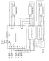
- FIG. 1 shows an emergency light element according to the invention in a particularly simple application situation.
- the emergency light element is in this embodiment part of an emergency light and operates the right-drawn tubular low-pressure discharge lamp type FH 14W. It also contains a not-shown in Figure 1 emergency ECG and a top left battery connected to the same supply.
- the emergency light bulb is operated via lamp terminals with the designation lamps 1 to 4 and used in the application shown here only as an emergency light bulb.
- DA In the left upper area are marked with DA designated terminals, which are differentiated by DA system and DA ECG.
- the DA system is connected to external lines, namely control signal lines of a digital central control system. This is the control of a larger lighting system, which controls the connected devices according to the so-called DALI standard (digital addressable lighting interface) via respective digitally addressable interfaces.
- DALI digital addressable lighting interface
- the emergency light element contains supply lines, namely a phase L, a neutral conductor N and a ground PE, which are connected to identical connections.
- supply lines namely a phase L, a neutral conductor N and a ground PE, which are connected to identical connections.
- the importance of the unused connections L 'and L Q will be discussed in more detail.
- connection designated RJ11 is provided at the top in the center, which serves to connect an external test device for local functional tests of the emergency light element.
- the tester is shown with a switch symbol and a light-emitting diode symbol.
- the emergency light element is additionally connected via the terminals ECG 1-4 with a dimmable normal operation ECG for two 54W lamps, here the type QT FQ 2x54 DIM.
- This normal operation electronic ballast can operate the already mentioned emergency light bulb in normal operation via the connections ECG 1-4. Furthermore, the normal operation ECG can be a right next to him drawn additional lamp operate the same type, which is not operated in an emergency light case. So it is a two-lamp with emergency light function.
- This conventional ECG is supplied on the one hand directly via the neutral conductor N from the mains supply and on the other hand via the phase output L Q of the emergency light element.
- the phase output L Q is switchably connected to the phase input L 'of the emergency light element, which is supplied via the line L SW .
- This is an externally switched phase, which can thus be switched off in contrast to the continuous supply phase L in order to control the mentioned normal operation ECG.
- the internal connection between the terminals L 'and L Q in the emergency light element is switchable, so that a digital control signal (for example via the terminals DA system) can open the connection between L' and L Q.
- the normal operation ECG can therefore be switched off, even though there is no emergency light case, ie the continuous phase L is active, and moreover not even the externally switched phase L SW was switched off externally.
- This can be simulated via the digital control in the emergency light element emergency lighting case without the normal operation ECG would have to implement the digital control signals themselves.
- a further analogue connection of the normal operation electronic ballast is also shown, which may be, for example, a dimming control terminal.
- This example thus shows in particular a two-lamp emergency light in a lighting system with a mixed digital / analog control.
- the control output for controlling the normal operation ECG is the switched phase output L Q which can be switched off by the emergency light element independently of the phase input L or L 'when corresponding control signals are received via the digitally addressable DA system interface.
- FIG. 3 shows the emergency light element from the previous figures together with another additional normal operation ECG. So it may be a total of a three-lamp with emergency light function or it could be the third ECG connected as an external ECG to a two-lamp with emergency light function.
- both normal-mode ECGs specifically of the type QT DALI FQ 2x54 or QT DALI FQ 1x54
- the luminaire including the potentially external third electronic ballast
- All DALI commands are passed from the emergency light element to the DALI ECG.
- the commands received by the digital control unit of the system must be interpreted by the emergency light element and partially executed by itself.
- the emergency light element In order to be able to correctly answer status queries of the control unit on the one hand and queries of the DALI ECG on the other hand, the emergency light element must also store the received control commands and periodically determine and save the status of the downstream ECGs.
- the emergency light-specific DALI commands must be processed and the battery condition and the mains voltage constantly monitored.
- the emergency light element thus has the function of a DALI-controlled emergency light element with integrated control unit for further DALI ECGs.
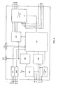
- FIG. 4 shows the internal structure of the emergency light element from FIGS. 1-3.
- the designation of the connections corresponds to the mentioned figures.
- the individual function blocks essentially have the following function:
- the digitally addressable interface is designated DS1.
- Another digital interface DS2 is used for communication with the DALI ECGs.
- the block PS generates the internal supply voltages from the already mentioned mains supply.
- the block BM contains the charging and monitoring electronics for the battery management and is therefore connected on the one hand to the block PS and the other to the battery terminal BAT.
- the abbreviation NM stands for network monitor. This monitors the applied mains voltage and thus detects the presence of an emergency light situation. The network monitor also detects the state of the switched network input L '. The monitored functions are forwarded to the digital sequencer AS described below.
- the block MS switches the supply voltage of the connected in Figure 2 to the terminal L Q EVG, thus forms the switch between the terminals L 'and L Q and is controlled by the sequence controller AS.
- WR stands for an inverter, namely an ECG optimized for battery operation for the operation of the connected low-pressure discharge lamp (eg FQ 54W) in the event of an emergency, possibly with reduced power. Therefore, the inverter is connected to the battery terminal BAT and, on the other hand, is controlled by the sequence controller AS.
- the inverter is connected to the battery terminal BAT and, on the other hand, is controlled by the sequence controller AS.
- LS designates a multi-pole changeover switch which decouples the lamp connected on the top right in the emergency light mode from the normal operating ECG connected to the connections EVG 1-4 and connects it to the inverter WR.
- AS designates the central digital sequence control, which contains, among other things, the software elements necessary for digital DALI communication, necessary clocks, and a decision logic for switching between normal and emergency lighting operation.
- the emergency light element of Figure 4 can be used in the manner illustrated in Figures 1-3 for controlling normal operation electronic ballast and occupies only one digital address in each case. It allows in all cases triggered and monitored by centralized digital control, including the creation of result logs, as required in some cases. Furthermore, the tests can also be performed "manually" on the individual luminaires via the additional RJ11 connection, and their results can be displayed locally.
- the normal operation ECGs can be external or integrated. The same applies to the low-pressure discharge lamps.
Applications Claiming Priority (1)
| Application Number | Priority Date | Filing Date | Title |
|---|---|---|---|
| DE102004035678A DE102004035678A1 (de) | 2004-07-22 | 2004-07-22 | Notlichtvorschaltelement mit digital adressierbarer Steuerschnittstelle |
Publications (3)
| Publication Number | Publication Date |
|---|---|
| EP1619935A2 true EP1619935A2 (fr) | 2006-01-25 |
| EP1619935A3 EP1619935A3 (fr) | 2006-07-12 |
| EP1619935B1 EP1619935B1 (fr) | 2007-11-28 |
Family
ID=35115972
Family Applications (1)
| Application Number | Title | Priority Date | Filing Date |
|---|---|---|---|
| EP05014709A Active EP1619935B1 (fr) | 2004-07-22 | 2005-07-06 | Element lumineux de secours avec interface de commande numérique |
Country Status (7)
| Country | Link |
|---|---|
| US (1) | US20060018107A1 (fr) |
| EP (1) | EP1619935B1 (fr) |
| CN (1) | CN1758824B (fr) |
| AT (1) | ATE379951T1 (fr) |
| CA (1) | CA2512331A1 (fr) |
| DE (2) | DE102004035678A1 (fr) |
| ES (1) | ES2294599T3 (fr) |
Cited By (5)
| Publication number | Priority date | Publication date | Assignee | Title |
|---|---|---|---|---|
| DE102005034730B3 (de) * | 2005-07-21 | 2007-02-01 | Siemens Ag | Verfahren um Erfassen einer Zugehörigkeit eines Notlichtversorgungsgeräts zu einem elektronischen Vorschaltgeräts in einem DALI-Netzwerk |
| EP1954105A1 (fr) * | 2007-01-29 | 2008-08-06 | TridonicAtco GmbH & Co. KG | Procédé et système de transmission de données dans des appareils de fonctionnement pour moyens d'éclairage |
| WO2009033471A2 (fr) * | 2007-09-12 | 2009-03-19 | P.E.R. Flucht- Und Rettungsleitsysteme Gmbh | Procédé et système d'éclairage de secours |
| EP2782212A1 (fr) * | 2013-03-22 | 2014-09-24 | Zumtobel Lighting GmbH | Système d'éclairage et lampe avec fonction d'éclairage de secours |
| ITUB20153885A1 (it) * | 2015-09-25 | 2017-03-25 | Zetaqulab Srl | Sistema ed apparato di gestione dell'illuminazione |
Families Citing this family (3)
| Publication number | Priority date | Publication date | Assignee | Title |
|---|---|---|---|---|
| CN201069088Y (zh) * | 2007-08-06 | 2008-06-04 | 巴力士照明有限公司 | 一种应急照明装置 |
| DE102012220760A1 (de) * | 2012-11-14 | 2014-05-15 | Bag Engineering Gmbh | Multifunktionales Betriebsgerät zum Versorgen eines Verbrauchers wie eines LED-Moduls sowie Verfahren zu dessen Betrieb |
| DE102014103527B3 (de) * | 2014-03-14 | 2015-04-30 | Vossloh-Schwabe Deutschland Gmbh | Betriebssteuergerät und Verfahren zur Erzeugung einer Statusmeldung |
Citations (3)
| Publication number | Priority date | Publication date | Assignee | Title |
|---|---|---|---|---|
| EP0433527A1 (fr) * | 1989-12-21 | 1991-06-26 | Zumtobel Aktiengesellschaft | Dispositif de commande pour plusieurs utilisateurs |
| WO2000027013A1 (fr) * | 1998-10-30 | 2000-05-11 | Lumatec Sa | Element lumineux de secours pour actionner des lampes fluorescentes en cas de panne de secteur |
| DE10344619A1 (de) * | 2003-09-25 | 2005-04-21 | Luxmate Controls Gmbh Dornbirn | Steuersystem für mehrere verteilt angeordnete Lampenbetriebsgeräte sowie Verfahren zum Initialisieren eines derartigen Steuersystems |
Family Cites Families (7)
| Publication number | Priority date | Publication date | Assignee | Title |
|---|---|---|---|---|
| US5633564A (en) * | 1995-06-01 | 1997-05-27 | Edwards; M. Larry | Modular uninterruptible lighting system |
| US5734229A (en) * | 1995-11-29 | 1998-03-31 | Bavaro; Joseph P. | Back-up electrical system for portable table lamps |
| DE10006408A1 (de) * | 2000-02-14 | 2001-08-16 | Zumtobel Staff Gmbh | Beleuchtungssystem |
| US6577136B1 (en) * | 2002-04-23 | 2003-06-10 | Acuity Brands, Inc. | Modular self-diagnostic and test switch assembly for controlling inverter operations |
| US7009348B2 (en) * | 2002-06-03 | 2006-03-07 | Systel Development & Industries Ltd. | Multiple channel ballast and networkable topology and system including power line carrier applications |
| US6929376B2 (en) * | 2002-11-26 | 2005-08-16 | W. F. Harris Lighting, Inc. | Systems, devices and methods for lighting |
| US7086747B2 (en) * | 2002-12-11 | 2006-08-08 | Safeexit, Inc. | Low-voltage lighting apparatus for satisfying after-hours lighting requirements, emergency lighting requirements, and low light requirements |
-
2004
- 2004-07-22 DE DE102004035678A patent/DE102004035678A1/de not_active Withdrawn
-
2005
- 2005-07-06 AT AT05014709T patent/ATE379951T1/de not_active IP Right Cessation
- 2005-07-06 DE DE502005002080T patent/DE502005002080D1/de active Active
- 2005-07-06 EP EP05014709A patent/EP1619935B1/fr active Active
- 2005-07-06 ES ES05014709T patent/ES2294599T3/es active Active
- 2005-07-12 US US11/178,369 patent/US20060018107A1/en not_active Abandoned
- 2005-07-18 CA CA002512331A patent/CA2512331A1/fr not_active Abandoned
- 2005-07-22 CN CN2005100875339A patent/CN1758824B/zh not_active Expired - Fee Related
Patent Citations (3)
| Publication number | Priority date | Publication date | Assignee | Title |
|---|---|---|---|---|
| EP0433527A1 (fr) * | 1989-12-21 | 1991-06-26 | Zumtobel Aktiengesellschaft | Dispositif de commande pour plusieurs utilisateurs |
| WO2000027013A1 (fr) * | 1998-10-30 | 2000-05-11 | Lumatec Sa | Element lumineux de secours pour actionner des lampes fluorescentes en cas de panne de secteur |
| DE10344619A1 (de) * | 2003-09-25 | 2005-04-21 | Luxmate Controls Gmbh Dornbirn | Steuersystem für mehrere verteilt angeordnete Lampenbetriebsgeräte sowie Verfahren zum Initialisieren eines derartigen Steuersystems |
Non-Patent Citations (3)
| Title |
|---|
| ANONYM: "Montage- und Betriebsanleitung Notlichtversorgungsgeräte" INTERNET ARTIKEL, [Online] März 2004 (2004-03), Seiten 1-20, XP002351215 Gefunden im Internet: URL:http://www.zumtobelstaff.com/onlite/im ages/diverses/Montageanleitung_CN_4_LS.pdf > [gefunden am 2005-10-25] * |
| ANONYM: "Onlite emergeny lighting product brochure" INTERNET ARTIKEL, [Online] 31. März 2004 (2004-03-31), XP002351214 Gefunden im Internet: URL:http://www.zumtobelstaff.com/PDB/tease r/en/onlite.pdf> [gefunden am 2005-10-25] * |
| ANONYM: "Onlite Sicherheitsbeleuchtung Produktbroschüre" INTERNET ARTIKEL, [Online] 28. Februar 2003 (2003-02-28), XP002351213 Gefunden im Internet: URL:http://web.archive.org/web/20040321222 020/www.zumtobelstaff.com/onlite/images/di verses/PB_Onlite_DE.pdf> [gefunden am 2005-10-25] * |
Cited By (7)
| Publication number | Priority date | Publication date | Assignee | Title |
|---|---|---|---|---|
| DE102005034730B3 (de) * | 2005-07-21 | 2007-02-01 | Siemens Ag | Verfahren um Erfassen einer Zugehörigkeit eines Notlichtversorgungsgeräts zu einem elektronischen Vorschaltgeräts in einem DALI-Netzwerk |
| DE102005034730C5 (de) * | 2005-07-21 | 2013-08-22 | Siemens Aktiengesellschaft | Verfahren zum Erfassen einer Zugehörigkeit eines Notlichtversorgungsgeräts zu einem elektronischen Vorschaltgerät in einem DALI-Netzwerk |
| EP1954105A1 (fr) * | 2007-01-29 | 2008-08-06 | TridonicAtco GmbH & Co. KG | Procédé et système de transmission de données dans des appareils de fonctionnement pour moyens d'éclairage |
| WO2009033471A2 (fr) * | 2007-09-12 | 2009-03-19 | P.E.R. Flucht- Und Rettungsleitsysteme Gmbh | Procédé et système d'éclairage de secours |
| WO2009033471A3 (fr) * | 2007-09-12 | 2009-05-22 | P E R Flucht Und Rettungsleits | Procédé et système d'éclairage de secours |
| EP2782212A1 (fr) * | 2013-03-22 | 2014-09-24 | Zumtobel Lighting GmbH | Système d'éclairage et lampe avec fonction d'éclairage de secours |
| ITUB20153885A1 (it) * | 2015-09-25 | 2017-03-25 | Zetaqulab Srl | Sistema ed apparato di gestione dell'illuminazione |
Also Published As
| Publication number | Publication date |
|---|---|
| CN1758824B (zh) | 2010-12-22 |
| CN1758824A (zh) | 2006-04-12 |
| CA2512331A1 (fr) | 2006-01-22 |
| EP1619935B1 (fr) | 2007-11-28 |
| DE102004035678A1 (de) | 2006-03-16 |
| EP1619935A3 (fr) | 2006-07-12 |
| DE502005002080D1 (de) | 2008-01-10 |
| ATE379951T1 (de) | 2007-12-15 |
| US20060018107A1 (en) | 2006-01-26 |
| ES2294599T3 (es) | 2008-04-01 |
Similar Documents
| Publication | Publication Date | Title |
|---|---|---|
| EP1619935B1 (fr) | Element lumineux de secours avec interface de commande numérique | |
| EP1519634B1 (fr) | Convertisseur de données pour une installation d'éclairage et procédé de fonctionnement d'une installation d'éclairage | |
| EP1555859B1 (fr) | Commande des dispositifsd'éclairage par des signaux modulés sur bus à courant continu | |
| DE10344619B4 (de) | Steuersystem für mehrere verteilt angeordnete Lampenbetriebsgeräte sowie Verfahren zum Initialisieren eines derartigen Steuersystems | |
| DE102005010893A1 (de) | Beleuchtungseinrichtung mit integrierter Standard- und Notbeleuchtungsfunktion | |
| EP2353346B1 (fr) | Système d'éclairage doté d'un éclairage de sécurité | |
| EP1351366B1 (fr) | Lampe | |
| EP2100480B1 (fr) | Actionneur de commutation pour commander l'alimentation en énergie d'utilisateurs électriques | |
| EP1583402B1 (fr) | Controle de dispositifs lumineux avec un convertisseur AC/DC cascadé central | |
| DE10006408A1 (de) | Beleuchtungssystem | |
| EP1555861B1 (fr) | Commande d' appareils d' éclairage par modulation sur un bus à courant continu | |
| EP1271745B1 (fr) | Procédé pour l'exploitation de consommateurs d'électricité et dispositif utilisant un tel procédé | |
| EP1555857B1 (fr) | Alimentation centrale utilisant plusieurs circuits à courant continu | |
| EP0903966B1 (fr) | Système d'éclairage | |
| DE102004002027B4 (de) | Zentraler PFC mit DC-Ausgangskreisregelung | |
| DE69738004T2 (de) | Notbeleuchtungseinrichtung mit optimiertem Energieverbrauch | |
| DE112011102274B4 (de) | Steuerung von Betriebsparametern von Betriebsgeräten für LED | |
| EP3945750B1 (fr) | Luminaire et système d'éclairage | |
| EP0978924A2 (fr) | Installation électrique pour l'alimentation de puissance de réseau et de secours des éclairages de sécurité | |
| EP2187710A2 (fr) | Appareil de montage électronique et système d'éclairage | |
| DE102005045618B4 (de) | Notstromleuchte mit einem elektronischen Vorschaltgerät für die Ansteuerung eines Notstromleuchtmittels, sowie Notstromanlage mit derartigen Notstromleuchten | |
| DE3030411A1 (de) | Vorrichtung zur einspeisung in eine notleute | |
| EP3627973A1 (fr) | Procédé de fonctionnement d'un module de consommateur électrique ainsi que système de consommateur électrique | |
| EP3627658A1 (fr) | Procédé de fonctionnement d'un module de consommateur électrique ainsi que système de consommateur électrique | |
| WO2018197226A1 (fr) | Procédé pour commander un système d'éclairage |
Legal Events
| Date | Code | Title | Description |
|---|---|---|---|
| PUAI | Public reference made under article 153(3) epc to a published international application that has entered the european phase |
Free format text: ORIGINAL CODE: 0009012 |
|
| AK | Designated contracting states |
Kind code of ref document: A2 Designated state(s): AT BE BG CH CY CZ DE DK EE ES FI FR GB GR HU IE IS IT LI LT LU LV MC NL PL PT RO SE SI SK TR |
|
| AX | Request for extension of the european patent |
Extension state: AL BA HR MK YU |
|
| PUAL | Search report despatched |
Free format text: ORIGINAL CODE: 0009013 |
|
| AK | Designated contracting states |
Kind code of ref document: A3 Designated state(s): AT BE BG CH CY CZ DE DK EE ES FI FR GB GR HU IE IS IT LI LT LU LV MC NL PL PT RO SE SI SK TR |
|
| AX | Request for extension of the european patent |
Extension state: AL BA HR MK YU |
|
| 17P | Request for examination filed |
Effective date: 20060807 |
|
| 17Q | First examination report despatched |
Effective date: 20060912 |
|
| AKX | Designation fees paid |
Designated state(s): AT BE BG CH CY CZ DE DK EE ES FI FR GB GR HU IE IS IT LI LT LU LV MC NL PL PT RO SE SI SK TR |
|
| GRAP | Despatch of communication of intention to grant a patent |
Free format text: ORIGINAL CODE: EPIDOSNIGR1 |
|
| GRAS | Grant fee paid |
Free format text: ORIGINAL CODE: EPIDOSNIGR3 |
|
| GRAA | (expected) grant |
Free format text: ORIGINAL CODE: 0009210 |
|
| AK | Designated contracting states |
Kind code of ref document: B1 Designated state(s): AT BE BG CH CY CZ DE DK EE ES FI FR GB GR HU IE IS IT LI LT LU LV MC NL PL PT RO SE SI SK TR |
|
| REG | Reference to a national code |
Ref country code: GB Ref legal event code: FG4D Free format text: NOT ENGLISH |
|
| REG | Reference to a national code |
Ref country code: IE Ref legal event code: FG4D Free format text: LANGUAGE OF EP DOCUMENT: GERMAN |
|
| REG | Reference to a national code |
Ref country code: CH Ref legal event code: EP Ref country code: CH Ref legal event code: NV Representative=s name: SIEMENS SCHWEIZ AG |
|
| REF | Corresponds to: |
Ref document number: 502005002080 Country of ref document: DE Date of ref document: 20080110 Kind code of ref document: P |
|
| GBT | Gb: translation of ep patent filed (gb section 77(6)(a)/1977) |
Effective date: 20080207 |
|
| REG | Reference to a national code |
Ref country code: SE Ref legal event code: TRGR |
|
| REG | Reference to a national code |
Ref country code: ES Ref legal event code: FG2A Ref document number: 2294599 Country of ref document: ES Kind code of ref document: T3 |
|
| ET | Fr: translation filed | ||
| PG25 | Lapsed in a contracting state [announced via postgrant information from national office to epo] |
Ref country code: LT Free format text: LAPSE BECAUSE OF FAILURE TO SUBMIT A TRANSLATION OF THE DESCRIPTION OR TO PAY THE FEE WITHIN THE PRESCRIBED TIME-LIMIT Effective date: 20071128 Ref country code: BG Free format text: LAPSE BECAUSE OF FAILURE TO SUBMIT A TRANSLATION OF THE DESCRIPTION OR TO PAY THE FEE WITHIN THE PRESCRIBED TIME-LIMIT Effective date: 20080228 Ref country code: SI Free format text: LAPSE BECAUSE OF FAILURE TO SUBMIT A TRANSLATION OF THE DESCRIPTION OR TO PAY THE FEE WITHIN THE PRESCRIBED TIME-LIMIT Effective date: 20071128 Ref country code: PL Free format text: LAPSE BECAUSE OF FAILURE TO SUBMIT A TRANSLATION OF THE DESCRIPTION OR TO PAY THE FEE WITHIN THE PRESCRIBED TIME-LIMIT Effective date: 20071128 Ref country code: IS Free format text: LAPSE BECAUSE OF FAILURE TO SUBMIT A TRANSLATION OF THE DESCRIPTION OR TO PAY THE FEE WITHIN THE PRESCRIBED TIME-LIMIT Effective date: 20080328 Ref country code: LV Free format text: LAPSE BECAUSE OF FAILURE TO SUBMIT A TRANSLATION OF THE DESCRIPTION OR TO PAY THE FEE WITHIN THE PRESCRIBED TIME-LIMIT Effective date: 20071128 |
|
| PG25 | Lapsed in a contracting state [announced via postgrant information from national office to epo] |
Ref country code: CZ Free format text: LAPSE BECAUSE OF FAILURE TO SUBMIT A TRANSLATION OF THE DESCRIPTION OR TO PAY THE FEE WITHIN THE PRESCRIBED TIME-LIMIT Effective date: 20071128 Ref country code: DK Free format text: LAPSE BECAUSE OF FAILURE TO SUBMIT A TRANSLATION OF THE DESCRIPTION OR TO PAY THE FEE WITHIN THE PRESCRIBED TIME-LIMIT Effective date: 20071128 |
|
| PG25 | Lapsed in a contracting state [announced via postgrant information from national office to epo] |
Ref country code: RO Free format text: LAPSE BECAUSE OF FAILURE TO SUBMIT A TRANSLATION OF THE DESCRIPTION OR TO PAY THE FEE WITHIN THE PRESCRIBED TIME-LIMIT Effective date: 20071128 Ref country code: SK Free format text: LAPSE BECAUSE OF FAILURE TO SUBMIT A TRANSLATION OF THE DESCRIPTION OR TO PAY THE FEE WITHIN THE PRESCRIBED TIME-LIMIT Effective date: 20071128 |
|
| REG | Reference to a national code |
Ref country code: HU Ref legal event code: AG4A Ref document number: E003426 Country of ref document: HU |
|
| PG25 | Lapsed in a contracting state [announced via postgrant information from national office to epo] |
Ref country code: PT Free format text: LAPSE BECAUSE OF FAILURE TO SUBMIT A TRANSLATION OF THE DESCRIPTION OR TO PAY THE FEE WITHIN THE PRESCRIBED TIME-LIMIT Effective date: 20080428 |
|
| REG | Reference to a national code |
Ref country code: IE Ref legal event code: FD4D |
|
| PLBE | No opposition filed within time limit |
Free format text: ORIGINAL CODE: 0009261 |
|
| STAA | Information on the status of an ep patent application or granted ep patent |
Free format text: STATUS: NO OPPOSITION FILED WITHIN TIME LIMIT |
|
| PG25 | Lapsed in a contracting state [announced via postgrant information from national office to epo] |
Ref country code: IE Free format text: LAPSE BECAUSE OF FAILURE TO SUBMIT A TRANSLATION OF THE DESCRIPTION OR TO PAY THE FEE WITHIN THE PRESCRIBED TIME-LIMIT Effective date: 20071128 |
|
| 26N | No opposition filed |
Effective date: 20080829 |
|
| PG25 | Lapsed in a contracting state [announced via postgrant information from national office to epo] |
Ref country code: GR Free format text: LAPSE BECAUSE OF FAILURE TO SUBMIT A TRANSLATION OF THE DESCRIPTION OR TO PAY THE FEE WITHIN THE PRESCRIBED TIME-LIMIT Effective date: 20080229 |
|
| PG25 | Lapsed in a contracting state [announced via postgrant information from national office to epo] |
Ref country code: MC Free format text: LAPSE BECAUSE OF NON-PAYMENT OF DUE FEES Effective date: 20080731 |
|
| REG | Reference to a national code |
Ref country code: CH Ref legal event code: PCAR Free format text: SIEMENS SCHWEIZ AG;INTELLECTUAL PROPERTY FREILAGERSTRASSE 40;8047 ZUERICH (CH) |
|
| PG25 | Lapsed in a contracting state [announced via postgrant information from national office to epo] |
Ref country code: EE Free format text: LAPSE BECAUSE OF FAILURE TO SUBMIT A TRANSLATION OF THE DESCRIPTION OR TO PAY THE FEE WITHIN THE PRESCRIBED TIME-LIMIT Effective date: 20071128 |
|
| PG25 | Lapsed in a contracting state [announced via postgrant information from national office to epo] |
Ref country code: CY Free format text: LAPSE BECAUSE OF FAILURE TO SUBMIT A TRANSLATION OF THE DESCRIPTION OR TO PAY THE FEE WITHIN THE PRESCRIBED TIME-LIMIT Effective date: 20071128 |
|
| PGFP | Annual fee paid to national office [announced via postgrant information from national office to epo] |
Ref country code: AT Payment date: 20090605 Year of fee payment: 5 Ref country code: HU Payment date: 20090918 Year of fee payment: 5 Ref country code: NL Payment date: 20090722 Year of fee payment: 5 |
|
| PGFP | Annual fee paid to national office [announced via postgrant information from national office to epo] |
Ref country code: BE Payment date: 20090731 Year of fee payment: 5 |
|
| PG25 | Lapsed in a contracting state [announced via postgrant information from national office to epo] |
Ref country code: LU Free format text: LAPSE BECAUSE OF NON-PAYMENT OF DUE FEES Effective date: 20080706 |
|
| PG25 | Lapsed in a contracting state [announced via postgrant information from national office to epo] |
Ref country code: TR Free format text: LAPSE BECAUSE OF FAILURE TO SUBMIT A TRANSLATION OF THE DESCRIPTION OR TO PAY THE FEE WITHIN THE PRESCRIBED TIME-LIMIT Effective date: 20071128 |
|
| BERE | Be: lapsed |
Owner name: PATENT -TREUHAND-GESELLSCHAFT FUR ELEKTRISCHE GLU Effective date: 20100731 |
|
| REG | Reference to a national code |
Ref country code: NL Ref legal event code: V1 Effective date: 20110201 |
|
| PG25 | Lapsed in a contracting state [announced via postgrant information from national office to epo] |
Ref country code: HU Free format text: LAPSE BECAUSE OF NON-PAYMENT OF DUE FEES Effective date: 20100707 |
|
| PG25 | Lapsed in a contracting state [announced via postgrant information from national office to epo] |
Ref country code: AT Free format text: LAPSE BECAUSE OF NON-PAYMENT OF DUE FEES Effective date: 20100706 Ref country code: NL Free format text: LAPSE BECAUSE OF NON-PAYMENT OF DUE FEES Effective date: 20110201 |
|
| PG25 | Lapsed in a contracting state [announced via postgrant information from national office to epo] |
Ref country code: BE Free format text: LAPSE BECAUSE OF NON-PAYMENT OF DUE FEES Effective date: 20100731 |
|
| REG | Reference to a national code |
Ref country code: DE Ref legal event code: R084 Ref document number: 502005002080 Country of ref document: DE Effective date: 20110909 |
|
| PGFP | Annual fee paid to national office [announced via postgrant information from national office to epo] |
Ref country code: ES Payment date: 20110810 Year of fee payment: 7 Ref country code: SE Payment date: 20110711 Year of fee payment: 7 |
|
| PGFP | Annual fee paid to national office [announced via postgrant information from national office to epo] |
Ref country code: IT Payment date: 20110727 Year of fee payment: 7 |
|
| REG | Reference to a national code |
Ref country code: DE Ref legal event code: R081 Ref document number: 502005002080 Country of ref document: DE Owner name: OSRAM GMBH, DE Free format text: FORMER OWNER: OSRAM GESELLSCHAFT MIT BESCHRAENKTER HAFTUNG, 81543 MUENCHEN, DE Effective date: 20111213 |
|
| REG | Reference to a national code |
Ref country code: SE Ref legal event code: EUG |
|
| REG | Reference to a national code |
Ref country code: DE Ref legal event code: R081 Ref document number: 502005002080 Country of ref document: DE Owner name: OSRAM GMBH, DE Free format text: FORMER OWNER: OSRAM AG, 81543 MUENCHEN, DE Effective date: 20130205 |
|
| PG25 | Lapsed in a contracting state [announced via postgrant information from national office to epo] |
Ref country code: SE Free format text: LAPSE BECAUSE OF NON-PAYMENT OF DUE FEES Effective date: 20120707 |
|
| PG25 | Lapsed in a contracting state [announced via postgrant information from national office to epo] |
Ref country code: IT Free format text: LAPSE BECAUSE OF NON-PAYMENT OF DUE FEES Effective date: 20120706 |
|
| REG | Reference to a national code |
Ref country code: DE Ref legal event code: R081 Ref document number: 502005002080 Country of ref document: DE Owner name: OSRAM GMBH, DE Free format text: FORMER OWNER: OSRAM GMBH, 81543 MUENCHEN, DE Effective date: 20130823 |
|
| REG | Reference to a national code |
Ref country code: ES Ref legal event code: FD2A Effective date: 20131021 |
|
| PG25 | Lapsed in a contracting state [announced via postgrant information from national office to epo] |
Ref country code: ES Free format text: LAPSE BECAUSE OF NON-PAYMENT OF DUE FEES Effective date: 20120707 |
|
| PGFP | Annual fee paid to national office [announced via postgrant information from national office to epo] |
Ref country code: GB Payment date: 20140721 Year of fee payment: 10 |
|
| GBPC | Gb: european patent ceased through non-payment of renewal fee |
Effective date: 20150706 |
|
| PG25 | Lapsed in a contracting state [announced via postgrant information from national office to epo] |
Ref country code: GB Free format text: LAPSE BECAUSE OF NON-PAYMENT OF DUE FEES Effective date: 20150706 |
|
| REG | Reference to a national code |
Ref country code: FR Ref legal event code: PLFP Year of fee payment: 12 |
|
| REG | Reference to a national code |
Ref country code: FR Ref legal event code: PLFP Year of fee payment: 13 |
|
| REG | Reference to a national code |
Ref country code: FR Ref legal event code: PLFP Year of fee payment: 14 |
|
| REG | Reference to a national code |
Ref country code: DE Ref legal event code: R081 Ref document number: 502005002080 Country of ref document: DE Owner name: INVENTRONICS GMBH, DE Free format text: FORMER OWNER: OSRAM GMBH, 80807 MUENCHEN, DE Ref country code: DE Ref legal event code: R081 Ref document number: 502005002080 Country of ref document: DE Owner name: OPTOTRONIC GMBH, DE Free format text: FORMER OWNER: OSRAM GMBH, 80807 MUENCHEN, DE |
|
| PGFP | Annual fee paid to national office [announced via postgrant information from national office to epo] |
Ref country code: FR Payment date: 20230421 Year of fee payment: 19 |
|
| REG | Reference to a national code |
Ref country code: DE Ref legal event code: R081 Ref document number: 502005002080 Country of ref document: DE Owner name: INVENTRONICS GMBH, DE Free format text: FORMER OWNER: OPTOTRONIC GMBH, 85748 GARCHING, DE |
|
| PGFP | Annual fee paid to national office [announced via postgrant information from national office to epo] |
Ref country code: FI Payment date: 20230817 Year of fee payment: 19 Ref country code: CH Payment date: 20230826 Year of fee payment: 19 |
|
| PGFP | Annual fee paid to national office [announced via postgrant information from national office to epo] |
Ref country code: DE Payment date: 20230731 Year of fee payment: 19 |