EP1619094B1 - Dispositif anti-vol éléctronique - Google Patents
Dispositif anti-vol éléctronique Download PDFInfo
- Publication number
- EP1619094B1 EP1619094B1 EP05012939A EP05012939A EP1619094B1 EP 1619094 B1 EP1619094 B1 EP 1619094B1 EP 05012939 A EP05012939 A EP 05012939A EP 05012939 A EP05012939 A EP 05012939A EP 1619094 B1 EP1619094 B1 EP 1619094B1
- Authority
- EP
- European Patent Office
- Prior art keywords
- control device
- engine control
- security control
- vehicle
- control unit
- Prior art date
- Legal status (The legal status is an assumption and is not a legal conclusion. Google has not performed a legal analysis and makes no representation as to the accuracy of the status listed.)
- Active
Links
Images
Classifications
-
- B—PERFORMING OPERATIONS; TRANSPORTING
- B60—VEHICLES IN GENERAL
- B60R—VEHICLES, VEHICLE FITTINGS, OR VEHICLE PARTS, NOT OTHERWISE PROVIDED FOR
- B60R25/00—Fittings or systems for preventing or indicating unauthorised use or theft of vehicles
- B60R25/01—Fittings or systems for preventing or indicating unauthorised use or theft of vehicles operating on vehicle systems or fittings, e.g. on doors, seats or windscreens
- B60R25/04—Fittings or systems for preventing or indicating unauthorised use or theft of vehicles operating on vehicle systems or fittings, e.g. on doors, seats or windscreens operating on the propulsion system, e.g. engine or drive motor
Definitions
- the invention relates to an electronic immobilizer for vehicles according to the preamble of claim 1.
- EP 0 830 273 B1 discloses an immobilizer having an engine control unit and input means cooperating therewith for entering an access authorization code which is only ready for operation when the engine control unit has received an access authorization code legitimizing the user.
- the engine control unit is connected via a signal line to a security control device and has means for delivering a predetermined call signal to the signal line in order to request the security control device to send a release code.
- the fuse control device has means for comparing a coded ring signal obtained from the engine control unit with a reference signal present in the fuse control device and for outputting the release code to the engine control unit in case of agreement.
- the engine control unit has storage means to which it can write a release code as a reference code, and further comprises a check device which, upon receipt of a release code, checks whether there is a reference code in the storage means and takes the release code as a reference code into the storage means, if therein a reference code is not available.
- the engine control unit is ready for operation if there is a valid reference code in the storage means and the release code matches it.
- DE 42 01 568 C2 discloses a method for synchronizing a system for generating and wireless transmission and for receiving encrypted function commands, which consists essentially of a key with transmitter and a lock with receiver. It is generated and transmitted a telegram that contains in addition to the actual function command fixed code and change code data, the change code data, starting from matching data, using the pseudo-random generators in the transmitter and receiver are changed according to the same scheme, and only a certain fraction of the change code data is transmitted in each case.
- a finished transmitter is used and electronically individualized by entering characteristics.
- the key blank is assigned to a lock blank. Both parts are matched to each other mechanically individualized and captively connected to each other for transport and mounting purposes.
- a finished receiver and a mechanically individualized lock are installed as intended, wherein the built-in receiver with the lock is individualized by the transmitter of the associated key and simultaneously synchronized with the transmitter by the characteristics of the transmitter are transmitted to the receiver.
- the transmission of the characteristic data from the transmitter to the receiver is carried out in a special, unauthorized access mode of the receiver.
- An essential feature of the known method is therefore to write the key data in the key in the key and transmit it when learning the system in the receiver. The characteristics remain in the key.
- the disadvantage is that a crypto-transponder is required, which outputs its data encrypted, so that the characteristics can not be copied directly by reading the key content. The readout of the crypto-transponder can not be changed and thus already an encrypted identifier can be read out. Cost-effective transponders, which have only two-way authentication to identify the key lock and have no data encryption, can not be used.
- the object of the present invention is to provide an electronic immobilizer of the type mentioned in such a way that with relatively little effort improved safety is achieved.
- the immobilizer according to the invention for vehicles has a safety control unit and an engine control unit for vehicle-relevant functions, to which the safety control unit is connected via a signal line, wherein the safety control unit and the engine control unit have memory in which several different, jointly known encryption algorithms are stored, the various vehicle-relevant Functions and / or commands / information are assigned.
- the safety control device After an authentication or identification of the driver with respect to the safety control device and after transmission of a driver start request, the safety control device sends a request signal to the engine control unit, which generates a random number and transmits it to the safety control device.
- the security control device selects one of the predeterminable encryption algorithms assigned to the information or the command and encrypts the random number with this encryption algorithm.
- the encrypted random number is sent back to the engine control unit as an encrypted response number.
- the engine control unit in turn encrypts the random number it has sent to the security control device with all stored encryption algorithms for generating test numbers.
- the test numbers are compared with the response number of the safety controller.
- the encryption algorithm and the encryption algorithm associated information / command is determined and the function associated with the encryption algorithm (eg, fuel supply, ignition circuit, starter circuit) is determined by the engine controller unlocked.
- a special modified challenge-response method for the encrypted transmission of commands / information or for the authentication of the respective control devices is used. It is dispensed with the transmission of encrypted codes (the release code explained in the prior art).
- a random number is requested by a receiver at a transmitter and transmitted from the transmitter to the receiver, which encrypts the random number with a key that is known together and sends it back as an encrypted response to the transmitter.
- the original transmitter also encrypts its transmitted random number with the one it knows Key and compare its result with the received answer. Since the receiver and the sender use the same encryption rule, the answer can be checked for correctness. If both agree, the recipient is authenticated. Additional commands can only be transmitted in clear text, ie unencrypted.
- the safety controller, the receiver and the engine control unit is the transmitter.
- an additional command to be transmitted for example.
- a command to enable the fuel supply so far this can only be clear text in plain text respectively.
- the fuel supply in this case represents the function to be safeguarded, over which the engine control unit has control.
- the disadvantage is when using the conventional challenge-response method is that when listening to the communication channel (eg serial CAN connection or wireless connection) between the safety control unit and engine control unit can be detected, which command is currently used, for example, the mentioned fuel release , a key training process or some other function - even though the process of command transmission as such becomes more secure in that the random number to be verified is always different for each release operation.
- the additional number for the authentication of the safety control device relative to the engine control unit not only the additional number for the authentication of the safety control device relative to the engine control unit but also an additional information or an additional command is transmitted encrypted.
- the random number can be encrypted by the security control unit using various encryption algorithms which are also known to the engine control unit and which can be used to predetermine the various predefinable, assigned to vehicle-relevant functions over which the engine control unit has control. The algorithms are coordinated so that they do not form the same encrypted random numbers.
- the security control unit and the engine control unit have four different encryption algorithms in common with which the additional number can be encrypted.
- these encryption algorithms for example, a first command "fuel-release” is transmitted by using an algorithm A and a second command “ignition-release” by using an algorithm B.
- a third command could be used to enable the starter and a fourth command to activate a first commissioning explained below.
- the engine control unit encrypts with all four algorithms the additional number sent by it and compares its four encryption results (test numbers) with the received response number of the safety controller and determines by comparison which algorithm provides the appropriate result, ie which algorithm applied to the random number one with the response number matching test number forms.
- the safety controller is verified on the one hand, and the instruction assigned to the algorithm, on the other hand, is verified as the actually transmitting command, for example "fuel release”.
- the engine control unit then enables the "fuel supply" function.
- the selection of an encryption algorithm also selects the command to be executed and simultaneously transmits it with the encrypted additional number.
- two steps are provided in the known method; the one step consists in the sending of an instruction in plain text and the other step in the transmission of the encrypted Extra number to verify the command.
- the invention combines both steps via a single encryption of the additional number, at the same time with which the information to be transmitted / command is encrypted and simultaneously verified that exactly this command is meant and correctly transmitted based on the encryption algorithm used.
- the advantage of encryption according to the invention is therefore that only one piece of information is transmitted from the safety control unit to the engine control unit, which one does not look to which command it is because every request by the safety control unit a new additional number is transmitted from the engine control unit, the it allows the command to be transmitted via the encrypted suffix number each time.
- the security is significantly increased in the invention.
- the engine control unit can decrypt the received response number using all the encryption algorithms and to compare the decryption results with the random number it has sent to the security control device and, if the decryption result matches the random number sent, the vehicle-relevant one associated with the encryption algorithm Function unlocked.
- An encryption algorithm can also be assigned a plurality of information / commands or release functions.
- a further improvement in safety can be achieved according to another embodiment in that an activation of a function only takes place if a match has been found with several test numbers of the engine control unit for several different response numbers of the safety control device.
- a particular embodiment of the invention relates to the simplification of the initialization process during initial commissioning of the vehicle.
- a device for commissioning the vehicle is provided for the initialization of the immobilizer in a first startup, the means for storing individual characteristics (activation codes) contains.
- the safety control device has means which, when the vehicle is intended to be put into service, read out the characteristic data from the storage means of the device and deposit it in a memory of the safety control device.
- the device may be formed by a transponder in an ignition key or by transponders in a plurality of ignition key sets or by a chip card with transponder or other comparable components with which the first-time Initialization for the safety controller can be performed.
- the characteristics are stored before installing the ignition key or the ignition key sets together with an ignition in a equipped with a safety control unit and an engine control unit vehicle.
- the characteristics are transmitted from the transponder to the safety control unit via an antenna.
- An antenna can be dispensed with using, for example, a chip card whose chip can be electronically contacted for direct transmission of the characteristic data or when using an ignition key with EPROM, which can be electronically contacted for direct transmission of the characteristic data.
- the read characteristics are used to initialize communication between the engine control unit and the safety control unit.
- the advantage is that the identifier with which identify the safety controller and the engine control unit, before the start of assembly, eg. Ignition key and ignition is not known.
- the ignition keys with identification are supplied together with the ignition lock. But it is unknown at this time in which vehicle the ignition lock is installed; This makes it possible to dispense with the individualization of the engine control unit and the safety control unit at the end of the tape.
- the risk of reading out the identifier before the ignition key has been learned is quite low. It can also be provided to teach only Optimizzünd negotiatel with existing individual identifier, so as to increase the security of the system.
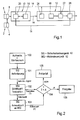
- FIG. 1 shows an electronic immobilizer for a vehicle, which has an ignition key 2 with built-in transponder 4, an ignition lock 6, an antenna 8, which can be arranged, for example, on the ignition lock 6, a safety control unit 10 and an engine control unit 12.
- a data line 14 connects the safety control unit 10 and the engine control unit 12.
- the antenna 8 is connected to the safety control unit 10.
- the safety controller 10 and the engine control unit 12 have memories 16, 18, in which a plurality of jointly known encryption algorithms are stored, and encryption devices 20, 22.
- the engine control unit has a random generator 24 and a comparator 26.
- the engine controller 12 and the safety controller 10 are preferably implemented using a microprocessor, but may also be implemented as part of existing control electronics.
- the safety controller 10 After an authentication or identification of the driver with respect to the safety control device 10 and after transmission of a driver's start request, which can be done for example by inserting the ignition key in the ignition and / or after switching on the vehicle voltage (step 100), the safety controller 10 sends a request signal for a random number to the engine control unit 12 (step 101).
- the engine control unit 12 After receipt of the request signal, the engine control unit 12 generates a random number via the random number generator 24 and sends this random number via the data line 14 in unencrypted form to the safety controller 10 (step 102).
- the security control unit 10 encrypts via the encryption device 20, the random number depending on the information to be transmitted or in dependence on the command to be transmitted with one of the memory 16 stored encryption algorithms, which is associated with the information or the command.
- the encryption algorithms are assigned to various vehicle-relevant functions of the engine control unit, for example a fuel supply, an ignition circuit, a starter circuit, etc.
- the encrypted random number is then sent back to the engine controller 12 as a response number (step 103), which supplies the response number to the comparator 26.
- the engine control unit encrypts the transmitted random number via the encryption device 22 with all the encryption algorithms stored in the memory 18 to form test numbers and supplies the encryption results or the test numbers to the comparator 26, which compares the test numbers with the encrypted response number of the security controller 10 (step 104) to determine the encryption algorithm used in matching the response number and the test number with which the security controller 10 has encrypted the random number.
- the encryption algorithms are chosen so that they always lead to different results, so that the engine control unit 12 can make a clear decision by the comparison.
- the engine controller 12 enables the vehicle-related function associated with the detected encryption algorithm so that the vehicle can be put into service (step 105). If not, the engine control unit remains locked and the corresponding function is not enabled (step 106). The vehicle can not be used then.
- the immobilizer may be configured to provide different encryption algorithms after each unlock operation or after a predetermined number of unlock operations.
- the immobilizer may be designed so that a release of a function only takes place when a match with several different test numbers of the engine control unit 12 has been determined for several different answer numbers of the safety control unit 10.
- the engine control unit can also be designed such that the engine control unit decrypts the response number received from the security control unit with the aid of all encryption algorithms and then decrypts the decrypted Compare results with the random number he sends. If there is a match between a decryption result and the random number sent, the procedure is analogous to that described above for comparing the test number and the number of responses.
- a chip card with transponder can also be used.
- An antenna and a transponder can be dispensed with when using, for example, a chip card or when using an ignition key with an EPROM whose chip or its EPROM can be electrically contacted for direct transmission of the characteristic data, so that the characteristic data can be read out directly from the safety control unit ,
- the characteristic data After transmission of the characteristic data, these can be deleted in the transponder, the chip or the EPROM. The information is then known only to the safety controller.
- the transponder 4 of any ignition key 2 or the transponder any key sets contain means for receiving and storing individual characteristics before installing the ignition key or the ignition key sets together with the ignition lock in a provided with the safety control unit and the engine control unit vehicle. By entering the characteristic data, the transponder is electronically individualized.
- the safety control unit 10 has means which, after installation of the ignition key sets / ignition key with ignition lock in the vehicle and intended commissioning of the vehicle, for example. By switching on the ignition, read the characteristics of the transponder 4, for example. Using the antenna , and store in a memory. The identifier read from the transponder is used to individualize the communication between the engine control unit and the safety control unit. The individualization between the transponder and the safety control device is realized by an identifier present in the safety control device.
- the data read from the transponder 4 and stored in a memory of the safety control unit 10 can be deleted after the storage in the transponder.
- the individual characteristics are then known only to the safety control unit 10.
- the individual characteristics may also be adopted by a tape end programmer, or they may also be specified by the safety controller itself, e.g. the characteristic data itself triggers.
- the advantage of the initialization provided for the immobilizer according to the invention during initial startup is that the identifier with which the safety controller and the engine control unit identify themselves, Ignition key and ignition lock are not known before starting to assemble.
- the ignition keys with identification are supplied together with the ignition lock. But it is unknown at this time in which vehicle the ignition lock is installed; This makes it possible to dispense with the individualization of the engine control unit and the safety control unit during production at the end of the tape.
- the risk of reading out the identifier before the ignition key has been learned is quite low. It can also be provided to teach only Optimizzünd negotiatel with existing individual identifier, so as to increase the security of the system.
- Blank ignition key for a vehicle manufacturer as they are used in the market so far, can be taught in any specialist workshop. This would not be possible with an ignition key with individual identifier.
- a chip card with transponder can also be used.
- An antenna can be dispensed with using, for example, a chip card whose chip can be contacted electronically or when using an ignition key with EPROM, which can be electrically contacted. As a result, the characteristics can be read directly from the safety control unit.
Landscapes
- Engineering & Computer Science (AREA)
- Mechanical Engineering (AREA)
- Lock And Its Accessories (AREA)
Claims (11)
- Dispositif antivol électronique pour véhicules, comportant un dispositif de commande de sécurité disposé dans le véhicule, un dispositif de commande de moteur pour les fonctions propres du véhicule, qui est relié au dispositif de commande de sécurité par l'intermédiaire d'une ligne signal, dans lequel des informations peuvent être échangées entre le dispositif de commande de sécurité et le dispositif de commande de moteur et le dispositif de commande de moteur ne peut fonctionner que lorsqu'il a obtenu un code d'autorisation d'accès légitimant l'utilisateur, comportant les caractéristiques suivantes .- le dispositif de commande de sécurité (10) et le dispositif de commande de moteur (12) possèdent des mémoires (16, 18), dans lesquelles plusieurs algorithmes de cryptage différents connus sont extraits respectivement, qui sont associés aux fonctions et/ou instructions/informations différents propres au véhicule,- le dispositif de commande de sécurité (10) envoie, après l'authentification ou l'identification du conducteur vis-à-vis du dispositif de commande de sécurité et après transmission du désir de démarrage de la part du conducteur, un signal de demande au dispositif de commande de moteur (12), qui présente un générateur d'accès (24) qui génère un nombre aléatoire à la réception du signal de demande,- le dispositif de commande de moteur (12) présente des moyens de transmission du nombre aléatoire au dispositif de commande de sécurité (10) par l'intermédiaire d'une ligne de données (14),- le dispositif de commande de sécurité (10) présente un dispositif de cryptage (20) qui sélectionne un algorithme de cryptage prédéterminé associé à l'information ou à l'instruction indépendamment de l'information à transmettre ou de l'ordre à transmettre à partir de l'algorithme de cryptage et crypte le nombre aléatoire envoyé avec cet algorithme de cryptage, et en outre un moyen, qui renvoie le nombre aléatoire en tant que nombre de réponse codé par l'intermédiaire de la ligne de données (14) au dispositif de commande de moteur (12), qui délivre le nombre de réponse à un comparateur (22),- le dispositif de commande de moteur (12) présente un dispositif de cryptage (22), qui crypte le nombre aléatoire envoyé avec tous les algorithmes de cryptage mémorisés dans la mémoire (18) pour la génération de nombres test et délivre les nombres tests au comparateur (22), qui compare les nombres tests au nombre de réponse du dispositif de commande de sécurité (10) et, lors de la constatation d'une correspondance entre le nombre test et le nombre de réponse, détecte l'algorithme de cryptage servant de base au nombre de réponse et au nombre test et génère l'information/ instruction associée à l'algorithme de cryptage et génère un signal de correspondance et lors d'une non correspondance entre le nombre test et le nombre de réponse génère un signal de non correspondance,- le dispositif de commande de moteur (12) présente un moyen relié au comparateur, qui déconnecte la fonction associée à l'algorithme de cryptage déterminé lors de la délivrance d'un signal de concordance.
- Dispositif antivol électronique selon la revendication 1, caractérisé en ce que le dispositif de commande de moteur décrypte le nombre de réponse reçu à l'aide de tous les algorithmes de cryptage et compare les résultats de décryptage au nombre aléatoire qu'il a envoyé au dispositif de commande de sécurité et, lors d'une concordance entre un résultat de décryptage et le nombre aléatoire envoyé, déconnecte la fonction propre au véhicule associée à l'algorithme de cryptage.
- Dispositif antivol selon la revendication 1 ou 2, caractérisé en ce que de nouveaux algorithmes de cryptage sont disponibles après l'exécution d'une déconnexion ou après un nombre déterminé de processus de déconnexion.
- Dispositif antivol selon la revendication 1 ou 2, caractérisé en ce qu'une déconnexion d'une fonction ne se produit que lorsqu'une concordance avec différents nombres tests ou résultats de décryptage du dispositif de commande de moteur (12) a été constatée pour plusieurs nombres de réponse différents du dispositif de commande de sécurité (10).
- Dispositif antivol selon la revendication 1, caractérisé par les caractéristiques suivantes pour une initialisation du dispositif antivol lors de la première mise en service du véhicule :- un dispositif (2, 4) pour la mise en service du véhicule contient un moyen (4) pour la mémorisation de données d'identification individuelles (code de déconnexion),- le dispositif de commande de sécurité (10) présente des moyens, qui, lors d'une mise en service intentionnelle du véhicule, extraient les données d'identification du dispositif (2, 4) et les mémorise dans une mémoire (16) du dispositif de commande de sécurité.
- Dispositif antivol selon la revendication 5, caractérisé en ce que les données d'identification sont effacées dans le dispositif (2, 4) après l'extraction et la mémorisation dans le dispositif de commande de sécurité.
- Dispositif antivol selon la revendication 5 ou 6, caractérisé en ce le dispositif est formé par une clé de contact quelconque (2) comportant des transpondeurs (4) ou par des jeux de clé de contact comportant des transpondeurs, dans lequel les transpondeurs présentent des moyens pour la mémorisation des données d'identification individuelles (codes de déconnexion) avant l'insertion de la serrure de contact ou des jeux de clé de contact conjointement avec la serrure de contact (6) dans un véhicule équipé d'un dispositif de commande de sécurité (10) et d'un dispositif de commande de moteur (12) et en ce que le dispositif de commande de sécurité (10) présente des moyens, qui extraient les données d'identification du transpondeur (4) après l'insertion de la clé de contact ou des clés de contact (2) avec la serrure de contact dans le véhicule, lors d'une mise en service intentionnelle, par exemple lors de l'activation de l'allumage, et les mémorisent dans la mémoire (16) du dispositif de commande de sécurité.
- Dispositif antivol selon la revendication 5, caractérisé en ce que les clés de contact supplémentaires sont prévues avec une identification individuelle pour le processus d'apprentissage.
- Dispositif antivol selon l'une des revendications 5 à 8, caractérisé en ce que le dispositif est une carte à puce avec un transpondeur ou une carte à puce avec une puce par contact électronique pour une extraction directe ou une clé de contact avec une EPROM à contact électronique.
- Dispositif antivol selon l'une des revendications 5 à 9, caractérisé en ce que les données d'identification individuelles sont extraites par un programmateur fin de bande.
- Dispositif antivol selon l'une des revendications 5 à 9, caractérisé en ce que les données d'identification individuelles sont définies par le dispositif de commande de sécurité par déclenchement automatique.
Applications Claiming Priority (1)
| Application Number | Priority Date | Filing Date | Title |
|---|---|---|---|
| DE102004035033A DE102004035033A1 (de) | 2004-07-20 | 2004-07-20 | Elektronische Wegfahrsperre |
Publications (2)
| Publication Number | Publication Date |
|---|---|
| EP1619094A1 EP1619094A1 (fr) | 2006-01-25 |
| EP1619094B1 true EP1619094B1 (fr) | 2007-04-04 |
Family
ID=35004265
Family Applications (1)
| Application Number | Title | Priority Date | Filing Date |
|---|---|---|---|
| EP05012939A Active EP1619094B1 (fr) | 2004-07-20 | 2005-06-16 | Dispositif anti-vol éléctronique |
Country Status (2)
| Country | Link |
|---|---|
| EP (1) | EP1619094B1 (fr) |
| DE (2) | DE102004035033A1 (fr) |
Families Citing this family (4)
| Publication number | Priority date | Publication date | Assignee | Title |
|---|---|---|---|---|
| EP1731390B1 (fr) * | 2005-06-09 | 2010-01-06 | Mazda Motor Corporation | Un système et méthode passif d'entrée sans clef de véhicule |
| DE102007005150B3 (de) * | 2007-02-01 | 2008-07-10 | Siemens Ag | Rechneranordnung für ein Kraftfahrzeug |
| JP4842907B2 (ja) * | 2007-10-04 | 2011-12-21 | 本田技研工業株式会社 | イモビライザ装置 |
| DE102008019195A1 (de) | 2008-04-17 | 2009-10-29 | Beckhoff Automation Gmbh | Verfahren zum Betreiben einer Sicherheitssteuerung und Automatisierungsnetzwerk mit einer solchen Sicherheitssteuerung |
Family Cites Families (11)
| Publication number | Priority date | Publication date | Assignee | Title |
|---|---|---|---|---|
| DE4201568C2 (de) | 1992-01-22 | 1995-12-21 | Vdo Schindling | Verfahren zur Synchronisation von Sender und Empfänger |
| DE4240831C1 (de) * | 1992-12-04 | 1993-10-07 | Braun Melsungen Ag | Nahtmaterialpackung |
| DE4411451C1 (de) * | 1994-04-01 | 1995-05-04 | Daimler Benz Ag | Fahrzeugsicherungseinrichtung mit elektronischer Nutzungsberechtigungscodierung |
| DE19520505A1 (de) * | 1995-06-03 | 1996-12-05 | Bosch Gmbh Robert | Wegfahrsperre |
| DE19526530C1 (de) * | 1995-07-20 | 1996-08-14 | Siemens Ag | Verfahren zum Initialisieren einer Wegfahrsperre und Wegfahrsperre |
| DE19637657A1 (de) * | 1996-09-16 | 1998-03-19 | Bosch Gmbh Robert | Fahrzeugsicherungsanordnung |
| DE19652256A1 (de) * | 1996-12-16 | 1998-06-18 | Bosch Gmbh Robert | Verfahren zur Sicherung der Datenübertragung |
| DE19721286C1 (de) * | 1997-05-21 | 1998-09-17 | Siemens Ag | Verfahren zum Initialisieren eines Diebstahlschutzsystems eines Kraftfahrzeugs |
| DE19960958B4 (de) * | 1999-12-17 | 2004-10-07 | Robert Bosch Gmbh | Vorrichtung zum Diebstahlschutz |
| DE10020977A1 (de) * | 2000-04-28 | 2001-10-31 | Witte Velbert Gmbh & Co Kg | Elektronische Steuereinrichtung an einem Kraftfahrzeug |
| DE10052244A1 (de) * | 2000-10-21 | 2002-05-16 | Hella Kg Hueck & Co | Vorrichtung und Verfahren zur Diebstahlsicherung von Kraftfahrzeugelektronikkomponenten |
-
2004
- 2004-07-20 DE DE102004035033A patent/DE102004035033A1/de not_active Withdrawn
-
2005
- 2005-06-16 DE DE502005000546T patent/DE502005000546D1/de active Active
- 2005-06-16 EP EP05012939A patent/EP1619094B1/fr active Active
Also Published As
| Publication number | Publication date |
|---|---|
| DE502005000546D1 (de) | 2007-05-16 |
| DE102004035033A1 (de) | 2006-02-16 |
| EP1619094A1 (fr) | 2006-01-25 |
Similar Documents
| Publication | Publication Date | Title |
|---|---|---|
| DE102006011685B4 (de) | Sicherheitssystem mit gegenseitiger Berechtigungsüberprüfung mit Wiederherstellung aus einer teilweisen Programmierung | |
| EP1999725B1 (fr) | Procédé de protection d'un bien mobile, notamment d'un véhicule, contre toute utilisation non autorisée | |
| DE19532067C1 (de) | Verfahren und Einrichtung zur Einprogrammierung von Betriebsdaten in Fahrzeugbauteile | |
| DE102006013504B4 (de) | Technik zum Programmieren eines geheimen Schlüssels für einen Transponder unter Verwendung einer Verschlüsselung | |
| EP0723896B1 (fr) | Procédé de protection anti-vol pour véhicules à moteur | |
| DE102018123656A1 (de) | Zusatzmodul und system für die gemeinsame nutzung von fahrzeugen | |
| DE112007001608T5 (de) | Kontrolle von Flottenfahrzeugen mit üblichen Transmittern | |
| DE102007022100B4 (de) | Kraftfahrzeugsteuergerätedatenübertragungssystem und -verfahren | |
| EP3649625B1 (fr) | Procédé de délégation de droits d'accès | |
| EP0925209B1 (fr) | Dispositif servant a empecher le vol d'un vehicule | |
| EP1619094B1 (fr) | Dispositif anti-vol éléctronique | |
| DE19501004C2 (de) | Verfahren zur verifizierbaren Datenübertragung zwischen einem Transponder und einem Lesegerät | |
| WO2021023465A1 (fr) | Système de fermeture, en particulier pour un véhicule | |
| DE4433499C2 (de) | Elektronisches Diebstahlschutzsystem für ein Kraftfahrzeug | |
| DE10112573C2 (de) | Verfahren zum Initialisieren eines Diebstahlschutzsystems für ein Kraftfahrzeug | |
| DE69817889T2 (de) | Sicherheitsvorrichtung für Kraftfahrzeuge und Lernverfahren dafür | |
| EP1108631A2 (fr) | Dispositif de protection antivol | |
| EP1038080B1 (fr) | Systeme de controle d'autorisation d'acces | |
| EP0879160B2 (fr) | Dispositif antivol pour automobiles et procede antivol | |
| DE102007005068B3 (de) | Diebstahlsicherungssystem | |
| DE102018204842A1 (de) | Verfahren zum Betreiben eines Kraftfahrzeugs, Authentifizierungseinrichtung, Speichermedium, Kraftfahrzeug, mobiles portables Endgerät, Datenservereinrichtung zum Betreiben im Internet | |
| DE10337424B4 (de) | Verfahren zur Sicherung eines Fahrzeuges gegen Diebstahl | |
| EP0683293A1 (fr) | Procédé d'exploitation d'un système de transmission de données composé d'un transpondeur et d'un dispositif de lecture | |
| DE102007031738A1 (de) | Verfahren und System zur Sicherung der Datenübertragung zwischen mindestens zwei Bordelektronikkomponenten eines Kraftfahrzeugs | |
| EP1967423A2 (fr) | Procédé et dispositif pour la transmission de données et la réalisation des actions associées avec les données |
Legal Events
| Date | Code | Title | Description |
|---|---|---|---|
| PUAI | Public reference made under article 153(3) epc to a published international application that has entered the european phase |
Free format text: ORIGINAL CODE: 0009012 |
|
| AK | Designated contracting states |
Kind code of ref document: A1 Designated state(s): AT BE BG CH CY CZ DE DK EE ES FI FR GB GR HU IE IS IT LI LT LU MC NL PL PT RO SE SI SK TR |
|
| AX | Request for extension of the european patent |
Extension state: AL BA HR LV MK YU |
|
| 17P | Request for examination filed |
Effective date: 20060725 |
|
| AKX | Designation fees paid |
Designated state(s): DE FR IT NL SE |
|
| GRAP | Despatch of communication of intention to grant a patent |
Free format text: ORIGINAL CODE: EPIDOSNIGR1 |
|
| RAP1 | Party data changed (applicant data changed or rights of an application transferred) |
Owner name: WABCO GMBH |
|
| GRAS | Grant fee paid |
Free format text: ORIGINAL CODE: EPIDOSNIGR3 |
|
| GRAA | (expected) grant |
Free format text: ORIGINAL CODE: 0009210 |
|
| AK | Designated contracting states |
Kind code of ref document: B1 Designated state(s): DE FR IT NL SE |
|
| REF | Corresponds to: |
Ref document number: 502005000546 Country of ref document: DE Date of ref document: 20070516 Kind code of ref document: P |
|
| REG | Reference to a national code |
Ref country code: SE Ref legal event code: TRGR |
|
| ET | Fr: translation filed | ||
| PLBE | No opposition filed within time limit |
Free format text: ORIGINAL CODE: 0009261 |
|
| STAA | Information on the status of an ep patent application or granted ep patent |
Free format text: STATUS: NO OPPOSITION FILED WITHIN TIME LIMIT |
|
| 26N | No opposition filed |
Effective date: 20080107 |
|
| EUG | Se: european patent has lapsed | ||
| PG25 | Lapsed in a contracting state [announced via postgrant information from national office to epo] |
Ref country code: SE Free format text: LAPSE BECAUSE OF NON-PAYMENT OF DUE FEES Effective date: 20100617 |
|
| REG | Reference to a national code |
Ref country code: DE Ref legal event code: R081 Ref document number: 502005000546 Country of ref document: DE Owner name: WABCO EUROPE BVBA, BE Free format text: FORMER OWNER: WABCO GMBH, 30453 HANNOVER, DE Effective date: 20121214 |
|
| REG | Reference to a national code |
Ref country code: FR Ref legal event code: TP Owner name: WABCO EUROPE BVBA, BE Effective date: 20130717 |
|
| REG | Reference to a national code |
Ref country code: NL Ref legal event code: SD Effective date: 20150114 |
|
| REG | Reference to a national code |
Ref country code: FR Ref legal event code: PLFP Year of fee payment: 12 |
|
| REG | Reference to a national code |
Ref country code: FR Ref legal event code: PLFP Year of fee payment: 13 |
|
| REG | Reference to a national code |
Ref country code: FR Ref legal event code: PLFP Year of fee payment: 14 |
|
| REG | Reference to a national code |
Ref country code: DE Ref legal event code: R081 Ref document number: 502005000546 Country of ref document: DE Owner name: ZF CV SYSTEMS EUROPE BV, BE Free format text: FORMER OWNER: WABCO EUROPE BVBA, BRUXELLES, BE |
|
| P01 | Opt-out of the competence of the unified patent court (upc) registered |
Effective date: 20230528 |
|
| PGFP | Annual fee paid to national office [announced via postgrant information from national office to epo] |
Ref country code: NL Payment date: 20230620 Year of fee payment: 19 Ref country code: FR Payment date: 20230620 Year of fee payment: 19 Ref country code: DE Payment date: 20230630 Year of fee payment: 19 |
|
| PGFP | Annual fee paid to national office [announced via postgrant information from national office to epo] |
Ref country code: SE Payment date: 20230622 Year of fee payment: 19 |
|
| PGFP | Annual fee paid to national office [announced via postgrant information from national office to epo] |
Ref country code: IT Payment date: 20230630 Year of fee payment: 19 |