EP1618850A2 - Système de commande et procédé d'application d'energie aux parois aeriennes du poumon et à d'autres milieux - Google Patents
Système de commande et procédé d'application d'energie aux parois aeriennes du poumon et à d'autres milieux Download PDFInfo
- Publication number
- EP1618850A2 EP1618850A2 EP05019417A EP05019417A EP1618850A2 EP 1618850 A2 EP1618850 A2 EP 1618850A2 EP 05019417 A EP05019417 A EP 05019417A EP 05019417 A EP05019417 A EP 05019417A EP 1618850 A2 EP1618850 A2 EP 1618850A2
- Authority
- EP
- European Patent Office
- Prior art keywords
- energy
- controller
- temperature
- seconds
- energy delivery
- Prior art date
- Legal status (The legal status is an assumption and is not a legal conclusion. Google has not performed a legal analysis and makes no representation as to the accuracy of the status listed.)
- Withdrawn
Links
Images


Classifications
-
- A—HUMAN NECESSITIES
- A61—MEDICAL OR VETERINARY SCIENCE; HYGIENE
- A61B—DIAGNOSIS; SURGERY; IDENTIFICATION
- A61B18/00—Surgical instruments, devices or methods for transferring non-mechanical forms of energy to or from the body
- A61B18/04—Surgical instruments, devices or methods for transferring non-mechanical forms of energy to or from the body by heating
- A61B18/08—Surgical instruments, devices or methods for transferring non-mechanical forms of energy to or from the body by heating by means of electrically-heated probes
-
- A—HUMAN NECESSITIES
- A61—MEDICAL OR VETERINARY SCIENCE; HYGIENE
- A61B—DIAGNOSIS; SURGERY; IDENTIFICATION
- A61B18/00—Surgical instruments, devices or methods for transferring non-mechanical forms of energy to or from the body
- A61B18/04—Surgical instruments, devices or methods for transferring non-mechanical forms of energy to or from the body by heating
- A61B18/12—Surgical instruments, devices or methods for transferring non-mechanical forms of energy to or from the body by heating by passing a current through the tissue to be heated, e.g. high-frequency current
- A61B18/1206—Generators therefor
-
- A—HUMAN NECESSITIES
- A61—MEDICAL OR VETERINARY SCIENCE; HYGIENE
- A61B—DIAGNOSIS; SURGERY; IDENTIFICATION
- A61B18/00—Surgical instruments, devices or methods for transferring non-mechanical forms of energy to or from the body
- A61B18/04—Surgical instruments, devices or methods for transferring non-mechanical forms of energy to or from the body by heating
- A61B18/12—Surgical instruments, devices or methods for transferring non-mechanical forms of energy to or from the body by heating by passing a current through the tissue to be heated, e.g. high-frequency current
- A61B18/14—Probes or electrodes therefor
- A61B18/1477—Needle-like probes
-
- A—HUMAN NECESSITIES
- A61—MEDICAL OR VETERINARY SCIENCE; HYGIENE
- A61B—DIAGNOSIS; SURGERY; IDENTIFICATION
- A61B18/00—Surgical instruments, devices or methods for transferring non-mechanical forms of energy to or from the body
- A61B18/04—Surgical instruments, devices or methods for transferring non-mechanical forms of energy to or from the body by heating
- A61B18/12—Surgical instruments, devices or methods for transferring non-mechanical forms of energy to or from the body by heating by passing a current through the tissue to be heated, e.g. high-frequency current
- A61B18/14—Probes or electrodes therefor
- A61B18/1492—Probes or electrodes therefor having a flexible, catheter-like structure, e.g. for heart ablation
-
- A—HUMAN NECESSITIES
- A61—MEDICAL OR VETERINARY SCIENCE; HYGIENE
- A61B—DIAGNOSIS; SURGERY; IDENTIFICATION
- A61B18/00—Surgical instruments, devices or methods for transferring non-mechanical forms of energy to or from the body
- A61B18/18—Surgical instruments, devices or methods for transferring non-mechanical forms of energy to or from the body by applying electromagnetic radiation, e.g. microwaves
- A61B18/1815—Surgical instruments, devices or methods for transferring non-mechanical forms of energy to or from the body by applying electromagnetic radiation, e.g. microwaves using microwaves
-
- A—HUMAN NECESSITIES
- A61—MEDICAL OR VETERINARY SCIENCE; HYGIENE
- A61B—DIAGNOSIS; SURGERY; IDENTIFICATION
- A61B18/00—Surgical instruments, devices or methods for transferring non-mechanical forms of energy to or from the body
- A61B2018/00053—Mechanical features of the instrument of device
- A61B2018/00059—Material properties
- A61B2018/00071—Electrical conductivity
- A61B2018/00083—Electrical conductivity low, i.e. electrically insulating
-
- A—HUMAN NECESSITIES
- A61—MEDICAL OR VETERINARY SCIENCE; HYGIENE
- A61B—DIAGNOSIS; SURGERY; IDENTIFICATION
- A61B18/00—Surgical instruments, devices or methods for transferring non-mechanical forms of energy to or from the body
- A61B2018/00053—Mechanical features of the instrument of device
- A61B2018/00214—Expandable means emitting energy, e.g. by elements carried thereon
- A61B2018/00267—Expandable means emitting energy, e.g. by elements carried thereon having a basket shaped structure
-
- A—HUMAN NECESSITIES
- A61—MEDICAL OR VETERINARY SCIENCE; HYGIENE
- A61B—DIAGNOSIS; SURGERY; IDENTIFICATION
- A61B18/00—Surgical instruments, devices or methods for transferring non-mechanical forms of energy to or from the body
- A61B2018/00315—Surgical instruments, devices or methods for transferring non-mechanical forms of energy to or from the body for treatment of particular body parts
- A61B2018/00541—Lung or bronchi
-
- A—HUMAN NECESSITIES
- A61—MEDICAL OR VETERINARY SCIENCE; HYGIENE
- A61B—DIAGNOSIS; SURGERY; IDENTIFICATION
- A61B18/00—Surgical instruments, devices or methods for transferring non-mechanical forms of energy to or from the body
- A61B2018/00636—Sensing and controlling the application of energy
- A61B2018/00666—Sensing and controlling the application of energy using a threshold value
- A61B2018/00678—Sensing and controlling the application of energy using a threshold value upper
-
- A—HUMAN NECESSITIES
- A61—MEDICAL OR VETERINARY SCIENCE; HYGIENE
- A61B—DIAGNOSIS; SURGERY; IDENTIFICATION
- A61B18/00—Surgical instruments, devices or methods for transferring non-mechanical forms of energy to or from the body
- A61B2018/00636—Sensing and controlling the application of energy
- A61B2018/00773—Sensed parameters
- A61B2018/00791—Temperature
- A61B2018/00803—Temperature with temperature prediction
-
- A—HUMAN NECESSITIES
- A61—MEDICAL OR VETERINARY SCIENCE; HYGIENE
- A61B—DIAGNOSIS; SURGERY; IDENTIFICATION
- A61B18/00—Surgical instruments, devices or methods for transferring non-mechanical forms of energy to or from the body
- A61B2018/00636—Sensing and controlling the application of energy
- A61B2018/00773—Sensed parameters
- A61B2018/00791—Temperature
- A61B2018/00821—Temperature measured by a thermocouple
-
- A—HUMAN NECESSITIES
- A61—MEDICAL OR VETERINARY SCIENCE; HYGIENE
- A61B—DIAGNOSIS; SURGERY; IDENTIFICATION
- A61B18/00—Surgical instruments, devices or methods for transferring non-mechanical forms of energy to or from the body
- A61B2018/00636—Sensing and controlling the application of energy
- A61B2018/00898—Alarms or notifications created in response to an abnormal condition
-
- A—HUMAN NECESSITIES
- A61—MEDICAL OR VETERINARY SCIENCE; HYGIENE
- A61B—DIAGNOSIS; SURGERY; IDENTIFICATION
- A61B18/00—Surgical instruments, devices or methods for transferring non-mechanical forms of energy to or from the body
- A61B18/04—Surgical instruments, devices or methods for transferring non-mechanical forms of energy to or from the body by heating
- A61B18/12—Surgical instruments, devices or methods for transferring non-mechanical forms of energy to or from the body by heating by passing a current through the tissue to be heated, e.g. high-frequency current
- A61B18/14—Probes or electrodes therefor
- A61B2018/1405—Electrodes having a specific shape
- A61B2018/1417—Ball
Definitions
- This invention is related to systems for applying energy to lung airways and in particular, to a system and method for controlling the energy delivered to the airways using a PID algorithm to minimize error between a preset temperature and a measured temperature.
- Asthma a disease in which bronchoconstriction, excessive mucus production, and inflammation and swelling of airways occur, causing widespread but variable airflow obstruction thereby making it difficult for the asthma sufferer to breathe.
- Asthma is a chronic disorder, primarily characterized by persistent airway inflammation. Asthma is further characterized by acute episodes of additional airway narrowing via contraction of hyper-responsive airway smooth muscle.
- Reversible aspects of obstructive pulmonary disease generally include excessive mucus production in the bronchial tree. Usually, there is a general increase in bulk (hypertrophy) of the large bronchi and chronic inflammatory changes in the small airways. Excessive amounts of mucus are found in the airways and semisolid plugs of mucus may occlude some small bronchi. Also, the small airways are narrowed and show inflammatory changes. Reversible aspects include partial airway occlusion by excess secretions and airway narrowing secondary to smooth muscle contraction, bronchial wall edema and inflammation of the airways.
- asthma can also lead to remodeling of the airway wall (i.e., structural changes such as thickening or edema) which can further affect the function of the airway wall and influence airway hyper-responsiveness.
- Other physiologic changes associated with asthma include excess mucus production, and if the asthma is severe, mucus plugging, as well as ongoing epithelial denudation and repair.
- Epithelial denudation exposes the underlying tissue to substances that would not normally come in contact with them, further reinforcing the cycle of cellular damage and inflammatory response.
- asthma symptoms include recurrent episodes of shortness of breath (dyspnea), wheezing, chest tightness, and cough.
- dyspnea shortness of breath
- wheezing wheezing
- chest tightness chest tightness
- cough Currently, asthma is managed by a combination of stimulus avoidance and pharmacology.
- Stimulus avoidance is accomplished via systematic identification and minimization of contact with each type of stimuli. It may, however, be impractical and not always helpful to avoid all potential stimuli.
- Pharmacological management of asthma includes: (1) long term control through use of anti-inflammatories and long-acting bronchodilators and (2) short term management of acute exacerbations through use of short-acting bronchodilators. Both of these approaches require repeated and regular use of the prescribed drugs. High doses of corticosteroid antiinflammatory drugs can have serious side effects that require careful management. In addition, some patients are resistant to steroid treatment. The difficulty involved in patient compliance with pharmacologic management and the difficulty of avoiding stimulus that triggers asthma are common barriers to successful asthma management. Current management techniques are thus neither completely successful nor free from side effects. Accordingly, it would be desirable to provide a system and method which improves airflow without the need for patient compliance.
- Variations in lung tissue structure occur for a number of reasons such as: the branching pattern of the tracheobronchial tree leads to local variation in the size and presence of airways; the vasculature of the lungs is a similar distributed network causing variation in size and presence of blood vessels; within the airways are variable amounts of differing structures such as cartilage, airway smooth muscle, and mucus glands and ducts; and energy delivery may also be influenced differently at the periphery, near the outer surface of a lung lobe, than in the central portion.
- Lung airways also include a number of protruding folds.
- Other tissue structures such as blood vessels typically do not have the folds found in airways.
- Airways contain mucous and air whereas other structures contain different substances.
- the tissue chemistry between various lumens and airways is also different. In view of these differences, it is not surprising that conventional energy delivering systems cannot be universally applied to treat all tissue structures. Moreover, power shut-offs and other safety mechanisms must be precisely tailored to specific tissue so that the tissue is not harmed by application of excess energy.
- an intraluminal RF energy delivering system that is capable of safely delivering RF energy to lung airways is desired.
- a system which is capable of controlling the temperature when treating an airway of an asthma or COPD patient is desired. It is also desirable to provide a system having built-in safeguards that shut the power off thereby preventing damage to the subject tissue or collateral tissue.
- the present invention includes a system for delivering energy to an airway wall of a lung comprising an energy delivering apparatus and a PID controller.
- the energy delivering apparatus may include a flexible elongated member and a distal expandable basket having at least one electrode for transferring energy to the airway wall and at least one temperature sensor for measuring temperature (T M ) of the airway wall when energy is delivered to the airway wall.
- the system further comprises a PID controller for determining a new power set point (P i+1 ) based on an error (e) between a preset temperature (T S ) and the measured temperature wherein the PID controller applies an algorithm having a variable gain factor (G).
- the gain factor used in the PID algorithm is reset 0.1 to 2 seconds after energy delivery has begun.
- the gain factor can also be reset 0.5 seconds after energy delivery has begun.
- the invention includes resetting G to 0.9 to 1.0 if a temperature rise in °C per Joule is less than or equal to 2.5; 0.4 to 0.5 if a temperature rise in °C per Joule is between 2.5 to 5.0; to 0.2 to 0.3 if a temperature rise in °C per Joule is equal to 5.0 to 7.5; and to 0.1 to 0.2 if a temperature rise in °C per Joule is greater than 7.5.
- the gain factor is equal to 0.4 to 0.5 and preferably 0.45 to 0.47.
- the invention includes configuring the controller such that G 1 ,G 2 and G 3 are reset to 0.9 to 2.00, -0.9 to -2.00 and 0.5 to -0.5 respectively if a temperature rise in °C per Joule is less than or equal to 2.5; to 0.40 to 1.00, -0.40 to -1.00 and 0.25 to -0.25 respectively if a temperature rise in °C per Joule is between 2.5 to 5.0; to 0.20 to 0.60, -0.20 to -0.60 and 0.15 to -0.15 respectively if a temperature rise in °C per Joule is equal to 5.0 to 7.5; and to 0.10 to 0.40, -0.10 to -0.40 and 0.10 to -0.10 respectively if a temperature rise in °C
- the controller is configured such that the energy delivery is terminated if the energy delivered exceeds a maximum energy such as 120 joules.
- the controller is configured to deliver energy for an activation time period such as up to 15 seconds, 8 to 12 seconds, or 10 seconds.
- the controller is configured such that T S is set at a value between 60 to 80 ° C, or 65 ° C.
- the controller is configured to measure impedance and said energy delivery is terminated when said impedance drops below a preset impedance value such as 40 to 60 ohms.
- the controller is configured to terminate the energy delivery if T M exceeds T S by a pre-selected value such as 10, 15 or 20 °C.
- the controller is configured to terminate the energy delivery if the output power is greater or equal to a nominal output power and T M drops by a critical temperature difference within a sampling period.
- the invention includes a nominal output power set at a value of at least 17 watts; the sampling period is set at a value of at least 0.5 seconds; and the critical temperature difference is 2 ° C.
- the controller is configured to terminate the energy delivery if said T M averaged over a time window exceeds T S by a fixed temperature difference.
- the fixed temperature difference may be a value between 1 and 10 ° C or 5 ° C.
- the time window is between 1 and 5 seconds or 2 seconds.
- the controller is configured to terminate if the measured temperature drops by 10 or more °C in a sample period such as 1.0 seconds or 0.2 seconds.
- Another variation of the present invention is a method for treating a lung by transferring energy from an active region of an energy delivery apparatus to an airway wall of the lung.
- the energy delivery apparatus includes a flexible elongate body and a distal section and the active region is located in the distal section.
- the energy delivery apparatus further has a temperature sensor located in the distal section for measuring a temperature (T M ) of said airway wall and the method comprises the following steps: setting a preset temperature (T S ); determining a power set point (P i ) to deliver energy from the active region to the target medium; measuring the T M using the temperature sensor; and determining a new power set point (P i+1 ) based on an error (e) between the preset temperature (T S ) and the measured temperature (T M ) using a PID algorithm.
- T S preset temperature
- P i power set point
- a process for transferring energy to a target medium using an energy delivery apparatus includes a flexible elongate body and a distal section wherein the distal section includes an expandable basket with at least one active region for transferring energy to the target medium.
- the energy delivery apparatus further has a temperature sensor located in the distal section for measuring a temperature (T M ) of the target medium.
- the process comprises the following steps: setting a preset temperature (T S ); determining a power set point (P i ) to deliver energy from the active region to the target medium; measuring T M using the temperature sensor; and determining a new power set point (P i+1 ) based on an error (e) between the preset temperature (T S ) and the measured temperature (T M ) using an algorithm having a variable gain factor.
- the energy may be delivered to an airway wall of a lung in vivo, in vitro or to another target such as a sponge or towel which may be moistened with saline solution. Saline solution increases the conductivity of the target.
- the gain factor is reset 0.1 to 2 seconds after energy delivery has begun.
- the gain factor can also be reset 0.5 seconds after energy delivery has begun.
- the invention includes resetting G to 0.9 to 1.0 if a temperature rise in °C per Joule is less than or equal to 2.5; 0.4 to 0.5 if a temperature rise in °C per Joule is between 2.5 to 5.0; to 0.2 to 0.3 if a temperature rise in °C per Joule is equal to 5.0 to 7.5; and to 0.1 to 0.2 if a temperature rise in °C per Joule is greater than 7.5.
- the gain factor is equal to 0.4 to 0.5 and preferably 0.45 to 0.47.
- the energy delivery is terminated if the energy delivered exceeds a maximum energy such as 120 joules.
- energy is delivered for an activation time period such as 0 to 15 seconds, 8 to 12 seconds, or 10 seconds.
- T S is set at a value between 60 to 80, or 65 ° C.
- impedance is measured and energy delivery is terminated when the impedance drops below a preset impedance value such as 40 to 60 ohms.
- the energy is terminated if T M exceeds T S by a pre-selected value such as 10, 15 or 20 ° C.
- energy is terminated if the output power is greater or equal to a nominal output power and T M drops by a critical temperature difference within a sampling period.
- the nominal output power is set at a value of at least 17 watts; the sampling period is set at a value of at least 0.5 seconds; and the critical temperature difference is 2°C.
- the energy delivery apparatus is configured to deliver an amount of power up to a maximum power.
- the maximum power can be from 10 to 40 watts and preferably from 15 to 20 watts.
- energy delivery is terminated if T M averaged over a time window exceeds T S by a fixed temperature difference.
- the fixed temperature difference may be a value between 1 and 10 ° C or 5 ° C.
- the time window is between 1 and 5 seconds or 2 seconds.
- the energy delivery is terminated if the measured temperature drops by 10 or more ° C in a sample period such as 1.0 seconds or 0.2 seconds.
- the present invention includes a controller and an energy deliver apparatus to deliver energy to the airway walls of the lungs.
- the controller includes a feedback loop having a variable gain factor as diagramed in FIG. 1.
- the system is useful in treating asthma and various symptoms of reversible obstructive pulmonary disease. Examples of suitable applications and methods are disclosed in International Application No. PCT/US00/28745 filed October 17, 2000.
- FIG. 2A and 2B a cross section of two different airways in a healthy patient is shown.
- the airway of FIG. 2A is a medium sized bronchus having an airway diameter D1 of about 3 mm.
- FIG. 2B shows a section through a bronchiole having an airway diameter D2 of about 1.5 mm.
- Each airway includes a folded inner surface or epithelium 10 surrounded by stroma 12 and smooth muscle tissue 14.
- the larger airways including the bronchus shown in FIG. 2A also have mucous glands 16 and cartilage 18 surrounding the smooth muscle tissue 14. Nerve fibers 20 and blood vessels 24 surround the airway.
- FIG. 3 illustrates the bronchus of FIG. 2A in which the smooth muscle 14 has hypertrophied and increased in thickness causing the airway diameter to be reduced from the diameter D1 to a diameter D3.
- the airways to be treated with the device of the present invention may be 1 mm in diameter or greater, more preferably 3 mm in diameter or greater.
- FIG. 4 is an illustration of the lungs being treated with a system 36 according to the present invention.
- the system 36 includes a controller 32 and an energy treatment device 30 which may be an elongated member as described further below.
- the device 30 also includes an expandable distal section which can be positioned at a treatment site 34 within a lung or another target medium. In operation, the device is manipulated to the treatment site 34.
- RF energy for example, is delivered through the energy delivering device and penetrates the surface of the lung tissue such that tissue is affected below the epithelial layer as well as on the surface of the lung tissue.
- the present invention includes a controller 32 and a device 30 through which it delivers energy to the target medium 34.
- a device 30 of the present invention should be of a size to access the bronchus or bronchioles of the human lung.
- the device may be sized to fit within bronchoscopes, preferably, with bronchoscopes having a working channel of 2 mm or less.
- the device may also include a steering member configured to guide the device to a desired target location. For example, this steering member may deflect a distal tip of the device in a desired direction to navigate to a desired bronchi or bronchiole.
- the energy delivering apparatus 30 typically includes an elongate body having a proximal section and a distal section.
- the distal section features a radially expandable basket having a plurality of legs.
- the legs may be electrodes or have an active region defined by an insulated covering which contacts the medium to be treated.
- the basket is expanded with an actuator mechanism which may be provided in a handle attached to proximal end of the elongate body. Examples of energy delivering devices in accordance with the present invention are described in co-pending U.S. Application No. 09/436,455 filed November 8, 1999 which is hereby incorporated by reference in its entirety.
- the invention also includes a temperature detecting element.
- temperature detecting elements include thermocouples, infrared sensors, thermistors, resistance temperature detectors (RTDs), or any other apparatus capable of detecting temperatures or changes in temperature.
- the temperature detecting element is preferably placed in proximity to the expandable member.
- FIG. 5A is a partial view of a variation of the invention having thermocouple 137 positioned about midway along basket leg 106.
- FIG. 5B is an enlarged partial view of the thermocouple 137 of FIG. 5A showing the leads 139 separately coupled on an inwardly-facing surface of the leg 106. Consequently, the basket leg itself is used as part of the thermocouple junction upon which the temperature measurement is based. In other words, the thermocouple junction is intrinsic to the basket leg. This configuration is preferred because it provides an accurate temperature measurement of tissue contacting the leg 106 in the vicinity of the thermocouple leads.
- typical thermocouple configurations consist of a thermocouple junction offset or extrinsic to the basket leg. We believe that thermocouple junctions having an offset from or extrinsic to the basket leg do not measure temperature as accurately in certain applications as thermocouple junctions which are intrinsic to the basket leg.
- the leads 139 may be placed at other locations along the leg 106 including an edge 405. Joining the leads 139 to the edge 405, however, is undesirable because of its relatively small bonding surface.
- FIG. 5B also shows basket leg 106 having an outer insulating material or coating 410.
- the boundaries 415 of the insulating material 410 define an uninsulated, active section of electrode leg 106 which delivers energy to the tissue walls.
- the insulating coating 410 is heat shrink tubing or a polymeric coating. However, other insulating materials may be used.
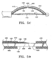
- FIGS. 5C and 5D show another variation of the present invention having thin foil or laminated thermocouple leads 139.
- the thermocouple leads 139 are configured as foils or layers which can be, for example, prefabricated foils or sputtered films. Suitable materials for the thermocouple leads (listed in pairs) include, but are not limited to: Constantan and Copper; Constantan and Nickel-Chromium; Constantan and Iron; and Nickel-Aluminum and Nickel-Chromium.
- the thermocouple pair, CHROMEL and ALUMEL (both of which are registered trademarks of Hoskins Manufacturing) is preferred. CHROMEL and ALUMEL is a standard thermocouple pair and has been shown to be biocompatible and corrosion resistant in our applications.
- thermocouple leads 139 may be placed such that each lead approaches the center of the basket leg from an opposite end of the basket leg. The leads 139 then terminate in bond joints 440 and 450. Alternatively, as shown in the configuration of FIG. 5D, both thermocouple leads 139 may run from the same end of the basket leg 106.
- insulating layers 430 and 440 are disposed between the thin film leads 139 and the basket leg 106.
- the insulating layers 430 and 440 electrically separate the leads 139 as well as electrically separate the leads from the leg 106.
- the insulating layers 430 and 440 limit the thermocouple junction to bond joints 450 and 460, which are optimally positioned on active region 420 of basket leg 106.
- the present invention includes a controller which controls the energy to be delivered to the airways via an energy transfer device.
- the controller includes at least one of the novel features disclosed hereinafter and may also incorporate features in known RF energy controllers.
- An example of a RF generator which may be modified in accordance with the present invention is the FORCETM 2 Generator manufactured by Valleylab, Boulder, Colorado, U.S.A.
- Another suitable technique to generate and control RF energy is to modulate RF output of a RF power amplifier by feeding it a suitable control signal.
- the controller and power supply is configured to deliver enough energy to produce a desired effect in the lung.
- the power supply should also be configured to deliver the energy for a sufficient duration such that the effect persists. This is accomplished by a time setting which may be entered into the power supply memory by a user.
- the power supply or generator of the present invention can also employ a number of algorithms to adjust energy delivery, to compensate for device failures (such as thermocouple detachment), to compensate for improper use (such as poor contact of the electrodes), and to compensate for tissue inhomogeneities which can affect energy delivery such as, for example, subsurface vessels, adjacent airways, or variations in connective tissue.
- device failures such as thermocouple detachment
- improper use such as poor contact of the electrodes
- tissue inhomogeneities which can affect energy delivery such as, for example, subsurface vessels, adjacent airways, or variations in connective tissue.
- the power supply can also include circuitry for monitoring parameters of energy transfer: (for example, voltage, current, power, impedance, as well as temperature from the temperature sensing element), and use this information to control the amount of energy delivered.
- parameters of energy transfer for example, voltage, current, power, impedance, as well as temperature from the temperature sensing element
- typical frequencies of the RF energy or RF power waveform are from 300 to 1750 kHz with 300 to 500 kHz or 450 to 475 being preferred.
- the RF power-level generally ranges from about 0-30 W but depends upon a number of factors such as, size of the electrodes.
- the controller may also be configured to independently and selectively apply energy to one or more of the basket leg electrodes.
- a power supply may also include control modes for delivering energy safely and effectively. Energy may be delivered in open loop (power held constant) mode for a specific time duration. Energy may also be delivered in temperature control mode, with output power varied to maintain a certain temperature for a specific time duration. In the case of RF energy delivery via RF electrodes, the power supply may also operate in impedance control mode.
- the power supply may operate up to a 75°C setting. That is, the temperature measured by the thermocouple can reach up to 75 °C before the power supply is shut off.
- the duration must be long enough to produce the desired effect, but as short as possible to allow treatment of all of the desired target airways within a lung. For example, up to 15 seconds is suitable, and more preferably 8 to 12 seconds with about 10 seconds per activation (while the device is stationary) being preferred. Shorter duration with higher temperature will also produce an acceptable acute effect.
- resistively heated electrodes may utilize temperatures up to 90°C.
- Short bursts or pulses of RF energy may also be delivered to the target tissue. Short pulses of RF energy heat the proximal tissue while the deeper tissue, which is primarily heated by conduction through the proximal tissue, cools between the bursts of energy. Short pulses of energy therefore tend to isolate treatment to the proximal tissue.
- the application of short pulses of RF energy may be accomplished by modulating the RF power waveform with a modulation waveform. Modulating the RF power waveform may be performed while employing any of the other control algorithms discussed herein so long as they are not exclusive of one another. For example, the RF energy may be modulated while in a temperature control mode.
- modulation waveforms include but are not limited to a pulse train of square waves, sinusoidal, or any other waveform types.
- the modulated RF energy can be characterized in terms of a pulse width (the time of an individual pulse of RF energy) and a duty cycle (the percent of time the RF output is applied).
- a suitable duty cycle can be up to 100% which is essentially applying RF energy without modulation. Duty cycles up to 80% or up to 50% may also be suitable for limiting collateral damage or to localize the affect of the applied energy.
- the present invention includes controllers having various algorithms.
- the algorithms may be either analog and digital based.
- PID Proportional-Integral-Derivative
- variable gain factor G
- the variable gain factor scales the coefficients (alpha, beta, and gamma; each a function of the three PID parameters) based on, for example, the temperature response to energy input during the initial temperature ramp up.
- Exemplary PID parameters are presented herein, expressed in alpha-beta-gamma space, for an energy delivering device and controller of the present invention. These settings and timings are based on testing in various animal lung tissues using an energy delivering apparatus as described above.
- the gain factor preferably varies and is reset 0.1 to 2 and more preferably at 0.5 seconds after energy delivery has begun.
- the gain factor is reset as follows: G is reset to 0.9 to 1.0 and preferably 0.9 if a temperature rise in °C per Joule is less than or equal to 2.5; G is reset to 0.4 to 0.5 and preferably 0.5 if a temperature rise in °C per Joule is between 2.5 to 5.0; G is reset to 0.2 to 0.3 and preferably 0.2 if a temperature rise in °C per Joule is equal to 5.0 to 7.5; and G is reset to 0.1 to 0.2 and preferably 0.1 if a temperature rise in °C per Joule is greater than 7.5.
- ⁇ is from 1 to 2; for ⁇ is from -1 to -2; and for ⁇ is from -0.5 to 0.5. More preferably ⁇ , ⁇ , ⁇ are 1.6, -1.6, and 0.0 respectively.
- the invention includes configuring the controller such that G 1 , G 2 and G 3 are reset to 0.90 to 2.00, -0.90 to -2.00 and 0.50 to -0.50 respectively if a temperature rise in °C per Joule is less than or equal to 2.5; to 0.40 to 1.00, -0.40 to -1.00 and 0.25 to -0.25 respectively if a temperature rise in °C per Joule is between 2.5 to 5.0; to 0.20 to 0.60, -0.20 to -0.60 and 0.15 to -0.15 respectively if a temperature rise in °C per Joule is equal to 5.0 to 7.5; and to 0.10 to 0.40, -0.10 to -0.40 and 0.10 to -0.10 respectively if a temperature rise in °C
- u K P e + K I ⁇ edt + K D (de/dt) where u is a signal to be adjusted such as, for example, a current, a voltage difference, or an output power which results in energy delivery from the electrode to the airway wall.
- K P , K I and K D are preset or variable values which are multiplied with the proper error term where e(t) is the difference between a preset variable and a measured process variable such as temperature at time (t).
- e(t) is the difference between a preset variable and a measured process variable such as temperature at time (t).
- the above equation is suitable for continuous and/or analog type controllers.
- the power supply may include control algorithms to limit excessive thermal damage to the airway tissue. Damage may be limited by terminating or shutting down the energy being delivered to the target medium.
- the algorithms can be based on the expectation that the sensed temperature of the tissue will respond upon the application of energy.
- the temperature response for example, may be a change in temperature in a specified time or the rate of change of temperature.
- the expected temperature response can be predicted as a function of the initially sensed temperature, the temperature data for a specified power level as a function of time, or any other variables found to affect tissue properties.
- the expected temperature response may thus be used as a parameter in a power supply safety algorithm. For example, if the measured temperature response is not within a predefined range of the expected temperature response, the power supply will automatically shut down.
- control algorithms may also be employed. For example, an algorithm may be employed to shut down energy delivery if the sensed temperature does not rise by a certain number of degrees in a pre-specified amount of time after energy delivery begins. Preferably, if the sensed temperature does not increase more than about 10 ° C in about 3 seconds, the power supply is shut off. More preferably, if the sensed temperature does not increase more than about 10 ° C in about 1 second, the power supply is shut off.
- Another way to stop energy delivery includes shutting down a power supply if the temperature ramp is not within a predefined range at any time during energy delivery. For example, if the measured rate of temperature change does not reach a predefined value, the power supply will stop delivery of the RF energy.
- the predefined values are predetermined and based on empirical data. Generally, the predefined values are based on the duration of time RF energy is delivered and the power-level applied.
- a suitable predefined rate of temperature change to stop energy delivery is from 8 °C/second to 15° C/second in the first 5 seconds (preferably in the first 2 seconds) of commencing energy delivery.
- Other algorithms include shutting down a power supply if a maximum temperature setting is exceeded or shutting down a power supply if the sensed temperature suddenly changes, such a change includes either a drop or rise, this change may indicate failure of the temperature sensing element.
- the generator or power supply may be programmed to shut off if the sensed temperature drops more than about 10°C in about 0.1 to 1 seconds and more preferably in about 0.2 seconds.
- the power is terminated when the measured temperature exceeds a pre-selected temperature or exceeds the set point temperature by a pre-selected amount. For example, when the set point is exceeded by 5 to 20 ° C, more preferably 15 ° C the power will terminate.
- power is terminated when the measured temperature (averaged over a time window) exceeds a pre-selected temperature.
- a pre-selected temperature For example, power may be terminated when the measured temperature (averaged over 1 to 5 seconds and preferably averaged over 2 seconds) exceeds the preset temperature by a predetermined amount.
- the predetermined amount is generally from 1 to 10 ° C and preferably about 5 ° C.
- Suitable preset temperatures are from 60 to 80 ° C and most preferably about 65 ° C. Accordingly, in one exemplary configuration, the power is stopped when the measured temperature (averaged over 2 seconds) exceeds 70 ° C.
- the power is terminated when the amount of energy delivered exceeds a maximum amount.
- a suitable maximum amount is 120 Joules for an energy delivery apparatus delivering energy to the airways of lungs.
- the power is shut down depending on an impedance measurement.
- the impedance is monitored across a treated area of tissue within the lung. Impedance may also be monitored at more than one site within the lungs. The measuring of impedance may be but is not necessarily performed by the same electrodes used to deliver the energy treatment to the tissue. The impedance may be measured as is known in the art and as taught in U.S. Application No. 09/436,455 which is incorporated by reference in its entirety.
- the power is adjusted or shut off when a measured impedance drops below a preset impedance value.
- a suitable range for the preset impedance value is from 40 to 60 ohms and preferably about 50 ohms.
- the energy delivery apparatus is configured to deliver an amount of power up to a maximum power.
- the maximum power can be from 10 to 40 watts and preferably from 15 to 20 watts.
- the power supply is configured to shut down if the power delivered exceeds a maximum power and the measured temperature drops by a critical temperature difference within a sampling period of time.
- a suitable maximum power is from 15 to 20 Watts and preferably about 17 watts.
- the sampling period of time generally ranges from 0.1 to 1.0 seconds and preferably is about 0.5 seconds.
- a suitable range for the critical temperature difference is about 2°C.
- the power supply or generator preferably includes or employs a microprocessor
- the invention is not so limited. Other means known in the art may be employed.
- the generator may be hardwired to run one or more of the above discussed algorithms.
- the controller is preferably programmable and configured to receive and manipulate other signals than the examples provided above.
- other useful sensors may provide input signals to the processor to be used in determining the power output for the next step.
- the treatment of an airway may also involve placing a visualization system such as an endoscope or bronchoscope into the airways.
- the treatment device is then inserted through or next to the bronchoscope or endoscope while visualizing the airways.
- the visualization system may be built directly into the treatment device using fiber optic imaging and lenses or a CCD and lens arranged at the distal portion of the treatment device.
- the treatment device may also be positioned using radiographic visualization such as fluoroscopy or other external visualization means.
- a system to treat airways in accordance with the present invention was built and tested in vivo on two canines.
- the system included an energy delivering apparatus having a distal basket.
- the basket included electrode legs and a temperature sensor mounted to one of the legs.
- the system also included a generator programmed to measure the temperature change per energy unit during the first half-second of treatment.
- a PID gain factor was adjusted depending on the measured tissue response. That is, the gain factor was adjusted based on the temperature change per joule output during the first half second. In general, this corresponds to a higher gain for less responsive tissue and lower gain for more responsive tissue.
- RF energy was delivered to target regions using an energy delivery device and generator as described above.
- energy activations were performed on all available intraparenchymal airways three millimeters or larger in diameter in both lungs.
- Three hundred sixty-three activations using a 65°C temperature setting were performed in the two animals (i.e., 180 activations per animal).
- the energy delivery device was deliberately deployed improperly to provide a "Stress" condition.
- the present invention can successfully treat lung tissue with a variable gain setting and various safety algorithms to safely maintain a preset temperature at the electrode or lung tissue surface. This temperature control is particularly advantageous when treating the airways of lungs to reduce asthma symptoms.
- a system for delivering energy to an airway wall of a lung comprising:
- the system's controller may be configured such that said energy delivery is terminated if said energy delivered exceeds a maximum energy, for example 120 joules.
- the system's controller may be configured such that T S is set at a value between 60 to 80° C, for example 65° C.
- the system's controller may be configured to measure impedance and said energy delivery terminated when said impedance drops below a preset impedance value, for example 40 to 60 ohms.
- the system's controller may be configured to terminate said energy delivery if said T M exceeds T S by a pre-selected value, for example 10° C, 15° C or 20° C.
- the system's controller may be configured to terminate said energy delivery if said output power is greater or equal to a nominal output power and said T M drops by a critical temperature difference within a sampling period.
- the nominal output power may be set at a value of at least 17 watts
- the sampling period may be set at a value of at least 0.5 seconds
- said critical temperature difference may be 2° C
- the system's controller may be configured to terminate said energy delivery if said T M averaged over a time window exceeds T S by a fixed temperature difference, for example, between 1 and 10° C, say 5° C, and said time window may be between 1 and 5 seconds, say 2 seconds..
- the system's controller may be configured to terminate if said measured temperature drops by 10 or more °C in a sample period.
- the sample period may be 1.0 second or alternatively 0.2 seconds
- the system gain factor may initially be equal to a value between 0.4 and 0.5.
- the system's PID controller may apply an algorithm having a plurality of variable gain factors.
- the system's controller may be configured such that said variable gain factors are reset 0.1 to 2 seconds after energy delivery has begun, for example 0.5 seconds after energy delivery has begun.
- the system's controller may be configured such that: G 1 ,G 2 and G 3 are reset to 0.90 to 2.00, -0.90 to -2.00 and 0.5 to -0.5 respectively if a temperature rise in °C per Joule is less than or equal to 2.5; G 1 , G 2 and G 3 are reset to 0.40 to 1.00, -0.40 to - 1.00 and 0.25 to -0.25 respectively if a temperature rise in °C per Joule is between 2.5 to 5.0; G 1 , G 2 and G 3 are reset to 0.20 to 0.60, -0.20 to -0.60 and 0.15 to -0.15 respectively if a temperature rise in °C per Joule is equal to 5.0 to 7.5; or G 1 , G 2 and G 3 are reset to 0.10 to 0.40, -0.10 to -0.40 and 0.10 to -0.10 respectively if a temperature rise in °C per Joule is greater than 7.5.
- each of the variable gain factors of the algorithm may be equal to a product of at least one preset value and at least one variable value
- the system's energy delivery apparatus may be configured to deliver an amount of power up to a maximum power, which maximum power may be 10 to 40 watts, or alternatively may be 15 to 20 watts.
- the description and drawings also disclose a method for treating a lung by transferring energy from an active region of an energy delivery apparatus to an airway wall of said lung, said energy delivery apparatus having a flexible elongate body and a distal section and said active region being located in said distal section, said energy delivery apparatus further having a temperature sensor located in said distal section for measuring a temperature (T M ) of said airway wall, said method comprising:
- the description and drawings also disclose a process for transferring energy to a target medium using an energy delivery apparatus, said energy delivery apparatus having a flexible elongate body and a distal section wherein said distal section includes an expandable basket with at least one active region for transferring energy to said target medium, said energy delivery apparatus further having a temperature sensor located in said distal section for measuring a temperature (T M ) of said target medium, said process comprising:
- said energy delivery may be terminated if said energy delivered exceeds a maximum energy, for example 120 joules.
- energy may be delivered for an activation period, for example up to 15 seconds, 8 to 12 seconds or 10 seconds.
- the process may also comprise setting T S at a value between 60 to 80 ° C, for example at 65 ° C.
- the process may further comprise measuring impedance and terminating said energy delivery when said impedance drops below a preset impedance value, for example from 40 to 60 ohms.
- the energy delivery may be terminated if said T M exceeds T S by a pre-selected value, for example any one of 10°C, 15°C and 20°C.
- the process may also comprise terminating said energy delivery if an output power is greater or equal to a nominal output power and said T M drops by a critical temperature difference within a sampling period.
- the nominal output power may be set at a value of at least 17 watts
- the sampling period may be set at a value of at least 0.5 seconds
- the critical temperature difference may be 2°C.
- energy delivery may be terminated if said T M averaged over a time window exceeds T S by a fixed temperature difference.
- the fixed temperature difference may be a value between 1 and 10°C, for example 5°C.
- the time window may be between 1 and 5 seconds, for example 2 seconds.
- the delivery of energy to a target medium may be performed by delivering energy to an airway wall of a lung in vivo, to an airway wall of an excised lung or to a sponge or towel.
- the PID controller may apply an algorithm having a plurality of variable gain factors.
- the controller may be configured such that:
- each of said variable gain factors may be equal to a product of at least one preset value and at least one variable value.
- the energy delivery apparatus may be configured to deliver an amount of power up to a maximum power, which maximum power may be 10 to 40 watts, or alternatively may be 15 to 20 watts.
Applications Claiming Priority (2)
| Application Number | Priority Date | Filing Date | Title |
|---|---|---|---|
| PCT/US2000/028745 WO2002032334A1 (fr) | 2000-10-17 | 2000-10-17 | Modification des voies aeriennes par application d'energie |
| EP01979858A EP1326548B1 (fr) | 2000-10-17 | 2001-10-17 | Systeme de commande et procede d'application d'energie aux parois aeriennes du poumon et a d'autres milieux |
Related Parent Applications (1)
| Application Number | Title | Priority Date | Filing Date |
|---|---|---|---|
| EP01979858A Division EP1326548B1 (fr) | 2000-10-17 | 2001-10-17 | Systeme de commande et procede d'application d'energie aux parois aeriennes du poumon et a d'autres milieux |
Publications (2)
| Publication Number | Publication Date |
|---|---|
| EP1618850A2 true EP1618850A2 (fr) | 2006-01-25 |
| EP1618850A3 EP1618850A3 (fr) | 2006-04-05 |
Family
ID=21741901
Family Applications (3)
| Application Number | Title | Priority Date | Filing Date |
|---|---|---|---|
| EP00973613A Expired - Lifetime EP1326549B1 (fr) | 2000-10-17 | 2000-10-17 | Modification des voies aeriennes par application d'energie |
| EP05019417A Withdrawn EP1618850A3 (fr) | 2000-10-17 | 2001-10-17 | Système de commande et procédé d'application d'energie aux parois aeriennes du poumon et à d'autres milieux |
| EP01979858A Expired - Lifetime EP1326548B1 (fr) | 2000-10-17 | 2001-10-17 | Systeme de commande et procede d'application d'energie aux parois aeriennes du poumon et a d'autres milieux |
Family Applications Before (1)
| Application Number | Title | Priority Date | Filing Date |
|---|---|---|---|
| EP00973613A Expired - Lifetime EP1326549B1 (fr) | 2000-10-17 | 2000-10-17 | Modification des voies aeriennes par application d'energie |
Family Applications After (1)
| Application Number | Title | Priority Date | Filing Date |
|---|---|---|---|
| EP01979858A Expired - Lifetime EP1326548B1 (fr) | 2000-10-17 | 2001-10-17 | Systeme de commande et procede d'application d'energie aux parois aeriennes du poumon et a d'autres milieux |
Country Status (8)
| Country | Link |
|---|---|
| EP (3) | EP1326549B1 (fr) |
| JP (1) | JP4204313B2 (fr) |
| AT (2) | ATE313299T1 (fr) |
| AU (4) | AU2001212109B2 (fr) |
| CA (2) | CA2426144C (fr) |
| DE (2) | DE60025049T2 (fr) |
| ES (2) | ES2255514T3 (fr) |
| WO (2) | WO2002032334A1 (fr) |
Families Citing this family (70)
| Publication number | Priority date | Publication date | Assignee | Title |
|---|---|---|---|---|
| US7027869B2 (en) | 1998-01-07 | 2006-04-11 | Asthmatx, Inc. | Method for treating an asthma attack |
| US7992572B2 (en) | 1998-06-10 | 2011-08-09 | Asthmatx, Inc. | Methods of evaluating individuals having reversible obstructive pulmonary disease |
| US6634363B1 (en) | 1997-04-07 | 2003-10-21 | Broncus Technologies, Inc. | Methods of treating lungs having reversible obstructive pulmonary disease |
| US7921855B2 (en) | 1998-01-07 | 2011-04-12 | Asthmatx, Inc. | Method for treating an asthma attack |
| US7198635B2 (en) | 2000-10-17 | 2007-04-03 | Asthmatx, Inc. | Modification of airways by application of energy |
| US8181656B2 (en) | 1998-06-10 | 2012-05-22 | Asthmatx, Inc. | Methods for treating airways |
| US7137980B2 (en) * | 1998-10-23 | 2006-11-21 | Sherwood Services Ag | Method and system for controlling output of RF medical generator |
| US6939346B2 (en) * | 1999-04-21 | 2005-09-06 | Oratec Interventions, Inc. | Method and apparatus for controlling a temperature-controlled probe |
| US8474460B2 (en) | 2000-03-04 | 2013-07-02 | Pulmonx Corporation | Implanted bronchial isolation devices and methods |
| US8251070B2 (en) | 2000-03-27 | 2012-08-28 | Asthmatx, Inc. | Methods for treating airways |
| US7104987B2 (en) | 2000-10-17 | 2006-09-12 | Asthmatx, Inc. | Control system and process for application of energy to airway walls and other mediums |
| US20030050648A1 (en) | 2001-09-11 | 2003-03-13 | Spiration, Inc. | Removable lung reduction devices, systems, and methods |
| US6592594B2 (en) | 2001-10-25 | 2003-07-15 | Spiration, Inc. | Bronchial obstruction device deployment system and method |
| US20030216769A1 (en) | 2002-05-17 | 2003-11-20 | Dillard David H. | Removable anchored lung volume reduction devices and methods |
| US20030181922A1 (en) | 2002-03-20 | 2003-09-25 | Spiration, Inc. | Removable anchored lung volume reduction devices and methods |
| ATE407629T1 (de) | 2002-07-26 | 2008-09-15 | Emphasys Medical Inc | Bronchiale durchflussvorrichtung mit einer membranabdichtung |
| JP4538711B2 (ja) * | 2002-09-18 | 2010-09-08 | 秀俊 若松 | 生理状態管理システムおよび生理状態管理方法 |
| IL154101A0 (en) * | 2003-01-23 | 2003-07-31 | Univ Ramot | Minimally invasive controlled surgical system with feedback |
| US8012150B2 (en) * | 2003-05-01 | 2011-09-06 | Covidien Ag | Method and system for programming and controlling an electrosurgical generator system |
| US20040226556A1 (en) | 2003-05-13 | 2004-11-18 | Deem Mark E. | Apparatus for treating asthma using neurotoxin |
| US7533671B2 (en) | 2003-08-08 | 2009-05-19 | Spiration, Inc. | Bronchoscopic repair of air leaks in a lung |
| US7396336B2 (en) | 2003-10-30 | 2008-07-08 | Sherwood Services Ag | Switched resonant ultrasonic power amplifier system |
| JP4624697B2 (ja) * | 2004-03-12 | 2011-02-02 | オリンパス株式会社 | 手術用処置具 |
| FR2869548B1 (fr) * | 2004-04-29 | 2006-07-28 | Centre Nat Rech Scient Cnrse | Ensemble de traitement thermique de tissus biologiques. |
| US7949407B2 (en) * | 2004-11-05 | 2011-05-24 | Asthmatx, Inc. | Energy delivery devices and methods |
| MX2007005937A (es) | 2004-11-16 | 2007-09-11 | Robert L Barry | Metodo y aparato para tratamiento pulmonar. |
| US7771472B2 (en) | 2004-11-19 | 2010-08-10 | Pulmonx Corporation | Bronchial flow control devices and methods of use |
| US8876791B2 (en) | 2005-02-25 | 2014-11-04 | Pulmonx Corporation | Collateral pathway treatment using agent entrained by aspiration flow current |
| WO2006116198A2 (fr) * | 2005-04-21 | 2006-11-02 | Asthmatx, Inc. | Procedes et dispositifs de commande d'apport d'energie |
| US7655003B2 (en) | 2005-06-22 | 2010-02-02 | Smith & Nephew, Inc. | Electrosurgical power control |
| US7691151B2 (en) | 2006-03-31 | 2010-04-06 | Spiration, Inc. | Articulable Anchor |
| GB0700553D0 (en) * | 2007-01-11 | 2007-02-21 | Emcision Ltd | Vessel sealing device |
| US7993323B2 (en) | 2006-11-13 | 2011-08-09 | Uptake Medical Corp. | High pressure and high temperature vapor catheters and systems |
| US8235983B2 (en) | 2007-07-12 | 2012-08-07 | Asthmatx, Inc. | Systems and methods for delivering energy to passageways in a patient |
| JP5436423B2 (ja) * | 2007-07-24 | 2014-03-05 | アスマティックス,インコーポレイテッド | 組織治療装置への電力制御等のインピーダンス検出に基づく電力制御のシステムおよび方法 |
| JP5570993B2 (ja) | 2007-10-12 | 2014-08-13 | スピレーション インコーポレイテッド | 弁装填具の方法、システム、および装置 |
| US8322335B2 (en) | 2007-10-22 | 2012-12-04 | Uptake Medical Corp. | Determining patient-specific vapor treatment and delivery parameters |
| US8483831B1 (en) | 2008-02-15 | 2013-07-09 | Holaira, Inc. | System and method for bronchial dilation |
| WO2009137819A1 (fr) | 2008-05-09 | 2009-11-12 | Innovative Pulmonary Solutions, Inc. | Systèmes, ensembles et procédés utilisables pour le traitement d'un arbre bronchique |
| WO2011056684A2 (fr) | 2009-10-27 | 2011-05-12 | Innovative Pulmonary Solutions, Inc. | Dispositifs d'acheminement à ensembles émetteurs d'énergie refroidissables |
| US8911439B2 (en) | 2009-11-11 | 2014-12-16 | Holaira, Inc. | Non-invasive and minimally invasive denervation methods and systems for performing the same |
| CN106618731B (zh) | 2009-11-11 | 2020-08-07 | 努瓦拉公司 | 用于处理组织和控制狭窄的系统、装置和方法 |
| EP2758010B1 (fr) | 2011-09-23 | 2017-02-08 | Pulmonx, Inc | Système de chargement d'implant |
| EP3868321B1 (fr) | 2012-06-04 | 2022-11-16 | Boston Scientific Scimed, Inc. | Systèmes pour le traitement d'un tissu dans une voie de passage au sein d'un corps |
| US9529025B2 (en) | 2012-06-29 | 2016-12-27 | Covidien Lp | Systems and methods for measuring the frequency of signals generated by high frequency medical devices |
| US9592086B2 (en) | 2012-07-24 | 2017-03-14 | Boston Scientific Scimed, Inc. | Electrodes for tissue treatment |
| US9272132B2 (en) | 2012-11-02 | 2016-03-01 | Boston Scientific Scimed, Inc. | Medical device for treating airways and related methods of use |
| US9283374B2 (en) | 2012-11-05 | 2016-03-15 | Boston Scientific Scimed, Inc. | Devices and methods for delivering energy to body lumens |
| US9398933B2 (en) | 2012-12-27 | 2016-07-26 | Holaira, Inc. | Methods for improving drug efficacy including a combination of drug administration and nerve modulation |
| US9504516B2 (en) | 2013-05-31 | 2016-11-29 | Covidien LLP | Gain compensation for a full bridge inverter |
| US9814618B2 (en) * | 2013-06-06 | 2017-11-14 | Boston Scientific Scimed, Inc. | Devices for delivering energy and related methods of use |
| US9872719B2 (en) | 2013-07-24 | 2018-01-23 | Covidien Lp | Systems and methods for generating electrosurgical energy using a multistage power converter |
| US9636165B2 (en) | 2013-07-29 | 2017-05-02 | Covidien Lp | Systems and methods for measuring tissue impedance through an electrosurgical cable |
| US10478247B2 (en) | 2013-08-09 | 2019-11-19 | Boston Scientific Scimed, Inc. | Expandable catheter and related methods of manufacture and use |
| AU2014240225A1 (en) | 2013-10-01 | 2015-04-16 | Uptake Medical Technology Inc. | Preferential volume reduction of diseased segments of a heterogeneous lobe |
| EP3151770B1 (fr) | 2014-06-04 | 2020-12-23 | CSA Medical, Inc. | Système de traitement par pulvérisation cryogénique sécurisée, répétable et uniforme des tissus des voies aériennes |
| US10485604B2 (en) | 2014-12-02 | 2019-11-26 | Uptake Medical Technology Inc. | Vapor treatment of lung nodules and tumors |
| US10531906B2 (en) | 2015-02-02 | 2020-01-14 | Uptake Medical Technology Inc. | Medical vapor generator |
| EP4209190A1 (fr) | 2016-06-27 | 2023-07-12 | Galvanize Therapeutics, Inc. | Système comprenant un générateur et un cathéter avec une électrode pour traiter un passage pulmonaire |
| JP6671077B2 (ja) * | 2016-11-10 | 2020-03-25 | 日本ライフライン株式会社 | 肺癌治療用電極カテーテル |
| US11129673B2 (en) | 2017-05-05 | 2021-09-28 | Uptake Medical Technology Inc. | Extra-airway vapor ablation for treating airway constriction in patients with asthma and COPD |
| US11344364B2 (en) | 2017-09-07 | 2022-05-31 | Uptake Medical Technology Inc. | Screening method for a target nerve to ablate for the treatment of inflammatory lung disease |
| US11350988B2 (en) | 2017-09-11 | 2022-06-07 | Uptake Medical Technology Inc. | Bronchoscopic multimodality lung tumor treatment |
| USD845467S1 (en) | 2017-09-17 | 2019-04-09 | Uptake Medical Technology Inc. | Hand-piece for medical ablation catheter |
| US11419658B2 (en) | 2017-11-06 | 2022-08-23 | Uptake Medical Technology Inc. | Method for treating emphysema with condensable thermal vapor |
| US11490946B2 (en) | 2017-12-13 | 2022-11-08 | Uptake Medical Technology Inc. | Vapor ablation handpiece |
| US11653927B2 (en) | 2019-02-18 | 2023-05-23 | Uptake Medical Technology Inc. | Vapor ablation treatment of obstructive lung disease |
| JPWO2022091369A1 (fr) * | 2020-10-30 | 2022-05-05 | ||
| CN113143443B (zh) * | 2020-12-31 | 2022-09-27 | 杭州堃博生物科技有限公司 | 多电极射频探头的功率调整方法和射频主机 |
| GB202205559D0 (en) * | 2022-04-14 | 2022-06-01 | Imperial College Innovations Ltd | Multi-electrode catheter |
Citations (3)
| Publication number | Priority date | Publication date | Assignee | Title |
|---|---|---|---|---|
| US4739759A (en) * | 1985-02-26 | 1988-04-26 | Concept, Inc. | Microprocessor controlled electrosurgical generator |
| WO1999003413A1 (fr) * | 1997-07-17 | 1999-01-28 | Vnus Medical Technologies, Inc. | Catheter extensible presentant un motif d'electrodes ameliore, et procede d'application d'energie |
| US5931835A (en) * | 1995-12-08 | 1999-08-03 | C. R. Bard | Radio frequency energy delivery system for multipolar electrode catheters |
Family Cites Families (5)
| Publication number | Priority date | Publication date | Assignee | Title |
|---|---|---|---|---|
| US5540681A (en) * | 1992-04-10 | 1996-07-30 | Medtronic Cardiorhythm | Method and system for radiofrequency ablation of tissue |
| US6092528A (en) * | 1994-06-24 | 2000-07-25 | Edwards; Stuart D. | Method to treat esophageal sphincters |
| US6006755A (en) * | 1994-06-24 | 1999-12-28 | Edwards; Stuart D. | Method to detect and treat aberrant myoelectric activity |
| US5755760A (en) * | 1996-03-11 | 1998-05-26 | Medtronic, Inc. | Deflectable catheter |
| EP0908713A1 (fr) * | 1997-10-06 | 1999-04-14 | Claud S. Gordon Company | Plaquette à semi-conducteurs munie d'instruments pour mesurer la température |
-
2000
- 2000-10-17 CA CA2426144A patent/CA2426144C/fr not_active Expired - Fee Related
- 2000-10-17 DE DE60025049T patent/DE60025049T2/de not_active Expired - Lifetime
- 2000-10-17 WO PCT/US2000/028745 patent/WO2002032334A1/fr active IP Right Grant
- 2000-10-17 AU AU2001212109A patent/AU2001212109B2/en not_active Ceased
- 2000-10-17 ES ES00973613T patent/ES2255514T3/es not_active Expired - Lifetime
- 2000-10-17 AT AT00973613T patent/ATE313299T1/de active
- 2000-10-17 AU AU1210901A patent/AU1210901A/xx active Pending
- 2000-10-17 EP EP00973613A patent/EP1326549B1/fr not_active Expired - Lifetime
-
2001
- 2001-10-17 AU AU2002211779A patent/AU2002211779B2/en not_active Ceased
- 2001-10-17 AT AT01979858T patent/ATE315911T1/de active
- 2001-10-17 CA CA2426167A patent/CA2426167C/fr not_active Expired - Fee Related
- 2001-10-17 WO PCT/US2001/032321 patent/WO2002032333A1/fr active IP Right Grant
- 2001-10-17 JP JP2002535572A patent/JP4204313B2/ja not_active Expired - Lifetime
- 2001-10-17 AU AU1177902A patent/AU1177902A/xx active Pending
- 2001-10-17 DE DE60116790T patent/DE60116790T2/de not_active Expired - Lifetime
- 2001-10-17 ES ES01979858T patent/ES2254506T3/es not_active Expired - Lifetime
- 2001-10-17 EP EP05019417A patent/EP1618850A3/fr not_active Withdrawn
- 2001-10-17 EP EP01979858A patent/EP1326548B1/fr not_active Expired - Lifetime
Patent Citations (3)
| Publication number | Priority date | Publication date | Assignee | Title |
|---|---|---|---|---|
| US4739759A (en) * | 1985-02-26 | 1988-04-26 | Concept, Inc. | Microprocessor controlled electrosurgical generator |
| US5931835A (en) * | 1995-12-08 | 1999-08-03 | C. R. Bard | Radio frequency energy delivery system for multipolar electrode catheters |
| WO1999003413A1 (fr) * | 1997-07-17 | 1999-01-28 | Vnus Medical Technologies, Inc. | Catheter extensible presentant un motif d'electrodes ameliore, et procede d'application d'energie |
Also Published As
| Publication number | Publication date |
|---|---|
| EP1326549A1 (fr) | 2003-07-16 |
| EP1618850A3 (fr) | 2006-04-05 |
| JP2004516867A (ja) | 2004-06-10 |
| AU2002211779B2 (en) | 2006-06-08 |
| ES2255514T3 (es) | 2006-07-01 |
| ATE315911T1 (de) | 2006-02-15 |
| EP1326548B1 (fr) | 2006-01-18 |
| CA2426167C (fr) | 2010-07-06 |
| DE60116790D1 (de) | 2006-04-06 |
| DE60025049D1 (de) | 2006-01-26 |
| DE60116790T2 (de) | 2006-08-31 |
| WO2002032333A1 (fr) | 2002-04-25 |
| AU1210901A (en) | 2002-04-29 |
| ATE313299T1 (de) | 2006-01-15 |
| CA2426144C (fr) | 2010-08-10 |
| EP1326549B1 (fr) | 2005-12-21 |
| DE60025049T2 (de) | 2006-08-03 |
| EP1326548A1 (fr) | 2003-07-16 |
| JP4204313B2 (ja) | 2009-01-07 |
| ES2254506T3 (es) | 2006-06-16 |
| CA2426144A1 (fr) | 2002-04-25 |
| AU1177902A (en) | 2002-04-29 |
| WO2002032334A1 (fr) | 2002-04-25 |
| AU2001212109B2 (en) | 2007-03-22 |
| CA2426167A1 (fr) | 2002-04-25 |
Similar Documents
| Publication | Publication Date | Title |
|---|---|---|
| US7837679B2 (en) | Control system and process for application of energy to airway walls and other mediums | |
| EP1326548B1 (fr) | Systeme de commande et procede d'application d'energie aux parois aeriennes du poumon et a d'autres milieux | |
| AU2002211779A1 (en) | Control system and process for application of energy to airway walls and other mediums | |
| US20230098737A1 (en) | System and method for controlling power based on impedance detection, such as controlling power to tissue treatment devices | |
| US9956023B2 (en) | System for treating a lung | |
| US8584681B2 (en) | Method for treating an asthma attack |
Legal Events
| Date | Code | Title | Description |
|---|---|---|---|
| PUAI | Public reference made under article 153(3) epc to a published international application that has entered the european phase |
Free format text: ORIGINAL CODE: 0009012 |
|
| AC | Divisional application: reference to earlier application |
Ref document number: 1326548 Country of ref document: EP Kind code of ref document: P |
|
| AK | Designated contracting states |
Kind code of ref document: A2 Designated state(s): AT BE CH CY DE DK ES FI FR GB GR IE IT LI LU MC NL PT SE TR |
|
| PUAL | Search report despatched |
Free format text: ORIGINAL CODE: 0009013 |
|
| AK | Designated contracting states |
Kind code of ref document: A3 Designated state(s): AT BE CH CY DE DK ES FI FR GB GR IE IT LI LU MC NL PT SE TR |
|
| RIC1 | Information provided on ipc code assigned before grant |
Ipc: A61B 18/12 20060101AFI20060214BHEP Ipc: A61B 18/14 20060101ALI20060214BHEP |
|
| 17P | Request for examination filed |
Effective date: 20060828 |
|
| 17Q | First examination report despatched |
Effective date: 20060929 |
|
| AKX | Designation fees paid |
Designated state(s): AT BE CH CY DE DK ES FI FR GB GR IE IT LI LU MC NL PT SE TR |
|
| GRAP | Despatch of communication of intention to grant a patent |
Free format text: ORIGINAL CODE: EPIDOSNIGR1 |
|
| RTI1 | Title (correction) |
Free format text: CONTROL SYSTEM FOR APPLICATION OF ENERGY TO AIRWAY WALLS AND OTHER MEDIUMS |
|
| STAA | Information on the status of an ep patent application or granted ep patent |
Free format text: STATUS: THE APPLICATION IS DEEMED TO BE WITHDRAWN |
|
| 18D | Application deemed to be withdrawn |
Effective date: 20080222 |