EP1618643B1 - Procedes mis en oeuvre au niveau d'un chargeur de batterie - Google Patents
Procedes mis en oeuvre au niveau d'un chargeur de batterie Download PDFInfo
- Publication number
- EP1618643B1 EP1618643B1 EP04730146A EP04730146A EP1618643B1 EP 1618643 B1 EP1618643 B1 EP 1618643B1 EP 04730146 A EP04730146 A EP 04730146A EP 04730146 A EP04730146 A EP 04730146A EP 1618643 B1 EP1618643 B1 EP 1618643B1
- Authority
- EP
- European Patent Office
- Prior art keywords
- battery
- voltage
- charging
- burst
- applying
- Prior art date
- Legal status (The legal status is an assumption and is not a legal conclusion. Google has not performed a legal analysis and makes no representation as to the accuracy of the status listed.)
- Active
Links
- 238000000034 method Methods 0.000 title claims abstract description 67
- 230000000977 initiatory effect Effects 0.000 claims abstract description 10
- 238000012544 monitoring process Methods 0.000 claims abstract description 4
- 238000012423 maintenance Methods 0.000 abstract description 26
- KEQXNNJHMWSZHK-UHFFFAOYSA-L 1,3,2,4$l^{2}-dioxathiaplumbetane 2,2-dioxide Chemical compound [Pb+2].[O-]S([O-])(=O)=O KEQXNNJHMWSZHK-UHFFFAOYSA-L 0.000 description 10
- 239000011149 active material Substances 0.000 description 9
- 238000007599 discharging Methods 0.000 description 5
- 230000006870 function Effects 0.000 description 5
- 238000013461 design Methods 0.000 description 4
- YADSGOSSYOOKMP-UHFFFAOYSA-N dioxolead Chemical compound O=[Pb]=O YADSGOSSYOOKMP-UHFFFAOYSA-N 0.000 description 4
- 238000005204 segregation Methods 0.000 description 4
- 235000011149 sulphuric acid Nutrition 0.000 description 4
- 239000001117 sulphuric acid Substances 0.000 description 4
- -1 sulphuric acid ions Chemical class 0.000 description 4
- 239000003990 capacitor Substances 0.000 description 3
- 239000011248 coating agent Substances 0.000 description 3
- 238000000576 coating method Methods 0.000 description 3
- 238000009499 grossing Methods 0.000 description 3
- 230000007774 longterm Effects 0.000 description 3
- XLYOFNOQVPJJNP-UHFFFAOYSA-N water Substances O XLYOFNOQVPJJNP-UHFFFAOYSA-N 0.000 description 3
- 238000006243 chemical reaction Methods 0.000 description 2
- 230000001276 controlling effect Effects 0.000 description 2
- 230000007423 decrease Effects 0.000 description 2
- 230000003247 decreasing effect Effects 0.000 description 2
- 239000000463 material Substances 0.000 description 2
- 238000012986 modification Methods 0.000 description 2
- 230000004048 modification Effects 0.000 description 2
- 230000000630 rising effect Effects 0.000 description 2
- 238000004804 winding Methods 0.000 description 2
- 238000010521 absorption reaction Methods 0.000 description 1
- 230000006978 adaptation Effects 0.000 description 1
- 238000004590 computer program Methods 0.000 description 1
- 230000001419 dependent effect Effects 0.000 description 1
- 238000010586 diagram Methods 0.000 description 1
- 230000005669 field effect Effects 0.000 description 1
- 230000001771 impaired effect Effects 0.000 description 1
- 230000002035 prolonged effect Effects 0.000 description 1
- 230000001105 regulatory effect Effects 0.000 description 1
Images


Classifications
-
- H—ELECTRICITY
- H01—ELECTRIC ELEMENTS
- H01M—PROCESSES OR MEANS, e.g. BATTERIES, FOR THE DIRECT CONVERSION OF CHEMICAL ENERGY INTO ELECTRICAL ENERGY
- H01M10/00—Secondary cells; Manufacture thereof
- H01M10/42—Methods or arrangements for servicing or maintenance of secondary cells or secondary half-cells
- H01M10/44—Methods for charging or discharging
-
- H—ELECTRICITY
- H01—ELECTRIC ELEMENTS
- H01M—PROCESSES OR MEANS, e.g. BATTERIES, FOR THE DIRECT CONVERSION OF CHEMICAL ENERGY INTO ELECTRICAL ENERGY
- H01M10/00—Secondary cells; Manufacture thereof
- H01M10/42—Methods or arrangements for servicing or maintenance of secondary cells or secondary half-cells
- H01M10/48—Accumulators combined with arrangements for measuring, testing or indicating the condition of cells, e.g. the level or density of the electrolyte
-
- H—ELECTRICITY
- H02—GENERATION; CONVERSION OR DISTRIBUTION OF ELECTRIC POWER
- H02J—CIRCUIT ARRANGEMENTS OR SYSTEMS FOR SUPPLYING OR DISTRIBUTING ELECTRIC POWER; SYSTEMS FOR STORING ELECTRIC ENERGY
- H02J7/00—Circuit arrangements for charging or depolarising batteries or for supplying loads from batteries
- H02J7/0069—Charging or discharging for charge maintenance, battery initiation or rejuvenation
-
- H—ELECTRICITY
- H02—GENERATION; CONVERSION OR DISTRIBUTION OF ELECTRIC POWER
- H02J—CIRCUIT ARRANGEMENTS OR SYSTEMS FOR SUPPLYING OR DISTRIBUTING ELECTRIC POWER; SYSTEMS FOR STORING ELECTRIC ENERGY
- H02J7/00—Circuit arrangements for charging or depolarising batteries or for supplying loads from batteries
- H02J7/007—Regulation of charging or discharging current or voltage
- H02J7/00711—Regulation of charging or discharging current or voltage with introduction of pulses during the charging process
-
- H—ELECTRICITY
- H02—GENERATION; CONVERSION OR DISTRIBUTION OF ELECTRIC POWER
- H02J—CIRCUIT ARRANGEMENTS OR SYSTEMS FOR SUPPLYING OR DISTRIBUTING ELECTRIC POWER; SYSTEMS FOR STORING ELECTRIC ENERGY
- H02J7/00—Circuit arrangements for charging or depolarising batteries or for supplying loads from batteries
- H02J7/007—Regulation of charging or discharging current or voltage
- H02J7/00712—Regulation of charging or discharging current or voltage the cycle being controlled or terminated in response to electric parameters
- H02J7/007182—Regulation of charging or discharging current or voltage the cycle being controlled or terminated in response to electric parameters in response to battery voltage
-
- H02J7/0086—
-
- Y—GENERAL TAGGING OF NEW TECHNOLOGICAL DEVELOPMENTS; GENERAL TAGGING OF CROSS-SECTIONAL TECHNOLOGIES SPANNING OVER SEVERAL SECTIONS OF THE IPC; TECHNICAL SUBJECTS COVERED BY FORMER USPC CROSS-REFERENCE ART COLLECTIONS [XRACs] AND DIGESTS
- Y02—TECHNOLOGIES OR APPLICATIONS FOR MITIGATION OR ADAPTATION AGAINST CLIMATE CHANGE
- Y02E—REDUCTION OF GREENHOUSE GAS [GHG] EMISSIONS, RELATED TO ENERGY GENERATION, TRANSMISSION OR DISTRIBUTION
- Y02E60/00—Enabling technologies; Technologies with a potential or indirect contribution to GHG emissions mitigation
- Y02E60/10—Energy storage using batteries
Definitions
- the present invention relates to a method for charging a battery having a high internal resistance due to sulphating during discharging of the battery and to a method of maintenance charging of a battery.
- the invention further relates to a computer readable medium comprising instructions for bringing a computer to perform such methods and to a battery charger.
- lead-dioxide and sulphuric acid ions are converted to lead-sulphate at the positive plate or electrode of the battery cell and lead and sulphuric acid ions are converted to lead-sulphate at the negative plate or electrode.
- lead-sulphate is converted to active material, i.e. lead-dioxide and sulphuric acid ions at the positive plate and lead and sulphuric acid ions at the negative plate, during the charging of the battery.
- this lead-sulphate may form a coating on the plates, which increases the internal resistance of the battery. If the battery has been discharged to a large extent, i.e.
- the internal resistance of the battery may increase to an extent that the battery cannot be charged using a normal charging cycle. This is due to the fact that the high internal resistance entails that the charging voltage rapidly rises to the normal maximum level, 2,3-2,5 V/cell, or to a total voltage of 14,4-14,9 V, even at small charging currents, which, in turn, entails to that the conversion of lead-sulphate to active material is prevented or that a very low amount of material is converted. For this reason, many conventional battery chargers fails in charging batteries being in this condition.
- a maintenance charging procedure is performed in accordance with two different methods, float charging and pulse or hysteresis charging.
- the voltage over the battery is set to a lower level, typically 13,2-13,9 V, and the battery is held at a charge level of approximately 100%.
- This method suffers, however, from an enhanced water segregation, which negatively affects the duration of the battery.
- the lead-sulphate content in a valve regulated battery, can be enhanced at the negative electrode, which may increase the lead-sulphate coating of the electrode and thereby increase the internal resistance of the battery.
- the voltage over the battery is monitored and if the voltage drops below a predetermined threshold level, typically 12,6-13 V, a voltage pulse is applied.
- a predetermined threshold level typically 12,6-13 V
- the charge level of a battery subjected to such a maintenance charging method will be below 100%, i.e. the battery is not completely charged.
- An object of the present invention is to provide a method for charging batteries in a fast reliable, and safe way, independently of the levels of active material of the battery.
- Another object of the present invention is to provide an improved method for maintenance charging of a battery, in particular during long-term storage of the battery.
- a method of charging a battery at a battery charger comprising connection means for connection to the terminals of a battery to be charged, and control means.
- the method is characterised in that it comprises the steps of: initiating a burst cycle, wherein a plurality of consecutive voltage bursts are applied to a connected battery to be charged, each burst delivering an amount of charge to the battery and thereby successively lowering the internal resistance of the battery; and initiating a charging cycle to charge the connected battery when said burst cycle has been terminated.
- a method of maintenance charging a battery at a battery charger comprising connection means for connection to the terminals of a battery to be charged, means for detecting a voltage over a connected battery, and control means.
- the method according to the second aspect is characterised by the steps of: detecting a voltage over the connected battery; maintaining the voltage over the battery at a predetermined level for a predetermined period of time; monitoring a battery capacity parameter when said predetermined period of time has elapsed; and applying at least one voltage pulse if said parameter drops below a predetermined threshold level.
- a computer readable medium comprising instructions for bringing a computer to perform a method according to the first or the second aspect.
- a battery charger comprising connection means for connection to the terminals of a battery to be charged, means for detecting a voltage over a connected battery, and control means.
- the charger is characterised in that said control means is connected to the means for detecting, and is arranged to execute the methods according to the first or the second aspect.
- the solution according to the first aspect of the present invention provides several advantages over the existing solutions.
- the method of charging of a battery, in accordance to the present invention having a high internal resistance due to sulphating during discharging of the battery is on one hand more rapid compared to the low-current charging method, and, on the other hand, more user-friendly compared to the high-voltage charging method.
- the method according to the present invention is significantly more rapid since it uses the conventional current strength and utilises the rise time of the voltage over the battery to successively increase the charge of the battery until that the battery is susceptible for a normal charging cycle. Accordingly, each short interval between connecting and disconnecting of the voltage is used to convert a small amount of active material.
- the method according to the present invention is more user-friendly since the battery can remain connected to the vehicle or the apparatus during the charging since a moderate voltage is used for the charging, preferably 14,4-14,9 V.
- the second aspect is based on the insight of combining float charging and hysteres charging during maintenance charging of a battery.
- the solution in accordance with the second aspect provides several advantages over the existing solutions.
- One advantage is that the battery is held at a near maximum charge level, i.e. almost at 100 % of the maximum charge of the battery, and can during the maintenance charging be used for applications where full capacity is required.
- Another advantage is that the life span of the battery is prolonged since the water segregation, which negatively affects the life span of the battery, is minimized.
- An additional advantage is that the risk of an enhanced lead-sulphate content at the negative electrode, which may increase the lead-sulphate coating of the electrode, is significantly reduced when using the method for maintenance charging a battery according to the present invention.
- the methods of the present invention are suitable to realize as a computer program or a computer readable medium, preferably within the contents of a battery charger.
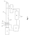
- FIG. 1 a schematic diagram of an embodiment of a battery charger suitable for use with the present invention will be shown, as will be discussed below the invention is susceptible of embodiments in many different forms. Since the use and structure of a battery charger are well known to the man skilled in the art only parts or components being relevant for the invention will be described in detail.
- the battery charger shown in fig. 1 is a primary switched charger comprising in a known manner a DC power circuit 8 connectable to the mains.
- the DC power circuit 8 comprises, in turn, a diode bridge (not shown), a smoothing capacitor (not shown).
- the charger comprises a high frequency transformer 14 having a primary winding 14a connected to the DC power circuit 8 and a secondary winding 14b.
- the smoothing capacitor stores energy as a high DC voltage.
- the transformer transforms the high voltage to a charging voltage.
- a control unit 16 comprising, inter alia, an electronic switch (not shown), like a field effect transistor FET, arranged to the DC power circuit and the transformer capable of chopping up the DC power from the DC power circuit into pulses, and controlling and modulating the signal.
- the control unit 16 comprises modulation circuitry (not shown) arranged for the modulation of the signal.
- a rectifying element (not shown), such as a diode, is arranged to the positive line, and a smoothing capacitor (not shown) is arranged between the positive and negative line.
- Control means 29 which will be described in more detail below, for controlling the charging process and the maintenance process of the battery charger is connected to the control unit 16 and to a measuring and amplifying circuitry 30 for measuring, detecting and feeding-back of voltage / current. Furthermore, the measuring and amplifying circuitry 30 for measuring, detecting and feeding-back of voltage / current is connected with the positive line 18 and the negative line 20. A feed-back line 32 is provided from the measuring and amplifying circuitry 30 to a modulation circuitry included in the control unit 16 for modulation. The details of the modulation circuitry will not be described in detail here, because it do not form part of the present invention and its function and design is well known to the man skilled in the art. Preferably, the signal is modulated using pulse width modulation (PWM).
- PWM pulse width modulation
- the present invention can be used with a number of other modulation methods, for example, pulse-position modulation (PPM) or pulse frequency modulation (PFM).
- PPM pulse-position modulation
- PFM pulse frequency modulation
- any necessary modifications of the circuits of the current device of the present invention in order to adapt the current device to the modulation method used are easily performed by the skilled man and are therefore not described herein.
- the measuring and amplifying circuitry 30 is also connected to the control means for transferring information regarding, for example, the voltage at the terminals of the battery.
- control means 29 comprises means for obtaining voltage information of the battery and/or the current delivered to the battery connected to the measuring and amplifying circuitry 30 for measuring, detecting and feeding-back of voltage / current.
- control means 29 can obtain the voltage information of the battery and/or the current directly from the measuring and amplifying circuitry 30 for measuring, detecting and feeding-back of voltage / current.
- control means 29 is arranged for bringing the control unit 16 to act or respond to control commands based upon the obtained information and memory means (not shown).
- the memory means may comprise a non-volatile memory chip (e.g. an EEPROM or FLASH memory chip) which is capable of storing data.
- control means can be realized by means of a processor including, inter alia, programmable instructions for executing the methods according to the present invention
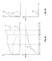
- the lines 50 and 51 indicate the voltage and the current, respectively, during a charging cycle of a battery having a "normal" internal resistance
- the line 52 indicates the charge build-up or increase, i.e. the conversion of active material, during the same charging cycle.
- the voltage 50 rises smoothly and the current 51 is almost constant when the charging is initiated, and the charge is, correspondingly, build-up in a smooth manner.
- the line 51 indicates that the current is almost constant or, in fact, slightly rising, the current may fall during this initial period of time, indicated by t1, in certain cases.
- the first period of time is denoted as the bulk period and during this period the charging voltage rises to the charge level, which normally is approximately 14,0-14,9 V, and the charge contained in the battery is successively build-up.
- the absorption period indicated by t2
- t3 the absorption period
- the period t1 has a length within a range from about 1h to about 20h
- the period t2 has a length within a range from about 1h to about 40h
- the period t3 has a length within a range from about 15 min. to about 6h
- the period t4 is unlimited.
- FIG. 2b graphs over voltage/current vs. time and charge vs. time, respectively, during a charging cycle of a battery having an increased internal voltage is shown in fig. 2b.
- the lines 53 and 54 indicate the voltage and current, respectively, during the charging cycle, and the line 55 indicates the charge build-up.
- the rise time of the voltage, see line 53 is very short when the charging voltage is applied to a battery having an increased internal voltage. In other words, the lapse of the increase of the voltage is almost instantaneous due to the high internal voltage. In fact, the rise time will be of the order of a few hundreds of microseconds.
- the voltage 53 rises rapidly to the maximum level of the battery and, correspondingly, the current 52 falls rapidly, which entails that a very low amount of charge is delivered to the battery, as indicated by the line 55.
- this rapid process caused by the high internal resistance makes it difficult or even impossible to charge the battery using a conventional battery charger.
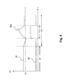
- fig. 2c graphs over voltage/current vs. time and charge vs. time, respectively, during a charging cycle of a battery having an increased internal voltage using the method for charging a battery in accordance with the present invention will be shown.
- the lines 56 and 57 indicate the voltage and the current, respectively, during the charging cycle, and the line 58 indicates the charge build-up during the charging cycle.
- a number of consecutive voltage pulses or bursts 56a having a duration of t5, t6, and t7, respectively, are applied to the battery.
- t5 is shorter than t6, which, in turn, is shorter that t7.
- Each of the periods t5-t7 can have a length in a range from about 50 ms up to several seconds.
- an offset time having a predetermined length can be introduced between consecutive voltage bursts, i.e. an interval period of time between two consecutive voltage bursts.
- the intervals can have successively increasing or decreasing lengths.
- a battery is connected to a battery charger, for example, the charger shown in fig. 1.
- the charging cycle is initiated, but due to a high internal resistance of the electrode plates of the battery, the voltage over the battery increases rapidly, which is sensed by control means 29 by means of the measuring and detecting circuitry 30.
- This triggers the control means 29 to activate a burst cycle period or, in other words, a sequence of consecutive voltage bursts, at step 64, as indicated by 56a in fig. 2c.
- each burst is a start of a "normal” charging followed by a disconnection of the voltage when the current has fallen below a predetermined level.
- this predetermined level is approximately 0,5 A.
- a small amount of charge is delivered to the battery, i.e. a small amount of active material is converted, during each burst. Consequently, the amount of converted active material grows successively.
- the control means 29 initiates a "normal" charging cycle. This is indicated by the fact that the current does not fall below the predetermined level following the applying of the charging voltage.
- the lines 80 and 82 indicates the voltage and current, respectively, during the maintenance charging in accordance with an embodiment of the method for maintenance charging of a battery according to the present invention.
- the voltage over the battery is held at a predetermined voltage level, preferably about 13,2-13,9 V. Further, the voltage level of the battery is approximately at 100 % during this period, about 97-98 %.
- This voltage level is maintained during a predetermined period of time, t9, and if the battery is not used during this period, the pulse or hystereses state, t10, will be initiated.
- a predetermined threshold value or level of battery capacity parameter which parameter preferably is the voltage indicated by v0 in fig. 4, one or more voltage pulses will be applied to or delivered to the battery in order to raise the voltage over this predetermined threshold level v0, indicated by a pulse having a duration of t11.
- the length of t11 depends of, inter alia, the size of the charger, the type of the battery and the condition of the battery. Generally, the period t11 is about 2-15 minutes and the voltage level is preferably 12,6-13 V.
- the current and voltage during the period t11 are, in principle, similar to a "normal" charging cycle, i.e. first, a constant or almost constant current with a rising voltage and, subsequently, a constant voltage with a falling current.
- the constant current part is either short, or almost non-existent.
- a normal charging cycle see fig. 2a, is initiated if the voltage falls below the predetermined threshold level of the battery capacity parameter.
- a function can be implemented that lay down conditions for that the current is not allowed to rise above a threshold value, typically 200 mA at a 100 Ah battery.
- a threshold value typically 200 mA at a 100 Ah battery.
- This function is useful, inter alia, in a back-up system. In this case the charger may remain in a float state since a current above this threshold indicates that the device or application connected to the battery constantly draws current of the battery.
- the maintenance charging is initiated by the control means 29 and the voltage over the battery is detected and locked to or held at preferably 13,2-13,9 V. This can initiated either manually by an user of the battery charger or automatically.
- the period of maintenance charging or float is set or predetermined to, for example, ten days. During this float period the charge of the battery is held at approximately 100 % of the capacity level and the battery can be used in application where maximum capacity is required. If the battery is not used during this float period, window charging will be initiated, i.e. a pulse or hysteres period, at step 92. If the battery is used during this period, the charger returns to the float mode.
- the voltage over the battery is monitored or detected and when or if the voltage falls below a predetermined threshold level or value of a battery capacity indicating parameter, which parameter in this embodiment is the voltage, one or more voltage pulses or burst will be applied, at step 96, in order to raise the voltage over the battery above the predetermined threshold level of the battery capacity parameter.
- a predetermined threshold level or value of a battery capacity indicating parameter which parameter in this embodiment is the voltage
- one or more voltage pulses or burst will be applied, at step 96, in order to raise the voltage over the battery above the predetermined threshold level of the battery capacity parameter.
- the length of these pulses depends of, inter alia, the size of the charger, the type of the battery and the condition of the battery. Generally, a period is about 2-15 minutes and the voltage level is preferably 12,6-13 V.
- the pulses can be applied during a predetermined period of time.
- the battery capacity parameter can be the current instead of the voltage.
- the modifications required to the circuits of the charger in order to adapt it to current monitoring are easily carried out by a man skilled in the art.
- a normal charging cycle see fig. 2a, can be initiated when the level of battery capacity parameter falls below the predetermined threshold level instead of window charging.
Claims (10)
- Procédé de chargement de batterie mis en oeuvre au niveau d'un chargeur de batterie comprenant des moyens de connexion destinés à une connexion aux bornes d'une batterie à charger, des moyens pour détecter une tension entre les bornes d'une batterie connectée, et des moyens de commande pour initier un cycle de salves, caractérisé en ce qu'il comporte les étapes consistant à :appliquer une tension au niveau d'une batterie connectée ;détecter la tension présente sur la batterie connectée pour détecter une augmentation de la tension sur ladite batterie afin d'identifier si la résistance interne de la batterie a augmenté par comparaison à un état normal ;initier un cycle de salves si ladite résistance interne est identifiée comme augmentée, dans lequel une pluralité de salves consécutives de tension est appliquée à une batterie connectée pour être chargée, chaque salve ayant une durée d'au moins de l'ordre des mS et chaque salve délivrant une quantité de charge à la batterie et abaissant, de ce fait, successivement la résistance interne de la batterie ; etinitier un cycle de charge pour charger la batterie connectée lorsque ledit cycle de salves est achevé.
- Procédé selon la revendication 1, dans lequel chaque salve présente une durée se situant dans une plage allant de 50 mS environ à plusieurs secondes.
- Procédé selon la revendication 1 ou 2, dans lequel l'étape consistant à initier un cycle de salves comprend, de plus, les étapes consistant à :appliquer une salve de tension à la batterie lorsque ladite tension sur la batterie a atteint un premier niveau prédéterminé ;déconnecter ladite salve de tension lorsque ladite tension sur la batterie a atteint un second niveau prédéterminé ;appliquer de nouveau ladite salve de tension à la batterie lorsque ladite tension sur la batterie a atteint le premier niveau prédéterminé.
- Procédé selon la revendication 1 ou 2, dans lequel l'étape consistant à initier un cycle de salves comprend l'étape consistant à :appliquer lesdites salves de tension avec un décalage de temps prédéterminé entre deux salves consécutives.
- Procédé selon la revendication 1, caractérisé en ce qu'il comprend, de plus, les étapes consistant à :maintenir la tension sur la batterie à un niveau prédéterminé pendant un laps de temps prédéterminé ;enregistrer un paramètre de capacité d'alimentation par batterie lorsque ledit laps de temps prédéterminé s'est écoulé ; etappliquer au moins une impulsion de tension si ledit paramètre tombe au-dessous d'un niveau de seuil prédéterminé.
- Procédé selon la revendication 5, dans lequel ledit paramètre de capacité d'alimentation par batterie prédéterminé est la tension présente sur la batterie connectée.
- Procédé selon les revendications 5 ou 6 dans lequel l'étape d'application comprend l'étape consistant à :appliquer des impulsions de tension jusqu'à ce que la tension présente sur la batterie ait atteint au moins ledit niveau prédéterminé.
- Procédé selon les revendications 5 à 7, dans lequel l'étape d'application comprend l'étape consistant à :appliquer des impulsions de tension pendant un laps de temps prédéterminé.
- Support pouvant être lu par ordinateur comprenant des instructions pour conduire un ordinateur à exécuter un procédé selon l'une quelconque des revendications précédentes.
- Chargeur de batterie comprenant des moyens de connexion connectés aux lignes de sortie du chargeur, des moyens de connexion destinés à une connexion avec les bornes d'une batterie à charger, des moyens pour détecter une tension présente sur une batterie connectée, et des moyens de commande, caractérisé en ce que lesdits moyens de commande sont connectés aux dits moyens de détection et agencés pour exécuter les procédés selon l'une quelconque des revendications 1 à 8.
Priority Applications (1)
| Application Number | Priority Date | Filing Date | Title |
|---|---|---|---|
| EP06120525A EP1744432B1 (fr) | 2003-04-30 | 2004-04-28 | Procédés de charge de batteries |
Applications Claiming Priority (2)
| Application Number | Priority Date | Filing Date | Title |
|---|---|---|---|
| SE0301252A SE525604E5 (sv) | 2003-04-30 | 2003-04-30 | Metod för laddning av ett batteri, datorläsbart medium samt batteriladdare |
| PCT/SE2004/000641 WO2004098021A1 (fr) | 2003-04-30 | 2004-04-28 | Procedes mis en oeuvre au niveau d'un chargeur de batterie |
Related Child Applications (2)
| Application Number | Title | Priority Date | Filing Date |
|---|---|---|---|
| EP06120525A Division EP1744432B1 (fr) | 2003-04-30 | 2004-04-28 | Procédés de charge de batteries |
| EP06120525.8 Division-Into | 2006-09-12 |
Publications (3)
| Publication Number | Publication Date |
|---|---|
| EP1618643A1 EP1618643A1 (fr) | 2006-01-25 |
| EP1618643B1 true EP1618643B1 (fr) | 2007-04-25 |
| EP1618643B2 EP1618643B2 (fr) | 2013-03-20 |
Family
ID=20291160
Family Applications (2)
| Application Number | Title | Priority Date | Filing Date |
|---|---|---|---|
| EP04730146A Active EP1618643B2 (fr) | 2003-04-30 | 2004-04-28 | Procedes mis en oeuvre au niveau d'un chargeur de batterie |
| EP06120525A Active EP1744432B1 (fr) | 2003-04-30 | 2004-04-28 | Procédés de charge de batteries |
Family Applications After (1)
| Application Number | Title | Priority Date | Filing Date |
|---|---|---|---|
| EP06120525A Active EP1744432B1 (fr) | 2003-04-30 | 2004-04-28 | Procédés de charge de batteries |
Country Status (7)
| Country | Link |
|---|---|
| US (1) | US7541778B2 (fr) |
| EP (2) | EP1618643B2 (fr) |
| AT (2) | ATE360910T1 (fr) |
| DE (1) | DE602004006109D1 (fr) |
| ES (2) | ES2286632T5 (fr) |
| SE (1) | SE525604E5 (fr) |
| WO (1) | WO2004098021A1 (fr) |
Cited By (2)
| Publication number | Priority date | Publication date | Assignee | Title |
|---|---|---|---|---|
| US9331364B2 (en) | 2014-02-04 | 2016-05-03 | Nissan North America, Inc. | Lithium sulfur battery pulse charging method and pulse waveform |
| US9379417B2 (en) | 2014-02-04 | 2016-06-28 | Nissan North America, Inc. | Lithium sulfur battery cathode electrode surface treatment during discharge |
Families Citing this family (13)
| Publication number | Priority date | Publication date | Assignee | Title |
|---|---|---|---|---|
| US20080007216A1 (en) * | 2006-07-10 | 2008-01-10 | Greatbatch Ltd. | Method To Reduce Resistance For Lithium/Silver Vanadium Oxide Electrochemical Cells |
| US8269465B2 (en) * | 2007-09-27 | 2012-09-18 | Pulsetech Products Corporation | Battery charging circuit generating an oscillating triangular waveform to remove sulphate from battery plates |
| US20100164437A1 (en) * | 2008-10-24 | 2010-07-01 | Mckinley Joseph P | Battery formation and charging system and method |
| EP2299556B1 (fr) | 2009-09-18 | 2019-07-03 | CTEK Sweden AB | Chargement de batterie et système de fourniture d'énergie électrique et système fonctionnant sur batterie |
| US8947050B2 (en) * | 2010-03-11 | 2015-02-03 | Ford Global Technologies, Llc | Charging of vehicle battery based on indicators of impedance and health |
| US9753093B2 (en) * | 2010-03-11 | 2017-09-05 | Ford Global Technologies, Llc | Vehicle and method of diagnosing battery condition of same |
| KR20130025668A (ko) * | 2011-09-02 | 2013-03-12 | 삼성전기주식회사 | 패드형 전극 접점 충전 장치 |
| US9991730B2 (en) | 2011-09-07 | 2018-06-05 | Johnson Controls Technology Company | Battery charging devices and systems |
| AU2012321042B2 (en) * | 2011-10-03 | 2016-02-11 | Megapulse Australia Pty Ltd | An improved battery conditioning apparatus |
| DE102011087496A1 (de) * | 2011-11-30 | 2013-06-27 | H-Tech Ag | Verfahren und Vorrichtung zum Laden von wiederaufladbaren Zellen |
| CN103579704A (zh) * | 2012-08-06 | 2014-02-12 | 腾讯科技(深圳)有限公司 | 一种充电管理方法及装置 |
| EP3123589A1 (fr) * | 2014-03-25 | 2017-02-01 | TEK GLOBAL S.r.l. | Appareil et procédé de charge de batteries |
| CN111600366B (zh) * | 2019-02-20 | 2023-06-16 | 联合汽车电子有限公司 | 车辆充电机软启动方法 |
Citations (3)
| Publication number | Priority date | Publication date | Assignee | Title |
|---|---|---|---|---|
| DE4308538A1 (de) * | 1993-03-17 | 1994-09-22 | Rotermund Ulli | Verfahren und Vorrichtung zum Regenerieren von Spannungsquellen in Form galvanischer Elemente, insbesondere von Primärelementen |
| WO1996017426A1 (fr) * | 1994-11-30 | 1996-06-06 | 3266991 Manitoba, Ltd. | Procede de charge et de conditionnement de batteries |
| US20020033691A1 (en) * | 2000-06-30 | 2002-03-21 | Rolfes Michael J. | Automatic battery charger with voltage controlled charging and ripple voltage test |
Family Cites Families (14)
| Publication number | Priority date | Publication date | Assignee | Title |
|---|---|---|---|---|
| US5063341A (en) * | 1990-10-16 | 1991-11-05 | Gali Carl E | Lead acid battery rejuvenator and charger |
| EP0623986B1 (fr) * | 1993-05-05 | 1998-04-29 | Sgs-Thomson Microelectronics Pte Ltd. | Chargeur de batterie |
| EP0623987B1 (fr) * | 1993-05-05 | 1999-07-07 | STMicroelectronics Pte Ltd. | Chargeur de batterie |
| US5592068A (en) * | 1993-05-28 | 1997-01-07 | William E. Gregory | Lead acid battery rejuvenator |
| JPH0888026A (ja) * | 1994-09-16 | 1996-04-02 | Canon Inc | 充電装置 |
| US5998968A (en) * | 1997-01-07 | 1999-12-07 | Ion Control Solutions, Llc | Method and apparatus for rapidly charging and reconditioning a battery |
| KR20000006763A (ko) * | 1999-01-21 | 2000-02-07 | 장영진 | 배터리(납축전지)의 효율적 사용을 위한 수명연장 장치 |
| US6252373B1 (en) * | 1999-04-26 | 2001-06-26 | Ion Control Solutions | Apparatus for rapidly charging and reconditioning a battery |
| US6127804A (en) * | 1999-09-10 | 2000-10-03 | Oglesbee; John Wendell | Lithium ion charging means and method using ionic relaxation control |
| EP1734421A3 (fr) * | 2000-08-11 | 2007-12-19 | Seiko Epson Corporation | Appareil électronique et procédé de commande de l'appareil électronique |
| US6362601B1 (en) * | 2000-11-17 | 2002-03-26 | Curtis Instruments, Inc. | Method of battery charge restoration based on estimated battery plate deterioration and/or based on battery state of health |
| US6867568B1 (en) * | 2001-08-13 | 2005-03-15 | John Olson | Battery finish charge device |
| US7345450B2 (en) * | 2002-02-19 | 2008-03-18 | V Ector Products, Inc. | Microprocessor controlled booster apparatus with polarity protection |
| US6707272B1 (en) * | 2002-11-22 | 2004-03-16 | Motorola, Inc. | Pulse charging circuit and method |
-
2003
- 2003-04-30 SE SE0301252A patent/SE525604E5/sv not_active IP Right Cessation
-
2004
- 2004-04-28 AT AT04730146T patent/ATE360910T1/de not_active IP Right Cessation
- 2004-04-28 DE DE602004006109T patent/DE602004006109D1/de active Active
- 2004-04-28 EP EP04730146A patent/EP1618643B2/fr active Active
- 2004-04-28 ES ES04730146T patent/ES2286632T5/es active Active
- 2004-04-28 US US10/554,910 patent/US7541778B2/en active Active
- 2004-04-28 AT AT06120525T patent/ATE539477T1/de active
- 2004-04-28 EP EP06120525A patent/EP1744432B1/fr active Active
- 2004-04-28 ES ES06120525T patent/ES2380043T3/es active Active
- 2004-04-28 WO PCT/SE2004/000641 patent/WO2004098021A1/fr active IP Right Grant
Patent Citations (3)
| Publication number | Priority date | Publication date | Assignee | Title |
|---|---|---|---|---|
| DE4308538A1 (de) * | 1993-03-17 | 1994-09-22 | Rotermund Ulli | Verfahren und Vorrichtung zum Regenerieren von Spannungsquellen in Form galvanischer Elemente, insbesondere von Primärelementen |
| WO1996017426A1 (fr) * | 1994-11-30 | 1996-06-06 | 3266991 Manitoba, Ltd. | Procede de charge et de conditionnement de batteries |
| US20020033691A1 (en) * | 2000-06-30 | 2002-03-21 | Rolfes Michael J. | Automatic battery charger with voltage controlled charging and ripple voltage test |
Cited By (2)
| Publication number | Priority date | Publication date | Assignee | Title |
|---|---|---|---|---|
| US9331364B2 (en) | 2014-02-04 | 2016-05-03 | Nissan North America, Inc. | Lithium sulfur battery pulse charging method and pulse waveform |
| US9379417B2 (en) | 2014-02-04 | 2016-06-28 | Nissan North America, Inc. | Lithium sulfur battery cathode electrode surface treatment during discharge |
Also Published As
| Publication number | Publication date |
|---|---|
| WO2004098021A1 (fr) | 2004-11-11 |
| SE525604C2 (sv) | 2005-03-22 |
| EP1744432B1 (fr) | 2011-12-28 |
| ES2286632T5 (es) | 2013-07-24 |
| EP1618643A1 (fr) | 2006-01-25 |
| SE0301252L (sv) | 2004-10-31 |
| ES2286632T3 (es) | 2007-12-01 |
| ATE360910T1 (de) | 2007-05-15 |
| US7541778B2 (en) | 2009-06-02 |
| DE602004006109D1 (de) | 2007-06-06 |
| ES2380043T3 (es) | 2012-05-08 |
| SE525604E5 (sv) | 2013-10-22 |
| ATE539477T1 (de) | 2012-01-15 |
| EP1618643B2 (fr) | 2013-03-20 |
| US20060132096A1 (en) | 2006-06-22 |
| EP1744432A2 (fr) | 2007-01-17 |
| EP1744432A3 (fr) | 2008-07-09 |
Similar Documents
| Publication | Publication Date | Title |
|---|---|---|
| US5237259A (en) | Charging method for secondary battery | |
| EP1618643B1 (fr) | Procedes mis en oeuvre au niveau d'un chargeur de batterie | |
| US5929593A (en) | Charging control apparatus using variable intermittent current charging | |
| US8018204B2 (en) | Compact ultra fast battery charger | |
| TWI762522B (zh) | 控制裝置、平衡校正裝置及蓄電系統 | |
| US20130002199A1 (en) | Charging of Li-ion Batteries | |
| MXPA97003852A (es) | Carga y acondicionamiento de acumuladores | |
| JP2007325324A (ja) | 充電システム、電池パックおよびその充電方法 | |
| CA2369519A1 (fr) | Appareil et procede de recuperation de batteries au plomb sulfate | |
| KR20210061235A (ko) | 납산 배터리 교체 시스템 | |
| US6420853B1 (en) | Battery charger capable of accurately determining fully charged condition regardless of batteries with different charge chracteristics | |
| JPH11341694A (ja) | 二次電池の充電方法 | |
| JP3796918B2 (ja) | バッテリ装置 | |
| JP2001298872A (ja) | 電力貯蔵システム | |
| KR20030020933A (ko) | 배터리 팩의 방전 재생 회로 | |
| US6469473B1 (en) | Method and apparatus for using pulse current to extend the functionality of a battery | |
| JP3420325B2 (ja) | 2次電池の充電回路 | |
| JP2003189498A (ja) | 二次電池の充電方法及び二次電池の充電器 | |
| JP2002315225A (ja) | 電池パック及び該電池パックを電源とする外部ホスト機器システム | |
| JPH09285018A (ja) | 電池パック | |
| JP2004064975A (ja) | 無停電電源装置 | |
| JP2622851B2 (ja) | 2次電池の充電装置 | |
| JPS63245232A (ja) | 充電器 | |
| JPH09289041A (ja) | 電池パック | |
| JPH06150977A (ja) | 充電回路 |
Legal Events
| Date | Code | Title | Description |
|---|---|---|---|
| PUAI | Public reference made under article 153(3) epc to a published international application that has entered the european phase |
Free format text: ORIGINAL CODE: 0009012 |
|
| 17P | Request for examination filed |
Effective date: 20051031 |
|
| AK | Designated contracting states |
Kind code of ref document: A1 Designated state(s): AT BE BG CH CY CZ DE DK EE ES FI FR GB GR HU IE IT LI LU MC NL PL PT RO SE SI SK TR |
|
| AX | Request for extension of the european patent |
Extension state: AL HR LT LV MK |
|
| 17Q | First examination report despatched |
Effective date: 20060703 |
|
| DAX | Request for extension of the european patent (deleted) | ||
| RAP1 | Party data changed (applicant data changed or rights of an application transferred) |
Owner name: CREATOR TEKNISK UTVECKLING AB |
|
| GRAP | Despatch of communication of intention to grant a patent |
Free format text: ORIGINAL CODE: EPIDOSNIGR1 |
|
| GRAS | Grant fee paid |
Free format text: ORIGINAL CODE: EPIDOSNIGR3 |
|
| GRAA | (expected) grant |
Free format text: ORIGINAL CODE: 0009210 |
|
| AK | Designated contracting states |
Kind code of ref document: B1 Designated state(s): AT BE BG CH CY CZ DE DK EE ES FI FR GB GR HU IE IT LI LU MC NL PL PT RO SE SI SK TR |
|
| PG25 | Lapsed in a contracting state [announced via postgrant information from national office to epo] |
Ref country code: DE Free format text: LAPSE BECAUSE OF FAILURE TO SUBMIT A TRANSLATION OF THE DESCRIPTION OR TO PAY THE FEE WITHIN THE PRESCRIBED TIME-LIMIT Effective date: 20070425 Ref country code: CH Free format text: LAPSE BECAUSE OF FAILURE TO SUBMIT A TRANSLATION OF THE DESCRIPTION OR TO PAY THE FEE WITHIN THE PRESCRIBED TIME-LIMIT Effective date: 20070425 Ref country code: LI Free format text: LAPSE BECAUSE OF FAILURE TO SUBMIT A TRANSLATION OF THE DESCRIPTION OR TO PAY THE FEE WITHIN THE PRESCRIBED TIME-LIMIT Effective date: 20070425 Ref country code: FI Free format text: LAPSE BECAUSE OF FAILURE TO SUBMIT A TRANSLATION OF THE DESCRIPTION OR TO PAY THE FEE WITHIN THE PRESCRIBED TIME-LIMIT Effective date: 20070425 |
|
| REG | Reference to a national code |
Ref country code: GB Ref legal event code: FG4D |
|
| REG | Reference to a national code |
Ref country code: IE Ref legal event code: FG4D |
|
| REG | Reference to a national code |
Ref country code: CH Ref legal event code: EP |
|
| REF | Corresponds to: |
Ref document number: 602004006109 Country of ref document: DE Date of ref document: 20070606 Kind code of ref document: P |
|
| PG25 | Lapsed in a contracting state [announced via postgrant information from national office to epo] |
Ref country code: SE Free format text: LAPSE BECAUSE OF FAILURE TO SUBMIT A TRANSLATION OF THE DESCRIPTION OR TO PAY THE FEE WITHIN THE PRESCRIBED TIME-LIMIT Effective date: 20070725 |
|
| PG25 | Lapsed in a contracting state [announced via postgrant information from national office to epo] |
Ref country code: PT Free format text: LAPSE BECAUSE OF FAILURE TO SUBMIT A TRANSLATION OF THE DESCRIPTION OR TO PAY THE FEE WITHIN THE PRESCRIBED TIME-LIMIT Effective date: 20070925 |
|
| REG | Reference to a national code |
Ref country code: CH Ref legal event code: PL |
|
| PG25 | Lapsed in a contracting state [announced via postgrant information from national office to epo] |
Ref country code: AT Free format text: LAPSE BECAUSE OF FAILURE TO SUBMIT A TRANSLATION OF THE DESCRIPTION OR TO PAY THE FEE WITHIN THE PRESCRIBED TIME-LIMIT Effective date: 20070425 Ref country code: PL Free format text: LAPSE BECAUSE OF FAILURE TO SUBMIT A TRANSLATION OF THE DESCRIPTION OR TO PAY THE FEE WITHIN THE PRESCRIBED TIME-LIMIT Effective date: 20070425 |
|
| REG | Reference to a national code |
Ref country code: ES Ref legal event code: FG2A Ref document number: 2286632 Country of ref document: ES Kind code of ref document: T3 |
|
| EN | Fr: translation not filed | ||
| PG25 | Lapsed in a contracting state [announced via postgrant information from national office to epo] |
Ref country code: BE Free format text: LAPSE BECAUSE OF FAILURE TO SUBMIT A TRANSLATION OF THE DESCRIPTION OR TO PAY THE FEE WITHIN THE PRESCRIBED TIME-LIMIT Effective date: 20070425 |
|
| PG25 | Lapsed in a contracting state [announced via postgrant information from national office to epo] |
Ref country code: CZ Free format text: LAPSE BECAUSE OF FAILURE TO SUBMIT A TRANSLATION OF THE DESCRIPTION OR TO PAY THE FEE WITHIN THE PRESCRIBED TIME-LIMIT Effective date: 20070425 Ref country code: BG Free format text: LAPSE BECAUSE OF FAILURE TO SUBMIT A TRANSLATION OF THE DESCRIPTION OR TO PAY THE FEE WITHIN THE PRESCRIBED TIME-LIMIT Effective date: 20070725 Ref country code: SI Free format text: LAPSE BECAUSE OF FAILURE TO SUBMIT A TRANSLATION OF THE DESCRIPTION OR TO PAY THE FEE WITHIN THE PRESCRIBED TIME-LIMIT Effective date: 20070425 Ref country code: DK Free format text: LAPSE BECAUSE OF FAILURE TO SUBMIT A TRANSLATION OF THE DESCRIPTION OR TO PAY THE FEE WITHIN THE PRESCRIBED TIME-LIMIT Effective date: 20070425 Ref country code: MC Free format text: LAPSE BECAUSE OF NON-PAYMENT OF DUE FEES Effective date: 20070430 |
|
| PLBI | Opposition filed |
Free format text: ORIGINAL CODE: 0009260 |
|
| PG25 | Lapsed in a contracting state [announced via postgrant information from national office to epo] |
Ref country code: SK Free format text: LAPSE BECAUSE OF FAILURE TO SUBMIT A TRANSLATION OF THE DESCRIPTION OR TO PAY THE FEE WITHIN THE PRESCRIBED TIME-LIMIT Effective date: 20070425 |
|
| PLAX | Notice of opposition and request to file observation + time limit sent |
Free format text: ORIGINAL CODE: EPIDOSNOBS2 |
|
| 26 | Opposition filed |
Opponent name: PREMIER MERCHANDISES LIMITED Effective date: 20080122 Opponent name: FRONIUS INTERNATIONAL GMBH Effective date: 20080125 |
|
| PG25 | Lapsed in a contracting state [announced via postgrant information from national office to epo] |
Ref country code: FR Free format text: LAPSE BECAUSE OF FAILURE TO SUBMIT A TRANSLATION OF THE DESCRIPTION OR TO PAY THE FEE WITHIN THE PRESCRIBED TIME-LIMIT Effective date: 20071221 Ref country code: GR Free format text: LAPSE BECAUSE OF FAILURE TO SUBMIT A TRANSLATION OF THE DESCRIPTION OR TO PAY THE FEE WITHIN THE PRESCRIBED TIME-LIMIT Effective date: 20070726 |
|
| NLR1 | Nl: opposition has been filed with the epo |
Opponent name: PREMIER MERCHANDISES LIMITED Opponent name: FRONIUS INTERNATIONAL GMBH |
|
| PG25 | Lapsed in a contracting state [announced via postgrant information from national office to epo] |
Ref country code: RO Free format text: LAPSE BECAUSE OF FAILURE TO SUBMIT A TRANSLATION OF THE DESCRIPTION OR TO PAY THE FEE WITHIN THE PRESCRIBED TIME-LIMIT Effective date: 20070425 Ref country code: IE Free format text: LAPSE BECAUSE OF NON-PAYMENT OF DUE FEES Effective date: 20070430 |
|
| PLBB | Reply of patent proprietor to notice(s) of opposition received |
Free format text: ORIGINAL CODE: EPIDOSNOBS3 |
|
| PG25 | Lapsed in a contracting state [announced via postgrant information from national office to epo] |
Ref country code: FR Free format text: LAPSE BECAUSE OF FAILURE TO SUBMIT A TRANSLATION OF THE DESCRIPTION OR TO PAY THE FEE WITHIN THE PRESCRIBED TIME-LIMIT Effective date: 20070425 |
|
| GBPC | Gb: european patent ceased through non-payment of renewal fee |
Effective date: 20080428 |
|
| PG25 | Lapsed in a contracting state [announced via postgrant information from national office to epo] |
Ref country code: EE Free format text: LAPSE BECAUSE OF FAILURE TO SUBMIT A TRANSLATION OF THE DESCRIPTION OR TO PAY THE FEE WITHIN THE PRESCRIBED TIME-LIMIT Effective date: 20070425 |
|
| PG25 | Lapsed in a contracting state [announced via postgrant information from national office to epo] |
Ref country code: GB Free format text: LAPSE BECAUSE OF NON-PAYMENT OF DUE FEES Effective date: 20080428 |
|
| PG25 | Lapsed in a contracting state [announced via postgrant information from national office to epo] |
Ref country code: CY Free format text: LAPSE BECAUSE OF FAILURE TO SUBMIT A TRANSLATION OF THE DESCRIPTION OR TO PAY THE FEE WITHIN THE PRESCRIBED TIME-LIMIT Effective date: 20070425 |
|
| PG25 | Lapsed in a contracting state [announced via postgrant information from national office to epo] |
Ref country code: LU Free format text: LAPSE BECAUSE OF NON-PAYMENT OF DUE FEES Effective date: 20070428 |
|
| PG25 | Lapsed in a contracting state [announced via postgrant information from national office to epo] |
Ref country code: HU Free format text: LAPSE BECAUSE OF FAILURE TO SUBMIT A TRANSLATION OF THE DESCRIPTION OR TO PAY THE FEE WITHIN THE PRESCRIBED TIME-LIMIT Effective date: 20071026 Ref country code: TR Free format text: LAPSE BECAUSE OF FAILURE TO SUBMIT A TRANSLATION OF THE DESCRIPTION OR TO PAY THE FEE WITHIN THE PRESCRIBED TIME-LIMIT Effective date: 20070425 |
|
| REG | Reference to a national code |
Ref country code: NL Ref legal event code: SD Effective date: 20110628 |
|
| REG | Reference to a national code |
Ref country code: ES Ref legal event code: PC2A Owner name: CTEK SWEDEN AB Effective date: 20110804 |
|
| RAP2 | Party data changed (patent owner data changed or rights of a patent transferred) |
Owner name: CTEK SWEDEN AB |
|
| PUAH | Patent maintained in amended form |
Free format text: ORIGINAL CODE: 0009272 |
|
| STAA | Information on the status of an ep patent application or granted ep patent |
Free format text: STATUS: PATENT MAINTAINED AS AMENDED |
|
| 27A | Patent maintained in amended form |
Effective date: 20130320 |
|
| AK | Designated contracting states |
Kind code of ref document: B2 Designated state(s): AT BE BG CH CY CZ DE DK EE ES FI FR GB GR HU IE IT LI LU MC NL PL PT RO SE SI SK TR |
|
| REG | Reference to a national code |
Ref country code: NL Ref legal event code: T3 |
|
| REG | Reference to a national code |
Ref country code: ES Ref legal event code: DC2A Ref document number: 2286632 Country of ref document: ES Kind code of ref document: T5 Effective date: 20130724 |
|
| P01 | Opt-out of the competence of the unified patent court (upc) registered |
Effective date: 20230428 |
|
| PGFP | Annual fee paid to national office [announced via postgrant information from national office to epo] |
Ref country code: NL Payment date: 20230417 Year of fee payment: 20 |
|
| PGFP | Annual fee paid to national office [announced via postgrant information from national office to epo] |
Ref country code: IT Payment date: 20230418 Year of fee payment: 20 Ref country code: ES Payment date: 20230531 Year of fee payment: 20 |