EP1618074B1 - Schmelzen und läutern in wannen mit gekühlten wänden - Google Patents
Schmelzen und läutern in wannen mit gekühlten wänden Download PDFInfo
- Publication number
- EP1618074B1 EP1618074B1 EP04724597A EP04724597A EP1618074B1 EP 1618074 B1 EP1618074 B1 EP 1618074B1 EP 04724597 A EP04724597 A EP 04724597A EP 04724597 A EP04724597 A EP 04724597A EP 1618074 B1 EP1618074 B1 EP 1618074B1
- Authority
- EP
- European Patent Office
- Prior art keywords
- melt
- temperature
- melting
- eff
- per unit
- Prior art date
- Legal status (The legal status is an assumption and is not a legal conclusion. Google has not performed a legal analysis and makes no representation as to the accuracy of the status listed.)
- Expired - Lifetime
Links
- 238000002844 melting Methods 0.000 title claims description 159
- 230000008018 melting Effects 0.000 title claims description 158
- 238000007670 refining Methods 0.000 title claims description 50
- 239000000155 melt Substances 0.000 claims description 216
- 238000000034 method Methods 0.000 claims description 68
- 239000011521 glass Substances 0.000 claims description 52
- 238000010438 heat treatment Methods 0.000 claims description 50
- 238000005265 energy consumption Methods 0.000 claims description 30
- 239000008188 pellet Substances 0.000 claims description 20
- 239000000289 melt material Substances 0.000 claims description 18
- 230000008569 process Effects 0.000 claims description 17
- 239000002241 glass-ceramic Substances 0.000 claims description 9
- 230000005587 bubbling Effects 0.000 claims description 8
- 230000005540 biological transmission Effects 0.000 claims description 5
- 230000004913 activation Effects 0.000 claims description 4
- 230000001939 inductive effect Effects 0.000 claims description 4
- 229910010272 inorganic material Inorganic materials 0.000 claims description 4
- 239000011147 inorganic material Substances 0.000 claims description 4
- 239000013256 coordination polymer Substances 0.000 claims 2
- 230000001965 increasing effect Effects 0.000 description 62
- 239000000203 mixture Substances 0.000 description 51
- 210000003625 skull Anatomy 0.000 description 51
- 239000000156 glass melt Substances 0.000 description 25
- 239000006060 molten glass Substances 0.000 description 25
- 238000006243 chemical reaction Methods 0.000 description 22
- 238000001816 cooling Methods 0.000 description 20
- 229910052751 metal Inorganic materials 0.000 description 18
- 239000002184 metal Substances 0.000 description 18
- 239000000463 material Substances 0.000 description 17
- 238000003756 stirring Methods 0.000 description 13
- 238000003723 Smelting Methods 0.000 description 12
- 230000007423 decrease Effects 0.000 description 12
- 230000001419 dependent effect Effects 0.000 description 11
- 239000007789 gas Substances 0.000 description 11
- 230000005855 radiation Effects 0.000 description 11
- 238000010586 diagram Methods 0.000 description 10
- BASFCYQUMIYNBI-UHFFFAOYSA-N platinum Substances [Pt] BASFCYQUMIYNBI-UHFFFAOYSA-N 0.000 description 10
- 230000008901 benefit Effects 0.000 description 9
- 230000008859 change Effects 0.000 description 9
- 230000009467 reduction Effects 0.000 description 8
- QVGXLLKOCUKJST-UHFFFAOYSA-N atomic oxygen Chemical compound [O] QVGXLLKOCUKJST-UHFFFAOYSA-N 0.000 description 7
- 239000012768 molten material Substances 0.000 description 7
- 239000001301 oxygen Substances 0.000 description 7
- 229910052760 oxygen Inorganic materials 0.000 description 7
- 230000001133 acceleration Effects 0.000 description 6
- 238000010410 dusting Methods 0.000 description 6
- 238000002474 experimental method Methods 0.000 description 6
- 238000002156 mixing Methods 0.000 description 6
- 229910052697 platinum Inorganic materials 0.000 description 6
- 239000011819 refractory material Substances 0.000 description 6
- 230000015572 biosynthetic process Effects 0.000 description 5
- 238000009792 diffusion process Methods 0.000 description 5
- 238000004090 dissolution Methods 0.000 description 5
- 230000017525 heat dissipation Effects 0.000 description 5
- 239000000047 product Substances 0.000 description 5
- 238000004904 shortening Methods 0.000 description 5
- 230000007704 transition Effects 0.000 description 5
- 229910008556 Li2O—Al2O3—SiO2 Inorganic materials 0.000 description 4
- 229910004298 SiO 2 Inorganic materials 0.000 description 4
- 239000000919 ceramic Substances 0.000 description 4
- 239000003795 chemical substances by application Substances 0.000 description 4
- 239000002826 coolant Substances 0.000 description 4
- 238000011161 development Methods 0.000 description 4
- 230000018109 developmental process Effects 0.000 description 4
- 238000010309 melting process Methods 0.000 description 4
- 239000000470 constituent Substances 0.000 description 3
- 230000006866 deterioration Effects 0.000 description 3
- 238000003780 insertion Methods 0.000 description 3
- 230000037431 insertion Effects 0.000 description 3
- MWUXSHHQAYIFBG-UHFFFAOYSA-N nitrogen oxide Inorganic materials O=[N] MWUXSHHQAYIFBG-UHFFFAOYSA-N 0.000 description 3
- 239000004033 plastic Substances 0.000 description 3
- 239000000843 powder Substances 0.000 description 3
- 238000000746 purification Methods 0.000 description 3
- 239000000126 substance Substances 0.000 description 3
- RYGMFSIKBFXOCR-UHFFFAOYSA-N Copper Chemical compound [Cu] RYGMFSIKBFXOCR-UHFFFAOYSA-N 0.000 description 2
- 241001295925 Gegenes Species 0.000 description 2
- PXHVJJICTQNCMI-UHFFFAOYSA-N Nickel Chemical compound [Ni] PXHVJJICTQNCMI-UHFFFAOYSA-N 0.000 description 2
- KDLHZDBZIXYQEI-UHFFFAOYSA-N Palladium Chemical compound [Pd] KDLHZDBZIXYQEI-UHFFFAOYSA-N 0.000 description 2
- VYPSYNLAJGMNEJ-UHFFFAOYSA-N Silicium dioxide Chemical compound O=[Si]=O VYPSYNLAJGMNEJ-UHFFFAOYSA-N 0.000 description 2
- 229910006404 SnO 2 Inorganic materials 0.000 description 2
- 239000005354 aluminosilicate glass Substances 0.000 description 2
- TZCXTZWJZNENPQ-UHFFFAOYSA-L barium sulfate Chemical compound [Ba+2].[O-]S([O-])(=O)=O TZCXTZWJZNENPQ-UHFFFAOYSA-L 0.000 description 2
- 239000011248 coating agent Substances 0.000 description 2
- 238000000576 coating method Methods 0.000 description 2
- 238000010924 continuous production Methods 0.000 description 2
- 229910052802 copper Inorganic materials 0.000 description 2
- 239000010949 copper Substances 0.000 description 2
- 230000008878 coupling Effects 0.000 description 2
- 238000010168 coupling process Methods 0.000 description 2
- 238000005859 coupling reaction Methods 0.000 description 2
- 238000001704 evaporation Methods 0.000 description 2
- 230000008020 evaporation Effects 0.000 description 2
- 230000002349 favourable effect Effects 0.000 description 2
- 230000004907 flux Effects 0.000 description 2
- 230000009477 glass transition Effects 0.000 description 2
- 230000006698 induction Effects 0.000 description 2
- 238000009413 insulation Methods 0.000 description 2
- 238000004519 manufacturing process Methods 0.000 description 2
- -1 platinum metals Chemical class 0.000 description 2
- 230000001105 regulatory effect Effects 0.000 description 2
- 210000002023 somite Anatomy 0.000 description 2
- 241000894007 species Species 0.000 description 2
- XOLBLPGZBRYERU-UHFFFAOYSA-N tin dioxide Chemical compound O=[Sn]=O XOLBLPGZBRYERU-UHFFFAOYSA-N 0.000 description 2
- 229910001887 tin oxide Inorganic materials 0.000 description 2
- 238000012546 transfer Methods 0.000 description 2
- XLYOFNOQVPJJNP-UHFFFAOYSA-N water Substances O XLYOFNOQVPJJNP-UHFFFAOYSA-N 0.000 description 2
- VYZAMTAEIAYCRO-UHFFFAOYSA-N Chromium Chemical compound [Cr] VYZAMTAEIAYCRO-UHFFFAOYSA-N 0.000 description 1
- 229910000831 Steel Inorganic materials 0.000 description 1
- 239000004809 Teflon Substances 0.000 description 1
- 229920006362 Teflon® Polymers 0.000 description 1
- 238000013019 agitation Methods 0.000 description 1
- 239000000956 alloy Substances 0.000 description 1
- 229910045601 alloy Inorganic materials 0.000 description 1
- 229910052782 aluminium Inorganic materials 0.000 description 1
- XAGFODPZIPBFFR-UHFFFAOYSA-N aluminium Chemical compound [Al] XAGFODPZIPBFFR-UHFFFAOYSA-N 0.000 description 1
- 229910000413 arsenic oxide Inorganic materials 0.000 description 1
- 229960002594 arsenic trioxide Drugs 0.000 description 1
- 239000007844 bleaching agent Substances 0.000 description 1
- 208000002352 blister Diseases 0.000 description 1
- 239000007795 chemical reaction product Substances 0.000 description 1
- 229910052804 chromium Inorganic materials 0.000 description 1
- 239000011651 chromium Substances 0.000 description 1
- 238000005352 clarification Methods 0.000 description 1
- 229910052681 coesite Inorganic materials 0.000 description 1
- 239000000110 cooling liquid Substances 0.000 description 1
- 230000007797 corrosion Effects 0.000 description 1
- 238000005260 corrosion Methods 0.000 description 1
- 229910052906 cristobalite Inorganic materials 0.000 description 1
- 239000013078 crystal Substances 0.000 description 1
- 230000003247 decreasing effect Effects 0.000 description 1
- 230000007547 defect Effects 0.000 description 1
- KTTMEOWBIWLMSE-UHFFFAOYSA-N diarsenic trioxide Chemical compound O1[As](O2)O[As]3O[As]1O[As]2O3 KTTMEOWBIWLMSE-UHFFFAOYSA-N 0.000 description 1
- 230000000694 effects Effects 0.000 description 1
- 238000010292 electrical insulation Methods 0.000 description 1
- 239000007772 electrode material Substances 0.000 description 1
- 238000007663 fining method Methods 0.000 description 1
- 238000010304 firing Methods 0.000 description 1
- 239000002803 fossil fuel Substances 0.000 description 1
- 239000006066 glass batch Substances 0.000 description 1
- PCHJSUWPFVWCPO-UHFFFAOYSA-N gold Chemical compound [Au] PCHJSUWPFVWCPO-UHFFFAOYSA-N 0.000 description 1
- 229910052737 gold Inorganic materials 0.000 description 1
- 239000010931 gold Substances 0.000 description 1
- 239000001257 hydrogen Substances 0.000 description 1
- 229910052739 hydrogen Inorganic materials 0.000 description 1
- 125000004435 hydrogen atom Chemical class [H]* 0.000 description 1
- 239000012535 impurity Substances 0.000 description 1
- 238000011835 investigation Methods 0.000 description 1
- 239000007788 liquid Substances 0.000 description 1
- 229910021645 metal ion Inorganic materials 0.000 description 1
- 229910052759 nickel Inorganic materials 0.000 description 1
- 239000005304 optical glass Substances 0.000 description 1
- 229910052763 palladium Inorganic materials 0.000 description 1
- 238000005453 pelletization Methods 0.000 description 1
- 238000002310 reflectometry Methods 0.000 description 1
- 239000011214 refractory ceramic Substances 0.000 description 1
- 229910052703 rhodium Inorganic materials 0.000 description 1
- 239000010948 rhodium Substances 0.000 description 1
- MHOVAHRLVXNVSD-UHFFFAOYSA-N rhodium atom Chemical compound [Rh] MHOVAHRLVXNVSD-UHFFFAOYSA-N 0.000 description 1
- 230000000630 rising effect Effects 0.000 description 1
- 239000000377 silicon dioxide Substances 0.000 description 1
- 238000000365 skull melting Methods 0.000 description 1
- 239000005361 soda-lime glass Substances 0.000 description 1
- 239000007787 solid Substances 0.000 description 1
- 239000010959 steel Substances 0.000 description 1
- 229910052682 stishovite Inorganic materials 0.000 description 1
- 229910052905 tridymite Inorganic materials 0.000 description 1
Images


Classifications
-
- C—CHEMISTRY; METALLURGY
- C03—GLASS; MINERAL OR SLAG WOOL
- C03B—MANUFACTURE, SHAPING, OR SUPPLEMENTARY PROCESSES
- C03B5/00—Melting in furnaces; Furnaces so far as specially adapted for glass manufacture
- C03B5/02—Melting in furnaces; Furnaces so far as specially adapted for glass manufacture in electric furnaces, e.g. by dielectric heating
- C03B5/021—Melting in furnaces; Furnaces so far as specially adapted for glass manufacture in electric furnaces, e.g. by dielectric heating by induction heating
-
- C—CHEMISTRY; METALLURGY
- C03—GLASS; MINERAL OR SLAG WOOL
- C03B—MANUFACTURE, SHAPING, OR SUPPLEMENTARY PROCESSES
- C03B5/00—Melting in furnaces; Furnaces so far as specially adapted for glass manufacture
- C03B5/02—Melting in furnaces; Furnaces so far as specially adapted for glass manufacture in electric furnaces, e.g. by dielectric heating
- C03B5/027—Melting in furnaces; Furnaces so far as specially adapted for glass manufacture in electric furnaces, e.g. by dielectric heating by passing an electric current between electrodes immersed in the glass bath, i.e. by direct resistance heating
- C03B5/03—Tank furnaces
-
- C—CHEMISTRY; METALLURGY
- C03—GLASS; MINERAL OR SLAG WOOL
- C03B—MANUFACTURE, SHAPING, OR SUPPLEMENTARY PROCESSES
- C03B5/00—Melting in furnaces; Furnaces so far as specially adapted for glass manufacture
- C03B5/16—Special features of the melting process; Auxiliary means specially adapted for glass-melting furnaces
- C03B5/18—Stirring devices; Homogenisation
- C03B5/193—Stirring devices; Homogenisation using gas, e.g. bubblers
-
- C—CHEMISTRY; METALLURGY
- C03—GLASS; MINERAL OR SLAG WOOL
- C03B—MANUFACTURE, SHAPING, OR SUPPLEMENTARY PROCESSES
- C03B5/00—Melting in furnaces; Furnaces so far as specially adapted for glass manufacture
- C03B5/16—Special features of the melting process; Auxiliary means specially adapted for glass-melting furnaces
- C03B5/24—Automatically regulating the melting process
-
- Y—GENERAL TAGGING OF NEW TECHNOLOGICAL DEVELOPMENTS; GENERAL TAGGING OF CROSS-SECTIONAL TECHNOLOGIES SPANNING OVER SEVERAL SECTIONS OF THE IPC; TECHNICAL SUBJECTS COVERED BY FORMER USPC CROSS-REFERENCE ART COLLECTIONS [XRACs] AND DIGESTS
- Y02—TECHNOLOGIES OR APPLICATIONS FOR MITIGATION OR ADAPTATION AGAINST CLIMATE CHANGE
- Y02P—CLIMATE CHANGE MITIGATION TECHNOLOGIES IN THE PRODUCTION OR PROCESSING OF GOODS
- Y02P40/00—Technologies relating to the processing of minerals
- Y02P40/50—Glass production, e.g. reusing waste heat during processing or shaping
- Y02P40/57—Improving the yield, e-g- reduction of reject rates
Definitions
- the invention relates to a method for melting and / or refining in melting or refining units with cooled walls.
- the aim of the invention is to provide a process with reduced energy consumption in the melting and / or refining of inorganic substances, preferably glasses, glass ceramics and crystals.
- the invention is preferably intended to be used in a melting or refining aggregate with cooled walls, such as, for example, in a skull crucible or a conductively heated pan.
- the prior art describes a number of chilled-wall melting units, in particular scull crucibles, which serve to melt glasses by means of high frequency.
- a crucible Under a high frequency heated skull crucible is understood here a crucible, which is formed of cooled metal tubes and is surrounded by a high-frequency coil. Between the metal pipes are columns, creating a direct Coupling of high-frequency energy in the molten glass is possible.
- a conductively heated trough or a conductively heated crucible is understood here to mean a trough or a crucible in which heat is supplied at least in part by direct or alternating currents introduced by means of electrodes.
- High-melting glasses which melt only above 1600 to 1700 ° C, can be melted in a melting aggregate with cooled walls, since the Skull Mrs from characteristic material constantly replicates also at high temperatures and thus protects against external impurities.
- the species-specific skull layer also prevents in particular that crucible material dissolved by the glass melt passes into the glass melt.
- special metal tubes must be used in extreme purity requirements, such as metal tubes made of platinum metals, aluminum tubes or plastic coated metal tubes.
- the temperature difference between the heated melt and the cooler wall area is a direct measure of the energy loss through heat dissipation. At higher melting or refining temperatures, this temperature difference is increased with and consequently the energy loss is increased by heat release.
- the energy loss per unit weight E v depends on the throughput. Assuming the same glass quality, an increase in throughput is usually associated with a temperature increase.
- the maximum melting temperature is determined by the refractory materials used. With the maximum melting temperature, the maximum throughput over the refractory materials is also given.
- the heat loss per unit area is much higher than the energy loss per unit area in the thermally well insulated walls of a conventional tub.
- the skull melting process is e.g. despite its considerable advantages over conventional tubs, it has only been used where conventional melting processes have failed.
- the object of the invention is now to find a method in which, on the one hand, the great advantages of a melting aggregate with cooled walls are maintained, but with which, on the other hand, it is possible to meet the energy requirement per unit weight of finished melt that occurs during melting in trays with cooled walls to lower significantly.
- T eff The temperature at which the energy consumption per unit weight E tot has its minimum is referred to below as T eff .
- T eff can be determined, for example, from experimental values, as explained for example with reference to the examples below.
- E tot stands for the total energy consumption per unit weight of molten glass and is made up of the useful heat per unit of weight E N and the energy loss per unit of weight E v .
- the melt heat energy is also fed directly, or directly in the melt energy is converted into heat energy. This can be done, for example, by means of appropriate devices by direct conductive Heating and / or done by direct inductive heating.
- the processes taking place in the melt depend on the absolute temperature. Accordingly, the range T eff -20 % to T eff + 20% is particularly related to the absolute temperature.
- the relative throughput is understood here to mean the throughput D [mass / time unit] relative to the melt quantity V * ⁇ in the melting aggregate, V denoting the volume and ⁇ the density of the melt.
- t denotes the average residence time
- the relative throughput thus has the dimension of a reciprocal time.
- the required residence time is determined by the result to be achieved by the method. According to one embodiment of the invention, mixtures are melted down with the method so that here the required residence time accordingly includes the melting time.
- the process melts the material to be melted, so that the required residence time comprises the time necessary for the refining. Also can be melted in an aggregate with cooled walls, as well as be purified. It accordingly includes the required residence time necessary for the melting and refining time.
- the required residence time is also understood to mean the average residence time of the melt in the melt aggregate.
- T eff - 20% to T eff + 20% proves to be particularly favorable for the energy consumption per unit weight of the melt.
- thermodynamic equilibria With very high throughputs or very short residence times of the melt in the smelting unit, not only the physical processes, such as, for example, the rate of ascent of the bubbles during refining play a role, but also the chemical reactions, in particular the kinetics, with which the thermodynamic equilibria in the melt Adjust melt.
- the kinetics of the adjustment of the thermodynamic equilibria are increased.
- the acceleration of the kinetics allows a sufficiently high throughput increase at high temperatures, so that the increased energy loss per unit weight at higher temperatures is more than compensated for by the adjusted throughput increase.
- a heating method is required, which can supply sufficient heat energy to the melt in order to bring at least a portion of the melt despite the cooling of the walls to the intended temperature can.
- the latent heat .DELTA.H comprises the reaction and / or phase transition heat during melting or glass transition of the melt, which is added for example in the form of mixtures and / or shards.
- the useful heat in particular the required useful heat for the refining, is thus directly proportional to the throughput and the melting temperature.
- the useful heat per kg of molten glass E N is independent of the melting time and the melting process.
- the energy loss depends on the melting process.
- the required residence time ⁇ of the melt in the melting unit V is dependent on the respective reaction rate, for example the rate of dissolution of the batch or the ascent rate of the lautering bubbles.
- ⁇ 0 denotes the required residence time at a reference temperature T 0 .
- E v k * T * F 0 * 1 / ⁇ * ⁇ 0 * e + e / T
- the energy consumption per unit weight E tot of the melt is initially dependent on the residence time of the melt in the melting unit. Furthermore, the required residence time is temperature dependent. For example, refining at high temperatures is faster and the residence time required to achieve the desired result, such as a refining melt, is shortened.
- the inventors have surprisingly recognized that the increase of the melting temperature and the associated faster reaction rate in the melt results in a decreasing energy contribution E tot with increasing temperature, although more energy must be used to cool the walls of the melting unit and to heat the melt.
- the change of the energy consumption per unit weight E tot with the temperature is equal to the change of the useful heat per unit weight E N with the temperature plus the change of the energy loss per unit weight E v with the temperature.
- the change in the useful heat per unit weight with the temperature dE N / dT is constant for the heating of the melt and by definition equal to c p .
- the device for conductive heating of the melt comprises, according to one embodiment of the invention, cooled electrodes.
- the melt can be heated to high temperatures, which also exceed the application limit temperatures of suitable electrode materials, so that one for a low energy consumption favorable temperature can be adjusted.
- Such electrodes and melters for direct conductive heating of melts are also in the two previous German applications with the application numbers 102 56 657.7 and 102 56 594.5 described, the disclosure of which is fully made in this respect also the subject of the present application.
- the preferably large-area electrodes can be used with advantage in recesses of cooled walls of the unit.
- the melt can be heated with the aid of the cooled electrodes with alternating current of 50 Hz to 50 kHz, preferably from 2 kHz to 10 kHz.
- the electrode surfaces can advantageously be dimensioned so large that the current density for heating the melt at any point of the electrodes has more than 5 A / cm 2 .
- the electrodes have at least one, preferably two cooling circuits via which their cooling can be regulated.
- a cooling medium may preferably serve air and water.
- a fusing unit with conductive heating, or a development of the method according to the invention with conductive heating are also suitable for melts whose electrical conductivity is less than 10 -1 ⁇ -1 cm -1 , for example, for melts having an electrical conductivity in the range of 10 -. 3 ⁇ -1 cm -1 or preferably from 10 -2 ⁇ -1 cm -1 to 10 -1 ⁇ -1 cm -1
- the large-area electrodes which are a component of the cooled walls, contain at least one controllable cooling system.
- the electrodes preferably contain a double controllable cooling system, for example one for gas cooling and one for liquid cooling.
- the large-area cooled electrodes can be installed both in the walls of skull crucibles and in cooled ceramic walls.
- the device for high-frequency heating of the melt in a cooling unit with cooled walls comprises, according to an embodiment of the invention, a skull crucible which is surrounded by a radio-frequency coil.
- the skull crucible is made of cooled metal tubes. There are gaps between the metal tubes, allowing direct coupling of the high frequency into the molten glass.
- the method is also particularly preferably carried out as a continuous process, wherein the melt is supplied by means of appropriate facilities continuously melt and removed.
- the supplied melt can be supplied both in solid form as a mixture, as well as already as a melt.
- the removal of molten material is preferably carried out in molten form.
- the inventors have recognized that the disadvantages associated with the increase in temperature in conventional tubs due to the chemical attack of the tub material can be avoided when melting in aggregates with cooled walls.
- the walls of the melting unit must be able to be cooled down to such an extent that corrosion of the walls no longer takes place, even with very high convection of the molten glass.
- the inventors have further recognized that it is worthwhile in melt aggregates with cooled walls, the melt not only to the temperature T kon , which is just needed for the melting or refining process, but to a much higher temperature, and the To increase throughput according to the shorter required residence time. According to one embodiment of the invention, it is provided to heat at least a portion of the melt to more than 1700 ° C.
- the inventors have recognized that by increasing the temperature of the melt beyond T.sub.con , the physical processes and chemical reactions in the smelting unit are accelerated to such an extent that it is possible to increase the throughput per unit volume in a cooling unit with cooled walls to such an extent
- Increase of the melting temperature T is a decrease in energy loss per unit weight E v , that is, the energy gain or the reduction of energy loss through the increase in throughput is significantly greater than the additional energy consumption, the temperature increase of the melt and holding the melt in the Melting unit at the higher temperature is needed.
- the energy consumption per unit weight E tot ie the sum of energy loss per unit weight E v, in particular through the walls and the floor and the useful heat per unit weight E N for heating the melt, as explained above, passes through a minimum at T eff , provided the throughput is adapted to the required residence time t.
- T eff Even above T eff , operation of an aggregate may be advantageous, for example, to be able to work very quickly with high throughput due to the only slight increase in energy costs due to the slow increase in energy consumption in this area. However, in this case, the equipment cost is greater. Therefore, operation at a temperature below or up to T eff , that is, in a range of T eff -20 % to T eff, is preferred. It may also be that the desired temperature T eff can not be achieved. This depends inter alia on the composition of the melt. When the melt contains constituents below T eff already begin to evaporate, then the melt can be heated only to the evaporation temperature T verd of the relevant component of the melt, without changing the'gewünschte composition of the molten glass strong. If T verd is smaller than T eff then only a part of the maximum possible energy saving potential can be realized. The temperature T eff can not be achieved even if it is not possible to supply sufficient heat energy to the system.
- the maximum energy saving is achieved in many cases in a first approximation at a temperature at which the useful heat per unit weight E N to increase the melting temperature is equal to the energy loss per unit weight E v .
- a temperature lower than or equal to this temperature can be selected at which the useful heat per unit weight and the energy loss prp unit weight are equal.
- the change in the useful heat per unit weight for heating a glass melt with the temperature can, as already mentioned, be determined from the specific heat C p of the glass melt.
- the specific heat capacity c p of glass melts is between 1 and 2 kJ / (kg * K), for example 1.175 kJ / (kg * K) for soda-lime glass and 1.5 kJ / (kg * K) for an alumino -Silicate glass for the production of glass ceramics.
- the change in the energy loss of the wall as a function of the temperature can be measured, for example, directly by measuring the temperature of the cooling liquid used to cool the walls as a function of the temperature.
- the change of the throughput with the temperature depends on the respectively required residence time t of the melt in the melt volume.
- the change in throughput with temperature can be determined either experimentally directly or by changing the reaction rate with temperature.
- the absolute mass flow rate can be adjusted, or on the other hand, a desired absolute Mass flow rate can be maintained and the melt volume or the dimensions of the unit to be adjusted. This is for example advantageous if the unit is part of a production line with a given mass flow rate.
- the size of the melting unit can be determined for the given throughput.
- the energy consumption per unit weight E tot in melters with cooled walls is partly determined by the additional useful heat per unit weight E N for heating the melt from the temperature T konc to the temperature T eff . This means that the lower the temperature T eff, the greater the energy savings of cooling units with cooled walls.
- the method according to the invention may additionally comprise suitable measures for shortening the required residence time at a given temperature and quality.
- the residence time can be effectively shortened, inter alia, if the melt additionally mixed and thus the reaction rate is increased.
- the direct heat radiation into the melt and the cooled walls for example the skull walls in a skull crucible, when heating with high frequency or alternating current, cause larger temperature differences than in a conventional well.
- the large temperature difference seeks to compensate by convection.
- the inventors have recognized that by setting a viscosity of ⁇ 10 3 dPas preferably of ⁇ 10 2 dPas in at least one region of the melt and a temperature difference of the melt between an inner and an outer region of the melt of> 150 K preferably> 250 K. the required residence time can be significantly reduced.
- convection in the crucible increases very strongly at these temperature and viscosity ratios in the melt. This has, for example, during the refining that in particular small bubbles are entrained by the convection and thus reach the surface much faster than just by the physical buoyancy.
- a shortening of the required residence time can advantageously also be achieved, inter alia, when the melt is stirred with a stirrer and / or by bubbling.
- bubbling gas is introduced into the melt with one or more nozzles, in particular in the bottom region of the crucible used, wherein the stirring of the melt is carried out by the rising of the gas bubbles. Additional stirring is advantageous, inter alia, if the viscosity of the melt is above 10 3 dPas. In this case, the convection of the melt in the melting unit is often insufficient to stir mixtures into the molten glass.
- the method according to the invention also has the advantages that, on the one hand, it consumes less energy at high melting temperatures between T kon and T eff than on T kon and, on the other hand, it is particularly well suited for high temperature bleaching agents.
- the inventors have recognized that by increasing the melting temperature, the chemical reactions in the melting unit can be accelerated so that it is possible to stir the mixture into the melt without the melt deteriorate later quality of the molten material.
- the increase in the melting temperature is even more limited than with refining.
- the tub attack of the reflowing batch is generally greater than the tub attack of the glass melt.
- the melting temperature must not be too high for such tubs.
- the glass melt after melting usually has to be purified.
- the temperature of the glass melt must be increased after melting to release the refining agent.
- the higher refining temperature is, as already described, limited by the tub attack.
- cooling with cooled walls allows for high convection, as either the skull layer of the skull crucible is constantly renewed or the walls of the melting unit are cooled to such an extent that even with high convection there is no reaction between wall and melt with dissolution of the wall material comes.
- melted material can also be supplied in the form of mixtures, which is placed on the surface of the melt.
- the throughput to be achieved depends, among other things, on the speed with which the mixture can be applied to the molten glass and how quickly the mixture melts below the surface.
- the energy saving by increasing the melting rate at higher temperature is greater than the energy loss by heating and holding the molten glass at the higher temperature.
- the inventors have recognized that increasing the melting rate with temperature is of the same order of magnitude as increasing the refining speed. It has thus been found that from a temperature at which the viscosity of the melt ⁇ 10 3 dPas is preferably ⁇ 10 2 dPas and the temperature difference between an inner and an outer region of the melt> 150 K is preferably> 250 K, the melting rate increases greatly in the supply of molten material in the form of mixtures in the melting unit.
- the abrupt increase in the melting rate is due to a large increase in convective flow in the melt.
- the viscosity of the melt is lowered and, on the other hand, the temperature difference between the edge of the crucible and the center of the crucible is produced.
- the temperature difference between crucible edge and crucible center is also strongly dependent on the radiation transmission of the melt, for example in the molten glass.
- the temperature difference is higher with dark glasses than with highly transparent glasses.
- the greater the temperature difference in the melt the greater is the endeavor Balance difference. If the viscosity of the melt drops to ⁇ 10 3 dPas, preferably to ⁇ 10 2 dPas, then strong convection begins in the melt.
- the inventors have recognized that by the increased convection at higher temperatures, the shear forces on the mixture to be dissolved are significantly increased and therefore also leads to a much faster melting of the mixture.
- the mixture can also be advantageously stirred into the melt to further reduce the required residence time.
- the mixing of the mixture can also be carried out by stirring the melt as described above by means of a stirrer or by bubbling. By stirring the batch into the melt, the mixture has a much larger melting surface available in the volume drop melt achieved in this way than when it melts on the surface.
- the melting rate can also be increased if the mixture is not placed in powder form on the surface of the melt, but the melt is added in the form of pellets, wherein the pellets either by stirring, bubbling or high convection in the melt is stirred.
- the inventors have found that under advantageous development of the method according to the invention when melted the batch in a melting unit with cooled walls, the melting rate can be increased considerably by the addition of the batch in the form of pellets.
- the increased chemical reaction rate which is due to the increase in temperature, can be implemented much better.
- the mixture in the melt is immediately surrounded by melt and the chemical reactions can start immediately.
- a convection flow can be advantageously ensured that the pellets constantly come into contact with new melt.
- the dusting of the batch also plays a greater role than in a slow insert, as is usual in conventional tubs otherwise.
- a dusting of the mixture is to avoid the direct heating of the melt with high frequency or alternating current, is also advantageous because the dusting and evaporation products can be deposited on the cooled walls and condense and thus easily lead to electrical flashovers.
- the inventors have also recognized that, when using chilled wall aggregates such as skull crucibles, the heat loss across the cooled walls, in addition to the temperature of the melt, also depends on the type and thickness of the skull layer. When forming a crystalline layer, the heat loss is significantly lower than with transparent glass layers.
- the inventors have recognized that in glasses with high heat radiation transmission, the energy loss is greater than in glasses with a low heat radiation transmission. For example, the loss of energy is less with colored glass than with transparent glass.
- the cooled walls for example the water-cooled metal tubes of a skull crucible, have a heat radiation-reflecting surface. It is irrelevant whether the walls are directly heat-reflecting or whether they have a heat-reflecting layer or coating.
- Glasses and glass products can preferably be produced by the method according to the invention. Glasses or glass products produced in this way are characterized in that the ratio of Sn 2+ to Sn T , where T denotes the total concentration, is between 0.20 to 0.70, preferably between 0.25 and 0.60 and particularly preferably between 0.30 and 0.50.
- FIGS. 1A to 1C different views of a first embodiment of a device for melting inorganic materials are shown.
- the Device is designated as a whole with 1.
- Fig. 1B shows a view of the device 1 from the perspective of the arrow B in Fig. 1A.
- Fig. 1C represents a top view as seen in the direction of arrow C in Fig. 1B
- the crucible is made of tubes 7, through which coolant is passed during operation of the device for cooling the vessel.
- copper is suitable because of its good thermal conductivity.
- copper does not have a particularly high strength, so that pipes made of highly mechanically or temperature-resistant metal, in particular those made of high-strength or heat-resistant steel, may also be suitable.
- the tubes of the skull crucible can also be equipped with a heat radiation-reflecting surface.
- the tubes 7 may be provided with a platinum or gold coating, which in particular may also be polished in order to increase the reflectivity.
- rhodium, chromium, nickel or palladium, as well as their alloys can be used for this purpose.
- a refractory collar 13 is arranged on the crucible in the region of the molten bath surface.
- the collar protrudes laterally beyond the edge of the pot.
- the bottom of the collar is also cooled.
- At the edge of the collar 13 is closed by a refractory ceramic wall.
- an inlet 9 and a drain 10 is incorporated with Schmelzgutrinnen 11, wherein the inlet serves as means for the continuous supply of melt and the flow as a means for the continuous removal of melt, said by the inlet and outlet in the melt pool surface of the melting vessel melted material is continuously added and removed.
- a bottom drain 15 is arranged, through which the crucible can be emptied.
- the skull tubes may also protrude from the surface of the molten bath and, for example, be plastic-coated, at least in the region of the surface of the molten bath, in order to increase the chemical resistance.
- a plastic Teflon is particularly suitable for this purpose.
- two electrodes 5 are arranged as a device for conductive heating of the melt in corresponding recesses in the side wall .16 of the melting vessel.
- the electrodes have coolant connections 6 as part of a device for cooling the electrodes, via which coolant is passed through channels in the interior of the electrodes.
- the electrodes 5 replace a part of the side wall 16 of the melting vessel 3, wherein the electrodes 5 are also mounted opposite to the melting vessel.
- the electrodes 5 are held over a large area.
- the electrodes 5 replace at least 15% of the wall surface of the melting vessel in the region of the melt.
- a heating current is passed through the melt via the electrodes 5, whereby the electrodes 5 are fastened insulated relative to the melting vessel 3, so that no current can flow over the walls of the melting vessel and reduce the heating power.
- the wall elements of the melting vessel may be divided into segments isolated from each other.
- the electrodes are further arranged on the same sides of the device 1 as the inlet 9 and outlet 10 of the melt, so that the heating current flows between the electrodes substantially in the direction of the main flow direction of the melt or opposite. .
- the electrodes are dimensioned over a large area, so that the current emerging from the electrodes into the melt does not exceed a current density of 5 A / cm 2 at any point of the melt-contacting surface.
- a heating current preferably with an alternating current frequency in a range from 50 Hz to 50 kHz, particularly preferably with an alternating current frequency in a range from 2 kHz to 10 kHz, is heated by the device in the melting vessel 3 by means of a device for generating alternating current directed.
- nozzles 18 are arranged, with which bubbling gas can be blown into the melt to additionally stir the melt.
- Fig. 1B additionally shows schematically a power supply 20, which supplies the electrodes 5 with the heating current for the melt.
- the power supply 20 is designed adjustable, the control by means of a program-controlled Computing device 24 takes place. With the computing device 24, temperature readings of one or more temperature sensors 22 are detected and the heating current output of the power supply is regulated.
- the computing device is used in conjunction with the temperature sensors 20 as means for setting a suitable temperature in the melt, which is at least T eff - 20% to T eff + 20%, to allow energy-saving operation.
- the computing device 20 which can be adjusted via suitable interfaces to a controllable device for conveying melted material and the throughput, so that the required average residence time in the unit is not exceeded.
- the computing device can therefore advantageously also function as part of a device for adjusting the relative throughput of melt to the required residence time in the melt.
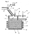
- Fig. 2 1 shows a further embodiment of a device 1.
- This embodiment also comprises a crucible 3 with metal tubes 7 designed as a skull crucible.
- the metal tubes 7 are fastened to a base plate via electrical insulation 40.
- the bottom plate of this embodiment of a device 1 comprises a first bottom plate 44, on which a cooled, quartzally slid second bottom plate 44 is arranged, so that also cooled walls are present in the bottom region. Accordingly, all wall components in contact with the melt are cooled so that heating of at least a portion of the melt above the application limit temperature of the materials of these wall components is possible.
- This embodiment of the device 1 has a device for inductive heating for heating the melt in the melting vessel 3.
- This device comprises an induction coil 26 which surrounds the melting vessel or the melt present in the melting vessel.
- a drain 10 is provided with gutter 11 as a means for the continuous removal of molten material.
- the device 1 also has a device for the continuous supply of molten material.
- a device for the continuous supply of molten material includes in the basis of Fig. 2 As shown embodiment, a conveyor belt 28, with which melt in the form of mixture and / or shards 34 is supplied through an insertion opening 32 and placed on the melt surface.
- a wall 38 prevents melted material that has not melted on the melt surface from being able to get directly to the outlet 10 and thus helps to maintain the required residence time of melted material in the melting vessel 3.
- the speed of the batch insert and thus the throughput or the relative throughput can be adjusted or controlled by the conveying speed of the conveyor belt 28.
- the control takes place via a program-controlled computing device 24.
- the computing device 24 in conjunction with the controllable drive 30 allows an adjustment of the deposit speed of the melt and thus the throughput of the device 1.
- the conveyor belt in conjunction with the controlled by a computing device 24 drive 30 thus also means for adjusting the relative throughput to the required residence time of melt in the melting unit, or in the crucible 3.
- a trough burner 46 and an overflow trough 11 arranged above the overflow burner 48 are arranged. With the aid of these burners melted material can be melted, in particular for starting the device 1, so that the molten melt material couples to the high-frequency field of the coil 26.
- the throughput in a refining aggregate can be increased by at least a factor of 5 without sacrificing quality by increasing the temperature from 1700 ° C. to 1900 ° C.
- the Fig. 3 shows a diagram in which the temperature (left) and the oxygen partial pressure, pO 2 (right) of a melt are plotted against the duration of the experiment.
- Fig. 3 was a mixture with an As 2 O 3 - refining agent melted at 1550 ° C and heated successively to 1600 ° C and 1650 ° C.
- the P o2 value first increases very rapidly and then gradually decreases.
- the As 2 O 5 content also decreases.
- the decrease in the pO 2 value is the faster, the higher the melting temperature.
- the inventive method has the advantage that the example in the DE 199 39 779 described Hochtemperaturläuterstoff can be used.
- SnO 2 can be used particularly advantageously at refining temperatures above 1700 ° C.
- the tin oxide, SnO 2 releases the major amount of oxygen above about 1700 ° C.
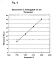
- Fig. 4 shows again for clarity, the Sn 2+ content as a function of the temperature in aluminosilicate glasses, which after 1 to 4 hours melting at corresponding Temperature have been produced. Plotted is the proportion of Sn 2+ in percent of the total Sn T.
- Glass produced in this way thus exhibits a temperature-dependent ratio of Sn 2+ to Sn T.
- This ratio of Sn 2+ to Sn T shows Fig. 4 Glasses with a value of greater than 0.25, but glasses are preferred having a value which is greater than 0.35, and particularly preferred are glasses having such a value, which is greater than 0.45.
- Glass products made from such glasses typically will then have the same ratios of Sn 2+ to Sn T unless significant high temperature processes have been performed which achieve similar temperatures to those discussed above.
- the refining at high melting temperatures (above 1650 ° C) with high-temperature redox refining agents has the additional advantage that at lower temperatures around 1400 ° C to 1500 ° C, the formation of bubbles on platinum is strongly suppressed. Platinum is particularly useful as a melt contact material for the Electrodes suitable for conductive heating.
- the high-temperature redox refining agents at these low temperatures resume the oxygen that forms during the hydrogen diffusion through the platinum.
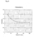
- the inventors have surprisingly found that the energy loss through the water-cooled walls of a skull crucible between 1700 ° C and 2400 ° C does not increase exponentially, as one would expect, but only linearly
- Fig. 5 shows a diagram in which the heat flux density j is plotted by the, skull wall in W / cm 2 against the temperature of the melt.
- the heat flux density through the walls of a skull crucible was measured with a Li 2 O-Al 2 O 3 -SiO 2 - glass-ceramic melt as a function of the temperature above 1650 ° C.
- the inventors have found that, for example, when heating the molten glass of a Li 2 O-Al 2 O 3 -SiO 2 glass ceramic from 1700 ° C to 1900 ° C and refining the glass melt at 1900 ° C and a throughput increase by a factor of 5 in a 100 liter skull crucible the energy requirement per unit weight E tot , including the greater energy loss through the water cooled metal tubes of Skulltiegels and the additional useful heat for further heating of the melt is reduced by at least a factor of 2.5 ,
- a 100 liter Skull-Läutertiegel is connected to a conventional ceramic smelting unit.
- 1000 kg of molten glass per day are refined in the 100 liter skull crucible.
- the skull crucible shows an energy loss of 153 kW above the water-cooled metal pipes. This gives a heat loss of 3672 kWh / d or, with a throughput of 1000 kg / d, an energy loss per unit weight of 3.67 kWh / kg.
- the glass melt is then heated in the skull crucible from 1700 ° C to 1900 ° C.
- the inventors have further recognized that it is also possible to use a smaller melt aggregate with cooled walls at the higher melting temperature, rather than increasing throughput.
- the energy loss of the 100 liter skull crucible is again 153 KW or 3672 kWh / d.
- the energy loss per unit weight again amounts to 3.67 kWh / kg.
- the energy consumption per unit weight E tot is reduced at least by a factor of 1.5.
- the energy consumption E tot ie the sum of energy loss per unit weight E v through the walls and the floor and the useful heat per unit weight E N for heating the melt, at T eff a minimum, provided that the throughput of the. required residence time t is adjusted.
- T eff is estimated for the refining.
- the temperature dependence of the energy loss per unit weight E v is calculated from the temperature dependence of the heat loss and the temperature dependence of the required residence time of the melt in the melt volume.
- the temperature dependence of the useful energy per unit weight E N is 0.42 Wh / (kg * K).
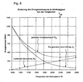
- Fig. 7 shows the energy loss per unit weight E v through the walls of the melter and the additional useful heat per unit weight E N as a function of the melting temperature.
- the weight unit is expediently in tons and the energy given in kilowatt hours.
- the energy loss per unit weight is about the same as the useful heat per unit weight to increase the melting energy.
- the total energy consumption per unit weight E tot of the melt passes through a minimum at 2100 ° C, or 2373 ° K.
- the minimum energy consumption in this example is about 2100 ° C, or 2377 ° K. This temperature corresponds to T eff .
- the energy loss / t or the energy loss per unit weight E v achieved in this example at about 1950 ° C the same size as the additional useful energy / t or the useful energy per unit weight E N for heating the Melt from 1500 ° C (T kon ) up to 1950 ° C. At 1950 ° C E v E N.
- Example 3 Melting at a constant melt volume
- the residence time of the melt in the smelting aggregate can be significantly reduced with increasing temperature even during smelting of mixtures and thus the throughput can be increased. Even when smelting a mixture, T eff can be determined over the residence time t of the glass melt in the smelting unit.
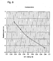
- the Ln of the reaction rate k for the dissolution of SiO 2 is plotted against 1 / T * 1000 (in degrees Kelvin, ° K) of the melt. From Figure 9, the activation energy for the melting of the mixture can be estimated, since the SiO 2 dissolves from the batch constituents of the melt with the slowest. It can be seen from Fig. 9 that the rate of dissolution of the batch increases exponentially with temperature. The melting rate of SiO 2 decreases by about 100 K per 100 K. a factor of 3 too. These values were measured on a glass for making ampoules for the pharmaceutical industry.
- T eff can be shifted to lower temperatures by additional measures to increase the throughput.
- the melting speed is increased by a factor of 1.5 to 5 in addition to the temperature-dependent, higher melting rate due to the increased convection and the greater shear forces.
- the melting rate similar to convection, can be increased by a factor of 1.5 to 5.
Landscapes
- Chemical & Material Sciences (AREA)
- Engineering & Computer Science (AREA)
- Materials Engineering (AREA)
- Organic Chemistry (AREA)
- Chemical Kinetics & Catalysis (AREA)
- Electrochemistry (AREA)
- Glass Melting And Manufacturing (AREA)
- Re-Forming, After-Treatment, Cutting And Transporting Of Glass Products (AREA)
Applications Claiming Priority (2)
| Application Number | Priority Date | Filing Date | Title |
|---|---|---|---|
| DE10314955A DE10314955B4 (de) | 2003-04-02 | 2003-04-02 | Verfahren zum Schmelzen anorganischer Materialien |
| PCT/EP2004/003416 WO2004087587A1 (de) | 2003-04-02 | 2004-03-31 | Schmelzen und läutern in wannen mit gekühlten wänden |
Publications (2)
| Publication Number | Publication Date |
|---|---|
| EP1618074A1 EP1618074A1 (de) | 2006-01-25 |
| EP1618074B1 true EP1618074B1 (de) | 2009-07-15 |
Family
ID=33016112
Family Applications (1)
| Application Number | Title | Priority Date | Filing Date |
|---|---|---|---|
| EP04724597A Expired - Lifetime EP1618074B1 (de) | 2003-04-02 | 2004-03-31 | Schmelzen und läutern in wannen mit gekühlten wänden |
Country Status (6)
| Country | Link |
|---|---|
| US (1) | US8424342B2 (enExample) |
| EP (1) | EP1618074B1 (enExample) |
| JP (1) | JP4750017B2 (enExample) |
| DE (1) | DE10314955B4 (enExample) |
| TW (1) | TW200508165A (enExample) |
| WO (1) | WO2004087587A1 (enExample) |
Families Citing this family (35)
| Publication number | Priority date | Publication date | Assignee | Title |
|---|---|---|---|---|
| DE10329718B4 (de) * | 2003-07-02 | 2006-04-27 | Schott Ag | Verfahren und Vorrichtung zum Einschmelzen von anorganischen Substanzen, insbesondere von Gläsern |
| DE102006003535A1 (de) * | 2006-01-24 | 2007-08-02 | Schott Ag | Verfahren zur Temperaturbeeinflussung einer Schmelze |
| DE102006003534A1 (de) * | 2006-01-24 | 2007-08-02 | Schott Ag | Verfahren und Vorrichtung zum Korrosionsschutz von Elektroden bei der Temperaturbeeinflussung einer Schmelze |
| DE102006039225B4 (de) * | 2006-08-22 | 2010-06-10 | Schott Ag | Verfahren und Vorrichtung zum Hochtemperatureinschmelzen und -läutern von Materialien |
| US9096453B2 (en) * | 2012-06-11 | 2015-08-04 | Johns Manville | Submerged combustion melting processes for producing glass and similar materials, and systems for carrying out such processes |
| US8707740B2 (en) | 2011-10-07 | 2014-04-29 | Johns Manville | Submerged combustion glass manufacturing systems and methods |
| US8997525B2 (en) | 2010-06-17 | 2015-04-07 | Johns Manville | Systems and methods for making foamed glass using submerged combustion |
| US9021838B2 (en) | 2010-06-17 | 2015-05-05 | Johns Manville | Systems and methods for glass manufacturing |
| US9032760B2 (en) | 2012-07-03 | 2015-05-19 | Johns Manville | Process of using a submerged combustion melter to produce hollow glass fiber or solid glass fiber having entrained bubbles, and burners and systems to make such fibers |
| US10322960B2 (en) | 2010-06-17 | 2019-06-18 | Johns Manville | Controlling foam in apparatus downstream of a melter by adjustment of alkali oxide content in the melter |
| US9533905B2 (en) | 2012-10-03 | 2017-01-03 | Johns Manville | Submerged combustion melters having an extended treatment zone and methods of producing molten glass |
| FR2991759B1 (fr) * | 2012-06-12 | 2014-06-20 | Saint Gobain Isover | Installation de fusion de verre |
| WO2014055199A1 (en) | 2012-10-03 | 2014-04-10 | Johns Manville | Methods and systems for destabilizing foam in equipment downstream of a submerged combustion melter |
| US9227865B2 (en) | 2012-11-29 | 2016-01-05 | Johns Manville | Methods and systems for making well-fined glass using submerged combustion |
| US9016090B2 (en) | 2013-06-12 | 2015-04-28 | Hamid Hojaji | Glass microspheres comprising sulfide, and methods of producing glass microspheres |
| CN107124878B (zh) * | 2014-08-21 | 2020-09-29 | 康宁股份有限公司 | 防止层叠玻璃制品中的气泡的方法以及由此形成的层叠玻璃制品 |
| US10196296B2 (en) | 2015-01-17 | 2019-02-05 | Hamid Hojaji | Fluid permeable and vacuumed insulating microspheres and methods of producing the same |
| US9751792B2 (en) | 2015-08-12 | 2017-09-05 | Johns Manville | Post-manufacturing processes for submerged combustion burner |
| US10041666B2 (en) | 2015-08-27 | 2018-08-07 | Johns Manville | Burner panels including dry-tip burners, submerged combustion melters, and methods |
| US10670261B2 (en) | 2015-08-27 | 2020-06-02 | Johns Manville | Burner panels, submerged combustion melters, and methods |
| US9815726B2 (en) | 2015-09-03 | 2017-11-14 | Johns Manville | Apparatus, systems, and methods for pre-heating feedstock to a melter using melter exhaust |
| US9982884B2 (en) | 2015-09-15 | 2018-05-29 | Johns Manville | Methods of melting feedstock using a submerged combustion melter |
| US10837705B2 (en) | 2015-09-16 | 2020-11-17 | Johns Manville | Change-out system for submerged combustion melting burner |
| US10081563B2 (en) | 2015-09-23 | 2018-09-25 | Johns Manville | Systems and methods for mechanically binding loose scrap |
| US10144666B2 (en) | 2015-10-20 | 2018-12-04 | Johns Manville | Processing organics and inorganics in a submerged combustion melter |
| US9783445B1 (en) * | 2016-06-15 | 2017-10-10 | Corning Incorporated | Method, system, and equipment for glass material processing as a function of crystal state |
| US10246362B2 (en) | 2016-06-22 | 2019-04-02 | Johns Manville | Effective discharge of exhaust from submerged combustion melters and methods |
| US10301208B2 (en) | 2016-08-25 | 2019-05-28 | Johns Manville | Continuous flow submerged combustion melter cooling wall panels, submerged combustion melters, and methods of using same |
| US10196294B2 (en) | 2016-09-07 | 2019-02-05 | Johns Manville | Submerged combustion melters, wall structures or panels of same, and methods of using same |
| US10233105B2 (en) | 2016-10-14 | 2019-03-19 | Johns Manville | Submerged combustion melters and methods of feeding particulate material into such melters |
| DE102018108418A1 (de) * | 2018-04-10 | 2019-10-10 | Schott Ag | Verfahren zur Herstellung von Glasprodukten sowie hierzu geeignete Vorrichtung |
| FR3116815B1 (fr) * | 2020-11-30 | 2023-04-28 | Saint Gobain Isover | Procede de traitement de dechets verriers |
| IT202200017172A1 (it) * | 2022-08-11 | 2024-02-11 | Claudio Berti | Forno a crogiolo per la fusione e la lavorazione artigianale del vetro, con riscaldamento a tecnologia ibrida ad elevata efficienza energetica |
| EP4342856A1 (en) * | 2022-09-21 | 2024-03-27 | Schott Ag | Method and apparatus for making a glass product and corresponding glass product |
| CN117492490B (zh) * | 2023-12-29 | 2024-04-16 | 山东兴诺工贸股份有限公司 | 一种基于数据分析的玻璃加工智能化温控系统 |
Family Cites Families (19)
| Publication number | Priority date | Publication date | Assignee | Title |
|---|---|---|---|---|
| NL278242A (enExample) | 1961-05-10 | |||
| FR1306851A (fr) | 1961-11-22 | 1962-10-19 | Glaverbel | Appareil pour la fusion de produits tels que le verre et procédé pour son exploitation |
| US3811860A (en) * | 1972-06-09 | 1974-05-21 | Ppg Industries Inc | Processing of stirring molten glass with bubbles from electrolysis |
| US4133969A (en) * | 1978-01-03 | 1979-01-09 | Zumbrunnen Allen D | High frequency resistance melting furnace |
| US4246433A (en) * | 1979-06-27 | 1981-01-20 | Toledo Engineering Co., Inc. | Square glass furnace with sidewall electrodes |
| US5738811A (en) * | 1995-05-16 | 1998-04-14 | Monofrax Inc. | Process for making fused-cast refractory products |
| FR2774085B3 (fr) * | 1998-01-26 | 2000-02-25 | Saint Gobain Vitrage | Procede de fusion et d'affinage de matieres vitrifiables |
| DE19822437C1 (de) * | 1998-05-19 | 1999-07-29 | Schott Glas | Verfahren zum physikalischen Läutern einer Flüssigkeit und Vorrichtung zur Durchführung des Verfahrens |
| DE19939781C2 (de) * | 1999-08-21 | 2003-06-18 | Schott Glas | Skulltiegel für das Erschmelzen oder das Läutern von anorganischen Substanzen, insbesondere von Gläsern und Glaskeramiken |
| DE19939771B4 (de) | 1999-08-21 | 2004-04-15 | Schott Glas | Verfahren zur Läuterung von Glasschmelzen |
| DE19939779C2 (de) * | 1999-08-21 | 2003-06-26 | Schott Glas | Vorrichtung und Verfahren zum kontinuierlichen Erschmelzen und Läutern von anorganischen Verbindungen, insbesondere von Gläsern und Glaskeramiken |
| DE19939785C2 (de) * | 1999-08-21 | 2003-12-18 | Schott Glas | Verfahren und Vorrichtung zum Herstellen von farbigen Gläsern |
| DE19939772C1 (de) * | 1999-08-21 | 2001-05-03 | Schott Glas | Skulltiegel für das Erschmelzen oder das Läutern von Gläsern |
| DE19939780C2 (de) * | 1999-08-21 | 2002-02-14 | Schott Glas | Skulltiegel für das Erschmelzen oder das Läutern von Gläsern oder Glaskeramiken |
| DE10003948B4 (de) * | 2000-01-29 | 2006-03-23 | Schott Ag | Verfahren zum Erschmelzen, Läutern und Homogenisieren von Glasschmelzen |
| DE10017701C2 (de) * | 2000-04-08 | 2002-03-07 | Schott Glas | Gefloatetes Flachglas |
| DE10041757C1 (de) * | 2000-08-25 | 2002-02-21 | Schott Glas | Verfahren und Vorrichtung zum Läutern von Glas |
| KR100432450B1 (ko) | 2000-12-21 | 2004-05-20 | 한국수력원자력 주식회사 | 중저준위 방사성 폐기물의 처리시스템 |
| DE10138108B4 (de) | 2001-08-03 | 2005-02-24 | Schott Ag | Verfahren zur Verminderung der Blasenbildung beim Herstellen von Gläsern |
-
2003
- 2003-04-02 DE DE10314955A patent/DE10314955B4/de not_active Expired - Fee Related
-
2004
- 2004-03-31 JP JP2006504934A patent/JP4750017B2/ja not_active Expired - Fee Related
- 2004-03-31 US US10/552,103 patent/US8424342B2/en not_active Expired - Fee Related
- 2004-03-31 WO PCT/EP2004/003416 patent/WO2004087587A1/de not_active Ceased
- 2004-03-31 EP EP04724597A patent/EP1618074B1/de not_active Expired - Lifetime
- 2004-04-01 TW TW093109069A patent/TW200508165A/zh unknown
Also Published As
| Publication number | Publication date |
|---|---|
| JP2006521991A (ja) | 2006-09-28 |
| EP1618074A1 (de) | 2006-01-25 |
| US8424342B2 (en) | 2013-04-23 |
| JP4750017B2 (ja) | 2011-08-17 |
| US20060291528A1 (en) | 2006-12-28 |
| WO2004087587A1 (de) | 2004-10-14 |
| DE10314955B4 (de) | 2008-04-17 |
| TW200508165A (en) | 2005-03-01 |
| DE10314955A1 (de) | 2004-10-21 |
Similar Documents
| Publication | Publication Date | Title |
|---|---|---|
| EP1618074B1 (de) | Schmelzen und läutern in wannen mit gekühlten wänden | |
| DE2904317C2 (de) | Verfahren zum Herstellen von geschmolzenem Glas | |
| DE102007008299B4 (de) | Verfahren zur Herstellung von Gläsern, wobei die chemische Reduktion von Bestandteilen vermieden wird | |
| EP1078889B1 (de) | Verfahren zur Läuterung von Glasschmelzen | |
| DE10393837B4 (de) | Verfahren und Vorrichtung zur Beheizung von Schmelzen | |
| DE10329718B4 (de) | Verfahren und Vorrichtung zum Einschmelzen von anorganischen Substanzen, insbesondere von Gläsern | |
| DE102006003535A1 (de) | Verfahren zur Temperaturbeeinflussung einer Schmelze | |
| DE102004004590B4 (de) | Fördereinrichtung für Glasschmelze sowie ein Verfahren zum Herstellen von Glasprodukten | |
| WO2003031353A2 (de) | Vorrichtung und verfahren zum kontaminationsarmen schmelzen von glas oder glaskeramik | |
| DE202020005894U1 (de) | Verwendung von Sulfat beim Läutern von durch Tauchverbrennung geschmolzenem Glas | |
| DE102009033501A1 (de) | Verfahren und Vorrichtung zum kontinuierlichen Schmelzen oder Läutern von Schmelzen | |
| EP1078890A1 (de) | Vorrichtung und Verfahren für das Läutern von Gläsern oder Glaskeramiken | |
| EP1127851B1 (de) | Verfahren und Vorrichtung zur Sauerstoffläuterung von Glasschmelzen | |
| EP1206420B1 (de) | Vorrichtung zum kontinuierlichen erschmelzen und läutern von anorganischen verbindungen, insbesondere von gläsern und glaskeramiken | |
| WO2007085397A1 (de) | Verfahren und vorrichtung zum korrosionsschutz von elektroden bei der temperaturbeeinflussung einer schmelze | |
| DE202020005891U1 (de) | Glasartikel und Behälter | |
| DE10348466A1 (de) | Vorrichtung und Verfahren zur Herstellung von hoch schmelzenden Gläsern oder Glaskeramiken sowie Glas oder Glaskeramik | |
| DE10257049B4 (de) | Verfahren zur Herstellung von Borosilicatgläsern, Boratgläsern und kristallisierenden borhaltigen Werkstoffen | |
| EP1206419B1 (de) | Verfahren und vorrichtung zum herstellen von farbigen gläsern | |
| DE19856797B4 (de) | Auskleidematerial für Glasschmelzöfen, Glasschmelzöfen und Verfahren zum Erzeugen von Glasprodukten | |
| EP3553034A1 (de) | Verfahren zur herstellung von glasprodukten sowie hierzu geeignete vorrichtung | |
| DE112021005112T5 (de) | Beschickungsvorrichtungsalkoven und Gemengebeschickungseinrichtung für eine Schmelzwanne | |
| DE1769848A1 (de) | Verfahren und Einrichtung zum Erhitzen,Schmelzen oder Erweichen von Stoffen in disperser Form,insbesondere zur Herstellung von diehtem oder poroesem Quarzgut,Quarzglas,Glas oder aehnlichen Stoffen | |
| DE10202024B4 (de) | Vorrichtung und Verfahren zum kontaminationsarmen Schmelzen einer Substanz | |
| EP0868404A1 (de) | Drehbarer widerstandsschmelzofen |
Legal Events
| Date | Code | Title | Description |
|---|---|---|---|
| PUAI | Public reference made under article 153(3) epc to a published international application that has entered the european phase |
Free format text: ORIGINAL CODE: 0009012 |
|
| 17P | Request for examination filed |
Effective date: 20051017 |
|
| AK | Designated contracting states |
Kind code of ref document: A1 Designated state(s): AT BE BG CH CY CZ DE DK EE ES FI FR GB GR HU IE IT LI LU MC NL PL PT RO SE SI SK TR |
|
| AX | Request for extension of the european patent |
Extension state: AL LT LV MK |
|
| DAX | Request for extension of the european patent (deleted) | ||
| RBV | Designated contracting states (corrected) |
Designated state(s): FR |
|
| REG | Reference to a national code |
Ref country code: DE Ref legal event code: 8566 |
|
| RIN1 | Information on inventor provided before grant (corrected) |
Inventor name: NUESSLE, GERHARD Inventor name: SCHMIDBAUER, WOLFGANG Inventor name: NAUMANN, KARIN Inventor name: LENTES, FRANK, THOMAS Inventor name: KIEFER, WERNER Inventor name: LEISTER, MICHAEL Inventor name: RAEKE, GUIDO Inventor name: RODEK, ERICH Inventor name: ROEMER, HILDEGARD Inventor name: OHMSTEDE, VOLKER |
|
| RIN1 | Information on inventor provided before grant (corrected) |
Inventor name: LEISTER, MICHAEL Inventor name: ROEMER, HILDEGARD Inventor name: KIEFER, WERNER Inventor name: NUESSLE, GERHARD Inventor name: SCHMIDBAUER, WOLFGANG Inventor name: RAEKE, GUIDO Inventor name: RODEK, ERICH Inventor name: NAUMANN, KARIN Inventor name: LENTES, FRANK, THOMAS Inventor name: OHMSTEDE, VOLKER |
|
| GRAP | Despatch of communication of intention to grant a patent |
Free format text: ORIGINAL CODE: EPIDOSNIGR1 |
|
| GRAS | Grant fee paid |
Free format text: ORIGINAL CODE: EPIDOSNIGR3 |
|
| GRAA | (expected) grant |
Free format text: ORIGINAL CODE: 0009210 |
|
| AK | Designated contracting states |
Kind code of ref document: B1 Designated state(s): FR |
|
| PLBE | No opposition filed within time limit |
Free format text: ORIGINAL CODE: 0009261 |
|
| STAA | Information on the status of an ep patent application or granted ep patent |
Free format text: STATUS: NO OPPOSITION FILED WITHIN TIME LIMIT |
|
| 26N | No opposition filed |
Effective date: 20100416 |
|
| REG | Reference to a national code |
Ref country code: FR Ref legal event code: PLFP Year of fee payment: 13 |
|
| PGFP | Annual fee paid to national office [announced via postgrant information from national office to epo] |
Ref country code: FR Payment date: 20160321 Year of fee payment: 13 |
|
| REG | Reference to a national code |
Ref country code: FR Ref legal event code: ST Effective date: 20171130 |
|
| PG25 | Lapsed in a contracting state [announced via postgrant information from national office to epo] |
Ref country code: FR Free format text: LAPSE BECAUSE OF NON-PAYMENT OF DUE FEES Effective date: 20170331 |