EP1618074B1 - Melting and refining in baths with cooled walls - Google Patents
Melting and refining in baths with cooled walls Download PDFInfo
- Publication number
- EP1618074B1 EP1618074B1 EP04724597A EP04724597A EP1618074B1 EP 1618074 B1 EP1618074 B1 EP 1618074B1 EP 04724597 A EP04724597 A EP 04724597A EP 04724597 A EP04724597 A EP 04724597A EP 1618074 B1 EP1618074 B1 EP 1618074B1
- Authority
- EP
- European Patent Office
- Prior art keywords
- melt
- temperature
- melting
- eff
- per unit
- Prior art date
- Legal status (The legal status is an assumption and is not a legal conclusion. Google has not performed a legal analysis and makes no representation as to the accuracy of the status listed.)
- Expired - Fee Related
Links
Images


Classifications
-
- C—CHEMISTRY; METALLURGY
- C03—GLASS; MINERAL OR SLAG WOOL
- C03B—MANUFACTURE, SHAPING, OR SUPPLEMENTARY PROCESSES
- C03B5/00—Melting in furnaces; Furnaces so far as specially adapted for glass manufacture
- C03B5/02—Melting in furnaces; Furnaces so far as specially adapted for glass manufacture in electric furnaces, e.g. by dielectric heating
- C03B5/021—Melting in furnaces; Furnaces so far as specially adapted for glass manufacture in electric furnaces, e.g. by dielectric heating by induction heating
-
- C—CHEMISTRY; METALLURGY
- C03—GLASS; MINERAL OR SLAG WOOL
- C03B—MANUFACTURE, SHAPING, OR SUPPLEMENTARY PROCESSES
- C03B5/00—Melting in furnaces; Furnaces so far as specially adapted for glass manufacture
- C03B5/02—Melting in furnaces; Furnaces so far as specially adapted for glass manufacture in electric furnaces, e.g. by dielectric heating
- C03B5/027—Melting in furnaces; Furnaces so far as specially adapted for glass manufacture in electric furnaces, e.g. by dielectric heating by passing an electric current between electrodes immersed in the glass bath, i.e. by direct resistance heating
- C03B5/03—Tank furnaces
-
- C—CHEMISTRY; METALLURGY
- C03—GLASS; MINERAL OR SLAG WOOL
- C03B—MANUFACTURE, SHAPING, OR SUPPLEMENTARY PROCESSES
- C03B5/00—Melting in furnaces; Furnaces so far as specially adapted for glass manufacture
- C03B5/16—Special features of the melting process; Auxiliary means specially adapted for glass-melting furnaces
- C03B5/18—Stirring devices; Homogenisation
- C03B5/193—Stirring devices; Homogenisation using gas, e.g. bubblers
-
- C—CHEMISTRY; METALLURGY
- C03—GLASS; MINERAL OR SLAG WOOL
- C03B—MANUFACTURE, SHAPING, OR SUPPLEMENTARY PROCESSES
- C03B5/00—Melting in furnaces; Furnaces so far as specially adapted for glass manufacture
- C03B5/16—Special features of the melting process; Auxiliary means specially adapted for glass-melting furnaces
- C03B5/24—Automatically regulating the melting process
-
- Y—GENERAL TAGGING OF NEW TECHNOLOGICAL DEVELOPMENTS; GENERAL TAGGING OF CROSS-SECTIONAL TECHNOLOGIES SPANNING OVER SEVERAL SECTIONS OF THE IPC; TECHNICAL SUBJECTS COVERED BY FORMER USPC CROSS-REFERENCE ART COLLECTIONS [XRACs] AND DIGESTS
- Y02—TECHNOLOGIES OR APPLICATIONS FOR MITIGATION OR ADAPTATION AGAINST CLIMATE CHANGE
- Y02P—CLIMATE CHANGE MITIGATION TECHNOLOGIES IN THE PRODUCTION OR PROCESSING OF GOODS
- Y02P40/00—Technologies relating to the processing of minerals
- Y02P40/50—Glass production, e.g. reusing waste heat during processing or shaping
- Y02P40/57—Improving the yield, e-g- reduction of reject rates
Description
Die Erfindung betrifft ein Verfahren zum Schmelzen und /oder Läutern in Schmelz- oder Läuteraggregaten mit gekühlten Wänden.The invention relates to a method for melting and / or refining in melting or refining units with cooled walls.
Ziel der Erfindung ist es, ein Verfahren mit verringertem Energieverbrauch beim Schmelzen und/oder Läutern von anorganischen Stoffen, vorzugsweise Gläsern, Glaskeramiken und Kristallen bereitzustellen. Bevorzugt soll die Erfindung in einem Schmelz- oder Läuteraggregat mit gekühlten Wänden, wie zum Beispiel in einem Skulltiegel, oder einer konduktiv geheizten Wanne Anwendung finden.The aim of the invention is to provide a process with reduced energy consumption in the melting and / or refining of inorganic substances, preferably glasses, glass ceramics and crystals. The invention is preferably intended to be used in a melting or refining aggregate with cooled walls, such as, for example, in a skull crucible or a conductively heated pan.
Aus dem Stand der Technik sind eine Reihe von Schmelzaggregaten mit gekühlten Wänden beschrieben, vor allem von Skulltiegeln, die zum Schmelzen von Gläsern mit Hilfe von Hochfrequenz dienen.The prior art describes a number of chilled-wall melting units, in particular scull crucibles, which serve to melt glasses by means of high frequency.
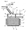
Unter einem Hochfrequenz beheizten Skulltiegel wird hier ein Tiegel verstanden, der aus gekühlten Metallrohren gebildet wird und mit einer Hochfrequenzspule umgeben ist. Zwischen den Metallrohren befinden sich Spalten, wodurch eine direkte Einkopplung der Hochfrequenzenergie in die Glasschmelze möglich ist.Under a high frequency heated skull crucible is understood here a crucible, which is formed of cooled metal tubes and is surrounded by a high-frequency coil. Between the metal pipes are columns, creating a direct Coupling of high-frequency energy in the molten glass is possible.
Unter einer konduktiv beheizten Wanne oder einem konduktiv beheizten Tiegel wird hier eine Wanne oder ein Tiegel verstanden, bei welchem Wärmezufuhr zumindest zu einem Teil durch mittels Elektroden eingeleitete Gleich- oder Wechselströme erfolgt.A conductively heated trough or a conductively heated crucible is understood here to mean a trough or a crucible in which heat is supplied at least in part by direct or alternating currents introduced by means of electrodes.
Das Schmelzen von Gläsern in einem Skulltiegel bringt, durch die Bildung einer Skullschicht aus arteigenem Material an den gekühlten Metallrohren, eine Menge an Vorteilen mit sich. In einem Skulltiegel können hochreine und/oder sehr aggressive und/oder hochschmelzende Gläser geschmolzen und erschmolzen werden.
Hochschmelzende Gläser, die erst oberhalb 1600 bis 1700 °C schmelzen, können in einem Schmelzaggregat mit gekühlten Wänden geschmolzen werden, da sich die Skullschicht aus arteigenem Material auch bei hohen Temperaturen ständig nachbildet und derart vor externen Verunreinigungen schützt.High-melting glasses, which melt only above 1600 to 1700 ° C, can be melted in a melting aggregate with cooled walls, since the Skullschicht from characteristic material constantly replicates also at high temperatures and thus protects against external impurities.
Auch bei chemisch sehr aggressiven Gläsern bildet sich eine Skullschicht aus arteigenem Material aus, die den Angriff der Glasschmelze auf die gekühlten Metallrohre verhindert.Even with chemically very aggressive glasses, a skull layer of inherent material forms, which prevents the glass melt from attacking the cooled metal pipes.
Beim Schmelzen hochreiner Gläser verhindert die arteigene Skullschicht insbesondere auch, dass von der Glassschmelze gelöstes Tiegelmaterial in die Glasschmelze gelangt. Da oxidierte Bestandteile der gekühlten Metallrohre, wie insbesondere Metallionen in sehr geringen Mengen durch die Skullschicht hindurch diffundieren können, müssen bei extremen Reinheitsanforderungen spezielle Metallrohre verwendet werden, wie zum Beispiel Metallrohre aus Platinmetallen, Aluminiumrohre oder Kunststoff beschichtete Metallrohre.When melting high-purity glasses, the species-specific skull layer also prevents in particular that crucible material dissolved by the glass melt passes into the glass melt. As oxidized components of the cooled metal tubes, in particular metal ions in very small quantities through the Skull layer can diffuse through, special metal tubes must be used in extreme purity requirements, such as metal tubes made of platinum metals, aluminum tubes or plastic coated metal tubes.
Das Schmelzen in einem Schmelzaggregat mit gekühlten Wänden, wie zum Beispiel einem Skulltiegel hat jedoch den Nachteil, dass das Verfahren sehr energieaufwendig ist, da zur Kühlung der Wände und/oder zur Erzeugung einer arteigenen Skullschicht die Wände stark gekühlt werden müssen und somit der Glasschmelze sehr viel Energie entziehen.The melting in a melting unit with cooled walls, such as a skull crucible, however, has the disadvantage that the process is very energy-consuming, since the walls must be strongly cooled to cool the walls and / or to produce a species Skullschicht and thus the glass melt very withdraw a lot of energy.
Dabei ist der Temperaturunterschied zwischen der erhitzten Schmelze und dem kühleren Wandbereich ein direktes Maß für der Energieverlust durch Wärmeabgabe. Bei höheren Schmelz- oder Läutertemperaturen wird dieser Temperaturunterschied mit erhöht und wird folglich auch der Energieverlust durch Wärmeabgabe gesteigert.The temperature difference between the heated melt and the cooler wall area is a direct measure of the energy loss through heat dissipation. At higher melting or refining temperatures, this temperature difference is increased with and consequently the energy loss is increased by heat release.
Da sowohl Hochfrequenzenergie als auch eingespeiste konduktive Ströme, beispielsweise gegenüber fossilen Brennstoffen, kostenintensive Energieträger sind, stehen die vorstehend erwähnten Schmelz- und Läuterverfahren im Ruf, teuer und energieaufwendig zu sein. Insbesondere eine zusätzliche Temperaturerhöhung wurde analog zu konventionellen Wannen als direktes Maß für zusätzliche Kosten angesehen.Since both RF energy and injected conductive currents, such as fossil fuels, are costly energy sources, the above-mentioned melting and refining processes are reputed to be expensive and energy intensive. In particular, an additional increase in temperature was considered analogous to conventional tubs as a direct measure of additional costs.
Bei den konventionellen Schmelzwannen wird versucht, die Wärmeableitung durch die Wände und den Boden, d.h. den Energieverlust durch eine gute thermische Isolation der Schmelzwannen so gering wie möglich zu halten.In the conventional melting tanks is trying to heat dissipation through the walls and the bottom, ie the To keep energy loss as low as possible by a good thermal insulation of the melting tanks.
Der Energieverlust pro Gewichtseinheit Ev ist vom Durchsatz abhängig. Gleiche Glasqualität vorausgesetzt, ist eine Durchsatzerhöhung meist mit einer Temperaturerhöhung verbunden.The energy loss per unit weight E v depends on the throughput. Assuming the same glass quality, an increase in throughput is usually associated with a temperature increase.
Konventionelle Wannen mit Wänden aus metallischen oder keramischen Refraktärmaterialien können nur auf die für die Refraktärmaterialien zulässige Temperatur erhitzt werden, für die metallischen Refraktärmaterialien wie zum Beispiel Platinmetallen aber nicht höher als 1500 °C und beim Einsatz von keramischen Refraktärmaterialien nicht höher als 1600 °C, in Ausnahmefällen kurzfristig bis maximal 1700 °C.Conventional wells with walls of metallic or ceramic refractory materials can only be heated to the temperature allowed for the refractory materials, but not more than 1500 ° C for the metallic refractory materials such as platinum metals and not more than 1600 ° C for the use of ceramic refractory materials Exceptional cases short-term up to a maximum of 1700 ° C.
Bei konventionellen Wannen wird somit die maximale Schmelztemperatur durch die eingesetzten Refraktärmaterialien bestimmt. Mit der maximalen Schmelztemperatur ist auch der maximale Durchsatz über die Refraktärmaterialen vorgegeben.In conventional tubs, therefore, the maximum melting temperature is determined by the refractory materials used. With the maximum melting temperature, the maximum throughput over the refractory materials is also given.
Weiterhin kann es bei den konventionellen Wannen Probleme geben, die für die Temperaturerhöhung nötige Energie in die Wanne einzubringen, da durch die höhere Brennertemperatur das Gewölbe stärker angegriffen wird und bei elektrischer Zusatzheizung die Elektroden stark angegriffen werden. Mit der Temperaturerhöhung ist auch eine Erhöhung der Konvektion der Glasschmelze in der Schmelzwanne verbunden, die ihrerseits einen erheblich höheren Wannenangriff zur Folge haben.Furthermore, there may be problems in the conventional tubs to bring the necessary energy for the increase in temperature in the tub, as the vault is more affected by the higher burner temperature and the electrodes are strongly attacked in electrical auxiliary heating. With the increase in temperature, an increase in the convection of the molten glass in the furnace is connected, which in turn have a significantly higher tub attack result.
Ein erhöhter Wannenangriff verkürzt zum einen die Standzeit der Wanne und zum anderen bringt sie eine Verschlechterung der Glasqualität. Eine Erhöhung des Durchsatzes birgt bei konventionellen Wannen somit auch immer die Gefahr.einer Verschlechterung der Glasqualität durch Schmelzrelikte. Bei einer gasbefeuerten Wanne bedeutet eine höhere Glastemperatur auch gleichzeitig eine höhere Oberofentemperatur. Damit verbunden ist eine höhere Erzeugung umweltschädlicher Stickoxide, NOx, in der Atmosphäre. Viele Wannen fahren bereits an den derzeit erlaubten Grenzwerten.An increased tub attack shortens the life of the tub on the one hand and on the other hand it brings a deterioration of the glass quality. An increase in the throughput of conventional tubs thus always entails the danger. A deterioration of the glass quality due to melting relics. For a gas-fired bath, a higher glass transition temperature means a higher oven temperature at the same time. This is associated with a higher generation of environmentally harmful nitrogen oxides, NO x , in the atmosphere. Many tubs are already driving at the current permitted limits.
Eine Erhöhung des Durchsatzes durch Temperaturerhöhung sind somit bei den konventionellen Wannen sehr enge Grenzen gesetzt und ist aus energetischer Sicht nicht sinnvoll.An increase in the throughput by increasing the temperature are thus set very narrow limits in the conventional tubs and is not sensible from an energetic point of view.
Beim Schmelzen in einem Schmelzaggregat mit gekühlten Wänden, wie z.B. einem Skulltiegel, ist bei gleicher Schmelztemperatur der Wärmeverlust pro Flächeneinheit sehr viel höher als der Energieverlust pro Flächeneinheit bei den thermisch gut isolierten Wänden einer konventionellen Wanne.When melted in a cooling unit with cooled walls, e.g. a skull crucible, at the same melting temperature, the heat loss per unit area is much higher than the energy loss per unit area in the thermally well insulated walls of a conventional tub.
Darüber hinaus steigt der Energieverlust bei Temperaturerhöhung beim Skulltiegel, wie vorstehend erläutert, stärker an als bei konventionellen Wannen. Dieser deutlich höhere Energieverlust der Schmelzaggregate mit gekühlten Wänden gegenüber den konventionellen Wannen ist der Grund für die geringe Verbreitung für das Schmelzen in Aggregaten mit gekühlten Wänden, wie z.B. dem Schmelzen in Skulltiegeln.In addition, the energy loss increases as the temperature increases at Skulltiegel, as explained above, more than in conventional tubs. This significantly higher energy loss of the cooling units with cooled walls compared to the conventional tubs is the reason for the low spread for melting in aggregates with cooled walls, such as the melting in skull crucibles.
Das Skullschmelzverfahren wird z.B. trotz gravierender Vorteile gegenüber den konventionellen Wannen bisher nur dort eingesetzt, wo die konventionellen Schmelzverfahren versagen.The skull melting process is e.g. despite its considerable advantages over conventional tubs, it has only been used where conventional melting processes have failed.
Die Aufgabe der Erfindung besteht nun darin ein Verfahren zu finden, bei dem einerseits die großen Vorteile eines Schmelzaggregates mit gekühlten Wänden erhalten bleiben, mit dem es aber andererseits möglich ist, den Energiebedarf pro Gewichtseinheit fertigen Schmelzguts, der beim Schmelzen in Wannen mit gekühlten Wänden auftritt, deutlich herab zu senken.The object of the invention is now to find a method in which, on the one hand, the great advantages of a melting aggregate with cooled walls are maintained, but with which, on the other hand, it is possible to meet the energy requirement per unit weight of finished melt that occurs during melting in trays with cooled walls to lower significantly.
Diese,Aufgabe wird erfindungsgemäß in höchst überraschender Weise mit einem Verfahren mit den Merkmalen eines Verfahrens gemäß Anspruch 1 gelöst. Vorteilhafte Weiterbildungen des erfindungsgemäßen Verfahrens sind Gegenstand der Unteransprüche.This object is achieved according to the invention in a highly surprising manner with a method having the features of a method according to
Es wurde in höchst überraschend Weise von den Erfindern herausgefunden, dass in einem Schmelzaggregat mit gekühlten Wänden, zum Beispiel in einem Skulltiegel der Energieverbrauch pro Gewichtseinheit geschmolzenem Glas Etot deutlich verringert werden kann, wenn die Temperatur T der Schmelze erhöht und die Aufenthaltszeit t der Schmelze im Schmelzaggregat V verkürzt werden.It has surprisingly been found by the inventors that in a chill-walled melt unit, for example in a skull crucible, the energy consumption per unit weight of molten glass E tot can be significantly reduced as the temperature T of the melt increases and the residence time t of the melt increases be shortened in the melting unit V.
Das erfindungsgemäße Verfahren zum Schmelzen anorganischer Materialien, vorzugsweise von Gläsern und Glaskeramiken in einem Schmelzaggregat mit gekühlten Wänden sieht demgemäß vor, dass
- dem Schmelzaggregat Schmelzgut zugeführt und durch Zuführung von Heizenergie erhitzt wird, wobei
- die Temperatur Teff, welche an späterer Stelle noch genauer beschrieben wird, bestimmt wird, bei der der Energieverbrauch pro Gewichtseinheit des Schmelzguts bei angepasstem Durchsatz minimal ist, und
- die Temperatur der Schmelze in dem Schmelzaggregat so gewählt ist, dass sie in einem Bereich von
Teff - 20% bis Teff + 20% liegt und - der Durchsatz so gewählt wird, dass er an die erforderliche Verweilzeit angepasst ist.
- supplied to the melting unit melt and feed heated by heating energy, where
- the temperature T eff , which will be described in more detail later, is determined at which the energy consumption per unit weight of the melt at minimum throughput is minimal, and
- the temperature of the melt in the smelting unit is selected to be within a range of
T eff - 20% to T eff + 20% and - the throughput is chosen so that it is adapted to the required residence time.
Eine Vorrichtung zum Schmelzen anorganischer Materialien, vorzugsweise von Gläsern und Glaskeramiken, mit welcher insbesondere auch das erfindungsgemäße Verfahren durchgeführt werden kann, umfasst
- ein Schmelzaggregat mit gekühlten Wänden,
- eine Einrichtung zur Zuführung von Schmelzgut,
- eine Einrichtung zur direkten Beheizung einer Schmelze,
- eine Einrichtung zur Einstellung einer Temperatur, die zumindest Teff - 20% bis Teff + 20% in zumindest, einem Bereich der Schmelze beträgt, wobei die Temperatur Teff gegeben ist durch die Temperatur, bei welcher der Energieverbrauch pro Gewichtseinheit des Schmelzguts bei an die zu gegebener Temperatur erforderliche Verweilzeit angepasstem Durchsatz minimal ist, und
- eine Einrichtung zur Anpassung des relativen Durchsatzes von Schmelzgut an die erforderliche Verweilzeit in der Schmelze.
- a melting unit with cooled walls,
- a device for supplying molten material,
- a device for direct heating of a melt,
- means for adjusting a temperature which is at least T eff - 20% to T eff + 20% in at least one region of the melt, the temperature T eff being given by the temperature at which the energy consumption per unit weight of the melt at the residence time adapted to the residence time required is minimal, and
- a device for adjusting the relative throughput of melt to the required residence time in the melt.
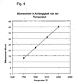
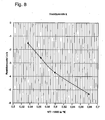
Die Erfinder haben experimentell gefunden, dass der Energieverbrauch pro Gewichtseinheit Etot mit steigender Temperatur zunächst abnimmt und durch ein Minimum geht, um bei noch höheren Temperaturen wieder anzusteigen. Die Temperatur, bei der der Energieverbrauch pro Gewichtseinheit Etot sein Minimum aufweist, wird im folgenden mit Teff bezeichnet.The inventors have experimentally found that the energy consumption per unit weight E tot initially decreases with increasing temperature and goes through a minimum rise again at even higher temperatures. The temperature at which the energy consumption per unit weight E tot has its minimum is referred to below as T eff .
Bei der Temperatur Teff gilt 
Die Bestimmung von Teff kann beispielsweise aus experimentellen Werten ermittelt werden, wie etwa anhand der Beispiele weiter unten erläutert ist.The determination of T eff can be determined, for example, from experimental values, as explained for example with reference to the examples below.
Dabei steht Etot für den gesamte Energieverbrauch pro Gewichtseinheit geschmolzenes.Glas und setzt sich zusammen aus der Nutzwärme pro Gewichtseinheit EN und dem Energieverlust pro Gewichtseinheit Ev.E tot stands for the total energy consumption per unit weight of molten glass and is made up of the useful heat per unit of weight E N and the energy loss per unit of weight E v .
Anstelle von Teff kann in erster Näherung auch die Temperatur ermittelt werden, bei der die Energieverlust pro Gewichtseinheit auf den Wert der Nutzwärme pro Gewichtseinheit abgefallen ist. Dementsprechend wird dazu die Temperatur ermittelt, bei der gilt: 
Vorzugsweise wird außerdem der Schmelze Wärmeenergie direkt zugeführt, beziehungsweise direkt in der Schmelze Energie in Wärmeenergie umgewandelt. Dies kann beispielsweise mittels entsprechender Einrichtungen durch direkte konduktive Beheizung und/oder durch direkte induktive Beheizung erfolgen.Preferably, the melt heat energy is also fed directly, or directly in the melt energy is converted into heat energy. This can be done, for example, by means of appropriate devices by direct conductive Heating and / or done by direct inductive heating.
Die in der Schmelze ablaufenden Prozesse sind von der absoluten Temperatur abhängig. Dementsprechend ist der Bereich Teff - 20% bis Teff + 20% insbesondere auf die absolute Temperatur bezogen.The processes taking place in the melt depend on the absolute temperature. Accordingly, the range T eff -20 % to T eff + 20% is particularly related to the absolute temperature.
Als relativer Durchsatz wird hier der Durchsatz D [Masse/Zeiteinheit] bezogen auf die Schmelzenmenge V * ρ im Schmelzaggregat verstanden, wobei V das Volumen und ρ die Dichte der Schmelze bezeichnen. Für den relativen Durchsatz Drel folgt damit: ![]()
![]()
Dabei bezeichnet t die mittlere Verweilzeit.In this case, t denotes the average residence time.
Der relative Durchsatz hat damit die Dimension einer reziproken Zeit.The relative throughput thus has the dimension of a reciprocal time.
Die erforderliche Verweilzeit wird durch das mit dem Verfahren zu erreichende Ergebnis bestimmt. Gemäß einer Ausführungsform der Erfindung wird mit dem Verfahren Gemenge eingeschmolzen so dass hier die erforderliche Verweilzeit dementsprechend die Einschmelzzeit umfasst.The required residence time is determined by the result to be achieved by the method. According to one embodiment of the invention, mixtures are melted down with the method so that here the required residence time accordingly includes the melting time.
Gemäß einer weiteren Ausführungsform wird mit dem Verfahren Schmelzgut geläutert, so dass die erforderliche Verweilzeit die für das Läutern notwendige Zeit umfasst. Auch kann in einem Aggregat mit gekühlten Wänden sowohl eingeschmolzen, als auch geläutert werden. Dabei umfasst entsprechend die erforderliche Verweilzeit die für das Einschmelzen und Läutern notwendige Zeit. Unter der erforderlichen Verweilzeit wird außerdem die mittlere Verweilzeit des Schmelzguts im Schmelzaggregat verstanden.According to a further embodiment, the process melts the material to be melted, so that the required residence time comprises the time necessary for the refining. Also can be melted in an aggregate with cooled walls, as well as be purified. It accordingly includes the required residence time necessary for the melting and refining time. The required residence time is also understood to mean the average residence time of the melt in the melt aggregate.
Der Bereich von Teff - 20% bis Teff + 20% erweist sich als besonders günstig für den Energieverbrauch pro Gewichtseinheit des Schmelzguts.The range from T eff - 20% to T eff + 20% proves to be particularly favorable for the energy consumption per unit weight of the melt.
Bei sehr hohen Durchsätzen bzw. sehr kurzen Aufenthaltszeiten der Schmelze im Schmelzaggregat spielen nicht nur die physikalischen Prozesse, wie beispielsweise die Aufstiegsgeschwindigkeit der Blasen bei der Läuterung eine Rolle, sondern auch die chemischen Reaktionen, insbesondere die Kinetik, mit der sich die thermodynamischen Gleichgewichte in der Schmelze einstellen. Durch die Temperaturerhöhung der Glasschmelze wird neben den physikalischen Prozessen, zum Beispiel der Blasenaufstiegsgeschwindigkeit, auch die Kinetik der Einstellung der thermodynamischen Gleichgewichte, beispielsweise durch die höhere Diffusionsgeschwindigkeit der Gase zu den Läuterblasen erhöht. Die Beschleunigung der Kinetik erlaubt bei hohen Temperaturen eine ausreichend hohe Durchsatzsteigerung, so dass der erhöhte Energieverlust pro Gewichtseinheit bei höheren Temperaturen durch die angepasste Durchsatzsteigerung mehr als ausgeglichen wird. Dazu ist ein Heizverfahren erforderlich, welches der Schmelze ausreichend Heizenergie zuführen kann, um zumindest einen Bereich der Schmelze trotz der Kühlung der Wände auf die vorgesehene Temperatur bringen zu können.With very high throughputs or very short residence times of the melt in the smelting unit, not only the physical processes, such as, for example, the rate of ascent of the bubbles during refining play a role, but also the chemical reactions, in particular the kinetics, with which the thermodynamic equilibria in the melt Adjust melt. By increasing the temperature of the molten glass, in addition to the physical processes, for example the bubble ascent rate, the kinetics of the adjustment of the thermodynamic equilibria, for example due to the higher diffusion rate of the gases to the lautering bubbles, are increased. The acceleration of the kinetics allows a sufficiently high throughput increase at high temperatures, so that the increased energy loss per unit weight at higher temperatures is more than compensated for by the adjusted throughput increase. For this purpose, a heating method is required, which can supply sufficient heat energy to the melt in order to bring at least a portion of the melt despite the cooling of the walls to the intended temperature can.
Im folgenden wird das Verfahren anhand einer etwas vereinfachenden Betrachtung näher erläutert. Zur Verdeutlichung sind zu einigen Größen dabei in eckigen Klammern Einheiten angegeben, wobei beispielhaft für das Gewicht die Einheit Kilogramm [kg], für die Zeit die Einheit Stunden [h], für die Leistung die Einheit Kilowatt [kW] und für die Energie Kilowattstunden [kWh] gewählt wurden.In the following, the method is explained in more detail with reference to a somewhat simplistic view. For clarity, units are given in square brackets for some quantities, with the unit being kilograms [kg], the unit hours [h] for the time, the units kilowatts [kW] for the power and kilowatt hours for the energy [ kWh] were selected.
Die Erfinder fanden heraus, dass bei korrekter und erweiterter Betrachtung eine energiesparende Schmelze in Aggregaten mit gekühlten Wänden möglich ist, wenn beim Schmelzen von Gläsern zwischen Nutzwärme einerseits und Energieverlust andererseits unterschieden wird. Der gesamte Energieverbrauch pro Gewichtseinheit geschmolzenes Glas Etot setzt sich zusammen aus der Nutzwärme pro Gewichtseinheit EN und dem Energieverlust pro Gewichtseinheit Ev. 
Als Nutzwärme pro Gewichtseinheit, En, wird die Wärmemenge pro Gewichtseinheit geschmolzenem Glas bezeichnet, die einem Glasgemenge und/oder Scherben zum Aufheizen und Aufschmelzen zugeführt werden muss.
Die Nutzwärme pro Gewichtseinheit umfasst:
- die Wärmemenge pro Gewichtseinheit zum Aufheizen des Gemenges und/oder der Scherben: EN1 = cp1 * ΔT1, wobei ΔT1 die Temperaturdifferenz zwischen der Ausgangstemperatur bis zur Schmelz- oder Übergangstemperatur bezeichnet,
- die latente Wärme pro Gewichtseinheit: EN2 = ΔH, sowie
- die Wärmemenge pro Gewichtseinheit zum Aufheizen der Glasschmelze auf die gewünschte Prozeßtemperatur: EN3 = cp2 * ΔT2. Dabei bezeichnet ΔT2 die Temperaturdifferenz von der Schmelz- oder Übergangstemperatur bis zur gewählten Prozeßtemperatur, die erfindungsgemäß in zumindest einem Bereich der Schmelze in einem Bereich von Teff -20% bis Teff +20% legt.
The useful heat per unit of weight includes:
- the quantity of heat per unit of weight for heating the mixture and / or the shards: E N1 = c p1 * ΔT 1 , where ΔT 1 denotes the temperature difference between the starting temperature and the melting or transition temperature,
- the latent heat per unit weight: E N2 = ΔH, as well
- the amount of heat per unit of weight for heating the molten glass to the desired process temperature: E N3 = c p2 * ΔT 2 . In this case, ΔT 2 denotes the temperature difference from the melting or transition temperature to the selected process temperature, which according to the invention in at least one region of the melt in a range of T eff -20% to T eff + 20%.
Die latente Wärme ΔH umfaßt die Reaktions- und/oder Phasenübergangswärme beim Aufschmelzen oder beim Glasübergang des Schmelzguts, welches beispielsweise in Form von Gemenge und/oder Scherben zugegeben wird.The latent heat .DELTA.H comprises the reaction and / or phase transition heat during melting or glass transition of the melt, which is added for example in the form of mixtures and / or shards.
Für eine erste Näherung kann die spezifische Wärmekapazität des Schmelzguts unterhalb der Schmelz- oder Übergangstemperatur cp1 und die spezifische Wärmekapazität des Schmelzguts oberhalb der Schmelz- oder Übergangstemperatur, cp2 gleichgesetzt werden, so daß gilt: 
Für EN ergibt, sich dann: ![]()
![]()
Die Nutzwärme, insbesondere die benötigte Nutzwärme für das Läutern, ist somit direkt proportional zum Durchsatz und der Schmelztemperatur. Die Nutzwärme pro kg geschmolzenes Glas EN ist unabhängig von der Schmelzzeit und dem Schmelzverfahren.The useful heat, in particular the required useful heat for the refining, is thus directly proportional to the throughput and the melting temperature. The useful heat per kg of molten glass E N is independent of the melting time and the melting process.
Vom Schmelzverfahren abhängig ist dagegen der Energieverlust.On the other hand, the energy loss depends on the melting process.
Ein Energieverlust findet vor allem statt durch:
- die Wärmeabstrahlung an der Glasoberfläche
- die Wärmeableitung durch die Wände und den Boden des Schmelzgefäßes, und
- die Wärmeableitung der heißen Gase bei vorhandener Gas- oder Ölbeheizung.
In der vereinfachten Betrachtung wird unter anderem der Beitrag der Wärmeabstrahlung zum Energieverlust nicht berücksichtigt.
Der Energieverlust pro Zeit gibt an, welche Wärmemenge pro Zeiteinheit kWh/h verloren geht. Beim Energieverlust pro Zeit handelt es sich somit um eine Energieverlustleistung kWh/h = kW.
Der Energieverlust pro Gewichtseinheit gibt unter Berücksichtigung des Durchsatzes an, welche Wärmemenge pro Gewichtseinheit Ev verloren geht.
Der.Energieverlust, bzw. der Energieverlust pro Gewichtseinheit sind vom jeweiligen Schmelzaggregat abhängig.
Der Energieverlust durch die Abstrahlung aus der Glasoberfläche hängt zum einen davon ab, ob die Oberfläche frei ist, oder ob die Oberfläche durch einen Gemengeteppich oder Blasenteppich abgedeckt ist. Die Wärmeabstrahlung an der Glasoberfläche wird deutlich geringer, wenn die Oberfläche der Glasschmelze mit einem Gemengeteppich oder Blasenteppich abgedeckt ist. Zum anderen wird die von der Glasoberfläche abgestrahlte Wärme von dem Gewölbe der Schmelzwannen wieder reflektiert. Der Wärmeverlust durch die Oberfläche entsteht durch den Wärmeverlust durch die Wand des Gewölbes.
Bei konventionellen Wannen und bei Schmelzaggregaten mit gekühlten Wänden und einer Hochfrequenz- oder konduktiven Beheizung ist der Energieverlust pro Flächeneinheit durch die Wärmeabstrahlung an der Oberfläche bei gleicher Temperatur und Oberflächenabdeckung im wesentlichen gleich.
Bei Gas- oder Ölbefeuerung kommt bei konventionellen Wannen noch der Wärmeverlust durch das heiße ausströmende Gas hinzu.
Im Gegensatz zu den konventionellen Wannen, bei denen die obere Schmelztemperatur durch den Wannenangriff begrenzt wird, ist beim Schmelzen in Schmelzaggregaten mit gekühlten Wände die Schmelztemperatur durch den Wannenangriff im wesentlichen nicht eingeschränkt.
Die Erfinder fanden überraschend heraus, dass bei einem Schmelzaggregat mit gekühlten Wänden wie zum Beispiel einem Skulltiegel, entgegen der bestehenden Meinung, bei Erhöhung der Schmelztemperatur trotz dem erhöhten Energieverlust durch die Wand und den ,Boden und der höheren Nutzenergie zum Aufheizen der Schmelze der Energieverbrauch pro Gewichtseinheit abgesenkt werden kann, wenn die Aufenthaltszeit der Schmelze im Schmelzaggregat entsprechend der erhöhten Reaktionsgeschwindigkeit verkürzt wird.
Der Energieverlust durch die Wand und den Boden ist abhängig von dem Wärmedurchgang k [kW/cm2*K], der Temperatur der Schmelze [T] und der gekühlten Wandfläche F [cm2] des Schmelzaggregates.
Bei den Schmelzaggregaten ändert sich das Oberflächen- zu Volumen-Verhältnis der Schmelze mit ihrem Volumen. Dieses Verhältnis wird im folgenden mit F0 bezeichnet, wobei die maßgebliche Oberfläche im wesentlichen die Oberfläche der Schmelze darstellt, welche in Kontakt mit den gekühlten Wänden des Schmelaggregats ist.
Anstelle der Fläche F kann somit auch der Flächen/Volumen-Faktor F0 mal dem Schmelzvolumen V eingesetzt werden.
Für den Energieverlust durch die Wände, Ev, kann vereinfacht angesetzt werden
Der Energieverlust pro Gewichtseinheit Ev ist bei einem vorgegebenen Schmelzvolumen zusätzlich abhängig vom Durchsatz D ( kg/h ), so dass sich für Ev ergibt:

Der Durchsatz D der Schmelze, beziehungsweise der relative Durchsatz Drel wird durch die Aufenthaltszeit t der Schmelze im Volumen V des Schmelzaggregates bestimmt.

- the heat radiation at the glass surface
- the heat dissipation through the walls and bottom of the melting vessel, and
- the heat dissipation of the hot gases in the presence of gas or oil heating.
In the simplified consideration, among other things the contribution of the heat radiation to the energy loss is not considered.
The energy loss per time indicates which amount of heat per unit of time kWh / h is lost. The energy loss per time is therefore an energy loss kWh / h = kW.
The energy loss per unit weight indicates, taking into account the throughput, which amount of heat per unit weight E v is lost.
Der.Energieverlust, or the energy loss per unit weight are dependent on the particular smelting unit.
The loss of energy due to radiation from the glass surface depends, on the one hand, on whether the surface is free or whether the surface is covered by a carpet of mats or bubble blanket. The heat radiation at the glass surface is significantly reduced if the surface of the glass melt is covered with a carpet or bubble carpet carpet. On the other hand, the heat radiated from the glass surface is reflected by the vault of the melting tank again. The heat loss through the surface is caused by the loss of heat through the wall of the vault.
For conventional wells and chill-walled heaters with high frequency or conductive heating, the energy loss per unit area is substantially the same due to surface heat radiation at the same temperature and surface coverage.
With gas or oil firing, the heat loss due to the hot gas flowing out of conventional tanks is added.
In contrast to the conventional tubs, where the upper melting temperature is limited by the tub attack, when melting in cooling units with cooled walls, the melting temperature is not substantially limited by the tub attack.
The inventors have surprisingly found that in a melting aggregate with cooled walls such as a skull crucible, contrary to the existing opinion, increasing the melting temperature despite the increased energy loss through the wall and the bottom and the higher useful energy for heating the melt energy consumption per Weight unit can be lowered when the residence time of the melt in the melting unit is shortened according to the increased reaction rate.
The energy loss through the wall and the floor depends on the heat transfer k [kW / cm 2 * K], the temperature of the melt [T] and the cooled wall surface F [cm 2 ] of the melter.
In the melting aggregates, the surface to volume ratio of the melt changes with its volume. This Ratio is hereinafter referred to as F 0 , wherein the relevant surface is substantially the surface of the melt, which is in contact with the cooled walls of the melter.
Instead of the area F, the area / volume factor F 0 can thus also be used for the melt volume V.
For the energy loss through the walls, E v , can be simplified
The energy loss per unit weight E v is additionally dependent on the throughput D (kg / h) for a given melt volume, so that for E v :
The throughput D of the melt, or the relative throughput D rel is determined by the residence time t of the melt in the volume V of the melting unit.
Daraus ergibt sich für Ev : ![]()
![]()
![]()
![]()
![]()
![]()
Die erforderliche Verweilzeit τ der Schmelze im Schmelzaggregat V ist abhängig'von der jeweiligen Reaktionsgeschwindigkeit zum Beispiel der Auflösungsgeschwindigkeit des Gemenges oder der Aufstiegsgeschwindigkeit der Läuterblasen. Für τ kann vereinfachend mit einer Konstanten E, die einer charakteristischen Aktivierungstemperatur entspricht, angesetzt werden: 
Dabei bezeichnet τ0 die erforderliche Verweilzeit bei einer Referenztemperatur T0. Hieraus ergibt sich Ev, wenn die erforderliche Verweilzeit τ an die mittlere Verweilzeit t, beziehungsweise den relativen Durchsatz Drel=1/t angepaßt wird, so daß dementsprechend t=τ gilt, zu: 
Der Energieverbrauch pro Gewichtseinheit Etot des Schmelzguts ist zunächst abhängig von der Verweilzeit des Schmelzguts im Schmelzaggregat. Weiterhin ist die erforderliche Verweilzeit temperaturabhängig. So verläuft beispielsweise das Läutern bei hohen Temperaturen schneller und die Verweilzeit, die erforderlich ist, um das gewünschte Ergebnis, etwa eine geläuterte Schmelze zu erhalten, wird verkürzt.The energy consumption per unit weight E tot of the melt is initially dependent on the residence time of the melt in the melting unit. Furthermore, the required residence time is temperature dependent. For example, refining at high temperatures is faster and the residence time required to achieve the desired result, such as a refining melt, is shortened.
Die Erfinder haben überraschend erkannt, dass die Erhöhung der Schmelztemperatur und die damit verbundene schnellere Reaktionsgeschwindigkeit in der Schmelze einen mit steigender Temperatur sinkenden Energiebeitrag Etot ergibt, obwohl mehr Energie zur Kühlung der Wände des Schmelzaggregates und zum Aufheizen der Schmelze eingesetzt werden muss.The inventors have surprisingly recognized that the increase of the melting temperature and the associated faster reaction rate in the melt results in a decreasing energy contribution E tot with increasing temperature, although more energy must be used to cool the walls of the melting unit and to heat the melt.
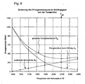
Die Änderung des Energieverbrauchs pro Gewichtseinheit Etot mit der Temperatur ist gleich der Änderung der Nutzwärme pro Gewichtseinheit EN mit der Temperatur plus der Änderung des Energieverlustes pro Gewichtseinheit Ev mit der Temperatur. ![]()
![]()
Die Änderung der Nutzwärme pro Gewichtseinheit mit der Temperatur dEN/dT ist für das Aufheizen der Schmelze konstant und definitionsgemäß gleich cp.The change in the useful heat per unit weight with the temperature dE N / dT is constant for the heating of the melt and by definition equal to c p .
Die Nutzwärme pro Gewichtseinheit steigt mit der Temperatur linear an: ![]()

![]()
Das bedeutet, dass zum Erreichen einer höheren Temperatur mehr Nutzwärme pro Gewichtseinheit zum Aufheizen der Schmelze erforderlich ist.This means that to achieve a higher temperature more useful heat per unit weight is required to heat the melt.
Für die Temperaturabhängigkeit des Energieverlustes pro Gewichtseinheit gilt: ![]()

![]()
Die Erfinder haben überraschend gefunden, dass der Wärmedurchgang k zwischen 1700 °C und 2400 °C bei Vorhandensein einer Skullschicht nur linear ansteigt und somit d(k*T)/dT gleich k ist. Somit ergibt sich für dEv/dT: 
Weiterhin haben die Erfinder experimentell herausgefunden, dass dEv/dT mit steigender Temperatur abnimmt.
Die Ursache hierfür ist die starke Zunahme der Reaktionsgeschwindigkeit mit der Temperatur und damit verbunden die starke Abnahme der benötigten, beziehungsweise erforderlichen Verweilzeit τ der Schmelze im Schmelzaggregat.Furthermore, the inventors have experimentally found that dE v / dT decreases with increasing temperature.
The reason for this is the strong increase in the reaction rate with the temperature and, associated therewith, the strong decrease in the required or required residence time τ of the melt in the melting unit.
Der Anstieg von EN mit der Temperatur und die Abnahme von Ev mit der Temperatur führen dazu, dass bei einer Temperatur Teff ein Optimum erreicht wird, bei welchem der Energieverbrauch pro Gewichtseinheit Etot minimal wird. 
Die Einrichtung zur konduktiven Beheizung der Schmelze umfasst gemäß einer Ausführungsform der Erfindung gekühlte Elektroden. Durch den Einsatz derartiger gekühlter Elektroden kann die Schmelze auf hohe Temperaturen aufgeheizt werden, welche auch die Anwendungsgrenztemperaturen der geeigneten Elektrodenmaterialien überschreiten, so dass eine für einen niedrigen Energieverbrauch günstige Temperatur eingestellt werden kann. Solche Elektroden und Schmelzaggregate zur direkten konduktiven Beheizung von Schmelzen werden auch in den beiden früheren deutschen Anmeldungen mit den Anmeldenummern
Die vorzugsweise großflächigen Elektroden können mit Vorteil in Aussparungen gekühlter Wände des Aggregats eingesetzt sein.The preferably large-area electrodes can be used with advantage in recesses of cooled walls of the unit.
Die Schmelze kann mit Hilfe der gekühlten Elektroden mit Wechselstrom von 50 Hz bis 50 kHz vorzugsweise von 2 kHz bis 10 kHz beheizt werden. Die Elektrodenflächen können vorteilhaft so groß dimensioniert werden, dass die Stromdichte zur Beheizung der Schmelze an keiner Stelle der Elektroden mehr als 5 A/cm2 aufweist. Gemäß einer bevorzugten Weiterbildung dieser Ausführungsform weisen die Elektroden mindestens einen, vorzugsweise zwei Kühlkreise über die deren Kühlung geregelt werden kann. Als Kühlmedium können vorzugsweise Luft und Wasser dienen.The melt can be heated with the aid of the cooled electrodes with alternating current of 50 Hz to 50 kHz, preferably from 2 kHz to 10 kHz. The electrode surfaces can advantageously be dimensioned so large that the current density for heating the melt at any point of the electrodes has more than 5 A / cm 2 . According to a preferred development of this embodiment, the electrodes have at least one, preferably two cooling circuits via which their cooling can be regulated. As a cooling medium may preferably serve air and water.
Ein Schmelzaggregat mit konduktiver Beheizung, beziehungsweise eine Weiterbildung des erfindungsgemäßen Verfahrens mit konduktiver Beheizung sind auch noch für Schmelzen geeignet, deren elektrische Leitfähigkeit kleiner als 10-1 Ω-1cm-1 ist, beispielsweise für Schmelzen mit einer elektrischen Leitfähigkeit im Bereich von 10-3 Ω-1cm-1 beziehungsweise vorzugsweise von 10-2 Ω-1cm-1 bis 10-1 Ω-1cm-1 A fusing unit with conductive heating, or a development of the method according to the invention with conductive heating are also suitable for melts whose electrical conductivity is less than 10 -1 Ω -1 cm -1 , for example, for melts having an electrical conductivity in the range of 10 -. 3 Ω -1 cm -1 or preferably from 10 -2 Ω -1 cm -1 to 10 -1 Ω -1 cm -1
Um Schmelzen in Schmelzaggregaten mit gekühlten Wänden auf Temperaturen über 1600 °C bis hin zu Teff aufheizen zu können, ist es nötig, dass die gekühlten Elektroden direkt in die gekühlten Wände des Schmelzaggregates eingebaut werden.In order to heat melts in cooling units with cooled walls to temperatures above 1600 ° C up to T eff , it is necessary that the cooled electrodes are installed directly in the cooled walls of the melter.
Erfindungsgemäß enthalten die großflächigen Elektroden, die ein Bestandteil der gekühlten Wände sind, mindestens ein regelbares Kühlsystem. Vorzugsweise enthalten die Elektroden ein doppeltes regelbares Kühlsystem z.B. eins für eine Gaskühlung und eins für eine Flüssigkeitskühlung.
Die großflächigen gekühlten Elektroden können sowohl in die Wände von Skulltiegeln als auch in gekühlte keramische Wände eingebaut werden.According to the invention, the large-area electrodes, which are a component of the cooled walls, contain at least one controllable cooling system. The electrodes preferably contain a double controllable cooling system, for example one for gas cooling and one for liquid cooling.
The large-area cooled electrodes can be installed both in the walls of skull crucibles and in cooled ceramic walls.
Es hat sich gezeigt, dass auch bei den Schmelzaggregaten mit gekühlten Wänden, die direkt konduktiv mit Wechselstrom beheizt werden, bei Erhöhung der Schmelztemperatur der Anstieg des Energieeintrages durch die Erhöhung der elektrischen Leitfähigkeit größer ist, als der Anstieg des Wärmeverlustes durch die gekühlten Wände und die Erhöhung der Nutzwärme zu Erhöhung der Schmelztemperatur.It has been shown that even with the cooling units with cooled walls, which are directly conductively heated with alternating current, the increase in the energy input by increasing the electrical conductivity is greater than the increase in heat loss through the cooled walls and the Increase the useful heat to increase the melting temperature.
Die Einrichtung zur Hochfrequenzbeheizung der Schmelze in einem Schmelzaggregat mit gekühlten Wänden umfasst gemäß einer Ausführungsform der Erfindung einen Skulltiegel, der mit einer Hochfrequenzspule umgeben ist. Der Skulltiegel wird aus gekühlten Metallrohren gebildet. Zwischen den Metallrohren befinden sich Spalten, wodurch eine direkte Einkopplung der Hochfrequenz in die Glasschmelze möglich ist.The device for high-frequency heating of the melt in a cooling unit with cooled walls comprises, according to an embodiment of the invention, a skull crucible which is surrounded by a radio-frequency coil. The skull crucible is made of cooled metal tubes. There are gaps between the metal tubes, allowing direct coupling of the high frequency into the molten glass.
Mit Hochfrequenz beheizte Skulltiegel sind beispielsweise in den Patentschriften
Das Verfahren wird ferner besonders bevorzugt als kontinuierliches Verfahren durchgeführt, wobei der Schmelze mittels entsprechender Einrichtungen kontinuierlich Schmelzgut zugeführt und entnommen wird. Das zugeführte Schmelzgut kann dabei sowohl in fester Form als Gemenge, als auch bereits als Schmelze zugeführt werden. Die Entnahme von Schmelzgut erfolgt vorzugsweise in geschmolzener Form.The method is also particularly preferably carried out as a continuous process, wherein the melt is supplied by means of appropriate facilities continuously melt and removed. The supplied melt can be supplied both in solid form as a mixture, as well as already as a melt. The removal of molten material is preferably carried out in molten form.
Die Erfinder haben erkannt, dass sich die Nachteile, die bei der Temperaturerhöhung bei konventionellen Wannen aufgrund des chemischen Angriffs des Wannenmaterials auftreten, beim Schmelzen in Aggregaten mit gekühlten Wänden vermeiden lassen. Die Wände des Schmelzaggregats müssen soweit abgekühlt werden können, dass keine Korrosion der Wände mehr erfolgt, auch bei sehr hoher Konvektion der Glasschmelze.The inventors have recognized that the disadvantages associated with the increase in temperature in conventional tubs due to the chemical attack of the tub material can be avoided when melting in aggregates with cooled walls. The walls of the melting unit must be able to be cooled down to such an extent that corrosion of the walls no longer takes place, even with very high convection of the molten glass.
Beim Schmelzen in einem Schmelzaggregat mit gekühlten Wänden sind dann der Temperaturerhöhung in bezug auf die Wände kaum Grenzen gesetzt.When melting in a melting unit with cooled walls then the temperature increase with respect to the walls are virtually unlimited.
Die Erfinder haben weiterhin erkannt, dass es sich, bei Schmelzaggregaten mit gekühlten Wänden lohnt, die Schmelze nicht nur auf die Temperatur Tkon ,die für den Einschmelz- oder Läuterprozess gerade nötig ist, zu erhitzen, sondern auf eine deutlich höhere Temperatur, und den Durchsatz entsprechend der kürzeren erforderlichen Verweilzeit zu erhöhen. Gemäß einer Ausführungsform der Erfindung ist dabei vorgesehen, zumindest ein Bereich der Schmelze auf mehr als 1700° C zu erhitzen.The inventors have further recognized that it is worthwhile in melt aggregates with cooled walls, the melt not only to the temperature T kon , which is just needed for the melting or refining process, but to a much higher temperature, and the To increase throughput according to the shorter required residence time. According to one embodiment of the invention, it is provided to heat at least a portion of the melt to more than 1700 ° C.
Obwohl der Energieverlust bei einem Tiegel mit gekühlten Wänden, wie beispielsweise bei einem Skulltiegel bei Temperaturerhöhung ansteigt, wurde überraschenderweise gefunden, dass dieser Anstieg bei Erhöhung der Schmelztemperaturen langsamer ist, als der Anstieg der Energie-, beziehungsweise Leistungseinsparung durch Durchsatzerhöhung.Although the energy loss in a crucible with cooled walls, such as a skull crucible increases with temperature increase, it was surprisingly found that this increase is slower with increasing melting temperatures, than the increase in energy, or power savings throughput increase.
Die chemischen Reaktionen und die physikalischen Prozesse beim Einschmelzen und Läutern weisen vielfach eine exponentielle Abhängigkeit der Prozessgeschwindigkeit von der Temperatur auf, während die Temperaturabhängigkeit der Wärmeabfuhr durch die gekühlten Wände im wesentlichen nur von der Wandoberfläche des Schmelzschmelzaggregates und der Temperaturdifferenz abhängen und mit steigender Temperatur überraschenderweise vergleichsweise langsam anwachsen.The chemical reactions and the physical processes during melting and refining often exhibit an exponential dependence of the process speed on the temperature, while the temperature dependence of the heat dissipation through the cooled walls essentially depends only on the wall surface of the melt melter and the temperature difference and surprisingly comparatively with increasing temperature grow slowly.
Die Erfinder haben erkannt, dass durch die Temperaturerhöhung der Schmelze über Tkon hinaus die physikalischen Prozesse und chemische Reaktionen im Schmelzaggregat so stark beschleunigt werden, dass es möglich ist, den Durchsatz pro Volumeneinheit in einem Schmelzaggregat mit gekühlten Wänden so weit zu erhöhen, dass mit Zunahme der Schmelztemperatur T eine Abnahme des Energieverlustes pro Gewichtseinheit Ev erfolgt, das heißt, dass der Energiegewinn bzw. die Verringerung des Energieverlusts durch die Durchsatzsteigerung deutlich größer ist, als der zusätzlichen Energieverbrauch, der für die Temperaturerhöhung der Schmelze und das Halten der Schmelze im Schmelzaggregat bei der höheren Temperatur benötigt wird.The inventors have recognized that by increasing the temperature of the melt beyond T.sub.con , the physical processes and chemical reactions in the smelting unit are accelerated to such an extent that it is possible to increase the throughput per unit volume in a cooling unit with cooled walls to such an extent Increase of the melting temperature T is a decrease in energy loss per unit weight E v , that is, the energy gain or the reduction of energy loss through the increase in throughput is significantly greater than the additional energy consumption, the temperature increase of the melt and holding the melt in the Melting unit at the higher temperature is needed.
Durch die Erhöhung des Durchsatzes mit steigender Temperatur, über Tkon hinaus, nimmt der Energieverlust pro Gewichtseinheit Ev stetig bis zur Temperatur Teff ab.By increasing the throughput with increasing temperature, beyond T kon addition, the energy loss per unit weight E v steadily decreases up to the temperature T eff .
Der Energieverbrauch pro Gewichtseinheit Etot, also die Summe aus Energieverlust pro Gewichtseinheit Ev insbesondere durch die Wände und den Boden und der Nutzwärme pro Gewichtseinheit EN zum Aufheizen der Schmelze durchläuft, wie oben bereits erläutert, ein Minimum bei Teff, sofern der Durchsatz an die erforderliche Verweilzeit t angepasst wird.The energy consumption per unit weight E tot , ie the sum of energy loss per unit weight E v, in particular through the walls and the floor and the useful heat per unit weight E N for heating the melt, as explained above, passes through a minimum at T eff , provided the throughput is adapted to the required residence time t.
Wird das Minimum zu höheren Temperaturen hin überschritten, so steigt der Energieverbrauch pro Gewichtseinheit Etot als Funktion der Temperatur jedoch nur sehr langsam wieder an, während unterhalb des Minimums bei niedrigeren Temperaturen ein starker Abfall von Etot zu Teff hin als Funktion der Temperatur erfolgt.However, if the minimum is exceeded towards higher temperatures, the energy consumption per unit of weight E tot increases only very slowly as a function of temperature, while below the minimum at lower temperatures there is a sharp decrease from E tot to T eff as a function of temperature ,
Dementsprechend ist der Effekt der Energieeinsparung mit steigender Temperatur im Bereich unterhalb von Teff sehr groß.Accordingly, the effect of energy saving with increasing temperature in the range below T eff is very high.
Auch oberhalb von Teff kann ein Betrieb eines Aggregates vorteilhaft sein, etwa, um bei, aufgrund des langsamen Anstiegs des Energieverbrauchs in diesem Bereich nur geringfügig erhöhten Energiekosten sehr schnell mit hohem Durchsatz arbeiten zu können. Allerdings ist hierbei auch der apparative Aufwand größer. Daher wird ein Betrieb bei einer Temperatur unterhalb oder bis zu Teff, also in einem Bereich von Teff - 20% bis Teff bevorzugt. Auch kann es sein, dass die angestrebte Temperatur Teff nicht erreicht werden kann. Dies hängt unter anderem von der Zusammensetzung der Schmelze ab. Wenn die Schmelze Bestandteile enthält, die unterhalb von Teff bereits beginnen zu verdampfen, dann kann die Schmelze nur bis zur Verdampfungstemperatur Tverd des betreffenden Bestandteils der Schmelze erhitzt werden, ohne die'gewünschte Zusammensetzung des erschmolzenen Glases stark zu verändern. Ist dann Tverd kleiner als Teff, so kann nur ein Teil des maximal möglichen Energieeinsparungspotentials verwirklicht werden. Die Temperatur Teff kann auch dann nicht erreicht werden, wenn es nicht möglich ist, dem System genügend Wärmeenergie zuzuführen.Even above T eff , operation of an aggregate may be advantageous, for example, to be able to work very quickly with high throughput due to the only slight increase in energy costs due to the slow increase in energy consumption in this area. However, in this case, the equipment cost is greater. Therefore, operation at a temperature below or up to T eff , that is, in a range of T eff -20 % to T eff, is preferred. It may also be that the desired temperature T eff can not be achieved. This depends inter alia on the composition of the melt. When the melt contains constituents below T eff already begin to evaporate, then the melt can be heated only to the evaporation temperature T verd of the relevant component of the melt, without changing the'gewünschte composition of the molten glass strong. If T verd is smaller than T eff then only a part of the maximum possible energy saving potential can be realized. The temperature T eff can not be achieved even if it is not possible to supply sufficient heat energy to the system.
Das Maximum der Energieeinsparung ist in vielen Fällen in erster Näherung bei einer Temperatur erreicht, bei der die Nutzwärme pro Gewichtseinheit EN zur Erhöhung der Schmelztemperatur gleich dem Energieverlust pro Gewichtseinheit Ev ist.The maximum energy saving is achieved in many cases in a first approximation at a temperature at which the useful heat per unit weight E N to increase the melting temperature is equal to the energy loss per unit weight E v .
Gemäß einer Ausführungsform der Erfindung kann daher eine Temperatur kleiner oder gleich dieser Temperatur gewählt werden, bei welcher die Nutzwärme pro Gewichtseinheit und der Energieverlust prp Gewichtseinheit gleich groß sind. ![]()
![]()
Da der Abfall des Energieverlusts pro Gewichtseinheit mit der Temperatur steiler ist als der Anstieg der Nutzwärme pro Gewichtseinheit liegt das Maximum der Energieeinsparung etwas oberhalb der Temperatur bei der die Nutzwärme pro Gewichtseinheit En gleich dem Energieverlust pro Gewichtseinheit Ev ist.Since the drop in energy loss per unit weight with temperature is steeper than the increase in useful heat per unit weight, the maximum of energy savings is slightly above the temperature at which the useful heat per unit weight E n equals the energy loss per unit weight E v .
Zur Bestimmung der Temperatur Teff werden
- die Nutzwärme pro Gewichtseinheit zum Aufheizen der Schmelze,
- der Energieverlust der Anlage bzw. der Wärmeverlust, durch die Wände und den Boden, sowie
- die Durchsatzsteigerung
- the useful heat per unit weight for heating the melt,
- the energy loss of the plant or the heat loss, through the walls and the floor, as well
- the throughput increase
Die Änderung der Nutzwärme pro Gewichtseinheit zum Aufheizen einer Glasschmelze mit der Temperatur kann, wie bereits erwähnt, aus der spezifischen Wärme Cp der Glasschmelze bestimmt werden.The change in the useful heat per unit weight for heating a glass melt with the temperature can, as already mentioned, be determined from the specific heat C p of the glass melt.
Die spezifische Wärmekapazität cp von Glasschmelzen liegt zwischen 1 und 2 kJ /(kg * K), beispielsweise bei 1,175 kJ /(kg * K) für Kalk-Natron-Glas und 1,5 kJ /(kg * K) für ein Alumino-Silicat-Glas zur Herstellung von Glaskeramik.The specific heat capacity c p of glass melts is between 1 and 2 kJ / (kg * K), for example 1.175 kJ / (kg * K) for soda-lime glass and 1.5 kJ / (kg * K) for an alumino -Silicate glass for the production of glass ceramics.
Die Änderung des Energieverlust der Wand in Abhängigkeit von der Temperatur kann beispielsweise direkt durch Messung der Temperatur der Kühlflüssigkeit, die zur Kühlung der Wände eingesetzt wird, in Abhängigkeit von der Temperatur gemessen werden.The change in the energy loss of the wall as a function of the temperature can be measured, for example, directly by measuring the temperature of the cooling liquid used to cool the walls as a function of the temperature.
Die Änderung des Durchsatzes mit der Temperatur hängt von der jeweils benötigten Aufenthaltszeit t der Schmelze im Schmelzvolumen ab. Die Änderung des Durchsatzes mit der Temperatur kann entweder experimentell direkt bestimmt werden oder über die Änderung der Reaktionsgeschwindigkeit mit der Temperatur.The change of the throughput with the temperature depends on the respectively required residence time t of the melt in the melt volume. The change in throughput with temperature can be determined either experimentally directly or by changing the reaction rate with temperature.
Um den relativen Durchsatz von Schmelzgut an die erforderliche Verweilzeit t in der Schmelze anzupassen, kann einerseits der absolute Mengendurchsatz angepasst werden, oder andererseits kann auch ein gewünschter absoluter Mengendurchsatz beibehalten werden und das Schmelzenvolumen bzw. die Abmessungen des Aggregats angepasst werden. Dies ist beispielsweise dann von Vorteil, wenn das Aggregat Teil einer Produktionsstrecke mit vorgegebenem Mengendurchsatz ist.To adjust the relative throughput of melt to the required residence time t in the melt, on the one hand, the absolute mass flow rate can be adjusted, or on the other hand, a desired absolute Mass flow rate can be maintained and the melt volume or the dimensions of the unit to be adjusted. This is for example advantageous if the unit is part of a production line with a given mass flow rate.
Aus dem Durchsatz bei der Temperatur Teff lässt sich die Größe des Schmelzaggregates für den vorgegebenen Durchsatz bestimmen.From the throughput at the temperature T eff , the size of the melting unit can be determined for the given throughput.
Erfolgt bei Teff anstelle einer Durchsatzerhöhung eine Verkleinerung des Schmelzaggregates, dann erhöht sich der Energieverlust pro Gewichtseinheit und damit auch der Energieverbrauch pro Gewichtseinheit etwas, da der Flächenfaktor F0 sich etwas erhöht.If at T eff instead of an increase in throughput a reduction of the smelting unit, then the energy loss per unit weight and thus the energy consumption per unit weight increases slightly, since the area factor F 0 increases slightly.
Selbstverständlich können auch der absolute Durchsatz und das Aggregat zusammen angepasst werden.Of course, the absolute throughput and the aggregate can be adjusted together.
Die Erhöhung des Durchsatzes oder die Verkleinerung der Schmelzaggregate,mit gekühlten Wänden kann jedoch nur so weit erfolgen, dass die Verweilzeit t der Schmelze in dem Schmelzaggregat mit gekühlten Wänden noch ausreichend zur Aufheizung der Schmelze und/oder dem Ablauf der erforderlichen Prozesse, wie etwa dem Blasenauftrieb ist.However, the increase of the throughput or the reduction of the melting units, with cooled walls, can only take place so far that the residence time t of the melt in the cooling unit with cooled walls still sufficient for heating the melt and / or the expiry of the required processes, such as Bubble buoyancy is.
Der Energieverbrauch pro Gewichtseinheit Etot bei Schmelzaggregaten mit gekühlten Wänden wird zum einen Teil durch die zusätzliche Nutzwärme pro Gewichtseinheit EN zum Aufheizen der Schmelze von der Temperatur Tkon auf die Temperatur Teff bestimmt. Das bedeutet, dass die Energieeinsparung bei Schmelzaggregaten mit gekühlten Wänden um so größer ist, je niedrigerer die Temperatur Teff liegt.The energy consumption per unit weight E tot in melters with cooled walls is partly determined by the additional useful heat per unit weight E N for heating the melt from the temperature T konc to the temperature T eff . This means that the lower the temperature T eff, the greater the energy savings of cooling units with cooled walls.
Dementsprechend ist eine zusätzliche Energieeinsparung möglich, wenn es durch Zusatzmaßnahmen gelingt, die Durchsatzsteigerung pro Temperaturintervall zu erhöhen und damit die Temperatur Teff zu tieferen Temperaturen zu verschieben. Da die Temperatur Teff durch die zeitlich integrierte Kühlleistung beeinflusst wird, ist der Wert von Teff stark von der erforderlichen Verweilzeit beeinflusst, die ihrerseits den relativen Durchsatz bestimmt.Accordingly, an additional energy saving is possible if it is possible by additional measures to increase the throughput increase per temperature interval and thus to shift the temperature T eff to lower temperatures. Since the temperature T eff is influenced by the time integrated cooling capacity, the value of T eff is strongly influenced by the required residence time, which in turn determines the relative throughput.
Vorteilhaft kann das erfindungsgemäße Verfahren daher zusätzlich geeignete Maßnahmen zur Verkürzung der erforderlichen Verweilzeit bei vorgegebener Temperatur und Qualität umfassen.Advantageously, therefore, the method according to the invention may additionally comprise suitable measures for shortening the required residence time at a given temperature and quality.
Durch die Verkürzung der erforderlichen Verweilzeit bzw. der Erhöhung des Durchsatzes wird der Energieverlust pro Gewichtseinheit verringert und damit die Temperatur Teff zu tieferen Temperaturen verschoben.By shortening the required residence time or increasing the throughput, the energy loss per unit weight is reduced and thus the temperature T eff is shifted to lower temperatures.
Die Verweilzeit kann unter anderem effektiv verkürzt werden, wenn die Schmelze zusätzlich durchmischt und damit die Reaktionsgeschwindigkeit erhöht wird.The residence time can be effectively shortened, inter alia, if the melt additionally mixed and thus the reaction rate is increased.
Eine Möglichkeit dazu ist unter anderem darin, eine Konvektionsströmung in der Schmelze anzuregen. Die Erfinder haben erkannt, dass bei der Läuterung von Schmelzen die Durchsatzsteigerung bei Erhöhung der Schmelztemperatur nicht nur von der sehr stark erhöhten Blasenauftriebsgeschwindigkeit abhängt, wie dies beispielsweise in der
Durch die bei dem Heizen mit Hochfrequenz oder Wechselstrom direkte Energieeinstrahlung in die Schmelze und die gekühlten Wände, zum Beispiel den Skullwänden in einem Skulltiegel, herrschen größere Temperaturunterschiede als in einer konventionellen Wanne. Der große Temperaturunterschied sucht sich durch Konvektion auszugleichen.The direct heat radiation into the melt and the cooled walls, for example the skull walls in a skull crucible, when heating with high frequency or alternating current, cause larger temperature differences than in a conventional well. The large temperature difference seeks to compensate by convection.
Weiterhin haben die Erfinder erkannt, dass durch Einstellen einer Viskosität von < 103 dPas vorzugsweise von < 102 dPas in zumindest einem Bereich der Schmelze und einer Temperaturdifferenz der Schmelze zwischen einem inneren und einem äußeren Bereich der Schmelze von > 150 K vorzugsweise > 250 K die erforderliche Verweilzeit deutlich gesenkt werden kann. So nimmt bei diesen Temperatur- und Viskositätsverhältnissen in der Schmelze die Konvektion im Tiegel sehr stark, zu. Dies hat beispielsweise bei der Läuterung zur Folge, dass insbesondere kleine Blasen von der Konvektion mitgerissen werden und somit viel rascher an die Oberfläche gelangen als nur durch den physikalischen Auftrieb.Furthermore, the inventors have recognized that by setting a viscosity of <10 3 dPas preferably of <10 2 dPas in at least one region of the melt and a temperature difference of the melt between an inner and an outer region of the melt of> 150 K preferably> 250 K. the required residence time can be significantly reduced. Thus, convection in the crucible increases very strongly at these temperature and viscosity ratios in the melt. This has, for example, during the refining that in particular small bubbles are entrained by the convection and thus reach the surface much faster than just by the physical buoyancy.
Außerdem kann bei einer kontinuierlichen Läuterung, wie sie etwa in der
Eine Verkürzung der erforderlichen Verweilzeit kann unter anderem vorteilhaft auch erreicht werden, wenn die Schmelze mit einem Rührer und/oder durch Bubbling durchgerührt wird. Beim Bubbling wird Gas in die Schmelze mit einer oder mehreren Düsen, insbesondere im Bodenbereich des verwendeten Tiegels eingeführt, wobei das Durchrühren der Schmelze durch das Aufsteigen der Gasblasen erfolgt. Zusätzliches Durchrühren ist unter anderem dann vorteilhaft, wenn die Viskosität der Schmelze über 103 dPas liegt. In diesem Fall reicht die Konvektion der Schmelze im Schmelzaggregat oft nicht aus um Gemenge in die Glasschmelze einzurühren.A shortening of the required residence time can advantageously also be achieved, inter alia, when the melt is stirred with a stirrer and / or by bubbling. When bubbling gas is introduced into the melt with one or more nozzles, in particular in the bottom region of the crucible used, wherein the stirring of the melt is carried out by the rising of the gas bubbles. Additional stirring is advantageous, inter alia, if the viscosity of the melt is above 10 3 dPas. In this case, the convection of the melt in the melting unit is often insufficient to stir mixtures into the molten glass.
In bezug auf die Läuterung hat das erfindungsgemäße Verfahren auch die Vorteile, dass es zum einen bei hohen Schmelztemperaturen zwischen Tkon und Teff weniger Energie verbraucht als bei Tkon und zum anderen ist es besonders gut geeignet für Hochtemperaturläutermittel.With regard to the refining, the method according to the invention also has the advantages that, on the one hand, it consumes less energy at high melting temperatures between T kon and T eff than on T kon and, on the other hand, it is particularly well suited for high temperature bleaching agents.
Die Erfinder haben erkannt, dass durch die Erhöhung der Einschmelztemperatur die chemischen Reaktionen im Schmelzaggregat so beschleunigt werden können, dass es möglich ist, das Gemenge in die Schmelze einzurühren ohne die spätere Qualität des geschmolzenen Materials zu verschlechtern.The inventors have recognized that by increasing the melting temperature, the chemical reactions in the melting unit can be accelerated so that it is possible to stir the mixture into the melt without the melt deteriorate later quality of the molten material.
Durch das Einführen des Gemenges kann auch ein Auskoppeln der Schmelze nahe der Oberfläche selbst bei großer Gemengezugabe vermieden werden.By introducing the batch, a decoupling of the melt near the surface can be avoided even with large batch addition.
Auch beim Einschmelzen von Gemenge kann durch die Erhöhung der Einschmelztemperatur, gegenüber den bei konventionellen Einschmelzverfahren eingesetzten Temperaturen, von Teff - 20% bis Teff + 20% die Aufschmelzgeschwindigkeit des Gemenges und damit der Durchsatz soweit erhöht werden, dass der mit der Temperaturerhöhung verbundene Energieverlust pro Gewichtseinheit deutlich geringer ist, als die Energieeinsparung pro Gewichtseinheit, die durch die erhöhte Aufschmelzgeschwindigkeit des Gemenges und damit erhöhten Durchsatz erzielt wird.Even when melted mixture by increasing the melting temperature, compared to the temperatures used in conventional melting, from T eff - 20% to T eff + 20%, the melting rate of the batch and thus the throughput can be increased so much that associated with the increase in temperature Energy loss per unit weight is significantly lower than the energy savings per unit weight, which is achieved by the increased melting rate of the batch and thus increased throughput.
Bei konventionellen Glasschmelzwannen sind der Erhöhung der Einschmelztemperatur noch engere Grenzen gesetzt als beim Läutern. So ist der Wannenangriff des aufschmelzenden Gemenges im allgemeinen größer als der Wannenangriff der Glasschmelze. Um den Wannenangriff im Einschmelzbereich in Grenzen zu halten, darf bei solchen Wannen die Einschmelztemperatur nicht zu hoch gewählt werden. Außerdem muss die Glasschmelze nach dem Einschmelzen meist noch geläutert werden. Zur Läuterung der Glasschmelze muss die Temperatur der Glasschmelze nach dem Einschmelzen erhöht werden, um das Läutermittel frei zu setzen. Auch die höhere Läutertemperatur wird, wie bereits beschrieben, jedoch durch den Wannenangriff begrenzt.With conventional glass melting tanks, the increase in the melting temperature is even more limited than with refining. Thus, the tub attack of the reflowing batch is generally greater than the tub attack of the glass melt. In order to keep the tub attack in the melting range within limits, the melting temperature must not be too high for such tubs. In addition, the glass melt after melting usually has to be purified. For refining the glass melt, the temperature of the glass melt must be increased after melting to release the refining agent. However, the higher refining temperature is, as already described, limited by the tub attack.
Bei konventionellen Wannen wird das Gemenge meistens in Form eines Gemengeteppichs auf die Glasbadoberfläche aufgelegt und von unten abgeschmolzen. Es herrscht in den konventionellen Wannen nur eine relativ geringe Konvektion. Bei den konventionellen Wannen ist weiterhin ein Unterrühren des Gemenges nicht üblich, da die Gefahr besteht, dass unaufgeschmolzene Gemengebestandteile in das Endprodukt gelangen. Darüber hinaus würde die erhöhte Konvektion, die durch das Rühren im Einschmelzteil hervorgerufen wird, die Wannensteine stark angreifen. Eine hohe Konvektion an der Dreiphasengrenze ist in Verbindung von Gemenge besonders kritisch. Im Gegensatz zu konventionellen Wannen erlaubt das Schmelzen mit gekühlten Wänden eine hohe Konvektion, da sich entweder die Skullschicht beim Skulltiegel ständig erneuert oder die Wände des Schmelzaggregates soweit abgekühlt werden, dass es auch bei hoher Konvektion zu keiner Reaktion zwischen Wand und Schmelze mit Auflösung des Wandmaterials kommt.In conventional tubs, the mixture is usually applied in the form of a carpet to the glass surface and melted from below. There is only a relatively small convection in the conventional tubs. In the case of the conventional tubs, stirring of the batch is also not common since there is the risk that unmelted batch constituents get into the end product. In addition, the increased convection caused by agitation in the meltdown part would strongly attack the well stones. A high convection at the three-phase boundary is particularly critical in connection with mixtures. In contrast to conventional baths, cooling with cooled walls allows for high convection, as either the skull layer of the skull crucible is constantly renewed or the walls of the melting unit are cooled to such an extent that even with high convection there is no reaction between wall and melt with dissolution of the wall material comes.
Im Gegensatz zu den konventionellen Wannen steht bei Schmelzaggregaten mit gekühlten Wänden, die direkt beheizt werden, einer Temperaturerhöhung zur Beschleunigung des Aufschmelzprozesses nichts im Wege.In contrast to the conventional tubs, in the case of melting units with cooled walls, which are heated directly, there is nothing to prevent a temperature increase to accelerate the melting process.
Gemäß einer vorteilhaften Weiterbildung der Erfindung kann Schmelzgut auch in Form von Gemenge zugeführt werden, welches auf die Oberfläche der Schmelze aufgelegt wird. Beim Schmelzen in einem Skulltiegel ist der zu erreichende Durchsatz unter anderem abhängig von der Geschwindigkeit, mit der das Gemenge auf die Glasschmelze aufgebracht werden kann und wie schnell das Gemenge unter der Oberfläche abschmilzt.According to an advantageous embodiment of the invention, melted material can also be supplied in the form of mixtures, which is placed on the surface of the melt. When melting in a skull crucible, the throughput to be achieved depends, among other things, on the speed with which the mixture can be applied to the molten glass and how quickly the mixture melts below the surface.
Beim Einschmelzen von Gemenge in einem Schmelzaggregat mit gekühlten Wänden und direkter Beheizung der Schmelze durch Hochfrequenz oder Wechselstrom muß besonders bei niedrigen Einschmelztemperaturen im allgemeinen darauf geachtet werden, daß das Gemenge nicht zu schnell auf die Oberfläche der Schmelze aufgelegt wird, sonst kann es vorkommen, dass die obere Schicht der Schmelze durch das Gemenge so weit abkühlt, dass die Schmelze in diesem Bereich auskoppelt und so das Abschmelzen deutlich verlangsamt wird.When melted mixture in a melter with cooled walls and direct heating of the melt by high frequency or alternating current must be taken especially at low melting temperatures in general that the mixture is not placed too fast on the surface of the melt, otherwise it may happen that the upper layer of the melt through the mixture cools so far that the melt decouples in this area and so the melting is slowed down significantly.
Durch eine Temperaturerhöhung der Schmelze kann diese Gefahr deutlich verringert werden, so dass ein rascheres Einlegen des Gemenges ohne die Gefahr des Auskoppelns möglich ist.By increasing the temperature of the melt, this risk can be significantly reduced, so that a faster insertion of the batch without the risk of decoupling is possible.
Auch bei der Verwendung des Schmelzaggregates mit gekühlten Wänden als Einschmelzaggregat, erfolgt durch die Erhöhung der Einschmelztemperatur eine Beschleunigung der chemischen Reaktionen und damit eine Beschleunigung des Aufschmelzens des Gemenges.Even when using the melting unit with cooled walls as a melter, is carried out by increasing the melting temperature, an acceleration of the chemical reactions and thus an acceleration of the melting of the mixture.
Wird das Gemenge, wie bei konventionellen Wannen üblich, nur auf die Oberfläche der Glasschmelze aufgelegt, dann findet ein Aufschmelzen des Gemenges nur an der Grenzschicht zwischen Gemenge und Schmelze statt. Bei Temperaturerhöhung wird eine erhöhte chemische Reaktion vor allem an dieser Grenzschicht zwischen Gemenge und Schmelze wirksam.If the mixture, as usual in conventional tubs, placed only on the surface of the molten glass, then a melting of the mixture takes place only at the boundary layer between the mixture and melt. When the temperature increases, an increased chemical reaction becomes effective above all at this boundary layer between the mixture and the melt.
Die Energieeinsparung durch die Erhöhung der Aufschmelzgeschwindigkeit bei höherer Temperatur gemäß dieser Weiterbildung der Erfindung ist größer als der Energieverlust durch das Aufheizen und Halten der Glasschmelze bei der höheren Temperatur.The energy saving by increasing the melting rate at higher temperature according to this embodiment of the invention is greater than the energy loss by heating and holding the molten glass at the higher temperature.
An dieser Stelle sei allerdings darauf hingewiesen, dass die Beschleunigung der Aufschmelzgeschwindigkeit durch Temperaturerhöhung auch stark von der Zusammensetzung des Gemenges abhängig ist, da die einzelnen Gemengebestandteile im allgemeinen unterschiedliche Aktivierungsenergien für das Aufschmelzen aufweisen.It should be noted at this point, however, that the acceleration of the melting rate by increasing the temperature is also strongly dependent on the composition of the batch, since the individual batch components generally have different activation energies for the melting.
Die Erfinder haben aber erkannt, dass die Erhöhung der Aufschmelzgeschwindigkeit mit der Temperatur in der gleichen Größenordnung liegt, wie die Erhöhung der Läutergeschwindigkeit. So hat sich gezeigt, dass ab einer Temperatur, bei der die Viskosität der Schmelze < 103 dPas vorzugsweise < 102 dPas beträgt und die Temperaturdifferenz zwischen einem inneren und einem äußeren Bereich der Schmelze > 150 K vorzugsweise > 250 K beträgt, auch die Aufschmelzgeschwindigkeit bei der Zuführung von Schmelzgut in Form von Gemenge in dem Schmelzaggregat stark ansteigt.However, the inventors have recognized that increasing the melting rate with temperature is of the same order of magnitude as increasing the refining speed. It has thus been found that from a temperature at which the viscosity of the melt <10 3 dPas is preferably <10 2 dPas and the temperature difference between an inner and an outer region of the melt> 150 K is preferably> 250 K, the melting rate increases greatly in the supply of molten material in the form of mixtures in the melting unit.
Der sprunghafte Anstieg der Aufschmelzgeschwindigkeit ist, wie oben beschrieben, auf einen starken Anstieg der Konvektionsströmung in der Schmelze zurückzuführen. Durch eine Erhöhung der Temperatur der Schmelze wird zum einen die Viskosität der Schmelze erniedrigt und zum anderen die Temperaturdifferenz zwischen Tiegelrand und Tiegelmitte erzeugt. Die Temperaturdifferenz zwischen Tiegelrand und Tiegelmitte ist auch stark von der Strahlungstransmission der Schmelze zum Beispiel in der Glasschmelze abhängig. Die Temperaturdifferenz ist bei dunklen Gläsern höher als bei hoch transparenten Gläsern. Je größer die Temperaturdifferenz in der Schmelze ist, um so größer ist das Bestreben die Differenz auszugleichen. Sinkt die Viskosität der Schmelze auf < 103 dPas vorzugsweise auf < 102 dPas ab, dann setzt eine starke Konvektion in der Schmelze ein. Insbesondere bei dunklen Gläsern reicht zum Beispiel in den meisten Fällen bereits eine Absenkung der Viskosität auf < 103 dPas aus, während bei hoch transparenten Gläsern die starke Konvektion oft erst bei einer Viskosität der Glasschmelze von < 102 dPas einsetzt. Als Ursache hierfür wird die größere Temperaturdifferenz, die sich bei den dunklen Gläsern bei gleicher Temperatur der Glasschmelze aufbaut, gesehen.The abrupt increase in the melting rate, as described above, is due to a large increase in convective flow in the melt. By increasing the temperature of the melt, on the one hand, the viscosity of the melt is lowered and, on the other hand, the temperature difference between the edge of the crucible and the center of the crucible is produced. The temperature difference between crucible edge and crucible center is also strongly dependent on the radiation transmission of the melt, for example in the molten glass. The temperature difference is higher with dark glasses than with highly transparent glasses. The greater the temperature difference in the melt, the greater is the endeavor Balance difference. If the viscosity of the melt drops to <10 3 dPas, preferably to <10 2 dPas, then strong convection begins in the melt. In particular, in the case of dark glasses, for example, a reduction in viscosity to <10 3 dPas is already sufficient in most cases, whereas in highly transparent glasses strong convection often only starts when the glass melt viscosity is <10 2 dPas. The reason for this is the larger temperature difference, which builds up in the dark glasses at the same temperature of the molten glass, seen.
Die deutliche Erhöhung der Konvektion bedingt eine deutlich bessere Durchmischung der Grenzschicht zwischen Gemenge und Glasschmelze und bewirkt so ein schnelleres Aufschmelzen des Gemenges. Durch die hohe Konvektion kann es bereits zu einem Durchmischen der Schmelze mit dem Gemenge kommen.The significant increase in the convection requires a much better mixing of the boundary layer between the mixture and glass melt and thus causes a faster melting of the mixture. The high convection can already lead to a mixing of the melt with the mixture.
Weiterhin haben die Erfinder erkannt, dass durch die bei höheren Temperaturen erhöhte Konvektion, auch die Scherkräfte an dem zu lösenden Gemenge deutlich erhöht werden und daher ebenfalls zu einem deutlich schnelleren Aufschmelzen des Gemenges führt.Furthermore, the inventors have recognized that by the increased convection at higher temperatures, the shear forces on the mixture to be dissolved are significantly increased and therefore also leads to a much faster melting of the mixture.
Wie bereits beim Läutern der Schmelze beschrieben, entstehen beim Heizen von Schmelzaggregaten mit gekühlten Wänden mit Hochfrequenz oder Wechselstrom durch die direkte Energieeinstrahlung in die Schmelze große Temperaturunterschiede, die zu einer starken Konvektion.in der Schmelze führen können. Diese Konvektion im Schmelzaggregat mit gekühlten Wänden beschleunigt das Abschmelzen des Gemenges noch zusätzlich und führt so zu einer Verkürzung der erforderlichen Verweilzeit und damit bei Anpassung des Durchsatzes zu einer weiteren Verringerung des Energieverbrauchs pro Gewichtseinheit des Schmelzguts.As already described during the refining of the melt, large differences in temperature occur during the heating of melting units with cooled walls with high frequency or alternating current due to the direct energy radiation into the melt, which can lead to a strong convection in the melt. This convection in the melting unit with cooled walls further accelerates the melting of the batch and thus leads to a shortening of the required residence time and thus when adjusting the throughput to a further reduction in energy consumption per unit weight of the melt.
Das Gemenge kann auch vorteilhaft in die Schmelze eingerührt werden, um die erforderliche Verweilzeit weiter zu verkürzen. Das Einrühren des Gemenges kann dabei ebenfalls wie das oben beschriebene Durchrühren der Schmelze mittels eines Rührers oder durch Bubbling erfolgen. Durch das Einrühren des Gemenges in die Schmelze steht dem Gemenge beim so erreichten "Volumenabschmelzen" eine wesentlich größere Aufschmelzfläche zur Verfügung als beim Abschmelzen an der Oberfläche.The mixture can also be advantageously stirred into the melt to further reduce the required residence time. The mixing of the mixture can also be carried out by stirring the melt as described above by means of a stirrer or by bubbling. By stirring the batch into the melt, the mixture has a much larger melting surface available in the volume drop melt achieved in this way than when it melts on the surface.
Die Erfinder haben weiterhin erkannt, dass die Aufschmelzgeschwindigkeit auch gesteigert werden kann, wenn das Gemenge nicht in Pulverform auf die Oberfläche der Schmelze aufgelegt wird, sondern der Schmelze in Form von Pellets zugegeben wird, wobei die Pellets entweder durch Rühren, Bubbling oder hohe Konvektion in die Schmelze eingerührt werden.The inventors have also recognized that the melting rate can also be increased if the mixture is not placed in powder form on the surface of the melt, but the melt is added in the form of pellets, wherein the pellets either by stirring, bubbling or high convection in the melt is stirred.
Auch bei konventionellen Glasschmelzwannen wurden Versuche unternommen das Gemenge nicht in Pulverform, sondern als vorgefertigte Pellets auf die Glasschmelze aufzulegen und abzuschmelzen. Ein Vorteil der Pellets wird dort darin gesehen, daß die Pellets mit der heißen Luft aus der Schmelzwanne vorgewärmt werden können und dadurch Energie eingespart wird. In der Praxis hat sich die Eingabe des Gemenges in Form von Pellets bei konventionellen Wannen aber nicht durchgesetzt, da der Aufwand zur Herstellung der Pellets etwa ebenso hoch ist, wie die zu erwartenden Energieeinsparung durch das Vorwärmen der Pellets. Zudem ergibt sich keine deutliche Steigerung des Durchsatzes durch den Einsatz von Pellets bei konventionellen Wannen.Even in conventional glass melting tanks, attempts were made not to apply the mixture in powder form, but as prefabricated pellets on the glass melt and melt. An advantage of the pellets is seen there in that the pellets can be preheated with the hot air from the melting tank and thereby energy is saved. In practice, the input of the batch in the form of pellets in conventional tubs but has not prevailed because the cost of producing the pellets is about as high as the expected energy savings by preheating the pellets. moreover There is no significant increase in throughput through the use of pellets in conventional tubs.
Als weiteren Vorteil der Pellets wird die geringere Verstaubung des Gemenges angesehen. Bei den meisten technischen Gläsern stellt die Verstaubung des Gemenges jedoch kein großes Problem dar, so daß sich hierfür ein Pelletieren des Gemenges nicht lohnt.Another advantage of the pellets, the lower dusting of the batch is considered. For most technical glasses, however, the dusting of the batch does not pose a major problem, so pelleting the batch is not worthwhile.
Auch beim Schmelzen von optischen Gläsern hat sich das Pelletieren des Gemenges bisher von einigen Ausnahmen abgesehen nicht durchgesetzt. Bei Gläsern, die sehr stark zur Verstaubung neigen, kann es sinnvoll sein, trotz des höheren Aufwandes das Gemenge in Form Pellets auf die Glasschmelze aufzugeben.Even with the melting of optical glasses, the pelletizing of the mixture has not been enforced except for a few exceptions. For glasses that are very prone to dusting, it may be useful to give up the mixture in the form of pellets on the molten glass despite the higher cost.
Die Erfinder haben aber festgestellt, daß unter vorteilhafter Weiterbildung des erfindungsgemäßen Verfahrens beim Einschmelzen des Gemenges in einem Schmelzaggregat mit gekühlten Wänden die Aufschmelzgeschwindigkeit durch die Zugabe des Gemenges in Form von Pellets ganz erheblich gesteigert werden kann.However, the inventors have found that under advantageous development of the method according to the invention when melted the batch in a melting unit with cooled walls, the melting rate can be increased considerably by the addition of the batch in the form of pellets.
Durch Einführen von Pellets kann die erhöhte chemische Reaktionsgeschwindigkeit, die durch die Temperaturerhöhung bedingt ist, deutlich besser umgesetzt werden. Durch das Einrühren des Gemenges in Form von Pellets wird das Gemenge in der Schmelze sofort von Schmelze umgeben und die chemischen Reaktionen können sofort starten. In Verbindung mit einer Konvektionsströmung kann vorteilhaft sichergestellt werden, daß die Pellets ständig mit neuer Schmelze in Berührung kommen.By introducing pellets, the increased chemical reaction rate, which is due to the increase in temperature, can be implemented much better. By stirring the mixture in the form of pellets, the mixture in the melt is immediately surrounded by melt and the chemical reactions can start immediately. In conjunction with a convection flow can be advantageously ensured that the pellets constantly come into contact with new melt.
Durch die erhöhte chemische Reaktionsgeschwindigkeit bei der erhöhten Schmelztemperatur wird so erreicht, dass die Pellets im Einschmelzaggregat mit der intensiven Durchmischung vollständig aufschmelzen.Due to the increased chemical reaction rate at the elevated melting temperature is achieved so that the pellets melt completely in the melter with the intensive mixing.
Bei der schnellen Einlage des Gemenges, die mit dem mittels des erfindungsgemäßen Verfahren möglichen hohen Durchsatz erreichbar ist, spielt die Verstaubung des Gemenges auch eine größere Bedeutung als bei einer langsamen Einlage, wie sie sonst bei konventionellen Wannen üblich ist.In the rapid insertion of the batch, which is achievable with the high throughput possible by the method according to the invention, the dusting of the batch also plays a greater role than in a slow insert, as is usual in conventional tubs otherwise.
Eine Verstaubung des Gemenges ist beim direkten Beheizen der Schmelze mit Hochfrequenz oder Wechselstrom zu vermeiden, ist auch deshalb von Vorteil, da die Verstaubungs- und Verdampfungsprodukte sich auf den gekühlten Wänden ablagern und kondensieren können und somit leicht zu elektrischen Überschlägen führen.A dusting of the mixture is to avoid the direct heating of the melt with high frequency or alternating current, is also advantageous because the dusting and evaporation products can be deposited on the cooled walls and condense and thus easily lead to electrical flashovers.
Die Erfinder haben außerdem erkannt, dass bei der Verwendung von Aggregaten mit gekühlten Wänden, wie etwa von Skulltiegeln der Wärmeverlust über die gekühlten Wände neben der Temperatur der Schmelze auch von der Art und Dicke der Skullschicht abhängt. Bei der Ausbildung einer kristallinen Schicht ist der Wärmeverlust deutlich geringer als bei transparenten Glasschichten.The inventors have also recognized that, when using chilled wall aggregates such as skull crucibles, the heat loss across the cooled walls, in addition to the temperature of the melt, also depends on the type and thickness of the skull layer. When forming a crystalline layer, the heat loss is significantly lower than with transparent glass layers.
Weiterhin haben die Erfinder erkannt, dass bei Gläsern mit hoher Wärmestrahlungstransmission der Energieverlust größer ist als bei Gläsern mit einer geringen Wärmestrahlungstransmission. Der Energieverlust ist z.B. bei Farbgläser geringer als bei transparenten Gläsern.Furthermore, the inventors have recognized that in glasses with high heat radiation transmission, the energy loss is greater than in glasses with a low heat radiation transmission. For example, the loss of energy is less with colored glass than with transparent glass.
Erfindungsgemäß hat es sich als vorteilhaft erwiesen, insbesondere bei Schmelzen mit hoher Wärmestrahlungstransmission und/oder glasigen transparenten Skullschichten, wenn die gekühlten Wände, beispielsweise die wassergekühlten Metallrohre eines Skulltiegels eine wärmestrahlungsreflektierende Oberfläche aufweisen. Dabei ist es unerheblich, ob die Wände direkt wärmereflektierend sind oder ob sie eine wärmereflektierende Schicht oder Beschichtung aufweisen.According to the invention, it has proved to be advantageous, in particular in melts with high heat radiation transmission and / or glassy transparent skull layers, when the cooled walls, for example the water-cooled metal tubes of a skull crucible, have a heat radiation-reflecting surface. It is irrelevant whether the walls are directly heat-reflecting or whether they have a heat-reflecting layer or coating.
Gläser und Glasprodukte, können vorzugsweise mit dem erfindungsgemäßen Verfahren hergestellt werden. Derart hergestellte Gläser oder Glasprodukte zeichnen sich dadurch aus, dass das Verhältnis von Sn2+ zu SnT, wobei T die Gesamtkonzentration bezeichnet, zwischen 0.20 bis 0.70, bevorzugt zwischen 0.25 und 0.60 und besonders bevorzugt zwischen 0.30 und 0.50 liegt.Glasses and glass products can preferably be produced by the method according to the invention. Glasses or glass products produced in this way are characterized in that the ratio of Sn 2+ to Sn T , where T denotes the total concentration, is between 0.20 to 0.70, preferably between 0.25 and 0.60 and particularly preferably between 0.30 and 0.50.
Die Erfinder haben herausgefunden, dass Gläser oder Glasprodukte deren Sn2+/SnT - Verhältnis einen Wert von größer als 0.25, bevorzugt größer als 0.35, besonders bevorzugt größer als 0.45 aufweisen, sich durch besonders gute Eigenschaften auszeichnen.The inventors have found that glasses or glass products whose Sn 2+ / Sn T ratio has a value greater than 0.25, preferably greater than 0.35, particularly preferably greater than 0.45, are distinguished by particularly good properties.
Die Erfindung wird nachfolgend anhand von Beispielen und unter Bezugnahme auf die beigefügten Zeichnungen weiter erläutert.The invention will be further elucidated by way of examples and with reference to the accompanying drawings.
Es zeigen:
- Fig. 1A bis 1C
- verschiedene Ansichten einer Ausführungsform einer Vorrichtung mit konduktiver Beheizung der Schmelze,
- Fig. 2
- eine Ansicht einer weiteren Ausführungsform der Vorrichtung mit induktiver Beheizung der Schmelze,
- Fig. 3
- ein Diagramm, in dem die Temperatur und der Sauerstoffpartialdruck, pO2 einer Schmelze gegen die Zeit aufgetragen sind,
- Fig. 4
- ein Diagramm, bei welchem der Wärmestrom durch die Skullwand in W/cm2 als Funktion der Temperatur der Schmelze aufgetragen ist,
- Fig. 5
- ein Diagramm, bei welchem der Flächenfaktor F0 gegen das Schmelzvolumen V aufgetragen ist,
- Fig. 6
- ein Diagramm, bei welchem die Energie pro Tonne für den Energieverlust durch die Wände eines Schmelzaggregats, die Nutzwärme und den gesamten Energieverbrauch als Funktion der Schmelztemperatur aufgetragen sind,
- Fig. 7
- anhand eines Diagramms den Einfluss zusätzlicher Maßnahmen zur Durchsatzsteigerung auf die Absenkung der Temperatur Teff, und
- Fig. 8
- ein Diagramm der Reaktionsrate k für die Auflösung von SiO2 als Funktion der Temperatur der Schmelze.
- Fig. 1A to 1C
- various views of an embodiment of a device with conductive heating of the melt,
- Fig. 2
- a view of a further embodiment of the device with inductive heating of the melt,
- Fig. 3
- a diagram in which the temperature and the oxygen partial pressure, p O2 of a melt are plotted against time,
- Fig. 4
- a diagram in which the heat flow through the skull wall in W / cm 2 is plotted as a function of the temperature of the melt,
- Fig. 5
- a diagram in which the area factor F 0 is plotted against the melt volume V,
- Fig. 6
- a diagram in which the energy per tonne for the energy loss through the walls of a smelting unit, the useful heat and the total energy consumption as a function of the melting temperature are plotted,
- Fig. 7
- a diagram of the influence of additional measures to increase throughput on the lowering of the temperature T eff , and
- Fig. 8
- a diagram of the reaction rate k for the dissolution of SiO 2 as a function of the temperature of the melt.
In den
Um den Wärmeverlust über die Skullwände zu minimieren, können die Wände, also bei dieser Ausführungsform der Vorrichtung die Rohre des Skulltiegels außerdem mit einer wärmestrahlungs-reflektierenden Oberfläche ausgestattet sein. Beispielsweise können dazu die Rohre 7 mit einer Platin- oder Goldbeschichtung versehen sein, die insbesondere auch poliert sein kann, um das Reflexionsvermögen zu erhöhen. Auch Rhodium, Chrom, Nickel oder Palladium, sowie deren Legierungen können dazu eingesetzt werden.In order to minimize the heat loss through the skull walls, the walls, ie in this embodiment of the device, the tubes of the skull crucible can also be equipped with a heat radiation-reflecting surface. For example, for this purpose, the
Um Reaktionen an der Dreiphasengrenze zu unterdrücken, die am Rand der Schmelzbadoberfläche zur Oberofenatmosphäre entstehen, ist am Tiegel im Bereich der Schmelzbadoberfläche ein Feuerfestkragen 13 angeordnet. Der Kragen ragt seitlich über den Tiegelrand hinaus. Der Boden des Kragens ist außerdem gekühlt. Am Rand wird der Kragen 13 durch eine Feuerfest-Keramikwand abgeschlossen.In order to suppress reactions at the three-phase boundary, which arise at the edge of the molten bath surface to the upper furnace atmosphere, a
In den Feuerfestkragen ist ein Zulauf 9 und ein Ablauf 10 mit Schmelzgutrinnen 11 eingearbeitet, wobei der Zulauf als Einrichtung zur kontinuierlichen Zuführung von Schmelzgut und der Ablauf als Einrichtung zur kontinuierlichen Entnahme von Schmelzgut dient, wobei durch den Zulauf und Ablauf im Bereich der Schmelzbadoberfläche des Schmelzgefäßes kontinuierlich Schmelzgut zu- und abgeführt wird. Am Boden 14 des Schmelzgefäßes ist außerdem ein Bodenablauf 15 angeordnet, durch welchen der Tiegel entleert werden kann. Anders als in der in
An der Seitenwandung dieser Ausführungsform der Vorrichtung 1 sind in entsprechenden Aussparungen in der Seitenwandung .16 des Schmelzgefäßes zwei Elektroden 5 als Einrichtung zur konduktiven Beheizung der Schmelze angeordnet. Die Elektroden weisen Kühlmittelanschlüsse 6 als Bestandteil einer Einrichtung zur Kühlung der Elektroden auf, über welche Kühlmittel durch Kanäle im Inneren der Elektroden geleitet wird. Die Elektroden 5 ersetzen einen Teil der Seitenwandung 16 des Schmelzgefäßes 3, wobei die Elektroden 5 außerdem gegenüberliegend am Schmelzgefäß angebracht sind. Um die Stromdichte im Schmelzkontaktmaterial der Elektroden gering zu halten, sind die Elektroden 5 großflächig gehalten. Bevorzugt ersetzen die Elektroden 5 dabei mindestens 15 % der Wandungsfläche des Schmelzgefäßes im Bereich der Schmelze.On the side wall of this embodiment of the
Zum Heizen der Schmelze wird über die Elektroden 5 ein Heizstrom durch die Schmelze geschickt, wobei die Elektroden 5 gegenüber dem Schmelzgefäß 3 isoliert befestigt sind, so dass kein Strom über die Wandungen des Schmelzgefäßes fließen und die Heizleistung mindern kann. Um im Falle eines Defektes der Isolierung dennoch die Kurzschlussfestigkeit zu erhalten, können außerdem auch die Wandelemente des Schmelzgefäßes in zueinander isolierte Segmente aufgeteilt sein. Die Elektroden sind ferner auf denselben Seiten der Vorrichtung 1 wie Zulauf 9 und Ablauf 10 der Schmelze angeordnet, so dass der Heizstrom zwischen den Elektroden im wesentlichen in Richtung der Hauptfließrichtung der Schmelze oder entgegengesetzt fließt. ,For heating the melt, a heating current is passed through the melt via the
Die Elektroden sind großflächig dimensioniert, so dass der aus den Elektroden in die Schmelze austretende Strom an keiner Stelle der Schmelzkontaktfläche eine Stromdichte von 5 A/cm2 überschreitet. Über die Elektroden 5 wird durch die im Schmelzgefäß 3 befindliche Schmelze mittels einer Einrichtung zur Erzeugung von Wechselstrom ein Heizstrom, bevorzugt mit einer Wechselstromfrequenz in einem Bereich von 50 Hz bis 50 kHz, besonders bevorzugt mit einer Wechselstromfrequenz in einem Bereich von 2 kHz bis 10 kHz geleitet.The electrodes are dimensioned over a large area, so that the current emerging from the electrodes into the melt does not exceed a current density of 5 A /
Im Boden 14 des Tiegels sind außerdem Düsen 18 angeordnet, mit welchen Bubbling-Gas in die Schmelze eingeblasen werden kann, um die Schmelze zusätzlich durchzurühren.In the bottom 14 of the crucible also nozzles 18 are arranged, with which bubbling gas can be blown into the melt to additionally stir the melt.
Außerdem kann mit der Recheneinrichtung 20, die über geeignete Schnittstellen an eine steuerbare Einrichtung zur Förderung von Schmelzgut auch der Durchsatz angepasst werden, so dass die erforderlichen mittlere Verweilzeit im Aggregat nicht unterschritten wird. Die Recheneinrichtung kann daher vorteilhaft auch als Bestandteil einer Einrichtung zur Anpassung des relativen Durchsatzes von Schmelzgut an die erforderliche Verweilzeit in der Schmelze fungieren.In addition, with the
Diese Ausführungsform der Vorrichtung 1 weist zur Beheizung der Schmelze im Schmelzgefäß 3 eine Einrichtung zur induktiven Beheizung auf. Diese Einrichtung umfasst eine Induktionsspule 26, welche das Schmelzgefäß, beziehungsweise die im Schmelzgefäß vorhandene Schmelze umgibt. Ebenso wie die anhand der
Die Vorrichtung 1 weist außerdem eine Einrichtung zur kontinuierlichen Zuführung von Schmelzgut auf. Diese umfaßt bei der anhand von
Die Geschwindigkeit der Gemengeeinlage und damit der Durchsatz oder der relative Durchsatz sind durch die Fördergeschwindigkeit des Förderbandes 28 einstell- oder steuerbar. Die Steuerung erfolgt dabei über eine programmgesteuerte Recheneinrichtung 24. Die Recheneinrichtung 24 in Verbindung mit den steuerbaren Antrieb 30 erlaubt eine Anpassung der Einlagegeschwindigkeit von Schmelzgut und damit auch des Durchsatzes der Vorrichtung 1. Das Förderband in Verbindung mit dem durch eine Recheneinrichtung 24 gesteuerten Antrieb 30 stellen somit auch eine Einrichtung zur Anpassung des relativen Durchsatzes an die erforderliche Verweilzeit von Schmelzgut im Schmelzaggregat, beziehungsweise im Tiegel 3 dar.The speed of the batch insert and thus the throughput or the relative throughput can be adjusted or controlled by the conveying speed of the
Bevorzugt wird dabei auch die Leistung der Induktionsspule 26 von der Recheneinrichtung in ähnlicher Weise wie die Stromleistung bei der konduktiven Beheizung der anhand der
Zusätzlich sind ein Wannenbrenner 46 und ein oberhalb der Auslaufrinne 11 angeordneter Überlaufbrenner 48 angeordnet. Mit Hilfe dieser Brenner kann insbesondere zum Anfahren der Vorrichtung 1 Schmelzgut aufgeschmolzen werden, so daß das aufgeschmolzene Schmelzgut an das Hochfrequenzfeld der Spule 26 ankoppelt.In addition, a
Im folgenden wird die Erfindung anhand von Beispielen näher erläutert.In the following the invention will be explained in more detail by means of examples.
Durch die Erhöhung der Schmelztemperatur erfolgt sowohl eine Verschiebung des thermodynamischen Gleichgewichtes als auch eine Erniedrigung der Viskosität. Die Erniedrigung der Viskosität hat eine Erhöhung der Blasenaufstiegsgeschwindigkeit, sowie eine Erhöhung der Diffusionsgeschwindigkeit der Gase in der Schmelze zur Folge.By increasing the melting temperature, both a shift of the thermodynamic equilibrium and a decrease in the viscosity takes place. The lowering of the viscosity results in an increase in the bubble ascent rate, as well as an increase in the diffusion rate of the gases in the melt.
Es wurde beispielsweise bei einer Li2O-Al2O3-SiO2 Glaskeramikschmelze experimentell ermittelt, dass durch eine Temperaturerhöhung von 1700°C auf 1900°C der Durchsatz in einem Läuteraggregat ohne Einbuße an Qualität um mindestens den Faktor 5 gesteigert werden kann.For example, in the case of a Li 2 O-Al 2 O 3 -SiO 2 glass-ceramic melt, it was experimentally determined that the throughput in a refining aggregate can be increased by at least a factor of 5 without sacrificing quality by increasing the temperature from 1700 ° C. to 1900 ° C.
Durch die Temperaturerhöhung erfolgt eine Viskositätserniedrigung der Schmelze und damit verbunden eine Erhöhung der Blasenauftriebsgeschwindigkeit um den Faktor 5.As a result of the temperature increase, the melt is lowered in viscosity and, associated therewith, the bubble buoyancy rate is increased by a factor of 5.
Weiterhin baut sich bei der Redoxläuterung bei rascher Temperaturerhöhung in der Schmelze ein O2-Überdruck auf, der sich bei niedrigen Schmelztemperaturen erst allmählich durch Blasenbildung und Blasenaustrag wieder abbaut.Furthermore, in the case of redox clarification, a rapid increase in the temperature of the melt results in the formation of an O 2 overpressure which only gradually breaks down again at low melting temperatures due to the formation of bubbles and the discharge of bubbles.
Die
Bei dem Versuch zu
Durch die starke Temperaturerhöhung verschiebt sich beim Läutern zum einen das Redoxgleichgewicht stark zu Gunsten der O2 -Bildung, dadurch wird der pO2 -Druck in der Schmelze stark erhöht, was zur Bildung neuer bzw. größerer Blasen beiträgt. Zum anderen erhöht sich auch die Diffusionsgeschwindigkeit des Sauerstoffs in der Schmelze, was zu einer Beschleunigung der Diffusion des Sauerstoffs in schon vorhandene Blasen führt.Due to the strong temperature increase, the redox equilibrium shifts strongly in favor of O 2 formation during refining, which greatly increases the pO 2 pressure in the melt, which contributes to the formation of new or larger bubbles. On the other hand also increases Diffusion rate of oxygen in the melt, which leads to an acceleration of the diffusion of oxygen into existing bubbles.
Neben der Verringerung des Energieverlustes hat das erfindungsgemäße Verfahren noch den Vorteil, dass die beispielsweise in der
So kann bei Läutertemperaturen über 1700°C besonders vorteilhaft SnO2 eingesetzt werden. Das Zinnoxid, SnO2, gibt die Hauptmenge an Sauerstoff erst oberhalb von etwa 1700 °C ab.For example, SnO 2 can be used particularly advantageously at refining temperatures above 1700 ° C. The tin oxide, SnO 2 , releases the major amount of oxygen above about 1700 ° C.
In der Arbeit von N.Shimatani "Fining methods without arsenic oxide for Li2O-Al2O3-SiO2 glass-ceramic" wird ein Verhältnis Sn2+/SnT von 0.05 bei 1450°C; 0.1 bei 1525°C und 0.15 bei 1600°C angegeben. Der Index "T" bezeichnet dabei die Gesamtkonzentration.In the work of N.Shimatani "Fining methods without arsenic oxide for Li 2 O-Al 2 O 3 -SiO 2 glass-ceramic", a Sn 2+ / Sn T ratio of 0.05 at 1450 ° C; 0.1 at 1525 ° C and 0.15 at 1600 ° C indicated. The index "T" indicates the total concentration.
Eigene Versuche an einem Display-Glas haben Werte von Sn2+/SnT von 0.18 bei 1600°C, 0.21 bei 1650°C und 0.24 bei 1700°C ergeben. Das Sn2+/SnT - Verhältnis ist außerdem etwas von der Glaszusammensetzung abhängig. Bei hohen Viskositäten der Glasschmelze spielt auch die Zeit zur Einstellung des thermodynamischen Gleichgewichtes eine entscheidende Rolle. Dies erklärt die leicht unterschiedlichen Werte bei relativ ähnlichen Glaszusammensetzungen.Own experiments on a display glass have shown values of Sn 2+ / Sn T of 0.18 at 1600 ° C, 0.21 at 1650 ° C and 0.24 at 1700 ° C. The Sn 2+ / Sn T ratio is also somewhat dependent on the glass composition. At high viscosities of the molten glass also the time to adjust the thermodynamic equilibrium plays a crucial role. This explains the slightly different values for relatively similar glass compositions.
Zu erkennen ist, dass der Anteil an Sn2+ mit steigender Temperatur zunimmt. Es wird deutlich, dass mit steigender Temperatur mehr Sn4+ in Sn2+ umgesetzt wird. Läutertemperaturen über 1700°C sind somit vorteilhaft, da hier das Zinnoxid wesentliche Anteile, wenn nicht sogar die Hauptmenge an Sauerstoff abgibt. An dem Sn2+/Sn4+-Verhältnis lässt sich unter sonst gleichen Versuchsbedingungen und Glaszusammensetzungen erkennen, wie hoch die Läutertemperatur der Glasschmelze war.It can be seen that the proportion of Sn 2+ increases with increasing temperature. It becomes clear that with increasing temperature more Sn 4+ is converted into Sn 2+ . Purification temperatures above 1700 ° C are thus advantageous, since here the tin oxide releases significant amounts, if not the majority, of oxygen. At the Sn 2+ / Sn 4+ ratio it is possible, under otherwise identical experimental conditions and glass compositions, to see how high the refining temperature of the glass melt was.
Glas welches derart hergestellt wurde, zeigt also ein temperaturabhängiges Verhältnis von Sn2+ zu SnT. Für dieses Verhältnis von Sn2+ zu SnT zeigt
Aus derartigen Gläsern hergestellte Glasprodukte weisen in der Regel dann die gleichen Verhältnisse von Sn2+ zu SnT auf, falls nicht wesentliche Hochtemperaturprozesse durchgeführt wurden, welche ähnliche Temperaturen, wie die vorstehend besprochenen erreichen.Glass products made from such glasses typically will then have the same ratios of Sn 2+ to Sn T unless significant high temperature processes have been performed which achieve similar temperatures to those discussed above.
Das Läutern bei hohen Schmelztemperaturen (über 1650 °C) mit Hochtemperatur-Redox-Läutermitteln hat den zusätzlichen Vorteil, dass bei tieferen Temperaturen um 1400°C bis 1500°C die Bildung von Blasen an Platin stark unterdrückt wird. Platin ist insbesondere als Schmelzkontaktmaterial für die Elektroden bei konduktiver Beheizung geeignet. Die Hochtemperatur-Redox-Läutermittel nehmen bei diesen niedrigen Temperaturen den Saustoff wieder auf, der bei der Wasserstoffdiffusion durch das Platin entsteht.The refining at high melting temperatures (above 1650 ° C) with high-temperature redox refining agents has the additional advantage that at lower temperatures around 1400 ° C to 1500 ° C, the formation of bubbles on platinum is strongly suppressed. Platinum is particularly useful as a melt contact material for the Electrodes suitable for conductive heating. The high-temperature redox refining agents at these low temperatures resume the oxygen that forms during the hydrogen diffusion through the platinum.
Die Erfinder haben überraschend festgestellt, dass der Energieverlust durch die wassergekühlten Wände eines Skulltiegels zwischen 1700°C und 2400°C nicht, wie man zunächst erwarten würde, exponentiell ansteigt, sondern nur linearThe inventors have surprisingly found that the energy loss through the water-cooled walls of a skull crucible between 1700 ° C and 2400 ° C does not increase exponentially, as one would expect, but only linearly
Die im Diagramm der
Die Erfinder haben gefunden, dass beispielsweise beim Aufheizen der Glasschmelze einer Li2O-Al2O3-SiO2 Glaskeramik von 1700 °C auf 1900 °C und Läutern der Glasschmelze bei 1900 °C und einer Durchsatzsteigerung um den Faktor 5 in einem 100 Liter Skulltiegel der Energiebedarf pro Gewichtseinheit Etot, einschließlich dem stärkeren Energieverlust durch die wassergekühlten Metallrohre des Skulltiegels und der zusätzlichen Nutzwärme zum weiteren Aufheizen der Schmelze um mindestens den Faktor 2,5 verringert wird.The inventors have found that, for example, when heating the molten glass of a Li 2 O-Al 2 O 3 -SiO 2 glass ceramic from 1700 ° C to 1900 ° C and refining the glass melt at 1900 ° C and a throughput increase by a factor of 5 in a 100 liter skull crucible the energy requirement per unit weight E tot , including the greater energy loss through the water cooled metal tubes of Skulltiegels and the additional useful heat for further heating of the melt is reduced by at least a factor of 2.5 ,
An einem konventionellen keramischen Einschmelzaggregat ist ein 100 Liter Skull-Läutertiegel angeschlossen. In einem kontinuierlichen Prozess werden in dem 100 Liter Skulltiegel 1000 kg Glasschmelze pro Tag geläutert. Der Skulltiegel weist bei 1700 °C einen Energieverlust von 153 kW über die wassergekühlten Metallrohre auf. Dies ergibt einen Wärmeverlust von 3672 kWh/d oder bei einem Durchsatz von 1000 kg/d einen Energieverlust pro Gewichtseinheit von 3,67 kWh/kg.A 100 liter Skull-Läutertiegel is connected to a conventional ceramic smelting unit. In a continuous process, 1000 kg of molten glass per day are refined in the 100 liter skull crucible. At 1700 ° C, the skull crucible shows an energy loss of 153 kW above the water-cooled metal pipes. This gives a heat loss of 3672 kWh / d or, with a throughput of 1000 kg / d, an energy loss per unit weight of 3.67 kWh / kg.
Die Glasschmelze wird anschließend in dem Skulltiegel von 1700°C auf 1900 °C erhitzt.The glass melt is then heated in the skull crucible from 1700 ° C to 1900 ° C.
Um 1000kg Glasschmelze von 1700°C auf 1900°C zu erhitzen, werden etwa 300000 kJ oder 83,4 kWh Nutzwärme benötigt (bei einer Nutzwärme von 1,5 kJ/(kg * K)). Durch die Temperaturerhöhung von 1700°C auf 1900°C erhöht sich der Energieverlust im 100 Liter Skulltiegel von 153 kW auf etwa 258 kW, beziehungsweise von 3672 kWh/d auf 6192 kWh/d.To heat 1000kg glass melt from 1700 ° C to 1900 ° C, about 300000 kJ or 83.4 kWh of useful heat is needed (with a useful heat of 1.5 kJ / (kg * K)). The temperature increase from 1700 ° C to 1900 ° C increases the energy loss in the 100 liter skull crucible from 153 kW to about 258 kW, or from 3672 kWh / d to 6192 kWh / d.
Für die Läuterung von 1000 kg Glasschmelze in einem 100 Liter Skulltiegel bei 1900°C werden 83,4 + ( 6192 - 3672 ) = 2603 kWh bzw. 2,6 kWh/kg mehr benötigt als bei 1700°C.For the refining of 1000 kg glass melt in a 100 liter skull crucible at 1900 ° C, 83.4 + (6192 - 3672) = 2603 kWh or 2.6 kWh / kg more are needed than at 1700 ° C.
Durch die Beschleunigung der Einstellung des thermodynamischen Gleichgewichtes und der Erhöhung Blasenaufstiegsgeschwindigkeit bei 1900 °C um mindestens den Faktor 5 gegenüber 1700 °C ist jedoch eine Durchsatzsteigerung von 1000 kg/d bei 1700°C auf 5000 kg/d bei 1900°C, beziehungsweise eine Verkürzung der erforderlichen Verweilzeit t um den Faktor 5 möglich, ohne dass eine Verschlechterung der Glasqualität eintritt.By accelerating the adjustment of the thermodynamic equilibrium and the increase bubble velocity at 1900 ° C by at least a factor of 5 compared to 1700 ° C, however, an increase in throughput of 1000 kg / d at 1700 ° C to 5000 kg / d at 1900 ° C, or a Shortening of the required residence time t by a factor of 5 possible without a deterioration of the glass quality occurs.
Zum Läutern der 5000kg bei 1900 °C werden dann insgesamt 417 kWh + 6192 kWh = 6609 kWh benötigt, wobei die 417 kWh die Nutzwärme für die 5000 kg mit je 83,4 kWh pro.1000 kg sind. Damit erniedrigte sich der Energieverlust pro Gewichtseinheit Ev von :
- 3,67 kWh/kg bei 1700 °C auf
- 6609 kWh / 5000 kg = 1,32 kWh/kg bei 1900 °C.
- 3.67 kWh / kg at 1700 ° C
- 6609 kWh / 5000 kg = 1.32 kWh / kg at 1900 ° C.
Durch die Erhöhung der Temperatur der Glasschmelze um nur 200 °C konnte so der Energieverbrauch pro Gewichtseinheit Etot um den Faktor 3,67 kWh/kg /1,32 kWh/kg = 2,78 erniedrigt werden.By increasing the temperature of the molten glass by only 200 ° C, the energy consumption per unit weight E tot could be reduced by a factor of 3.67 kWh / kg / 1.32 kWh / kg = 2.78.
Bei einer Läutertemperatur von 1900 °C anstelle von 1700°C und einer Durchsatzerhöhung im Skulltiegel um den Faktor 5 lassen sich allgemein Reduzierungen des Energieverlustes pro Gewichtseinheit geschmolzenes Glas etwa um den Faktor 2.5 bis 3 erreichen.At a refining temperature of 1900 ° C instead of 1700 ° C and an increase in throughput in Skulltiegel by a factor of 5 can generally reductions in energy loss per unit weight of molten glass by about a factor of 2.5 to 3 reach.
Die Erfinder haben weiterhin erkannt, dass es auch möglich ist, bei der höheren Schmelztemperatur, anstelle den Durchsatz zu erhöhen, ein kleineres Schmelzaggregat mit gekühlten Wänden einzusetzen.The inventors have further recognized that it is also possible to use a smaller melt aggregate with cooled walls at the higher melting temperature, rather than increasing throughput.
Wie im vorherigen Beispiel wird in einem 100 Liter Skulltiegel bei 1700 °C geläutert. Der Energieverlust des 100 Liter Skulltiegels beträgt dabei wieder 153 KW bzw. 3672 kWh/d. Bei einem Tagesdurchsatz von 1000 kg beträgt der Energieverlust pro Gewichtseinheit wieder 3,67 kWh/kg.As in the previous example, it is refined in a 100 liter skull crucible at 1700 ° C. The energy loss of the 100 liter skull crucible is again 153 KW or 3672 kWh / d. At a daily throughput of 1000 kg, the energy loss per unit weight again amounts to 3.67 kWh / kg.
In einem zweiten Versuch wird der gleiche Tagesdurchsatz von 1000kg gefahren aber in einem deutlich kleineren Skulltiegel von nur 20 Liter bei 1900 °C geläutert. Die Glasqualität hat sich gegenüber dem 100 Liter Skulltiegel, der bei 1700 °C betrieben wurde, nicht verschlechtert.In a second experiment, the same daily throughput of 1000kg is driven but purified in a much smaller skull crucible of only 20 liters at 1900 ° C. The glass quality has not deteriorated compared to the 100 liter skull crucible operating at 1700 ° C.
Zum Aufheizen der 1000 kg Glasschmelze von 1700 °C auf 1900 °C wurden wieder 83,4 kWh Nutzwärme benötigt. Der kleinere Skulltiegel mit 20 Liter Fassungsvermögen weist bei 1900 °C einen Energieverlust von 90 kW bzw. 2160 kWh/d auf, gegenüber einem Energieverlust von 153 kW bzw. 3672 des 100 Litertiegels bei 1700 °C. Der Energieverbrauch bei 1900 °C beträgt in einem 20 Liter Skulltiegel nur 83,4 kWh + 2160 kWh = 2243 kWh oder 2,24 kWh/kg.To heat the 1000 kg glass melt from 1700 ° C to 1900 ° C again 83.4 kWh of useful heat was needed. The smaller Skulltiegel with 20 liter capacity has at 1900 ° C an energy loss of 90 kW or 2160 kWh / d, compared to an energy loss of 153 kW or 3672 of the 100 liter crucible at 1700 ° C. The energy consumption at 1900 ° C in a 20 liter skull crucible is only 83.4 kWh + 2160 kWh = 2243 kWh or 2.24 kWh / kg.
Durch die Temperaturerhöhung und dem damit möglichen Einsatz des 20 Litertiegels wurde eine Verminderung des Energieverbrauchs/kg um den Faktor 3,67 kWh/kg / 2,24 kWh/kg = 1,64 erreicht.
Die geringere Energieeinsparung bei einem konstanten Schmelzvolumen ist auf den größeren Flächenfaktor F0 (Verhältnis Wandfläche zu Schmelzvolumen) bei kleineren Tiegeln zurück zu führen. In der
The lower energy saving at a constant melt volume is due to the larger area factor F 0 (wall area to melt volume ratio) for smaller crucibles. In the
Wird anstelle eines 100 Liter Skulltiegels bei 1700°C ein 20 Liter Skulltiegel bei 1900 °C eingesetzt, dann erniedrigt sich der Energieverbrauch pro Gewichtseinheit Etot mindestens um den Faktor 1,5.If, instead of a 100 liter skull crucible at 1700 ° C., a 20 liter skull crucible is used at 1900 ° C., then the energy consumption per unit weight E tot is reduced at least by a factor of 1.5.
Wie bereits oben erläutert, durchläuft der Energieverbrauch Etot, d.h. die Summe aus Energieverlust pro Gewichtseinheit Ev durch die Wände und den Boden und der Nutzwärme pro Gewichtseinheit EN zum Aufheizen der Schmelze, bei Teff ein Minimum, sofern der Durchsatz an die.erforderliche Verweilzeit t angepasst wird.As already explained above, the energy consumption E tot , ie the sum of energy loss per unit weight E v through the walls and the floor and the useful heat per unit weight E N for heating the melt, at T eff a minimum, provided that the throughput of the. required residence time t is adjusted.
Für einen 700 Liter Skulltiegel wird für die Läuterung die Temperatur Teff abgeschätzt.For a 700 liter skull crucible the temperature T eff is estimated for the refining.
Die Berechnung des Energieverlustes durch die Wände und den Boden in Abhängigkeit von der Temperatur erfolgt mit Hilfe des in
Die Abschätzung der benötigten Aufenthaltszeit der Schmelze im Schmelzgefäß bzw. des Anstieges des Durchsatzes in Abhängigkeit von der Temperatur kann in erster Nährung über die Zunahme des Blasenauftriebs erfolgen. Die Geschwindigkeit des Blasenauftriebs v berechnet sich nach der Formel: ![]()
- ( V = Blasenauftriebsgeschwindigkeit; ρ = Dichte der Glasschmelze; g = Gravitationskonstante; r = Radius der Blasen; η = Viskosität der Glasschmelze;)
- (V = bubble buoyancy velocity, ρ = density of the molten glass, g = gravitational constant, r = radius of the bubbles, η = viscosity of the glass melt;)
Bei dieser Abschätzung sind die Beschleunigung des Blasenauftriebes durch die erhöhte Konvektion bei hohen Temperaturen oder die Veränderung des Redox-Gleichgewichts bei einer Redox-Läuterung nicht berücksichtigt.In this estimation, the acceleration of the bubble buoyancy due to the increased convection at high temperatures or the change of the redox equilibrium in a redox refining are not considered.
Die Temperaturabhängigkeit des Energieverlusts pro Gewichtseinheit Ev berechnet sich aus der Temperaturabhängigkeit des Wärmeverlustes und der Temperaturabhängigkeit der benötigten Aufenthaltszeit der Schmelze im Schmelzvolumen.The temperature dependence of the energy loss per unit weight E v is calculated from the temperature dependence of the heat loss and the temperature dependence of the required residence time of the melt in the melt volume.
Die Temperaturabhängigkeit der Nutzenergie pro Gewichtseinheit EN wird mit 0,42 Wh/(kg*K) eingesetzt.The temperature dependence of the useful energy per unit weight E N is 0.42 Wh / (kg * K).
Die in
Aus der Tabelle 1 geht ebenfalls hervor, dass das Minimum des Energieverbrauchs in diesem Beispiel bei etwa 2100 °C, beziehungsweise 2377 °K liegt. Diese Temperatur entspricht Teff.It is also apparent from Table 1 that the minimum energy consumption in this example is about 2100 ° C, or 2377 ° K. This temperature corresponds to T eff .
Der Energieverlust/t bzw. der Energieverlust pro Gewichtseinheit Ev erreicht bei diesem Beispiel bei etwa 1950 °C die gleiche Größe wie die zusätzliche Nutzenergie/t bzw. die Nutzenergie pro Gewichtseinheit EN zum Aufheizen der Schmelze von 1500°C (Tkon) bis auf 1950 °C. Bei 1950°C ist Ev = EN .The energy loss / t or the energy loss per unit weight E v achieved in this example at about 1950 ° C the same size as the additional useful energy / t or the useful energy per unit weight E N for heating the Melt from 1500 ° C (T kon ) up to 1950 ° C. At 1950 ° C E v = E N.
Gelingt es durch Zusatzmaßnahmen, den relativen Durchsatz zum Beispiel um den Faktor zwei zusätzlich zur Temperaturerhöhung zu steigern, dann wird die Temperatur Teff bereits bei einer niedrigeren Schmelztemperatur von etwa 1900°C erreicht, wie dies aus der
Analog der Läuterung kann auch beim Einschmelzen von Gemenge die Aufenthaltszeit der Schmelze im Schmelzaggregat mit steigender Temperatur deutlich verringert und damit der Durchsatz erhöht werden.
Auch beim Einschmelzen von Gemenge kann Teff über die Aufenthaltszeit t,der Glasschmelze im Schmelzaggregat bestimmt werden.Similar to the refining, the residence time of the melt in the smelting aggregate can be significantly reduced with increasing temperature even during smelting of mixtures and thus the throughput can be increased.
Even when smelting a mixture, T eff can be determined over the residence time t of the glass melt in the smelting unit.
Zur Bestimmung der Temperaturabhängigkeit der Verweilzeit t ist in Fig. 9 der Ln der Reaktionsrate k für die Auflösung von SiO2 gegen 1/T*1000 (in Grad Kelvin, °K) der Schmelze aufgetragen. Aus der Figur 9 lässt sich die Aktivierungsenergie für das Aufschmelzen des Gemenges abschätzen, da das SiO2 sich von den Gemengebestandteilen des Schmelzguts mit am langsamsten auflöst. Aus Fig. 9 geht hervor, dass sich die Geschwindigkeit der Auflösung des Gemenges exponentiell mit der Temperatur erhöht. Die Aufschmelzgeschwindigkeit von SiO2 nimmt pro 100 K um etwa einen Faktor 3 zu. Diese Werte wurden an einem Glas zur Herstellung von Ampullen für die Pharmaindustrie gemessen.In order to determine the temperature dependence of the residence time t, in FIG. 9 the Ln of the reaction rate k for the dissolution of SiO 2 is plotted against 1 / T * 1000 (in degrees Kelvin, ° K) of the melt. From Figure 9, the activation energy for the melting of the mixture can be estimated, since the SiO 2 dissolves from the batch constituents of the melt with the slowest. It can be seen from Fig. 9 that the rate of dissolution of the batch increases exponentially with temperature. The melting rate of SiO 2 decreases by about 100 K per 100 K. a factor of 3 too. These values were measured on a glass for making ampoules for the pharmaceutical industry.
Auch beim Einschmelzen kann Teff zu niedrigeren Temperaturen verschoben werden durch zusätzliche Maßnahmen zur Erhöhung des Durchsatzes.Also during melting, T eff can be shifted to lower temperatures by additional measures to increase the throughput.
Experimente zeigten, dass ab einer Temperatur, bei der die Viskosität der Schmelze < 103 dPas, vorzugsweise < 102 dpas ist und die Temperaturdifferenz zwischen der Schmelze an der gekühlten Wand und der Schmelze im Innern der Schmelze > 150 K vorzugsweise > 250 K beträgt, die Einschmelzgeschwindigkeit in dem Schmelzaggregat sprunghaft ansteigt.Experiments showed that from a temperature at which the viscosity of the melt <10 3 dPas, preferably <10 2 dpas and the temperature difference between the melt on the cooled wall and the melt inside the melt> 150 K is preferably> 250 K. , the meltdown speed in the smelting unit increases abruptly.
Die Untersuchungen haben ergeben, dass bei einer Viskosität der Glasschmelze von < 103, vorzugsweise < 102 dPas durch die erhöhte Konvektion und die stärkeren Scherkräfte die Einschmelzgeschwindigkeit zusätzlich zu der Temperatur bedingten, höheren Einschmelzgeschwindigkeit um den Faktor 1,5 bis 5 erhöht wird.The investigations have shown that, given a viscosity of the glass melt of <10 3 , preferably <10 2 dPas, the melting speed is increased by a factor of 1.5 to 5 in addition to the temperature-dependent, higher melting rate due to the increased convection and the greater shear forces.
Weiterhin hat sich gezeigt, dass durch das Durchmischen der Schmelze mit einem Rührer oder durch Bubbling die Einschmelzgeschwindigkeit, ähnlich wie durch die Konvektion, um den Faktor 1,5 bis 5 erhöht werden kann. Im Gegensatz zur Konvektion gibt es bei der Durchmischung mit Rührer oder Bubbling keine Schwellentemperatur beziehungsweise Schwellenviskosität.Furthermore, it has been found that by mixing the melt with a stirrer or by bubbling, the melting rate, similar to convection, can be increased by a factor of 1.5 to 5. In contrast to convection, there is no threshold temperature or threshold viscosity when mixing with stirrer or bubbling.
Die Erhöhung der Einschmelzgeschwindigkeit durch den Einsatz von Pellets statt Pulver liegt bei einem Faktor von 1,5 bis etwa 6 je nach Gemenge. Es hat sich gezeigt, dass dasIncreasing the meltdown rate by using pellets instead of powders is a factor of 1.5 to about 6 depending on the batch. It has been shown that that
Einrühren von Pellets zu einem schnelleren Aufschmelzen des Gemenges führt, als das Einrühren von pulverförmigem Gemenge. Pulverförmiges Gemenge lässt sich nur schwer rasch in die Schmelze einrühren. Es wurde festgestellt, dass Gemenge in Form von Pellets am schnellsten in die Schmelze eingebracht und eingerührt werden kann.Stirring pellets leads to a faster melting of the mixture, as the stirring of powdered mixture. Powdery mixtures are difficult to stir quickly into the melt. It has been found that mixtures in the form of pellets can be introduced and stirred into the melt most quickly.
Claims (32)
- Method for melting and/or refining inorganic materials, glasses and/or glass ceramics in a melting unit (3) having cooled walls (16), wherein melt material is supplied to the melting unit (3) and is heated by supplying heat energy,
characterised in that- the temperature Teff is determined, wherein the energy consumption per unit weight of the melt material is minimal when the throughput is adapted to the required residence time, wherein the required residence time includes the required melting time when melting a batch and/or the time required for the refining process when refining the melt material,- the temperature of the melt in the melting unit (3) is selected such that it is in the range of Teff - 20% to Teff + 20%, and the temperature Teff is given by:wherein EN is the useful heat per unit weight of the melt material and EV is the energy loss per unit weight of the melt material.
- Method as claimed in Claim 1, characterised in that the conductance of the useful heat per unit weight of the melt material in accordance with temperature is given by dEn/dT = CP, wherein CP is the specific heat capacity of the melt.
- Method as claimed in Claim 2, characterised in that the conductance of the energy loss per unit weight of the melt material, EV, in accordance with temperature is given by dEv /dT = k·F 0·1/ρ·τ 0·e +E/T + k·T·F 0·1/ρ·τ0·(-E/T 2)·e +E/ T, wherein k is the total heat transmission through the walls of the melting unit, F0 = F/V is the surface to volume ratio of the melt, p is the density, τ0 is the required residence time with a reference temperature of To, and E is a constant which corresponds to a characteristic activation temperature.
- Method as claimed in any one of the preceding Claims, characterised in that heat energy is supplied directly to the melt.
- Method as claimed in Claim 4, characterised in that the melt is additionally stirred in the melt unit (3).
- Method as claimed in Claim 5, characterised in that the melt is agitated by means of an agitator and/or by bubbling.
- Method as claimed in any one of Claims 5 and 6, characterised in that a convection current is activated in the melt.
- Method as claimed in Claim 7, characterised in that a convection current is produced by setting a viscosity of < 103 dPas, preferably of < 102 dPas, and a temperature difference of the melt of the melt [sic] between an inner and an outer region of the melt of > 150 K, preferably > 250 K.
- Method as claimed in Claim 4 to 8, characterised in that melt material is supplied in the form of a batch which is applied to the surface of the melt.
- Method as claimed in Claim 4 to 8, characterised in that melt material in the form of a batch is mixed into the melt.
- Method as claimed in Claim 4 to 11 [sic], characterised in that the batch is added in the form of pellets.
- Method as claimed in any one of the preceding Claims, wherein melt material is refined.
- Method as claimed in Claim 12, characterised in that a convection current is activated in the melt.
- Method as claimed in Claim 13, characterised in that a convection current is produced by setting a viscosity of < 103 dPas, preferably of < 102 dPas, and a temperature difference of the melt of the melt [sic] between an inner and an outer region of the melt of > 150 K, preferably > 250 K.
- Method as claimed in Claim 12 to 14, characterised in that molten melt material is introduced into a crucible (3) from one side of the crucible (3) at the melt bath surface, and is then discharged on an opposite side at the melt bath surface.
- Method as claimed in any one of the preceding Claims, characterised in that the melt material is refined using a high-temperature refining means.
- Method as claimed in any one of the preceding Claims, characterised in that melt material is continuously supplied to and removed from the melt.
- Method as claimed in Claim 1 to 11, characterised in that the temperature Teff is determined for the melting of a batch.
- Method as claimed in Claim 18, characterised in that the temperature Teff is determined for a melt which is additionally stirred.
- Method as claimed in Claim 18, characterised in that the temperature Teff is determined for a melt which has a viscosity of < 103 dPas, preferably of < 102 dPas, and which is melted in a unit (3) in which a temperature difference in the melt between the inner and outer region of the melt is > 150 K, preferably > 250 K.
- Method as claimed in Claim 1 to 3 and 12 to 16, characterised in that the temperature Teff is determined for the refining of the melt.
- Method as claimed in Claim 21, characterised in that the temperature Teff is determined for a melt which has a viscosity of < 103 dPas, preferably of < 102 dPas, and which is melted in a unit (3) in which a temperature difference in the melt between the inner and outer region of the melt is > 150 K, preferably > 250 K.
- Method as claimed in Claim 21 and 22, characterised in that the temperature Teff is determined for a melt, wherein molten melt material is introduced into a crucible (3) from one side of the crucible (3) at the melt bath surface, and is then discharged on the opposite side at the melt bath surface.
- Method as claimed in Claim 1 to 23, characterised in that heat energy is supplied directly to the melt.
- Method as claimed in Claim 24, characterised in that heat energy is supplied to the melt by direct, conductive heating (5).
- Method as claimed in Claim 24, characterised in that heat energy is supplied to the melt by direct, inductive heating (26).
- Method as claimed in Claim 1 to 26, characterised in that at least one region of the melt is heated to more than 1700°C.
- Method as claimed in any one of the preceding Claims, characterised in that the temperature of at least one region of the melt is selected to be lower than or equal to a temperature at which the useful heat and the energy loss per unit weight of the melt material are equal.
- Method as claimed in any one of the preceding Claims, characterised in that adapting the relative throughput of melt material to the required residence time in the melt includes adapting the absolute mass throughput.
- Method as claimed in any one of the preceding Claims, characterised in that adapting the relative throughput of melt material to the required residence time in the melt includes adapting the melt volume or the dimensions of the unit.
- Method as claimed in any one of the preceding Claims, wherein the required residence time includes the melting time.
- Method as claimed in any one of the preceding Claims, wherein the required residence time includes the refining time.
Applications Claiming Priority (2)
| Application Number | Priority Date | Filing Date | Title |
|---|---|---|---|
| DE10314955A DE10314955B4 (en) | 2003-04-02 | 2003-04-02 | Process for melting inorganic materials |
| PCT/EP2004/003416 WO2004087587A1 (en) | 2003-04-02 | 2004-03-31 | Melting and refining in baths with cooled walls |
Publications (2)
| Publication Number | Publication Date |
|---|---|
| EP1618074A1 EP1618074A1 (en) | 2006-01-25 |
| EP1618074B1 true EP1618074B1 (en) | 2009-07-15 |
Family
ID=33016112
Family Applications (1)
| Application Number | Title | Priority Date | Filing Date |
|---|---|---|---|
| EP04724597A Expired - Fee Related EP1618074B1 (en) | 2003-04-02 | 2004-03-31 | Melting and refining in baths with cooled walls |
Country Status (6)
| Country | Link |
|---|---|
| US (1) | US8424342B2 (en) |
| EP (1) | EP1618074B1 (en) |
| JP (1) | JP4750017B2 (en) |
| DE (1) | DE10314955B4 (en) |
| TW (1) | TW200508165A (en) |
| WO (1) | WO2004087587A1 (en) |
Families Citing this family (33)
| Publication number | Priority date | Publication date | Assignee | Title |
|---|---|---|---|---|
| DE10329718B4 (en) * | 2003-07-02 | 2006-04-27 | Schott Ag | Method and device for melting inorganic substances, in particular glasses |
| DE102006003534A1 (en) * | 2006-01-24 | 2007-08-02 | Schott Ag | Refining of optical glass with temperature-regulated electrodes |
| DE102006003535A1 (en) * | 2006-01-24 | 2007-08-02 | Schott Ag | Heat treatment of melt, especially in refining (sic) device where melt is heated by ohmic resistor, used as refining and/or melting module, which can include Overflow-Downflow homogenization unit |
| DE102006039225B4 (en) * | 2006-08-22 | 2010-06-10 | Schott Ag | Method and apparatus for high temperature melting and annealing of materials |
| US8997525B2 (en) | 2010-06-17 | 2015-04-07 | Johns Manville | Systems and methods for making foamed glass using submerged combustion |
| US10322960B2 (en) | 2010-06-17 | 2019-06-18 | Johns Manville | Controlling foam in apparatus downstream of a melter by adjustment of alkali oxide content in the melter |
| US8707740B2 (en) | 2011-10-07 | 2014-04-29 | Johns Manville | Submerged combustion glass manufacturing systems and methods |
| US9021838B2 (en) | 2010-06-17 | 2015-05-05 | Johns Manville | Systems and methods for glass manufacturing |
| US9096453B2 (en) * | 2012-06-11 | 2015-08-04 | Johns Manville | Submerged combustion melting processes for producing glass and similar materials, and systems for carrying out such processes |
| US9032760B2 (en) | 2012-07-03 | 2015-05-19 | Johns Manville | Process of using a submerged combustion melter to produce hollow glass fiber or solid glass fiber having entrained bubbles, and burners and systems to make such fibers |
| US9533905B2 (en) | 2012-10-03 | 2017-01-03 | Johns Manville | Submerged combustion melters having an extended treatment zone and methods of producing molten glass |
| FR2991759B1 (en) * | 2012-06-12 | 2014-06-20 | Saint Gobain Isover | GLASS FUSION INSTALLATION |
| WO2014055199A1 (en) | 2012-10-03 | 2014-04-10 | Johns Manville | Methods and systems for destabilizing foam in equipment downstream of a submerged combustion melter |
| US9227865B2 (en) | 2012-11-29 | 2016-01-05 | Johns Manville | Methods and systems for making well-fined glass using submerged combustion |
| US9016090B2 (en) * | 2013-06-12 | 2015-04-28 | Hamid Hojaji | Glass microspheres comprising sulfide, and methods of producing glass microspheres |
| WO2016028625A1 (en) * | 2014-08-21 | 2016-02-25 | Corning Incorporated | Methods for preventing blisters in laminated glass articles and laminated glass articles formed therefrom |
| US10196296B2 (en) | 2015-01-17 | 2019-02-05 | Hamid Hojaji | Fluid permeable and vacuumed insulating microspheres and methods of producing the same |
| US9751792B2 (en) | 2015-08-12 | 2017-09-05 | Johns Manville | Post-manufacturing processes for submerged combustion burner |
| US10041666B2 (en) | 2015-08-27 | 2018-08-07 | Johns Manville | Burner panels including dry-tip burners, submerged combustion melters, and methods |
| US10670261B2 (en) | 2015-08-27 | 2020-06-02 | Johns Manville | Burner panels, submerged combustion melters, and methods |
| US9815726B2 (en) | 2015-09-03 | 2017-11-14 | Johns Manville | Apparatus, systems, and methods for pre-heating feedstock to a melter using melter exhaust |
| US9982884B2 (en) | 2015-09-15 | 2018-05-29 | Johns Manville | Methods of melting feedstock using a submerged combustion melter |
| US10837705B2 (en) | 2015-09-16 | 2020-11-17 | Johns Manville | Change-out system for submerged combustion melting burner |
| US10081563B2 (en) | 2015-09-23 | 2018-09-25 | Johns Manville | Systems and methods for mechanically binding loose scrap |
| US10144666B2 (en) | 2015-10-20 | 2018-12-04 | Johns Manville | Processing organics and inorganics in a submerged combustion melter |
| US9783445B1 (en) * | 2016-06-15 | 2017-10-10 | Corning Incorporated | Method, system, and equipment for glass material processing as a function of crystal state |
| US10246362B2 (en) | 2016-06-22 | 2019-04-02 | Johns Manville | Effective discharge of exhaust from submerged combustion melters and methods |
| US10301208B2 (en) | 2016-08-25 | 2019-05-28 | Johns Manville | Continuous flow submerged combustion melter cooling wall panels, submerged combustion melters, and methods of using same |
| US10196294B2 (en) | 2016-09-07 | 2019-02-05 | Johns Manville | Submerged combustion melters, wall structures or panels of same, and methods of using same |
| US10233105B2 (en) | 2016-10-14 | 2019-03-19 | Johns Manville | Submerged combustion melters and methods of feeding particulate material into such melters |
| DE102018108418A1 (en) * | 2018-04-10 | 2019-10-10 | Schott Ag | Process for the preparation of glass products and apparatus suitable for this purpose |
| EP4342856A1 (en) * | 2022-09-21 | 2024-03-27 | Schott Ag | Method and apparatus for making a glass product and corresponding glass product |
| CN117492490B (en) * | 2023-12-29 | 2024-04-16 | 山东兴诺工贸股份有限公司 | Intelligent temperature control system for glass processing based on data analysis |
Family Cites Families (19)
| Publication number | Priority date | Publication date | Assignee | Title |
|---|---|---|---|---|
| NL278242A (en) * | 1961-05-10 | |||
| FR1306851A (en) * | 1961-11-22 | 1962-10-19 | Glaverbel | Apparatus for melting products such as glass and process for its exploitation |
| US3811860A (en) * | 1972-06-09 | 1974-05-21 | Ppg Industries Inc | Processing of stirring molten glass with bubbles from electrolysis |
| US4133969A (en) * | 1978-01-03 | 1979-01-09 | Zumbrunnen Allen D | High frequency resistance melting furnace |
| US4246433A (en) * | 1979-06-27 | 1981-01-20 | Toledo Engineering Co., Inc. | Square glass furnace with sidewall electrodes |
| US5738811A (en) * | 1995-05-16 | 1998-04-14 | Monofrax Inc. | Process for making fused-cast refractory products |
| FR2774085B3 (en) * | 1998-01-26 | 2000-02-25 | Saint Gobain Vitrage | PROCESS FOR MELTING AND REFINING VITRIFIABLE MATERIALS |
| DE19822437C1 (en) * | 1998-05-19 | 1999-07-29 | Schott Glas | Method and apparatus for physical clarification of a liquid such as, for example, a glass melt |
| DE19939781C2 (en) * | 1999-08-21 | 2003-06-18 | Schott Glas | Skull crucible for melting or refining inorganic substances, especially glasses and glass ceramics |
| DE19939779C2 (en) * | 1999-08-21 | 2003-06-26 | Schott Glas | Device and method for the continuous melting and refining of inorganic compounds, in particular glasses and glass ceramics |
| DE19939772C1 (en) * | 1999-08-21 | 2001-05-03 | Schott Glas | Skull crucible for melting or refining glasses |
| DE19939771B4 (en) * | 1999-08-21 | 2004-04-15 | Schott Glas | Process for refining glass melts |
| DE19939780C2 (en) * | 1999-08-21 | 2002-02-14 | Schott Glas | Skull crucible for melting or refining glasses or glass ceramics |
| DE19939785C2 (en) * | 1999-08-21 | 2003-12-18 | Schott Glas | Method and device for producing colored glasses |
| DE10003948B4 (en) * | 2000-01-29 | 2006-03-23 | Schott Ag | Process for melting, refining and homogenizing molten glass |
| DE10017701C2 (en) * | 2000-04-08 | 2002-03-07 | Schott Glas | Floated flat glass |
| DE10041757C1 (en) * | 2000-08-25 | 2002-02-21 | Schott Glas | Method and device for refining glass |
| KR100432450B1 (en) | 2000-12-21 | 2004-05-20 | 한국수력원자력 주식회사 | Low and intermediate-level waste treatment system |
| DE10138108B4 (en) * | 2001-08-03 | 2005-02-24 | Schott Ag | A method of reducing blistering in the manufacture of glasses |
-
2003
- 2003-04-02 DE DE10314955A patent/DE10314955B4/en not_active Expired - Fee Related
-
2004
- 2004-03-31 WO PCT/EP2004/003416 patent/WO2004087587A1/en active Application Filing
- 2004-03-31 JP JP2006504934A patent/JP4750017B2/en not_active Expired - Fee Related
- 2004-03-31 EP EP04724597A patent/EP1618074B1/en not_active Expired - Fee Related
- 2004-03-31 US US10/552,103 patent/US8424342B2/en not_active Expired - Fee Related
- 2004-04-01 TW TW093109069A patent/TW200508165A/en unknown
Also Published As
| Publication number | Publication date |
|---|---|
| JP2006521991A (en) | 2006-09-28 |
| DE10314955B4 (en) | 2008-04-17 |
| JP4750017B2 (en) | 2011-08-17 |
| DE10314955A1 (en) | 2004-10-21 |
| US8424342B2 (en) | 2013-04-23 |
| EP1618074A1 (en) | 2006-01-25 |
| WO2004087587A1 (en) | 2004-10-14 |
| TW200508165A (en) | 2005-03-01 |
| US20060291528A1 (en) | 2006-12-28 |
Similar Documents
| Publication | Publication Date | Title |
|---|---|---|
| EP1618074B1 (en) | Melting and refining in baths with cooled walls | |
| DE2904317C2 (en) | Process for making molten glass | |
| DE102007008299B4 (en) | Process for the preparation of glasses, whereby the chemical reduction of constituents is avoided | |
| EP1078889B1 (en) | Process for refining glass melts | |
| DE10393837B4 (en) | Method and device for heating melts | |
| DE102006003535A1 (en) | Heat treatment of melt, especially in refining (sic) device where melt is heated by ohmic resistor, used as refining and/or melting module, which can include Overflow-Downflow homogenization unit | |
| DE102004004590B4 (en) | Conveyor for molten glass and a method for producing glass products | |
| DE10329718A1 (en) | Method and device for melting inorganic substances | |
| DE10362074B4 (en) | High-melting glass or glass-ceramic as well as the use | |
| DE2535937A1 (en) | PROCESS FOR HOMOGENIZING AND / OR PURIFYING GLASS AND DEVICE FOR CARRYING OUT THE PROCESS | |
| EP1434741A2 (en) | Device and method for melting a substance with the occurrence of a low level of contamination | |
| EP1127851B1 (en) | Process and apparatus for refining molten glass using oxygen | |
| DE102009033501A1 (en) | Continuous production of products from a melt, comprises supplying melting raw materials or a premelt into a skull crucible, and heating the melt in the skull crucible at a predetermined temperature using high-frequency alternating field | |
| EP1078890A1 (en) | Apparatus and process for refining glasses or glass ceramics | |
| EP1206420B1 (en) | Device for continuously melting and refining inorganic compounds, especially glasses and glass ceramics | |
| DE202020005894U1 (en) | Use of sulfate in refining glass melted by submerged combustion | |
| EP1991506A1 (en) | Method and device for the corrosion protection of electrodes when influencing the temperature of a melt | |
| DE202020005890U1 (en) | glass items | |
| EP1206419B1 (en) | Method and device for producing coloured glasses | |
| DE10257049B4 (en) | Process for the preparation of borosilicate glasses, borate glasses and crystallizing boron-containing materials | |
| DE202020005891U1 (en) | glassware and containers | |
| DE19856797B4 (en) | Lining material for glass melting furnaces, glass melting furnaces and methods for producing glass products | |
| EP3553034A1 (en) | Method for producing glass products and device suitable therefor | |
| DE112021005112T5 (en) | Charging device alcove and batch charging device for a melting tank | |
| DE1769848A1 (en) | Method and device for heating, melting or softening substances in disperse form, in particular for the production of thin or porous quartz material, quartz glass, glass or similar substances |
Legal Events
| Date | Code | Title | Description |
|---|---|---|---|
| PUAI | Public reference made under article 153(3) epc to a published international application that has entered the european phase |
Free format text: ORIGINAL CODE: 0009012 |
|
| 17P | Request for examination filed |
Effective date: 20051017 |
|
| AK | Designated contracting states |
Kind code of ref document: A1 Designated state(s): AT BE BG CH CY CZ DE DK EE ES FI FR GB GR HU IE IT LI LU MC NL PL PT RO SE SI SK TR |
|
| AX | Request for extension of the european patent |
Extension state: AL LT LV MK |
|
| DAX | Request for extension of the european patent (deleted) | ||
| RBV | Designated contracting states (corrected) |
Designated state(s): FR |
|
| REG | Reference to a national code |
Ref country code: DE Ref legal event code: 8566 |
|
| RIN1 | Information on inventor provided before grant (corrected) |
Inventor name: NUESSLE, GERHARD Inventor name: SCHMIDBAUER, WOLFGANG Inventor name: NAUMANN, KARIN Inventor name: LENTES, FRANK, THOMAS Inventor name: KIEFER, WERNER Inventor name: LEISTER, MICHAEL Inventor name: RAEKE, GUIDO Inventor name: RODEK, ERICH Inventor name: ROEMER, HILDEGARD Inventor name: OHMSTEDE, VOLKER |
|
| RIN1 | Information on inventor provided before grant (corrected) |
Inventor name: LEISTER, MICHAEL Inventor name: ROEMER, HILDEGARD Inventor name: KIEFER, WERNER Inventor name: NUESSLE, GERHARD Inventor name: SCHMIDBAUER, WOLFGANG Inventor name: RAEKE, GUIDO Inventor name: RODEK, ERICH Inventor name: NAUMANN, KARIN Inventor name: LENTES, FRANK, THOMAS Inventor name: OHMSTEDE, VOLKER |
|
| GRAP | Despatch of communication of intention to grant a patent |
Free format text: ORIGINAL CODE: EPIDOSNIGR1 |
|
| GRAS | Grant fee paid |
Free format text: ORIGINAL CODE: EPIDOSNIGR3 |
|
| GRAA | (expected) grant |
Free format text: ORIGINAL CODE: 0009210 |
|
| AK | Designated contracting states |
Kind code of ref document: B1 Designated state(s): FR |
|
| PLBE | No opposition filed within time limit |
Free format text: ORIGINAL CODE: 0009261 |
|
| STAA | Information on the status of an ep patent application or granted ep patent |
Free format text: STATUS: NO OPPOSITION FILED WITHIN TIME LIMIT |
|
| 26N | No opposition filed |
Effective date: 20100416 |
|
| REG | Reference to a national code |
Ref country code: FR Ref legal event code: PLFP Year of fee payment: 13 |
|
| PGFP | Annual fee paid to national office [announced via postgrant information from national office to epo] |
Ref country code: FR Payment date: 20160321 Year of fee payment: 13 |
|
| REG | Reference to a national code |
Ref country code: FR Ref legal event code: ST Effective date: 20171130 |
|
| PG25 | Lapsed in a contracting state [announced via postgrant information from national office to epo] |
Ref country code: FR Free format text: LAPSE BECAUSE OF NON-PAYMENT OF DUE FEES Effective date: 20170331 |