EP1617148A1 - Heating apparatus for cooking - Google Patents
Heating apparatus for cooking Download PDFInfo
- Publication number
- EP1617148A1 EP1617148A1 EP05253047A EP05253047A EP1617148A1 EP 1617148 A1 EP1617148 A1 EP 1617148A1 EP 05253047 A EP05253047 A EP 05253047A EP 05253047 A EP05253047 A EP 05253047A EP 1617148 A1 EP1617148 A1 EP 1617148A1
- Authority
- EP
- European Patent Office
- Prior art keywords
- steam
- water
- hot air
- heating apparatus
- heating
- Prior art date
- Legal status (The legal status is an assumption and is not a legal conclusion. Google has not performed a legal analysis and makes no representation as to the accuracy of the status listed.)
- Withdrawn
Links
Images
Classifications
-
- A—HUMAN NECESSITIES
- A47—FURNITURE; DOMESTIC ARTICLES OR APPLIANCES; COFFEE MILLS; SPICE MILLS; SUCTION CLEANERS IN GENERAL
- A47J—KITCHEN EQUIPMENT; COFFEE MILLS; SPICE MILLS; APPARATUS FOR MAKING BEVERAGES
- A47J27/00—Cooking-vessels
- A47J27/04—Cooking-vessels for cooking food in steam; Devices for extracting fruit juice by means of steam ; Vacuum cooking vessels
-
- F—MECHANICAL ENGINEERING; LIGHTING; HEATING; WEAPONS; BLASTING
- F24—HEATING; RANGES; VENTILATING
- F24C—DOMESTIC STOVES OR RANGES ; DETAILS OF DOMESTIC STOVES OR RANGES, OF GENERAL APPLICATION
- F24C15/00—Details
- F24C15/32—Arrangements of ducts for hot gases, e.g. in or around baking ovens
- F24C15/322—Arrangements of ducts for hot gases, e.g. in or around baking ovens with forced circulation
- F24C15/327—Arrangements of ducts for hot gases, e.g. in or around baking ovens with forced circulation with air moisturising
Definitions
- the present invention relates to heating apparatus for cooking.
- heating apparatuses for cooking include an electronic oven range, an electric oven range, and a gas oven range, for example.
- the electronic oven range e.g., a microwave oven
- the electric oven range or the gas oven range transmits heat, generated from the operation of an electric heater or the combustion of a gas, to the inside of a cooking chamber, thereby cooking foods in the cooking chamber. Since moisture of the foods is evaporated during cooking, the above heating apparatuses for cooking are disadvantageous in that the foods are easily dried. To address this disadvantage, a steam-generating device for preventing foods from being dried and improving cooking effects can be installed in the heating apparatuses for cooking.
- EP Patent No. 0277337 discloses a heating apparatus for cooking comprising a steam-generating device having a container shape installed on the bottom of a cooking chamber, and a water tank of a drawer-type installed above the cooking chamber for supplying water to the steam-generating device.
- Japanese Laid-open Patent No. 2004-20005 discloses a heating apparatus using high-frequency waves comprising an evaporation tray installed on the bottom of a cooking chamber, a heater for heating water in the evaporation tray, and a water tank installed at a side of the cooking chamber for supplying water to the evaporation tray.
- the above heating apparatuses supply water from the water tank to the steam-generating device or the evaporation tray, and heat the water supplied to the steam-generating device or the evaporation tray, using the heater to generate steam. Steam is then supplied to the cooking chamber.
- heating apparatus for cooking including: a main body having a cooking chamber; a hot air chamber to facilitate supply of hot air to the cooking chamber; and a steam-generating device in the hot air chamber operable to supply steam to the cooking chamber.
- the hot air chamber may include a heater and a fan, and the steam-generating device may be heated indirectly by the heater and hot air in the hot air chamber. Since the steam-generating device of the heating apparatus for cooking is not thermally isolated from other heat sources efficiency in generating steam is increased.
- the heating apparatus may also include a water supply device operable to supply water to the steam-generating device.
- the water supply device may include a water tank above the cooking chamber; a water supply pump operable to supply water from the water tank to the steam-generating device; a plurality of water supply pipes connecting the water tank and the water supply pump, and connecting the water supply pump to the steam-generating device.
- the steam-generating device may include a water supply pipe arranged to receive water from the water supply device; a heating tank for containing water; a steam-generating heater operable to heat water contained in the heating tank; and exhaust pipes arranged to exhaust generated steam to the cooking chamber.
- the hot air chamber may include a first heater and a second heater, which are separated from each other, and the steam-generating device may be interposed between the first heater and the second heater.
- the hot air chamber may further include a first fan operable to blow air heated by the first heater and a second fan operable to blow air heated by the second heater.
- the heating apparatus may also include a hot air chamber cover, provided with a plurality of air vents formed therethrough, detachably attached to the inside of the cooking chamber such that the hot air chamber cover covers a surface of the hot air chamber, preferably a front surface.
- the hot air chamber may be located in at least one of a rear surface and or side surfaces of the cooking chamber.
- a heating apparatus for cooking including: a main body having a cooking chamber; a hot air chamber formed in at least one of side and rear surfaces of the cooking chamber to facilitate supply of hot air to the cooking chamber; and a steam-generating device detachably installed in the hot air chamber operable to supply steam to the cooking chamber.
- the steam-generating device may include a heating tank having a heating container having an opened upper end surface, and a cover member closing the opened upper end surface of the heating container, and the cover member of the heating tank may be fixed to the inside of the hot air chamber, and the heating container of the heating tank may be detachably attached to the cover member.
- the steam-generating device is easily and hygienically cleanable.
- the cover member may be provided with a steam-generating heater operable to heat water contained in the heating tank, a water supply pipe arranged to supply water to the inside of the heating tank, and exhaust guide pipes arranged to guide exhaust of steam.
- a packing member may be placed at an interface between the heating container and the cover member.
- a water level sensor operable to sense a level of the water contained in the heating container may be installed in the cover member.
- a steam supply device for a heating apparatus having a cooking chamber and a hot air chamber to facilitate supply of hot air to the cooking chamber, including: water tank installed above the cooking chamber; a heating tank in the hot air chamber; a water supply pump operable to supply water in the water tank to the heating tank; and a steam-generating heater in the heating tank operable to convert water contained in the heating tank into steam.
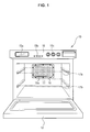
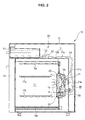
- FIGS. 1 and 2 show, a heating apparatus for cooking in accordance with a first embodiment of the present invention.
- the heating apparatus for cooking includes a main body 10 having a cooking chamber 11 installed therein, and a door 12 vertically rotatably installed (i.e. rotatably installed about a horizontal axis) on the front surface of the main body 10 for closing the opened front surface of the cooking chamber 11.
- the heating apparatus for cooking also includes a hot air chamber 18 installed at the rear portion of the inside of the cooking chamber 11, a heater 20 installed in the hot air chamber 18, a blowing device 21 for circulating air in the cooking chamber 11 to the hot air chamber 18, a steam-generating device 30 installed in the hot air chamber 18 for supplying steam to the cooking chamber 11, and a water supply device 50 installed at the upper portion of the cooking chamber 11 for supplying water to the steam-generating device 30.
- the main body 10 includes an outer case 13 which may be made of plate iron, and an inner case 14 installed in the outer case 13 such that the outer surface of the inner case 14 is separated from the inner surface of the outer case 13 for forming the cooking chamber 11.
- the inner case 14 has a first case 14a forming the inner surface of the inner case 14 and a second case 14b forming the outer surface of the inner case 14, which are separated from each other. A space is formed between the first case 14a and the second case 14b, thereby thermally insulating the cooking chamber 11 from the outside.
- an operating unit 15 including a display 15a for displaying the operational state of the heating apparatus for cooking, various operating buttons 15b, and manipulation switches 15c is installed at the upper part of the door 12 on the front surface of the main body 10.
- Shelves 17a and 17b for placing foods thereon are respectively installed at upper and lower portions of the inside of the cooking chamber 11.
- An upper heater 16a and a lower heater 16b for heating the foods placed on the shelves 17a and 17b are respectively installed at the upper and lower portions of the inside of the cooking chamber 11.
- the upper heater 16a is installed at the upper portion of the inside of the cooking chamber 11
- the lower heater 16b is installed on the outer lower surface of the cooking chamber 11. That is, the lower heater 16b contacts the outer surface of the bottom of the first case 14a.
- the above structure protects the lower heater 16b from foreign substances falling from the foods placed in the cooking chamber 11, and transmits heat of the lower heater 16b to the inside of the cooking chamber 11 through the bottom of the first case 14a.
- the hot air chamber 18 installed at the rear portion of the inside of the cooking chamber 11 is formed by a depression 14c in the rear surface of the first case 14a of a designated depth.
- the hot air chamber 18 of this embodiment of the present invention is formed at the rear portion of the inside of the cooking chamber 11, the hot air chamber 18 may be formed at both side surfaces of the cooking chamber 11.
- the blowing device 21, for circulating air to the hot air chamber 18, includes a centrifugal air blast fan 21a installed in the hot air chamber 18, and a driving motor 21 b installed at the outer surface of the rear portion of the hot air chamber 18 for driving the air blast fan 21 a.
- the heater 20 is installed adjacent to the outer periphery of the air blast fan 21a in the hot air chamber 18.
- the air blast fan 21a is operated when the heater 20 is operated, the air in the cooking chamber 11 is drawn in to the air blast fan 21a, and is exhausted to the outside of the air blast fan 21 a in the radial direction of the air blast fan 21 a. Then, the exhausted air is heated by the heater 20, and is supplied to the inside of the cooking chamber 11.
- the above circulation of the hot air improves cooking of the foods placed in the cooking chamber 11.
- the steam-generating device in the hot air chamber 18 includes a hermetic heating tank 31 containing a designated quantity of water, a steam-generating heater 32 for heating the water contained in the heating tank 31, and a water level sensor 33 for sensing the level of the water contained in the heating tank 31.
- the heating tank 31 includes a heating container 31 a having a rectangular hexahedral structure provided with an open upper surface, and a cover member 31 b for closing the opened upper surface of the heating container 31 a.
- the cover member 31 b is provided with steam exhaust holes 34a and 34b respectively formed at both sides thereof.
- the cover member 31 b is fixed to the inner rear surface of the hot air chamber 18 through fixing members 36 installed at upper portions of the rear surfaces of both sides thereof, and the heating container 31 a is detachably attached to the lower portion of the cover member 31 b. For this reason, a plurality of fixing bolts 37 which extendupward are fixed to the inside of the heating container 31a.
- fixing nuts 38 are respectively coupled with the corresponding upper ends of the fixing bolts 37, thereby fixing the fixing bolts 37.
- a packing member 39 for maintaining an airtight state is interposed between the upper end of the heating container 31 a and the cover member 31 b.
- Both ends of the steam-generating heater 32 are fixed to the cover member 31 b such that the main portion of the steam-generating heater 32 can be submerged in water in the heating container 31a, and an end of the water level sensor 33 is fixed to the cover member 31b such that the main portion of the water level sensor 33 can be submerged in the water in the heating container 31a.
- a water supply hole 40 for supplying water to the heating container 31 a therethrough is formed through the cover member 31 b, and a water supply pipe 55 of the water supply device 50, which will be described later, is connected to the water supply hole 40.
- Exhaust guide pipes 35a and 35b having a designated length for guiding exhaust steam are respectively connected to steam exhaust holes 34a and 34b formed at both sides of the cover member 31 b.
- the steam-generating device 30 generates steam by heating water supplied to the heating tank 31 a using the steam-generating heater 32, and supplies the steam to the cooking chamber 11 through the exhaust guide pipes 35a and 35b. Since the steam-generating device 30 is installed in the hot air chamber 18 at the rear of the cooking chamber 11, it is possible to prevent the steam-generating device 30 from being contaminated by remnants or oil falling from the foods.
- the heating container 31a is separated from the cover member 31 b simply by loosening the fixing nuts 38 installed at the upper portion of the cover member 31 b, and then the inside of the heating container 31 a and the outer surface of the steam-generating heater 32 can be conveniently cleaned.
- the above steam-generating device 30 heats the outer surface of the heating tank 31 using the heater 20 in the hot air chamber 18, thereby increasing efficiency in generating the steam, and uniformly supplies the steam exhausted through the exhaust guide pipes 35a and 35b to the cooking chamber 11 using the air circulating into the hot air chamber 18, thereby improving cooking.
- the water supply device 50 placed in the upper portion of the cooking chamber 11 includes a water tank 51 which may be of a drawer-type installed above the cooking chamber 11 so that the water tank 51 can be drawn forward, a water supply pump 52 for supplying water from the water tank 51 to the steam-generating device 30, and a plurality of water supply pipes 53, 54 and 55 for connecting the water tank 51 and the water supply tank 52 and connecting the water supply tank 52 and the heating tank 31.
- the water supply pipe 53 interposed between the water tank 51 and the water supply pump 52 has a length sufficient to allow the water tank 51 to be drawn forward.
- a user can draw the water tank 51 forward from the front surface of the main body 10 and fill the water tank 51 with water, and the water contained in the water tank 51 can be supplied to the heating tank 31 by the operation of the water supply pump 52.
- the operation of the water supply pump 52 is controlled by the water level sensor 33 installed in the heating tank 31 of the steam-generating device 30 for adjusting the level of the water in the heating tank 31.
- the upper and lower heaters 16a and 16b placed at the upper and lower portions of the cooking chamber 11 and the heater 20 placed in the hot air chamber 18 are operated and the air blast fan 21a in the hot air chamber 18 is operated.
- the foods placed in the cooking chamber 11 are heated by heat generated from the upper and lower heaters 16a and 16b and hot air circulated through the hot air chamber 18 by the operation of the air blast fan 21a.
- the user When a user wants to cook foods in the cooking chamber 11 using steam supplied to the cooking chamber 11, the user first fills the water tank 51 installed above the cooking chamber 11 with water and then operates the steam-generating device 30. Then, water is supplied from the water tank 51 to the heating tank 31 in the hot air chamber 18 by the operation of the water supply pump 52.
- a controller (not shown) controls the operation of the water supply pump 52 based on the sensing operation of the water level sensor 33 installed in the heating tank 31, thereby achieving the above-described water supply.
- the controller supplies power to the steam-generating heater 32 so that the water in the heating tank 31 is heated by the steam-generating heater 32 and is changed to steam.
- the steam is supplied to the cooking chamber 11 through the exhaust guide pipes 35a and 35b.
- the steam exhausted through the exhaust guide pipes 35a and 35b is uniformly supplied to the inside of the cooking chamber 11 by the air circulating into the hot air chamber 18, thereby preventing the foods from being dried and improving cooking.
- water in the heating tank 31 of the steam-generating device 30 of the present embodiment is heated by the heater 20 in the hot air chamber 18 as well as the steam-generating heater 32. Accordingly, since the water in the heating tank 31 is rapidly heated and efficiency in generating steam is improved, the steam-generating device 30 employs the steam-generating heater 32 having a low capacity yet can still generate a sufficient quantity of steam.
- the user When a user wants to clean the inside of the heating tank 31 and the steam-generating heater 32, the user first separates the hot air chamber cover 19 from the rear portion of the cooking chamber 11 and then separates the fixing nuts 38 from the upper surface of the heating tank 31. Thereby, the heating container 31a of the heating tank 31 is easily separated from the cover member 31 b, thus allowing the user to easily clean the inside of the heating tank 31. Further, the separation of the heating container 31a from the cover member 31 b exposes the steam-generating heater 32 fixed to the cover member 31b to the outside, thus allowing the user to easily remove foreign substances from the surface of the steam-generating heater 32.
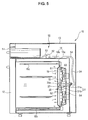
- FIG. 5 illustrates a heating apparatus for cooking in accordance with a second embodiment of the present invention.
- the heating apparatus for cooking of the second embodiment includes first and second heaters 61 and 62 respectively installed at upper and lower portions of the hot air chamber 18, and first and second air blast fans 63 and 64 respectively installed at the upper and lower portions of the hot air chamber 18.
- the steam-generating device 30, which is also employed by the heating apparatus of the first embodiment, is interposed between the first heater 61 and the second heater 62.
- This configuration of the heating apparatus of the second embodiment causes the heating tank 31 of the steam-generating device 30 to be heated by the first and second heaters 61 and 62 as well as the steam-generating heater 32, thereby having improved steam-generating effects compared to the heating apparatus of the first embodiment.
- the heating apparatus for cooking of the second embodiment which includes the small-sized heating tank 31 and steam-generating heater 32, generates a sufficient quantity of steam.
- Other parts of the heating apparatus for cooking of the second embodiment are substantially the same as those of the heating apparatus for cooking of the first embodiment, and detailed descriptions thereof is thus omitted.
- the above-described embodiments of the present invention provide a heating apparatus for cooking having a steam-generating device, which is installed in a hot air chamber in the rear of a cooking chamber, so as to prevent the steam-generating device from being contaminated by debris or oil falling from foods placed in the cooking chamber, thereby operating hygienically.
- a heating tank installed in the hot air chamber of the heating apparatus for cooking of the present invention is easily disassembled, the heating tank and the steam-generating heater are easily cleaned.
- the steam-generating devices of the heating apparatus for cooking of the above-described embodiments of the present invention are installed in the hot air chamber, water contained in the heating tanks is heated by heater(s) in the hot air improved. Accordingly, the heating apparatuses for cooking employ the steam-generating heater having a low capacity, and are still able to generate sufficient steam.
- the steam which is exhausted through exhaust guide pipes of the steam-generating device, is uniformly supplied to the cooking chamber by air circulated into the hot air chamber, giving heating apparatuses for cooking of the above-described embodiments of the present invention improved cooking effects.
Landscapes
- Engineering & Computer Science (AREA)
- Chemical & Material Sciences (AREA)
- Combustion & Propulsion (AREA)
- Mechanical Engineering (AREA)
- General Engineering & Computer Science (AREA)
- Food Science & Technology (AREA)
- Electric Ovens (AREA)
Abstract
A heating apparatus for cooking having a steam-generating device (30), which is easily cleaned and hygienically used and has improved steam-generating effects. The heating apparatus includes a main body (10) having a cooking chamber (11); a hot air chamber (18) formed in at least one of either side and or rear surfaces of the cooking chamber (11) to facilitate supply of hot air to the cooking chamber (11); and a steam-generating device (30) installed in the hot air chamber (18) operable to supplying steam to the cooking chamber (11).
Description
- The present invention relates to heating apparatus for cooking.
- Generally, heating apparatuses for cooking include an electronic oven range, an electric oven range, and a gas oven range, for example. The electronic oven range, e.g., a microwave oven, supplies high-frequency waves generated from a magnetron to the inside of a cooking chamber, thereby cooking foods placed in the cooking chamber using heat generated from the foods themselves. The electric oven range or the gas oven range transmits heat, generated from the operation of an electric heater or the combustion of a gas, to the inside of a cooking chamber, thereby cooking foods in the cooking chamber. Since moisture of the foods is evaporated during cooking, the above heating apparatuses for cooking are disadvantageous in that the foods are easily dried. To address this disadvantage, a steam-generating device for preventing foods from being dried and improving cooking effects can be installed in the heating apparatuses for cooking.
- EP Patent No. 0277337 discloses a heating apparatus for cooking comprising a steam-generating device having a container shape installed on the bottom of a cooking chamber, and a water tank of a drawer-type installed above the cooking chamber for supplying water to the steam-generating device.
- Japanese Laid-open Patent No. 2004-20005 discloses a heating apparatus using high-frequency waves comprising an evaporation tray installed on the bottom of a cooking chamber, a heater for heating water in the evaporation tray, and a water tank installed at a side of the cooking chamber for supplying water to the evaporation tray.
- The above heating apparatuses supply water from the water tank to the steam-generating device or the evaporation tray, and heat the water supplied to the steam-generating device or the evaporation tray, using the heater to generate steam. Steam is then supplied to the cooking chamber.
- Since the steam-generating devices of the above heating apparatuses for cooking are installed below the cooking chambers, debris or oil falling from foods placed in the cooking chambers can be introduced into the steam-generating devices, thereby contaminating water in the steam-generating devices and causing hygiene problems. Further, it is difficult to separate this type of steam-generating device, from the main body of a heating apparatus for repair.
- It is an aim of preferred embodiments of the present invention to address a disadvantage of the prior art, whether identified herein, or otherwise.
- According to a first aspect of the present invention, there is provided heating apparatus for cooking including: a main body having a cooking chamber; a hot air chamber to facilitate supply of hot air to the cooking chamber; and a steam-generating device in the hot air chamber operable to supply steam to the cooking chamber.
- The hot air chamber may include a heater and a fan, and the steam-generating device may be heated indirectly by the heater and hot air in the hot air chamber. Since the steam-generating device of the heating apparatus for cooking is not thermally isolated from other heat sources efficiency in generating steam is increased.
- The heating apparatus may also include a water supply device operable to supply water to the steam-generating device.
- The water supply device may include a water tank above the cooking chamber; a water supply pump operable to supply water from the water tank to the steam-generating device; a plurality of water supply pipes connecting the water tank and the water supply pump, and connecting the water supply pump to the steam-generating device.
- The steam-generating device may include a water supply pipe arranged to receive water from the water supply device; a heating tank for containing water; a steam-generating heater operable to heat water contained in the heating tank; and exhaust pipes arranged to exhaust generated steam to the cooking chamber. By providing a steam-generating device which is heated by its peripheral heat as well as its heater, steam-generating effects are increased.
- The hot air chamber may include a first heater and a second heater, which are separated from each other, and the steam-generating device may be interposed between the first heater and the second heater.
- The hot air chamber may further include a first fan operable to blow air heated by the first heater and a second fan operable to blow air heated by the second heater.
- The heating apparatus may also include a hot air chamber cover, provided with a plurality of air vents formed therethrough, detachably attached to the inside of the cooking chamber such that the hot air chamber cover covers a surface of the hot air chamber, preferably a front surface.
- The hot air chamber may be located in at least one of a rear surface and or side surfaces of the cooking chamber.
- According to second aspect of the present invention, there is provided a heating apparatus for cooking including: a main body having a cooking chamber; a hot air chamber formed in at least one of side and rear surfaces of the cooking chamber to facilitate supply of hot air to the cooking chamber; and a steam-generating device detachably installed in the hot air chamber operable to supply steam to the cooking chamber.
- The steam-generating device may include a heating tank having a heating container having an opened upper end surface, and a cover member closing the opened upper end surface of the heating container, and the cover member of the heating tank may be fixed to the inside of the hot air chamber, and the heating container of the heating tank may be detachably attached to the cover member. Thus, the steam-generating device is easily and hygienically cleanable.
- The cover member may be provided with a steam-generating heater operable to heat water contained in the heating tank, a water supply pipe arranged to supply water to the inside of the heating tank, and exhaust guide pipes arranged to guide exhaust of steam.
- A packing member may be placed at an interface between the heating container and the cover member.
- A water level sensor operable to sense a level of the water contained in the heating container may be installed in the cover member.
- According to a third aspect of the present invention, there is provided a steam supply device for a heating apparatus having a cooking chamber and a hot air chamber to facilitate supply of hot air to the cooking chamber, including: water tank installed above the cooking chamber; a heating tank in the hot air chamber; a water supply pump operable to supply water in the water tank to the heating tank; and a steam-generating heater in the heating tank operable to convert water contained in the heating tank into steam.
- According to the present invention there is provided an apparatus and method as set forth in the appended claims. Preferred features of the invention will be apparent from the dependent claims, and the description which follows.
- For a better understanding of the invention, and to show how embodiments of the same may be carried into effect, reference will now be made, by way of example, to the accompanying diagrammatic drawings in which:
- FIG. 1 is a perspective view of a heating apparatus for cooking in accordance with a first embodiment of the present invention;
- FIG. 2 is a longitudinal-sectional view of the heating apparatus for cooking of FIG 1;
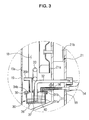
- FIG. 3 is an enlarged view of portion III of FIG. 2;
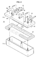
- FIG. 4 is an exploded perspective view of a steam-generating device of the heating apparatus for cooking of FIG 1; and
- FIG. 5 is a longitudinal-sectional view of a heating apparatus for cooking in accordance with a second embodiment of the present invention.
- FIGS. 1 and 2 show, a heating apparatus for cooking in accordance with a first embodiment of the present invention. The heating apparatus for cooking includes a
main body 10 having acooking chamber 11 installed therein, and adoor 12 vertically rotatably installed (i.e. rotatably installed about a horizontal axis) on the front surface of themain body 10 for closing the opened front surface of thecooking chamber 11. The heating apparatus for cooking also includes ahot air chamber 18 installed at the rear portion of the inside of thecooking chamber 11, aheater 20 installed in thehot air chamber 18, a blowingdevice 21 for circulating air in thecooking chamber 11 to thehot air chamber 18, a steam-generatingdevice 30 installed in thehot air chamber 18 for supplying steam to thecooking chamber 11, and awater supply device 50 installed at the upper portion of thecooking chamber 11 for supplying water to the steam-generating device 30. - The
main body 10 includes anouter case 13 which may be made of plate iron, and aninner case 14 installed in theouter case 13 such that the outer surface of theinner case 14 is separated from the inner surface of theouter case 13 for forming thecooking chamber 11. Theinner case 14 has afirst case 14a forming the inner surface of theinner case 14 and asecond case 14b forming the outer surface of theinner case 14, which are separated from each other. A space is formed between thefirst case 14a and thesecond case 14b, thereby thermally insulating thecooking chamber 11 from the outside. As shown in FIG. 1, anoperating unit 15 including adisplay 15a for displaying the operational state of the heating apparatus for cooking,various operating buttons 15b, andmanipulation switches 15c is installed at the upper part of thedoor 12 on the front surface of themain body 10. - Shelves 17a and 17b for placing foods thereon are respectively installed at upper and lower portions of the inside of the
cooking chamber 11. Anupper heater 16a and alower heater 16b for heating the foods placed on theshelves cooking chamber 11. Here, theupper heater 16a is installed at the upper portion of the inside of thecooking chamber 11, and thelower heater 16b is installed on the outer lower surface of thecooking chamber 11. That is, thelower heater 16b contacts the outer surface of the bottom of thefirst case 14a. The above structure protects thelower heater 16b from foreign substances falling from the foods placed in thecooking chamber 11, and transmits heat of thelower heater 16b to the inside of thecooking chamber 11 through the bottom of thefirst case 14a. - As shown in FIG. 2, the
hot air chamber 18 installed at the rear portion of the inside of thecooking chamber 11 is formed by adepression 14c in the rear surface of thefirst case 14a of a designated depth. A hotair chamber cover 19, provided with a plurality ofair vents 19a (in FIG. 1) formed therethrough, is detachably installed on the rear surface of the inside of thecooking chamber 11 such that the hotair chamber cover 19 covers the front surface of thehot air chamber 18. Although thehot air chamber 18 of this embodiment of the present invention is formed at the rear portion of the inside of thecooking chamber 11, thehot air chamber 18 may be formed at both side surfaces of thecooking chamber 11. - The blowing
device 21, for circulating air to thehot air chamber 18, includes a centrifugalair blast fan 21a installed in thehot air chamber 18, and a drivingmotor 21 b installed at the outer surface of the rear portion of thehot air chamber 18 for driving theair blast fan 21 a. Theheater 20 is installed adjacent to the outer periphery of theair blast fan 21a in thehot air chamber 18. When theair blast fan 21a is operated when theheater 20 is operated, the air in thecooking chamber 11 is drawn in to theair blast fan 21a, and is exhausted to the outside of theair blast fan 21 a in the radial direction of theair blast fan 21 a. Then, the exhausted air is heated by theheater 20, and is supplied to the inside of thecooking chamber 11. The above circulation of the hot air improves cooking of the foods placed in thecooking chamber 11. - As shown in FIGS. 3 and 4, the steam-generating device in the
hot air chamber 18 includes ahermetic heating tank 31 containing a designated quantity of water, a steam-generatingheater 32 for heating the water contained in theheating tank 31, and awater level sensor 33 for sensing the level of the water contained in theheating tank 31. - The
heating tank 31 includes aheating container 31 a having a rectangular hexahedral structure provided with an open upper surface, and acover member 31 b for closing the opened upper surface of theheating container 31 a. Thecover member 31 b is provided withsteam exhaust holes cover member 31 b is fixed to the inner rear surface of thehot air chamber 18 throughfixing members 36 installed at upper portions of the rear surfaces of both sides thereof, and theheating container 31 a is detachably attached to the lower portion of thecover member 31 b. For this reason, a plurality offixing bolts 37 which extendupward are fixed to the inside of theheating container 31a. After upper ends of thefixing bolts 37 pass through thecover member 31 b,fixing nuts 38 are respectively coupled with the corresponding upper ends of thefixing bolts 37, thereby fixing thefixing bolts 37. A packingmember 39 for maintaining an airtight state is interposed between the upper end of theheating container 31 a and thecover member 31 b. - Both ends of the steam-generating
heater 32 are fixed to thecover member 31 b such that the main portion of the steam-generatingheater 32 can be submerged in water in theheating container 31a, and an end of thewater level sensor 33 is fixed to thecover member 31b such that the main portion of thewater level sensor 33 can be submerged in the water in theheating container 31a. Awater supply hole 40 for supplying water to theheating container 31 a therethrough is formed through thecover member 31 b, and awater supply pipe 55 of thewater supply device 50, which will be described later, is connected to thewater supply hole 40.Exhaust guide pipes exhaust holes cover member 31 b. - The steam-generating
device 30 generates steam by heating water supplied to theheating tank 31 a using the steam-generatingheater 32, and supplies the steam to thecooking chamber 11 through theexhaust guide pipes device 30 is installed in thehot air chamber 18 at the rear of thecooking chamber 11, it is possible to prevent the steam-generatingdevice 30 from being contaminated by remnants or oil falling from the foods. When a user wants to clean the steam-generatingdevice 30, theheating container 31a is separated from thecover member 31 b simply by loosening the fixingnuts 38 installed at the upper portion of thecover member 31 b, and then the inside of theheating container 31 a and the outer surface of the steam-generatingheater 32 can be conveniently cleaned. - The above steam-generating
device 30 heats the outer surface of theheating tank 31 using theheater 20 in thehot air chamber 18, thereby increasing efficiency in generating the steam, and uniformly supplies the steam exhausted through theexhaust guide pipes cooking chamber 11 using the air circulating into thehot air chamber 18, thereby improving cooking. - As shown in FIGS. 1 and 2, the
water supply device 50 placed in the upper portion of thecooking chamber 11 includes awater tank 51 which may be of a drawer-type installed above thecooking chamber 11 so that thewater tank 51 can be drawn forward, awater supply pump 52 for supplying water from thewater tank 51 to the steam-generatingdevice 30, and a plurality ofwater supply pipes water tank 51 and thewater supply tank 52 and connecting thewater supply tank 52 and theheating tank 31. Here, thewater supply pipe 53 interposed between thewater tank 51 and thewater supply pump 52 has a length sufficient to allow thewater tank 51 to be drawn forward. - In the above configuration of the
water supply device 50, a user can draw thewater tank 51 forward from the front surface of themain body 10 and fill thewater tank 51 with water, and the water contained in thewater tank 51 can be supplied to theheating tank 31 by the operation of thewater supply pump 52. Here, the operation of thewater supply pump 52 is controlled by thewater level sensor 33 installed in theheating tank 31 of the steam-generatingdevice 30 for adjusting the level of the water in theheating tank 31. - Hereinafter, the overall operation of the heating apparatus for cooking and the cleaning method of the steam-generating device of the heating apparatus for cooking will be described in detail.
- When foods are placed on either of the
shelves cooking chamber 11 and the heating apparatus for cooking is operated, the upper andlower heaters cooking chamber 11 and theheater 20 placed in thehot air chamber 18 are operated and theair blast fan 21a in thehot air chamber 18 is operated. The foods placed in thecooking chamber 11 are heated by heat generated from the upper andlower heaters hot air chamber 18 by the operation of theair blast fan 21a. - When a user wants to cook foods in the
cooking chamber 11 using steam supplied to thecooking chamber 11, the user first fills thewater tank 51 installed above thecooking chamber 11 with water and then operates the steam-generatingdevice 30. Then, water is supplied from thewater tank 51 to theheating tank 31 in thehot air chamber 18 by the operation of thewater supply pump 52. Here, a controller (not shown) controls the operation of thewater supply pump 52 based on the sensing operation of thewater level sensor 33 installed in theheating tank 31, thereby achieving the above-described water supply. When the level of the water in theheating tank 31 reaches a proper level, the controller supplies power to the steam-generatingheater 32 so that the water in theheating tank 31 is heated by the steam-generatingheater 32 and is changed to steam. The steam is supplied to thecooking chamber 11 through theexhaust guide pipes exhaust guide pipes cooking chamber 11 by the air circulating into thehot air chamber 18, thereby preventing the foods from being dried and improving cooking. - Here, water in the
heating tank 31 of the steam-generatingdevice 30 of the present embodiment is heated by theheater 20 in thehot air chamber 18 as well as the steam-generatingheater 32. Accordingly, since the water in theheating tank 31 is rapidly heated and efficiency in generating steam is improved, the steam-generatingdevice 30 employs the steam-generatingheater 32 having a low capacity yet can still generate a sufficient quantity of steam. The steam-generatingdevice 30, which employs the steam-generatingheater 32 having a low capacity, has low production costs. - When a user wants to clean the inside of the
heating tank 31 and the steam-generatingheater 32, the user first separates the hot air chamber cover 19 from the rear portion of thecooking chamber 11 and then separates the fixingnuts 38 from the upper surface of theheating tank 31. Thereby, theheating container 31a of theheating tank 31 is easily separated from thecover member 31 b, thus allowing the user to easily clean the inside of theheating tank 31. Further, the separation of theheating container 31a from thecover member 31 b exposes the steam-generatingheater 32 fixed to thecover member 31b to the outside, thus allowing the user to easily remove foreign substances from the surface of the steam-generatingheater 32. - FIG. 5 illustrates a heating apparatus for cooking in accordance with a second embodiment of the present invention. The heating apparatus for cooking of the second embodiment includes first and
second heaters hot air chamber 18, and first and secondair blast fans hot air chamber 18. The steam-generatingdevice 30, which is also employed by the heating apparatus of the first embodiment, is interposed between thefirst heater 61 and thesecond heater 62. This configuration of the heating apparatus of the second embodiment causes theheating tank 31 of the steam-generatingdevice 30 to be heated by the first andsecond heaters heater 32, thereby having improved steam-generating effects compared to the heating apparatus of the first embodiment. The heating apparatus for cooking of the second embodiment, which includes the small-sized heating tank 31 and steam-generatingheater 32, generates a sufficient quantity of steam. Other parts of the heating apparatus for cooking of the second embodiment are substantially the same as those of the heating apparatus for cooking of the first embodiment, and detailed descriptions thereof is thus omitted. - The above-described embodiments of the present invention provide a heating apparatus for cooking having a steam-generating device, which is installed in a hot air chamber in the rear of a cooking chamber, so as to prevent the steam-generating device from being contaminated by debris or oil falling from foods placed in the cooking chamber, thereby operating hygienically.
- Since a heating tank installed in the hot air chamber of the heating apparatus for cooking of the present invention is easily disassembled, the heating tank and the steam-generating heater are easily cleaned.
- Since the steam-generating devices of the heating apparatus for cooking of the above-described embodiments of the present invention are installed in the hot air chamber, water contained in the heating tanks is heated by heater(s) in the hot air improved. Accordingly, the heating apparatuses for cooking employ the steam-generating heater having a low capacity, and are still able to generate sufficient steam.
- The steam, which is exhausted through exhaust guide pipes of the steam-generating device, is uniformly supplied to the cooking chamber by air circulated into the hot air chamber, giving heating apparatuses for cooking of the above-described embodiments of the present invention improved cooking effects.
- Although embodiments of the present invention have been shown and described, it would be appreciated by those skilled in the art that changes may be made in these embodiments without departing from the principles of the invention, the scope of which is defined in the claims.
- Attention is directed to all papers and documents which are filed concurrently with or previous to this specification in connection with this application and which are open to public inspection with this specification, and the contents of all such papers and documents are incorporated herein by reference.
- All of the features disclosed in this specification (including any accompanying claims, abstract and drawings), and/or all of the steps of any method or process so disclosed, may be combined in any combination, except combinations where at least some of such features and/or steps are mutually exclusive.
- Each feature disclosed in this specification (including any accompanying claims, abstract and drawings) may be replaced by alternative features serving the same, equivalent or similar purpose, unless expressly stated otherwise. Thus, unless expressly stated otherwise, each feature disclosed is one example only of a generic series of equivalent or similar features.
- The invention is not restricted to the details of the foregoing embodiment(s). The invention extends to any novel one, or any novel combination, of the features disclosed in this specification (including any accompanying claims, abstract and drawings), or to any novel one, or any novel combination, of the steps of any method or process so disclosed.
Claims (23)
- A heating apparatus for cooking comprising:a main body (10) having a cooking chamber (11);a hot air chamber (18) to facilitate supply of hot air to the cooking chamber (11); anda steam-generating device (30) in the hot air chamber (18), operable to supply steam to the cooking chamber (11).
- The heating apparatus according to claim 1, wherein the hot air chamber (18) includes a heater (20) and a fan (21), and
wherein the steam-generating device is heated indirectly by the heater (20) and hot air in the hot air chamber. - The heating apparatus according to claim 1 or 2, further comprising a water supply (50), operable to device supply water to the steam-generating device (30).
- The heating apparatus according to claim 3, wherein the water supply device (50) includes:a water tank (51) above the cooking chamber (11);a water supply pump (52), operable to supply water from the water tank (51) to the steam-generating device (30); anda plurality of water supply pipes (53, 54), connecting the water tank (51) to the water supply pump (52), and connecting the water supply pump (52) to the steam-generating device (30).
- The heating apparatus according to claim 3 or 4, wherein the steam-generating device (30) includes:a water supply pipe, arranged to receive water from the water supply device (50);a heating tank (31) for containing water;a steam-generating heater (32), operable to heat the water contained in the heating tank (21); andexhaust pipes (35) arranged to exhaust generated steam to the cooking chamber (11).
- The heating apparatus according to any preceding claim, wherein the hot air chamber (18) includes a first heater (61) and a second heater (62) separated from the first heater (61), and the steam-generating device (30) is between the first heater (61) and the second heater (62).
- The heating apparatus according to claim 6, wherein the hot air chamber 18) includes a first fan (63) operable to blow air heated by the first heater (61) and a second fan (64) operable to blow air heated by the second heater (62).
- The heating apparatus according any preceding to claim, further comprising a hot air chamber cover (19) having a plurality of air vents (19a) formed therethrough and detachably attached to the inside of the cooking chamber (11) such that the hot air chamber cover (19) covers a surface of the hot air chamber (18).
- The heating apparatus of any preceding claim, wherein the hot air chamber (18) is located in at least one of a rear surface and/or side surfaces of the cooking chamber (11).
- A heating apparatus for cooking comprising:a main body (10) having a cooking chamber (11);a hot air chamber (18) formed in at least one of rear and side surfaces of the cooking chamber (11) to facilitate supply of hot air to the cooking chamber(11); anda steam-generating device (30) detachably installed in the hot air chamber (18) operable to supply steam to the cooking chamber (11).
- The heating apparatus according to claim 10, wherein the steam-generating device (30) includes a heating tank (31) having a heating container (31 a) having an open upper end surface, and a cover member (31 b) closing the open upper end surface, and
wherein the cover member (31b) of the heating tank (31) is fixed to an inside of the hot air chamber (18), and the heating container (31 a) of the heating tank (31) is detachably attached to the cover member (31b). - The heating apparatus according to claim 11, wherein the cover member (31 b) has a steam-generating heater (32) operable to heat water contained in the heating tank (31), a water supply pipe (55) arranged to supply water to the inside of the heating tank (31), and exhaust pipes (34) arranged to exhaust generated steam.
- The heating apparatus according to claim 11 or 12, wherein a packing member (39) is placed at an interface between the heating container (31 a) and the cover member (31 b).
- The heating apparatus according to claim 11, 12 or 13, wherein a water level sensor (33) operable to sense a level of the water contained in the heating container (31) is installed in the cover member (31 b).
- The heating apparatus according to any one of claims 10-14, further comprising a hot air chamber (19) cover having a plurality of air vents (19a) formed therethrough and detachably attached to the inside of the cooking chamber such that the hot air chamber cover (19) covers the front surface of the hot air chamber (11).
- The heating apparatus according to claim 12 or of any one of claims 13-15 as dependent on claim 12, wherein ends of the steam-generating heater (32) are fixed to the cover member (31 b) such that a portion of the steam-generating heater (32) can in use be covered by water contained in the heating container (31 a).
- The heating apparatus according to claim 12 or of any one of claims 13-16 as dependent on claim 12, wherein the exhaust pipes (34) are positioned so as to uniformly supply exhausted steam to the cooking chamber (11) using air circulating in the hot air chamber (18).
- The heating apparatus according to claim 9, further comprising:a water supply device (50) including a water tank (51) and a water supply pump (52) operable to supply water from the water tank (51) to the steam-generating device (30).
- The heating apparatus according to claim 18, wherein the water tank is of a drawer-type and is drawable forward.
- The heating apparatus according to claim 19, wherein a water supply pipe (53) connects the water tank (51) and the water supply pump (52), the water supply pipe (53) being of sufficient length allow the water tank (51) to be drawn forward.
- The heating apparatus according to claim 19, wherein the water tank (51) is fillable when drawn forward.
- The heating apparatus according to claim 18, 19, 20 or 21 wherein the water tank (51) is disposed above the cooking chamber (11).
- The heating apparatus according to any one of claims 18-22, wherein operation of the water supply pump (52) is controlled according to a sensed water level sensed by a water level sensor (33) in the heating tank (31).
Applications Claiming Priority (1)
| Application Number | Priority Date | Filing Date | Title |
|---|---|---|---|
| KR1020040055530A KR20060006472A (en) | 2004-07-16 | 2004-07-16 | Heating cooker |
Publications (1)
| Publication Number | Publication Date |
|---|---|
| EP1617148A1 true EP1617148A1 (en) | 2006-01-18 |
Family
ID=35063337
Family Applications (1)
| Application Number | Title | Priority Date | Filing Date |
|---|---|---|---|
| EP05253047A Withdrawn EP1617148A1 (en) | 2004-07-16 | 2005-05-18 | Heating apparatus for cooking |
Country Status (3)
| Country | Link |
|---|---|
| US (1) | US7323662B2 (en) |
| EP (1) | EP1617148A1 (en) |
| KR (1) | KR20060006472A (en) |
Cited By (18)
| Publication number | Priority date | Publication date | Assignee | Title |
|---|---|---|---|---|
| EP1898156A1 (en) * | 2006-09-06 | 2008-03-12 | Ching-Hsiang Wang | Steam oven |
| EP1942320A2 (en) * | 2007-01-08 | 2008-07-09 | Samsung Electronics Co., Ltd. | Water level sensor, steam generator having the same, heating cooker having the steam generator and control method thereof |
| WO2009038995A1 (en) * | 2007-09-19 | 2009-03-26 | Premark Feg L.L.C. | Steam cooking apparatus with steam flushing system |
| FR2934360A1 (en) * | 2008-07-22 | 2010-01-29 | Csi | Universal oven for cooking e.g. meat, has suction pump sucking water from removable water reservoir that is placed external to vapor generator and is filled with water at any time, without interruption of cooking chamber |
| WO2010083387A3 (en) * | 2009-01-16 | 2011-11-24 | Mag Aerospace Industries, Inc. | Oven steam generator system and method for generating steam |
| WO2016016860A1 (en) * | 2014-07-31 | 2016-02-04 | I.R.C.A. S.P.A. Industria Resistenze Corazzate E Affini | Domestic oven |
| WO2016030265A1 (en) * | 2014-08-27 | 2016-03-03 | BSH Hausgeräte GmbH | Domestic cooking appliance comprising a steam inlet |
| EP3207801A1 (en) | 2016-02-17 | 2017-08-23 | Sebp Pavailler | Steam-generating device and oven comprising such a device; method of steam generation and cooking method using such a method. |
| EP3372900A1 (en) * | 2017-03-07 | 2018-09-12 | Whirlpool Corporation | Oven with forced convection steam assembly |
| EP3550210A1 (en) * | 2018-04-04 | 2019-10-09 | LG Electronics Inc. | Cooking applicance |
| US10619862B2 (en) | 2018-06-28 | 2020-04-14 | Whirlpool Corporation | Frontal cooling towers for a ventilation system of a cooking appliance |
| US10627116B2 (en) | 2018-06-26 | 2020-04-21 | Whirlpool Corporation | Ventilation system for cooking appliance |
| US10660162B2 (en) | 2017-03-16 | 2020-05-19 | Whirlpool Corporation | Power delivery system for an induction cooktop with multi-output inverters |
| EP3722679A1 (en) * | 2019-04-10 | 2020-10-14 | Bonferraro S.p.A. | Professional cooking oven with steam generator |
| US10837651B2 (en) | 2015-09-24 | 2020-11-17 | Whirlpool Corporation | Oven cavity connector for operating power accessory trays for cooking appliance |
| WO2021246975A1 (en) * | 2020-06-02 | 2021-12-09 | Femas Metal San. Ve Tic. A.S. | Oven with steam assembly |
| US11825976B2 (en) * | 2019-05-10 | 2023-11-28 | Electrolux Home Products, Inc. | Reservoir for steam cooking |
| EP4532986A4 (en) * | 2022-06-03 | 2026-03-04 | Femas Metal San Ve Tic A S | STEAM OVEN WITH WATER TANK |
Families Citing this family (29)
| Publication number | Priority date | Publication date | Assignee | Title |
|---|---|---|---|---|
| KR101041079B1 (en) * | 2006-09-28 | 2011-06-13 | 삼성전자주식회사 | Leveling unit, steam generator with same, and heating cooker with steam generator |
| KR100889132B1 (en) * | 2007-04-12 | 2009-03-17 | 엘지전자 주식회사 | Oven |
| JP4393541B2 (en) * | 2007-08-08 | 2010-01-06 | シャープ株式会社 | Packing, steam cooker, and method of manufacturing steam cooker |
| US20100310733A1 (en) * | 2007-11-28 | 2010-12-09 | Steve Hoffman | Pressurized cooking oven |
| US8350192B2 (en) * | 2008-07-18 | 2013-01-08 | Electrolux Home Products, Inc. | Dual fan convection performance divider |
| JP2010054176A (en) * | 2008-08-29 | 2010-03-11 | Sharp Corp | Cooker |
| US8258435B2 (en) * | 2008-12-16 | 2012-09-04 | Whirlpool Corporation | Dual fan convection oven |
| KR101593229B1 (en) * | 2009-04-10 | 2016-02-11 | 엘지전자 주식회사 | Cooker including steam generator |
| CN102388272B (en) * | 2009-04-28 | 2014-07-16 | 夏普株式会社 | heating cooker |
| WO2011003781A2 (en) * | 2009-07-09 | 2011-01-13 | BSH Bosch und Siemens Hausgeräte GmbH | Steamer device |
| RU2531415C2 (en) * | 2010-04-28 | 2014-10-20 | Шарп Кабусики Кайся | Cooking device |
| KR101018592B1 (en) * | 2010-08-03 | 2011-03-03 | 손정헌 | Steamer |
| JP5048818B2 (en) * | 2010-08-31 | 2012-10-17 | シャープ株式会社 | Cooker |
| US9341381B2 (en) * | 2012-12-12 | 2016-05-17 | Bsh Home Appliances Corporation | Home appliance with supplemental primary air supply |
| KR101981674B1 (en) * | 2012-12-21 | 2019-05-24 | 삼성전자주식회사 | Cooking apparatus |
| US9538776B2 (en) | 2013-04-27 | 2017-01-10 | KitchenTek, LLC | Pressurized oven assembly |
| EP3104083B1 (en) * | 2014-02-05 | 2018-05-23 | Panasonic Intellectual Property Management Co., Ltd. | Heat cooker |
| KR102226003B1 (en) * | 2014-09-02 | 2021-03-10 | 삼성전자주식회사 | Cooking appliance |
| DE102015114648A1 (en) * | 2014-09-08 | 2016-03-10 | Unox S.P.A. | OVEN WITH A DEVICE FOR DISTRIBUTING WATER FOR THE PRODUCTION OF STEAM INSIDE THE FURNACE OF THE OVEN |
| US20190309957A1 (en) | 2018-04-09 | 2019-10-10 | Whirlpool Corporation | Steam generating system |
| US12053010B2 (en) * | 2018-04-23 | 2024-08-06 | Rylans Enterprises Llc | Chile roaster |
| US10813490B2 (en) * | 2019-01-31 | 2020-10-27 | Whirlpool Corporation | Water inlet connectivity for steam oven |
| PL3770511T3 (en) * | 2019-07-24 | 2022-12-19 | Bonferraro S.P.A. | Electric convection cooking oven |
| DE102019212485A1 (en) * | 2019-08-21 | 2021-02-25 | BSH Hausgeräte GmbH | Cooking device with PEF generator, PEF system and process |
| US11940157B2 (en) * | 2020-03-10 | 2024-03-26 | Koninklijke Fabriek Inventum B.V. | Water drip collector for steam generation |
| WO2022128311A1 (en) | 2020-12-16 | 2022-06-23 | BSH Hausgeräte GmbH | System consisting of a cooking device and a passive water-evaporation container |
| US12433297B2 (en) * | 2021-04-19 | 2025-10-07 | Electrolux Consumer Products, Inc. | Steam cooking system |
| US12226040B2 (en) | 2022-01-04 | 2025-02-18 | Whirlpool Corporation | Steam oven with check valve at water inlet for steam backflow prevention |
| US12529481B2 (en) | 2022-01-06 | 2026-01-20 | Whirlpool Corporation | Water fill drawer with structures to prevent backflow of steam |
Citations (4)
| Publication number | Priority date | Publication date | Assignee | Title |
|---|---|---|---|---|
| BE873161A (en) * | 1978-12-28 | 1979-04-17 | Tipe Revent A B | CONVECTION OVEN |
| FR2560011A1 (en) * | 1984-02-23 | 1985-08-30 | Drouet Jean Claude | Chamber for the preservation, storage and fermentation of bread-type products |
| EP0277337A2 (en) | 1987-02-05 | 1988-08-10 | Electrolux-Juno Küchentechnik GmbH | Cooking appliance with electric heating of a cooking room and method of runing such a cooking appliance |
| DE10117937A1 (en) * | 2001-04-10 | 2002-12-05 | Rational Ag | Cooking using radio waves involves applying electromagnetic radiation in frequency range approximately 10 kHz to 2 GHz, especially 27, 135 or 915 MHz, and at least temporarily steaming food |
Family Cites Families (19)
| Publication number | Priority date | Publication date | Assignee | Title |
|---|---|---|---|---|
| US2500219A (en) * | 1947-04-21 | 1950-03-14 | Vendo Co | Steam food defroster |
| JPS5922132B2 (en) * | 1978-05-08 | 1984-05-24 | 株式会社東芝 | High frequency heating device with steam generator |
| DE8131827U1 (en) * | 1981-10-31 | 1983-04-14 | Meister, Siegfried, 8910 Landsberg | DEVICE FOR HEAT-TREATING FOODSTUFFS BY MEANS OF A VAPOR-AIR MIXTURE |
| US5530223A (en) * | 1993-08-05 | 1996-06-25 | Angelo Po Grandi Cucine S.P.A. | Convection and steam oven with a pre-atomizer |
| DE4420821A1 (en) | 1994-06-15 | 1995-12-21 | Bosch Siemens Hausgeraete | Oven for steaming |
| JP3603356B2 (en) * | 1994-12-28 | 2004-12-22 | 松下電器産業株式会社 | High frequency heating equipment |
| US5619983A (en) * | 1995-05-05 | 1997-04-15 | Middleby Marshall, Inc. | Combination convection steamer oven |
| JP3751057B2 (en) * | 1995-10-04 | 2006-03-01 | 松下電器産業株式会社 | Microwave heating device |
| EP0952400B1 (en) * | 1996-09-03 | 2003-04-09 | Matsushita Electric Industrial Co., Ltd. | Microwave heating device |
| FR2754334B1 (en) * | 1996-10-07 | 1998-12-18 | Bourgeois Prod Coop | STEAM OVEN AND FORCED CONVEXION |
| FR2775760B1 (en) * | 1998-03-09 | 2000-05-05 | Bourgeois Prod Coop | STEAM OVEN WITH FIXED SPRAY OF SPRAY WATER |
| DE19824172A1 (en) * | 1998-05-29 | 1999-12-09 | Rational Gmbh | Cooking appliance with energy storage and energy extraction system |
| US6323464B1 (en) * | 1998-11-16 | 2001-11-27 | Robert J. Cohn | Module for producing hot humid air for a proofing or holding operation |
| US6267046B1 (en) * | 2000-02-28 | 2001-07-31 | Conair Corporation | Convection steamer |
| JP2001304555A (en) * | 2000-04-20 | 2001-10-31 | Fujimak Corp | Steam generation mechanism in cooking oven |
| FR2818359B1 (en) * | 2000-12-15 | 2004-05-14 | Thirode Grandes Cuisines Poligny | OVEN DEVICE AND OVEN CONTROL METHOD |
| US6987246B2 (en) * | 2001-09-07 | 2006-01-17 | Alto-Sham, Inc. | Humidity control system for combination oven |
| US7634992B2 (en) * | 2002-12-23 | 2009-12-22 | Premark Feg L.L.C. | Oven for cooking food |
| US6894252B2 (en) * | 2003-04-10 | 2005-05-17 | Premark Feg L.L.C. | Dough proofing apparatus and related methods |
-
2004
- 2004-07-16 KR KR1020040055530A patent/KR20060006472A/en not_active Withdrawn
-
2005
- 2005-05-05 US US11/122,051 patent/US7323662B2/en not_active Expired - Fee Related
- 2005-05-18 EP EP05253047A patent/EP1617148A1/en not_active Withdrawn
Patent Citations (4)
| Publication number | Priority date | Publication date | Assignee | Title |
|---|---|---|---|---|
| BE873161A (en) * | 1978-12-28 | 1979-04-17 | Tipe Revent A B | CONVECTION OVEN |
| FR2560011A1 (en) * | 1984-02-23 | 1985-08-30 | Drouet Jean Claude | Chamber for the preservation, storage and fermentation of bread-type products |
| EP0277337A2 (en) | 1987-02-05 | 1988-08-10 | Electrolux-Juno Küchentechnik GmbH | Cooking appliance with electric heating of a cooking room and method of runing such a cooking appliance |
| DE10117937A1 (en) * | 2001-04-10 | 2002-12-05 | Rational Ag | Cooking using radio waves involves applying electromagnetic radiation in frequency range approximately 10 kHz to 2 GHz, especially 27, 135 or 915 MHz, and at least temporarily steaming food |
Cited By (31)
| Publication number | Priority date | Publication date | Assignee | Title |
|---|---|---|---|---|
| EP1898156A1 (en) * | 2006-09-06 | 2008-03-12 | Ching-Hsiang Wang | Steam oven |
| EP1942320A2 (en) * | 2007-01-08 | 2008-07-09 | Samsung Electronics Co., Ltd. | Water level sensor, steam generator having the same, heating cooker having the steam generator and control method thereof |
| US8601939B2 (en) | 2007-09-19 | 2013-12-10 | Premark Feg L.L.C. | Steam cooking apparatus with steam flushing system |
| WO2009038995A1 (en) * | 2007-09-19 | 2009-03-26 | Premark Feg L.L.C. | Steam cooking apparatus with steam flushing system |
| FR2934360A1 (en) * | 2008-07-22 | 2010-01-29 | Csi | Universal oven for cooking e.g. meat, has suction pump sucking water from removable water reservoir that is placed external to vapor generator and is filled with water at any time, without interruption of cooking chamber |
| WO2010083387A3 (en) * | 2009-01-16 | 2011-11-24 | Mag Aerospace Industries, Inc. | Oven steam generator system and method for generating steam |
| US8288690B2 (en) | 2009-01-16 | 2012-10-16 | Mag Aerospace Industries, Inc. | Oven steam generator systems and methods |
| US8581151B2 (en) | 2009-01-16 | 2013-11-12 | Mag Aerospace Industries, Inc. | Steam oven water delivery and drain valve systems and methods |
| JP2012515322A (en) * | 2009-01-16 | 2012-07-05 | エムエージー エアロスペイス インダストリーズ, インコーポレイテッド | Oven steam generator system and method |
| WO2016016860A1 (en) * | 2014-07-31 | 2016-02-04 | I.R.C.A. S.P.A. Industria Resistenze Corazzate E Affini | Domestic oven |
| WO2016030265A1 (en) * | 2014-08-27 | 2016-03-03 | BSH Hausgeräte GmbH | Domestic cooking appliance comprising a steam inlet |
| US11460195B2 (en) | 2015-09-24 | 2022-10-04 | Whirlpool Corporation | Oven cavity connector for operating power accessory trays for cooking appliance |
| US10837651B2 (en) | 2015-09-24 | 2020-11-17 | Whirlpool Corporation | Oven cavity connector for operating power accessory trays for cooking appliance |
| EP3207801A1 (en) | 2016-02-17 | 2017-08-23 | Sebp Pavailler | Steam-generating device and oven comprising such a device; method of steam generation and cooking method using such a method. |
| EP3207802A1 (en) | 2016-02-17 | 2017-08-23 | Sebp Pavailler | Steam-generating device, oven comprising such a device, method for generating steam and cooking method using said method |
| EP3372900A1 (en) * | 2017-03-07 | 2018-09-12 | Whirlpool Corporation | Oven with forced convection steam assembly |
| US10451290B2 (en) | 2017-03-07 | 2019-10-22 | Whirlpool Corporation | Forced convection steam assembly |
| US10660162B2 (en) | 2017-03-16 | 2020-05-19 | Whirlpool Corporation | Power delivery system for an induction cooktop with multi-output inverters |
| EP3550210A1 (en) * | 2018-04-04 | 2019-10-09 | LG Electronics Inc. | Cooking applicance |
| US11083321B2 (en) | 2018-04-04 | 2021-08-10 | Lg Electronics Inc. | Cooking appliance and method for controlling the same |
| EP4261463A3 (en) * | 2018-04-04 | 2023-10-25 | LG Electronics Inc. | Cooking appliance |
| US10627116B2 (en) | 2018-06-26 | 2020-04-21 | Whirlpool Corporation | Ventilation system for cooking appliance |
| US11226106B2 (en) | 2018-06-26 | 2022-01-18 | Whirlpool Corporation | Ventilation system for cooking appliance |
| US12140315B2 (en) | 2018-06-26 | 2024-11-12 | Whirlpool Corporation | Ventilation system for cooking appliance |
| US12560335B2 (en) | 2018-06-26 | 2026-02-24 | Whirlpool Corporation | Ventilation system for cooking appliance |
| US11137145B2 (en) | 2018-06-28 | 2021-10-05 | Whirlpool Corporation | Frontal cooling towers for a ventilation system of a cooking appliance |
| US10619862B2 (en) | 2018-06-28 | 2020-04-14 | Whirlpool Corporation | Frontal cooling towers for a ventilation system of a cooking appliance |
| EP3722679A1 (en) * | 2019-04-10 | 2020-10-14 | Bonferraro S.p.A. | Professional cooking oven with steam generator |
| US11825976B2 (en) * | 2019-05-10 | 2023-11-28 | Electrolux Home Products, Inc. | Reservoir for steam cooking |
| WO2021246975A1 (en) * | 2020-06-02 | 2021-12-09 | Femas Metal San. Ve Tic. A.S. | Oven with steam assembly |
| EP4532986A4 (en) * | 2022-06-03 | 2026-03-04 | Femas Metal San Ve Tic A S | STEAM OVEN WITH WATER TANK |
Also Published As
| Publication number | Publication date |
|---|---|
| US20060011607A1 (en) | 2006-01-19 |
| KR20060006472A (en) | 2006-01-19 |
| US7323662B2 (en) | 2008-01-29 |
Similar Documents
| Publication | Publication Date | Title |
|---|---|---|
| EP1617148A1 (en) | Heating apparatus for cooking | |
| US7091454B2 (en) | Heating apparatus for cooking and method for controlling the same | |
| EP1541025A1 (en) | Overheated steam oven | |
| EP1674796A2 (en) | Electric oven | |
| EP1535549A1 (en) | Overheated steam oven | |
| KR100624080B1 (en) | Heating cooker | |
| JP4334201B2 (en) | Cooker | |
| JP4051384B2 (en) | Superheated steam cooker | |
| CN102159891B (en) | Cooking device with vapor producing device | |
| CN100453011C (en) | heating equipment for cooking | |
| JP5405186B2 (en) | Cooker | |
| KR20100112337A (en) | Cooking appliance and steam cooking appliance | |
| JP5694090B2 (en) | Cooker | |
| JP5732231B2 (en) | Cooker | |
| JP6209733B2 (en) | Cooker | |
| JP5996001B2 (en) | Cooker | |
| JP4559890B2 (en) | Cooker | |
| JP6295406B2 (en) | Cooker | |
| JP4987635B2 (en) | Steam cooker | |
| JP2005155961A (en) | High frequency cooking device | |
| JP2011058673A (en) | Cooker |
Legal Events
| Date | Code | Title | Description |
|---|---|---|---|
| PUAI | Public reference made under article 153(3) epc to a published international application that has entered the european phase |
Free format text: ORIGINAL CODE: 0009012 |
|
| AK | Designated contracting states |
Kind code of ref document: A1 Designated state(s): AT BE BG CH CY CZ DE DK EE ES FI FR GB GR HU IE IS IT LI LT LU MC NL PL PT RO SE SI SK TR |
|
| AX | Request for extension of the european patent |
Extension state: AL BA HR LV MK YU |
|
| 17P | Request for examination filed |
Effective date: 20060403 |
|
| AKX | Designation fees paid |
Designated state(s): DE FR GB |
|
| STAA | Information on the status of an ep patent application or granted ep patent |
Free format text: STATUS: THE APPLICATION IS DEEMED TO BE WITHDRAWN |
|
| 18D | Application deemed to be withdrawn |
Effective date: 20091201 |