EP1617138A2 - Laternenanordnung - Google Patents
Laternenanordnung Download PDFInfo
- Publication number
- EP1617138A2 EP1617138A2 EP05021585A EP05021585A EP1617138A2 EP 1617138 A2 EP1617138 A2 EP 1617138A2 EP 05021585 A EP05021585 A EP 05021585A EP 05021585 A EP05021585 A EP 05021585A EP 1617138 A2 EP1617138 A2 EP 1617138A2
- Authority
- EP
- European Patent Office
- Prior art keywords
- lantern
- light housing
- light
- housing
- longitudinal axis
- Prior art date
- Legal status (The legal status is an assumption and is not a legal conclusion. Google has not performed a legal analysis and makes no representation as to the accuracy of the status listed.)
- Granted
Links
Images








Classifications
-
- F—MECHANICAL ENGINEERING; LIGHTING; HEATING; WEAPONS; BLASTING
- F21—LIGHTING
- F21V—FUNCTIONAL FEATURES OR DETAILS OF LIGHTING DEVICES OR SYSTEMS THEREOF; STRUCTURAL COMBINATIONS OF LIGHTING DEVICES WITH OTHER ARTICLES, NOT OTHERWISE PROVIDED FOR
- F21V14/00—Controlling the distribution of the light emitted by adjustment of elements
- F21V14/04—Controlling the distribution of the light emitted by adjustment of elements by movement of reflectors
- F21V14/045—Controlling the distribution of the light emitted by adjustment of elements by movement of reflectors in portable lighting devices
-
- F—MECHANICAL ENGINEERING; LIGHTING; HEATING; WEAPONS; BLASTING
- F21—LIGHTING
- F21L—LIGHTING DEVICES OR SYSTEMS THEREOF, BEING PORTABLE OR SPECIALLY ADAPTED FOR TRANSPORTATION
- F21L4/00—Electric lighting devices with self-contained electric batteries or cells
- F21L4/02—Electric lighting devices with self-contained electric batteries or cells characterised by the provision of two or more light sources
-
- F—MECHANICAL ENGINEERING; LIGHTING; HEATING; WEAPONS; BLASTING
- F21—LIGHTING
- F21L—LIGHTING DEVICES OR SYSTEMS THEREOF, BEING PORTABLE OR SPECIALLY ADAPTED FOR TRANSPORTATION
- F21L4/00—Electric lighting devices with self-contained electric batteries or cells
- F21L4/04—Electric lighting devices with self-contained electric batteries or cells characterised by the provision of a light source housing portion adjustably fixed to the remainder of the device
-
- F—MECHANICAL ENGINEERING; LIGHTING; HEATING; WEAPONS; BLASTING
- F21—LIGHTING
- F21V—FUNCTIONAL FEATURES OR DETAILS OF LIGHTING DEVICES OR SYSTEMS THEREOF; STRUCTURAL COMBINATIONS OF LIGHTING DEVICES WITH OTHER ARTICLES, NOT OTHERWISE PROVIDED FOR
- F21V21/00—Supporting, suspending, or attaching arrangements for lighting devices; Hand grips
- F21V21/06—Bases for movable standing lamps; Fixing standards to the bases
-
- F—MECHANICAL ENGINEERING; LIGHTING; HEATING; WEAPONS; BLASTING
- F21—LIGHTING
- F21V—FUNCTIONAL FEATURES OR DETAILS OF LIGHTING DEVICES OR SYSTEMS THEREOF; STRUCTURAL COMBINATIONS OF LIGHTING DEVICES WITH OTHER ARTICLES, NOT OTHERWISE PROVIDED FOR
- F21V21/00—Supporting, suspending, or attaching arrangements for lighting devices; Hand grips
- F21V21/40—Hand grips
- F21V21/406—Hand grips for portable lighting devices
-
- F—MECHANICAL ENGINEERING; LIGHTING; HEATING; WEAPONS; BLASTING
- F21—LIGHTING
- F21L—LIGHTING DEVICES OR SYSTEMS THEREOF, BEING PORTABLE OR SPECIALLY ADAPTED FOR TRANSPORTATION
- F21L4/00—Electric lighting devices with self-contained electric batteries or cells
- F21L4/02—Electric lighting devices with self-contained electric batteries or cells characterised by the provision of two or more light sources
- F21L4/022—Pocket lamps
- F21L4/027—Pocket lamps the light sources being a LED
-
- F—MECHANICAL ENGINEERING; LIGHTING; HEATING; WEAPONS; BLASTING
- F21—LIGHTING
- F21Y—INDEXING SCHEME ASSOCIATED WITH SUBCLASSES F21K, F21L, F21S and F21V, RELATING TO THE FORM OR THE KIND OF THE LIGHT SOURCES OR OF THE COLOUR OF THE LIGHT EMITTED
- F21Y2115/00—Light-generating elements of semiconductor light sources
- F21Y2115/10—Light-emitting diodes [LED]
Definitions
- This invention relates to portable lighting devices of the type which includes a housing which contains dry cell batteries and which includes a light source which will operate both as a standing light and a light which can be carried.
- Such lighting devices have a rotatable lighting component and self-supporting body allowing multipurpose usage.
- Lights of the aforementioned type are known and are generally considered advantageous in that the light will have more applications than would a conventional torch.
- portable lights of the aforementioned type need to be relatively robust since by their very nature they tend to be knocked and dropped and are frequently used in outdoor environments.
- the lighting device should be relatively easy to carry and, when so carried, the light transmitted by the device should be projected forwardly whilst the light is being held in a comfortable carrying orientation.
- Prior art lanterns of the type to which this invention relate tend to be relatively long and slender and have equilibrium difficulties when the lighting portion of the lantern is swung to various positions of use.
- the stability problems tend to be exacerbated when the lantern is in a generally upside down L-shaped configuration.
- the present invention provides a portable lighting device including:
- the light source is preferably located at the front of the device, and the handle grip portion is preferably inclined upwardly from the back of the device towards the front of the device.
- the angle of inclination can be between about30 and 60 , and is preferably approximately40 .
- the handle grip portion is preferably narrower than the width of the device at the base end thereof.
- the body is preferably hollow and defines a cavity to receive dry cells for powering the light source.
- the light source can comprise a pair of incandescent globes or LEDs which are mounted in the respective ends of a translucent tubular member which is mounted to the body.
- the appropriate circuitry, and on/off switch, will be incorporated into the device for connecting the dry cells to the light source.
- the present invention further provides a portable lighting device including:
- the tubular lens may be in the form of a diffuser so that light emitted by said at least one globe or LED is diffused.
- the body is preferably of generally rectilinear elongate shape, and the lens is preferably straight and aligned longitudinally with the body.
- the lens can be mounted within a light housing which is connected to the body via a pivotal connection which allows the light housing to be pivoted through an arc relative to the body.
- the pivot axis is preferably horizontal and the light housing can be adapted to pivot through an arc of at least180 , and preferably approximately270 .
- the invention also provides a portable lighting device including a generally elongate rectilinear body having a base, a light source which extends longitudinally along one side of the body, and a handle located at or near the upper end of the body, the light source including a translucent protective front cover which has a convex outer form when viewed in side elevation.
- the light source includes an elongate light housing which contains an elongate light source, the light housing being pivotally connected at the operatively upper end thereof to the body.
- the light housing is preferably pivotable through an arc of at least about 180 relative to the body.
- the light housing may be pivotable through an arc of about 270.
- the protective cover can be of generally U-shape in cross section and be formed as a one piece moulding adapted to transmit light therethrough over substantially its entire periphery.
- the convex shape of the cover can be of generally arcuate form having a radius of curvature significantly greater than the length of the lighting device.
- the light housing can include the translucent front cover, a translucent rear cover, an upper end portion, and a lower end portion, the upper end portion having pivot means thereon through which the light housing is pivotally connected to the body.
- the front and rear translucent covers can be in the form of lenses so as to either focus or diffuse light emitting from the light source.
- the front and rear covers can be welded together to thereby further strengthen the light housing and also to provide a moisture barrier for the light source.
- the pivot means can include a friction pivot means adapted to hold the light housing to the body in any selected angle of orientation to which the light housing is pivoted in use.
- the pivot means can include a bar of circular cross section fixed to the body and a strap fixed to the light housing which passes around the bar, adjustable fastening means being provided to tighten or loosen the grip of the strap around the bar to thereby increase or decrease the frictional grip of the strap around the bar to thereby provide an appropriate holding force to enable the light housing to be selectively positioned in different orientations relative to the body.
- the invention further provides a lantern having a light housing which allows a360 radiation of light, said light housing including a light source and being pivotally connected to a lantern body by a rotational means, said body being of a generally rectangular construction having said rotational means off-set from a longitudinal axis of said body. said lighting housing being able to rotate so as to cross said longitudinal axis of said body.
- the light housing has a rectangular lens assembly with one face which lies against the side of said body.
- the body can have a foot extending away from the body to help increase stability when the body is resting in a generally vertical orientation.
- the lantern includes a handle means which is pivotally attached to the body.
- said body has a predetermined equilibrium position when laid down on either a front or rear side of said body.
- said light housing has its degree of rotation limited relative to said body by the engagement of a portion of said light housing and a portion of said rotation means.
- said light housing forms an angle in the range of 0 to 220 relative to the longitudinal axis, when said light housing is at the limit of its rotation relative to the body.
- rotational means is formed near the termini of angled portions which extend away from said body.
- the angled portions are at an angle in the range of 35 to 60 and most preferably in the range of40 to 50 to the longitudinal axis of said body, said angle being to the side of the body where said light housing rests in a fully retracted position.
- the handle means interacts with the body to provide a stable angled platform to lay said lantern down when desired and to angle the light housing so as to provide a low profile raised reading lamp.
- the body includes a reflector portion so that when said light housing is adjacent said body light directed from the light housing to the body will be reflected back through the light housing and away from the device.
- the reflector is pivotally mounted so that it can be rotated from a first position adjacent the body to a second position away from the body and adjacent to the light housing.
- the light housing when rotated to the limit of its travel has its centre of gravity closer to the centre of gravity, or the longitudinal axis passing through the centre of gravity of the body, by comparison to the location of the centre of gravity of the light housing when the light housing is rotated to approximately 90 degrees to the same longitudinal axis.
- the light housing can be rotatedto a position and held in that position being substantially anywhere between the limits of rotation of the light housing relative to the body.
- the light source is one, or a combination of one or more, of the following: a fluorescent tube; a cold cathode fluorescent lamp: a tubular lens with at least one in candescent globe in oneend ; a tubular lens with at least one LED in one end.
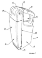
- a portable lighting device 10 has a body 12 of generally elongate rectilinear form. As will be noted for example, from figures 5 and6, the body is generally rectangular in the plan view.
- the body 12 has a base 14 which is flat and on which the lighting device 10 is adapted to be stood whilst in use as a table top lantern or the like.
- a battery cover moulding 16 forms part of the base and is removable to replace a battery cartridge indicated by dotted lines at 18. It is envisaged that the cartridge will contain 6"D cell"dry cell batteries.
- the body 12 has a light housing 20 connected thereto by a pivotal connection 22 located at the upper end of the body.
- the pivotal connection 22 will be described in moredetailed here below.
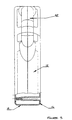
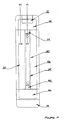
- the light housing 20 is made from a translucent central portion 24 which is formed of a front cover 26 and a rear cover 28 which are welded together along weld line 30.
- An elongate light source 32' is provided in the form of a tubular translucent lens 32 mounted within the light housing 20 and a pair of incandescent lamps 34 located in opposite ends of the tubular lens 32.
- the tubular lens 32 thus has the appearance of a longitudinal fluorescent lamp but, in fact, lighting is provided by the two incandescent lamps 34.
- the light housing 20 also includes a lower end portion 36 and an upper end portion 38 which houses the pivotal connection 22.
- the tubular lens 32 and incandescent lamps 34 of light source 32' can be replaced by a fluorescent lamp, providing appropriate lamp holders are installed.
- the incandescent lamps 24 can be replaced by one or more LEDs.
- a handle 40 is integrally formed with body12 and is located on the operative upper end of the lighting device.
- the handle 40 as is clear from Figure 3 is narrower than the rest of the body12. and defines an opening 42 into which a user'sfingers are received when carrying the lighting device 10.
- the handle 40 is inclined upwardly from the rear of the lighting device 10 towards the front thereof, the angle of inclination being approximately40 .
- the light emitted by the lamp 34 will project forwardly, and slightly downwardly, thereby providing a forwardly projecting light source 32'when the lighting device 10 is being carried in a comfortable position.
- the batteries used to power the lighting device 10 can be of considerable weight, therefore in order to make carrying the lighting device 10 more comfortable the handle 40 protrudes slightly from the back of the body 12. In combination with the acute angle of the handle the centre of mass of the lighting device 10 hangs beneath the hand of the carrier when the lighting device 10 is carried in a normal manner.
- the angle of the handle 40 can differ from 40 . and an angle of between30 and 60 is considered to provide the same characteristics.
- a switch 44 is located in the upper side of the handle 40 and is easily accessible by user's thumb for switching on and off the light source 32'.
- the switch 44 can be a three position slide switch, where there is provided two light sources, so that in a first position only one light source is in the closed circuit, and in a second position both light sources are in the closed circuit. The third position being an off position.
- the front face 48 of the front cover member 26 is of convex shape when viewed in side elevation, thatis, the Figure 1 view.
- This curved form of the cover 26 adds significantly to the strength of the light housing 20 and also serves to distribute light from the light source 32'in a more diffused manner.
- the curvature of the face 48 is arcuate, and the radius of curvature is relatively large, that is, significantly greater than the overall length of the body.
- the arcuate form of the cover 26 also serves to provide an aesthetically pleasing appearance to the lighting device 10.
- the pivotal connection 22 is shown in detail in figures 7 and 8.
- the body 12 includes a shaft 50 which spans across opposite sides thereof and provides a relatively rigid mounting axle to which the light housing 20 can connect.
- the light housing 20 is provided with a pair of straps 52 which passes around the shaft 50, as shown in Figure8. and are clamped around the shaft 50 by means of screws 54.
- the tightness of the grip of straps 52 around the shaft 50 can be varied by adjusting the screws 54.Further, by appropriately sizing the straps 52 and shaft 50, the straps 52 and shaft 50 will yield a relatively similar magnitude of friction when assembled in the lighting device 10 on a production or assembly line.
- It is desirable that the light housing 20 is able to pivot to any selected position through an arc of approximately270 . This allows the lighting device 10 to be stood on its base 14 and the light housing 20 can be pivoted away from the body 12 to any selected position.
- the light housing20 when standing vertically up away from the body 12 will distribute light in the substantially360 arc, much in the manner of a candle.
- the light housing 20 can be positioned at right angles to the length of the body 12 so that the light serves as a reading light or the like. It is envisaged that during assembly the screws 54 will be adjusted so that the frictional grip of the straps 52 around the shaft 50 will be optimised to allow for relatively easy pivoting of the light housing 20 relative to the body 12, yet the light housing 20 will maintain its position relative to the body 12 in any selected position of arc to which it is pivoted.
- the lighting device 10 need not take the overall form as has been disclosed herein although the form with a device depicted in the drawings is considered advantageous for the reasons outlined above. It is envisaged that the lighting device 10 will be relatively simple to manufacture, and therefore relativelyinexpensive. and yet will be not only robust but also able to be used in a number of different ways which adds significantly to the versatility of the lighting device 10.
- a friction device in the form of straps52 and shaft 50 is preferably utilised, a rotating engagement means which will allow indexed rotational motion such as a ratchet device could be used.
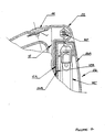
- Illustrated in Figure 9 is the light housing 26 shown in an elevated position relative to the body 12. In this position, the side 12A of body 12 is visible and the presence of a rectangular reflector 12B is noted.
- the reflector 12B ensures that the full visible spectrum of light generated from the light source 32'in the light housing 20 will be reflected off the body side 12A ensuring maximum usable light by preventing a substantial amount of visible light being absorbed by the body side 12A.
- the reflector 12B can be a highly polished sheet material, silvered, white or other highly reflective sheet material. which can be a metal plastic or coated plastic.
- the sheet material is preferably captured between the left and right halves of the body 12, or it can be adhered to the side 12A, or otherwise attached thereto.
- the reflector 12B can be a white plasticsticker.
- a side 26A (see figures 7 & 9) being that side which is outwardly directed when the light housing 20 is adjacent the body side 12A, is constructed from a frosted or translucent lens, while the opposite side 26B is constructed from a clear or transparent lens.
- a side 26A is constructed from a frosted or translucent lens
- the opposite side 26B is constructed from a clear or transparent lens. This ensures that when the light source 32'in light housing 20 is switched on. the reflector 12B will, due to the transparent nature of side 26B, receive a greater degree of light, which when reflected will pass back through side 26B, thus resulting in a more efficient transmission of light through side 26A. This can be particularly helpful if the lighting device 10 is being used for reading purposes. While the frosted and clear finishes cannot be illustrated, it will be seen from Figure 7 that 26A & 26B have different crosshatching in cross section illustrated.
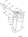
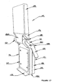
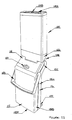
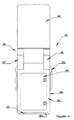
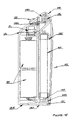
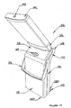
- FIG. 10 to 21 Illustrated in Figures 10 to 21 is a lighting device in the form of a lantern 102 which has a generally rectangular lens assembly or light housing 104 which is rotatably connected to a generally rectangular body 106 by a pivot assembly 108.
- the lantern 102 of Figure 10 illustrates the light housing 104 in an extended position whilst Figures 12, 13 and 15 illustrate the light housing in retracted position relative to the body 106.
- the body 106 is of a generally rectangular construction having a front face 110, a rear face 112 and left and right sides 114 and 116.
- the pivot assembly 108 is formed by two angled extensions 118 and 120 which extend away from the body 106 at approximately 45 to the vertical but an angle in the range of 15 to 60 can be utilised.
- the light housing 104 is illustrated in a vertical orientation which together with the assistance of a foot 122 ensures that the centre of gravity of light housing 104 is located between the forward extremity 122A of the foot 122 and the rearward extremity 122D of the base 122D.
- the mass of the dry cells and the body 106 being greater than the mass of the light housing 104 ensures that tipping will not occur.
- a rotatable handle 123 is captured between half 106A and other half 106B of the body 106 and can rotate from a position adjacent the side 112, until it engages the light housing 104. Thus the position of the light housing 104 determines the limits of rotation of handle 123.
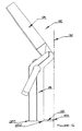
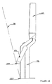
- the pivot assembly 108 cooperates with the forward extremity 122A of the foot 122 so that when the light housing 104 is rotated to its furthest most rotational position as illustrated in Figure 16, the lantern 102 can be placed on a surface of a table or other horizontal surface (generally represented by the axis 130) forming a three leg arrangement which will maintain the body 106 in a stable orientation with the light housing 104 being at an angle above the axis 130 (the axis 130 being representative of a generally horizontal surface).
- the handle 123 can cooperate with the rearward extremity 122D as illustrated in Figure 18 so as to rest the body 106 on rearward extremity 122D and edge 123A of handle 123 onto a surface generally represented by phantom line 130.
- the lantern 102 will have sufficient mass in body 106 to produce a moment of greater magnitude around 123A of handle 123 by comparison to the moment produced by the light housing 104 and the upper body portions including pivot assembly 108 around the same point. This arrangement allows a highly flexible and variable arrangement which can be utilised to obtain high degrees of stability for a user.
- the lantern 102 includes an on/off switch 124 on the body 106 while the light housing 104 includes an access panel 104A which utilises a screw 104B to secure the lens on the light housing 104 to the lens carrier 126.
- a cover 104C as illustrated in Figure 17 which is comprised of 5 sides can provide the terminus of the light housing 104.
- the lantern 102 has the lens housing 104 adjacent to the body 106.
- an access panel 128 is provided on the forward face 110 of the body 106 so that a user of the lantern 102 can gain access to the battery compartment for replacement or installation of dry cell batteries.
- the access panel 128 is manufactured from a highly reflective material such as silvered polymeric material, reflective metal or plastic material, or white painted or white coloured material. This ensures that when the lantern 102 has the light housing 104 in the retracted position of Figure 12 and the light source is switched on, light generated from the light housing 102 emitted in the direction of the body 106 will be reflected, in the main. by panel 128 back out through the light housing 104. This ensures that in the retracted orientation the lantern 102 can be stood on a table and generate sufficient light to enable reading or other activity.
- Another feature of the lantern 102 is that the light housing 104. when rotated to a vertical or over centre position as illustrated in Figure16, generates light in a360 circle around the longitudinal axis of the light housing 104 and acting in much the same manner as a candle.
- the cross section through the lantern 102 shows that the pivot assembly 108 includes a pivot clamp 108A which is secured to the body 106 by means of a friction screw 108B.
- the torque applied to friction screw 108B will determine the level of friction that the pivot clamp 108A will exert onto the spigot or shaft108C which isintegrally formed with or secured to the lens housing 126 in the reduced portion 126A.
- the pivot clamp 108A allows the lens carrier 126 and light housing 104 to be positioned at any location between the limits of travel of the lens carrier 126. and to hold the lens carrier 126 in that position without any outside assistance.
- the pivot clamp 108A is able to do this by means of the friction generated with the spigot or shaft108C.
- the lens carrier 126 includes a fluorescent tube and electrical connection support 135 while the cover plate 104A or cover104C has appropriate sockets to receive the terminals 137 of the fluorescent lamps and to electrically connect these ends so that current will flow through both fluorescent tubes.
- a printed circuit board 141 is included at the top of the body 106 with suitable wires and controls to the on/off switch 124 on the upper surface of the body 106 in the vicinity of the pivot assembly 108.
- Illustrated in figures 19 and 20 is an additional feature which can be utilised to provide greater efficiency of the light housing 104 and provide a greater range of options available to the user.
- a rotating reflector plate128A which if used removes the need to provide access panel 128 with the ability to reflect white light. Thatis, the panel 128 will not need to reflect white light.
- the rotating reflector 128A is manufactured from a sheet material which has a face 128B capable of reflecting the visible lightspectrum.
- the reflective material can be anyone of the currently available range of reflective material such aspolished, silvered, coated or white sheet materials which can be of metal or plastic as desired.
- the other side 128C can have the same reflective preparation, but is not preferred.
- the reflector 128A has two mounting limbs 128D and 128E bent or attached to right angles to the face 128B.
- the limbs 128D and 128E have coaxial apertures therethrough which are captured in the pivot assembly 108. This mounting arrangement allows the reflector 128A to be rotated simultaneously with the light housing 104 or at any time after if desired.
- the reflector 128A can be rotated so as to lie adjacent thereto, thus ensuring greater efficiency of light housing 104 to emit light in the downward and rearward direction relative to the body 106.
- a similar effect results when the light housing 104 and the reflector 128 are both in the retracted position.
- FIG 21 Illustrated in Figure 21 is a cross section similar to that of Figure 15, with like parts being is similar to that described above with respect to Figures 1 and 4.
- Another alternative light source which could be utilised is a cold cathode fluorescent lamp being approximately 3 to 6 mm in diameter.
Landscapes
- Engineering & Computer Science (AREA)
- General Engineering & Computer Science (AREA)
- Non-Portable Lighting Devices Or Systems Thereof (AREA)
- Sewing Machines And Sewing (AREA)
- Led Device Packages (AREA)
- Fastening Of Light Sources Or Lamp Holders (AREA)
- Organic Low-Molecular-Weight Compounds And Preparation Thereof (AREA)
- Arrangement Of Elements, Cooling, Sealing, Or The Like Of Lighting Devices (AREA)
Applications Claiming Priority (3)
| Application Number | Priority Date | Filing Date | Title |
|---|---|---|---|
| AUPQ1214A AUPQ121499A0 (en) | 1999-06-25 | 1999-06-25 | Portable lighting device |
| AUPQ1442A AUPQ144299A0 (en) | 1999-07-06 | 1999-07-06 | A mult-purpose lantern |
| EP00940016A EP1196718B1 (de) | 1999-06-25 | 2000-06-23 | Lanterneuanordnung |
Related Parent Applications (1)
| Application Number | Title | Priority Date | Filing Date |
|---|---|---|---|
| EP00940016A Division EP1196718B1 (de) | 1999-06-25 | 2000-06-23 | Lanterneuanordnung |
Publications (3)
| Publication Number | Publication Date |
|---|---|
| EP1617138A2 true EP1617138A2 (de) | 2006-01-18 |
| EP1617138A3 EP1617138A3 (de) | 2006-06-14 |
| EP1617138B1 EP1617138B1 (de) | 2009-02-11 |
Family
ID=25646083
Family Applications (2)
| Application Number | Title | Priority Date | Filing Date |
|---|---|---|---|
| EP05021585A Expired - Lifetime EP1617138B1 (de) | 1999-06-25 | 2000-06-23 | Laternenanordnung |
| EP00940016A Revoked EP1196718B1 (de) | 1999-06-25 | 2000-06-23 | Lanterneuanordnung |
Family Applications After (1)
| Application Number | Title | Priority Date | Filing Date |
|---|---|---|---|
| EP00940016A Revoked EP1196718B1 (de) | 1999-06-25 | 2000-06-23 | Lanterneuanordnung |
Country Status (5)
| Country | Link |
|---|---|
| EP (2) | EP1617138B1 (de) |
| CN (2) | CN1130512C (de) |
| AT (2) | ATE422648T1 (de) |
| DE (1) | DE60041560D1 (de) |
| WO (1) | WO2001001039A1 (de) |
Cited By (1)
| Publication number | Priority date | Publication date | Assignee | Title |
|---|---|---|---|---|
| EP3691231A1 (de) * | 2019-02-01 | 2020-08-05 | Panasonic Intellectual Property Management Co., Ltd. | Funktionsmodul |
Families Citing this family (11)
| Publication number | Priority date | Publication date | Assignee | Title |
|---|---|---|---|---|
| ATE425415T1 (de) | 2001-04-09 | 2009-03-15 | Eveready Battery Inc | Verbesserte beleuchtungsvorrichtung |
| DE102005021429A1 (de) * | 2004-08-05 | 2006-02-23 | John Mfg. Ltd., Kwun Tong Kowloon | Wiederaufladbares Halogen-Suchlicht |
| FR2877420B1 (fr) * | 2004-10-29 | 2007-05-18 | Ad Hoc Design Sarl | Dispositif d'eclairage de forme spherique |
| US20100067222A1 (en) * | 2006-12-22 | 2010-03-18 | Tai Pang Ng | Mountain Climbing Stick with Illuminating Device |
| US9845940B2 (en) | 2012-06-11 | 2017-12-19 | Energizer Brands, Llc | Lighting device and light panel construction |
| WO2013188276A2 (en) | 2012-06-11 | 2013-12-19 | Eveready Battery Company, Inc | A lighting device construction |
| WO2015135220A1 (en) * | 2014-03-14 | 2015-09-17 | Black & Decker Inc | Portable lighting apparatus |
| JP6876950B2 (ja) * | 2016-08-30 | 2021-05-26 | パナソニックIpマネジメント株式会社 | 照明器具 |
| CN109630955B (zh) * | 2019-01-17 | 2024-07-30 | 欧普照明股份有限公司 | 一种夜灯 |
| US11859783B2 (en) | 2020-06-15 | 2024-01-02 | Good Bison | Convertible light device |
| US11408568B2 (en) * | 2020-06-15 | 2022-08-09 | Good Bison | Convertible light device |
Family Cites Families (24)
| Publication number | Priority date | Publication date | Assignee | Title |
|---|---|---|---|---|
| GB882963A (en) * | 1959-12-08 | 1961-11-22 | Wing Gee Cheng | Improvements in or relating to electric lanterns or torches |
| US3767911A (en) * | 1972-11-13 | 1973-10-23 | Esb Inc | Battery powered electric lantern |
| US3875397A (en) * | 1974-04-15 | 1975-04-01 | Thomas H Nicholl | Means for producing colored light |
| AU067336S (en) * | 1975-07-10 | Foster Ind Co Ltd | Portable fluorescent lantern | |
| US4231077A (en) * | 1977-12-27 | 1980-10-28 | Joyce James E | Light toy |
| JPS5923281Y2 (ja) * | 1980-02-18 | 1984-07-11 | 九州日立マクセル株式会社 | 螢光ランタン |
| US4535392A (en) * | 1984-02-02 | 1985-08-13 | Montgomery William J I | Personal alert signal |
| JPS6132302A (ja) * | 1984-07-20 | 1986-02-15 | 松下電器産業株式会社 | 携帯用螢光灯 |
| SU1416794A1 (ru) * | 1986-10-04 | 1988-08-15 | Предприятие П/Я В-8624 | Герметичный осветительный прибор |
| JPS63285801A (ja) * | 1987-05-19 | 1988-11-22 | 日立照明株式会社 | 携帯用蛍光灯器具 |
| GB2238861B (en) * | 1989-12-05 | 1993-03-10 | Fatia Ind Co Ltd | Portable battery operated lighting device |
| GB2248292B (en) * | 1990-09-28 | 1993-09-15 | John Mfg Ltd | Combined incandescent/fluorescent lantern |
| US5243507A (en) * | 1992-07-27 | 1993-09-07 | Atkins Donald W | Portable quartz floodlight fixture |
| GB2273268A (en) * | 1992-12-09 | 1994-06-15 | Chuang Yi Chen | Retractable illuminating pen. |
| US5301093A (en) * | 1992-12-21 | 1994-04-05 | Woodhead Industries, Inc. | Fluorescent handlamp |
| US5535107A (en) * | 1994-12-20 | 1996-07-09 | Eveready Battery Company, Inc. | Combination gas recombination/venting means for portable lighting device |
| BR9500170A (pt) * | 1995-01-13 | 1995-07-11 | De Albuquerque Michel E Saboya | Aparelho para esterilizar superfície |
| US5595441A (en) * | 1995-02-23 | 1997-01-21 | Mcgee; David I. | Portable safety lighting device and method for increasing visibility of a person or vehicle |
| JPH08329707A (ja) * | 1995-05-31 | 1996-12-13 | Matsushita Electric Works Ltd | 照明器具 |
| US5595436A (en) * | 1995-11-17 | 1997-01-21 | Diamondlight Industries, Inc. | Flashlight with articulating stand |
| GB2324854A (en) * | 1997-05-02 | 1998-11-04 | John Mfg Ltd | Lantern |
| USD418237S (en) * | 1998-01-06 | 1999-12-28 | John Manufacturing Limited | Multi-function fluorescent lantern |
| GB2341228B (en) * | 1998-09-03 | 2002-05-22 | John Mfg Ltd | A combined incandescent/fluorescent lantern |
| AU140167S (en) * | 1999-05-03 | 2000-03-24 | Eveready Battery Inc | A lighting device |
-
2000
- 2000-06-23 WO PCT/AU2000/000720 patent/WO2001001039A1/en not_active Ceased
- 2000-06-23 CN CN00809420A patent/CN1130512C/zh not_active Expired - Fee Related
- 2000-06-23 EP EP05021585A patent/EP1617138B1/de not_active Expired - Lifetime
- 2000-06-23 AT AT05021585T patent/ATE422648T1/de not_active IP Right Cessation
- 2000-06-23 EP EP00940016A patent/EP1196718B1/de not_active Revoked
- 2000-06-23 AT AT00940016T patent/ATE533009T1/de active
- 2000-06-23 CN CNB03121679XA patent/CN1274990C/zh not_active Expired - Fee Related
- 2000-06-23 DE DE60041560T patent/DE60041560D1/de not_active Expired - Lifetime
Cited By (1)
| Publication number | Priority date | Publication date | Assignee | Title |
|---|---|---|---|---|
| EP3691231A1 (de) * | 2019-02-01 | 2020-08-05 | Panasonic Intellectual Property Management Co., Ltd. | Funktionsmodul |
Also Published As
| Publication number | Publication date |
|---|---|
| CN1515820A (zh) | 2004-07-28 |
| EP1196718A1 (de) | 2002-04-17 |
| DE60041560D1 (de) | 2009-03-26 |
| ATE422648T1 (de) | 2009-02-15 |
| WO2001001039A1 (en) | 2001-01-04 |
| EP1196718B1 (de) | 2011-11-09 |
| CN1274990C (zh) | 2006-09-13 |
| CN1130512C (zh) | 2003-12-10 |
| EP1617138A3 (de) | 2006-06-14 |
| ATE533009T1 (de) | 2011-11-15 |
| CN1358263A (zh) | 2002-07-10 |
| EP1196718A4 (de) | 2004-10-20 |
| EP1617138B1 (de) | 2009-02-11 |
Similar Documents
| Publication | Publication Date | Title |
|---|---|---|
| US8764253B2 (en) | Hands-free multi-positional task light and method of use thereof | |
| US8356908B1 (en) | Rotatable dual magnification mirror with internal hoop illuminator and movable reflector ring | |
| US5077644A (en) | Reflector for hand held flashlight | |
| EP1617138B1 (de) | Laternenanordnung | |
| US5558430A (en) | Dual beam flashlight | |
| US8162502B1 (en) | Illuminated continuously rotatable dual magnification mirror | |
| US6866395B2 (en) | Portable light having flexibly branched arms with LEDs | |
| US20140126192A1 (en) | Worklight with integrated clamp handle | |
| WO2024148931A1 (zh) | 纵握灯具、可调焦式手枪型聚光灯以及旋转挂钩枪灯 | |
| US20060146523A1 (en) | Fluorescent flood light | |
| GB2341228A (en) | Combined incandescent/fluorescent lantern with pivoting lighting arms | |
| US20110273887A1 (en) | Light for outdoor grill | |
| CN201425164Y (zh) | 多用途led灯 | |
| US7195371B2 (en) | Pocket flashlight apparatus | |
| US20120300438A1 (en) | Folding spotlight | |
| US4638413A (en) | Combination spotlight and table lamp | |
| CN104471304A (zh) | 具有集成的夹钳手柄的灯具 | |
| AU781240B2 (en) | A lantern construction | |
| JP3113977U (ja) | 携帯用の多用途光電子探照灯 | |
| CN1793716B (zh) | 手提式照明装置 | |
| US20030146706A1 (en) | Headlamp | |
| CN202834785U (zh) | 一种工作灯 | |
| CN212719268U (zh) | 一种双头工作灯 | |
| CN220669217U (zh) | 一种对讲概念台灯 | |
| CN216158866U (zh) | 折叠灯 |
Legal Events
| Date | Code | Title | Description |
|---|---|---|---|
| PUAI | Public reference made under article 153(3) epc to a published international application that has entered the european phase |
Free format text: ORIGINAL CODE: 0009012 |
|
| 17P | Request for examination filed |
Effective date: 20051004 |
|
| AC | Divisional application: reference to earlier application |
Ref document number: 1196718 Country of ref document: EP Kind code of ref document: P |
|
| AK | Designated contracting states |
Kind code of ref document: A2 Designated state(s): AT BE CH CY DE DK ES FI FR GB GR IE IT LI LU MC NL PT SE |
|
| AX | Request for extension of the european patent |
Extension state: AL LT LV MK RO SI |
|
| PUAL | Search report despatched |
Free format text: ORIGINAL CODE: 0009013 |
|
| AK | Designated contracting states |
Kind code of ref document: A3 Designated state(s): AT BE CH CY DE DK ES FI FR GB GR IE IT LI LU MC NL PT SE |
|
| AX | Request for extension of the european patent |
Extension state: AL LT LV MK RO SI |
|
| 17Q | First examination report despatched |
Effective date: 20060824 |
|
| AKX | Designation fees paid |
Designated state(s): AT BE CH CY DE DK ES FI FR GB GR IE IT LI LU MC NL PT SE |
|
| GRAP | Despatch of communication of intention to grant a patent |
Free format text: ORIGINAL CODE: EPIDOSNIGR1 |
|
| GRAS | Grant fee paid |
Free format text: ORIGINAL CODE: EPIDOSNIGR3 |
|
| GRAA | (expected) grant |
Free format text: ORIGINAL CODE: 0009210 |
|
| AC | Divisional application: reference to earlier application |
Ref document number: 1196718 Country of ref document: EP Kind code of ref document: P |
|
| AK | Designated contracting states |
Kind code of ref document: B1 Designated state(s): AT BE CH CY DE DK ES FI FR GB GR IE IT LI LU MC NL PT SE |
|
| REG | Reference to a national code |
Ref country code: GB Ref legal event code: FG4D |
|
| REG | Reference to a national code |
Ref country code: CH Ref legal event code: EP |
|
| REG | Reference to a national code |
Ref country code: IE Ref legal event code: FG4D |
|
| REF | Corresponds to: |
Ref document number: 60041560 Country of ref document: DE Date of ref document: 20090326 Kind code of ref document: P |
|
| PG25 | Lapsed in a contracting state [announced via postgrant information from national office to epo] |
Ref country code: NL Free format text: LAPSE BECAUSE OF FAILURE TO SUBMIT A TRANSLATION OF THE DESCRIPTION OR TO PAY THE FEE WITHIN THE PRESCRIBED TIME-LIMIT Effective date: 20090211 Ref country code: ES Free format text: LAPSE BECAUSE OF FAILURE TO SUBMIT A TRANSLATION OF THE DESCRIPTION OR TO PAY THE FEE WITHIN THE PRESCRIBED TIME-LIMIT Effective date: 20090522 |
|
| NLV1 | Nl: lapsed or annulled due to failure to fulfill the requirements of art. 29p and 29m of the patents act | ||
| PG25 | Lapsed in a contracting state [announced via postgrant information from national office to epo] |
Ref country code: SE Free format text: LAPSE BECAUSE OF FAILURE TO SUBMIT A TRANSLATION OF THE DESCRIPTION OR TO PAY THE FEE WITHIN THE PRESCRIBED TIME-LIMIT Effective date: 20090511 Ref country code: AT Free format text: LAPSE BECAUSE OF FAILURE TO SUBMIT A TRANSLATION OF THE DESCRIPTION OR TO PAY THE FEE WITHIN THE PRESCRIBED TIME-LIMIT Effective date: 20090211 |
|
| PG25 | Lapsed in a contracting state [announced via postgrant information from national office to epo] |
Ref country code: BE Free format text: LAPSE BECAUSE OF FAILURE TO SUBMIT A TRANSLATION OF THE DESCRIPTION OR TO PAY THE FEE WITHIN THE PRESCRIBED TIME-LIMIT Effective date: 20090211 |
|
| PG25 | Lapsed in a contracting state [announced via postgrant information from national office to epo] |
Ref country code: PT Free format text: LAPSE BECAUSE OF FAILURE TO SUBMIT A TRANSLATION OF THE DESCRIPTION OR TO PAY THE FEE WITHIN THE PRESCRIBED TIME-LIMIT Effective date: 20090713 Ref country code: DK Free format text: LAPSE BECAUSE OF FAILURE TO SUBMIT A TRANSLATION OF THE DESCRIPTION OR TO PAY THE FEE WITHIN THE PRESCRIBED TIME-LIMIT Effective date: 20090211 |
|
| PLBE | No opposition filed within time limit |
Free format text: ORIGINAL CODE: 0009261 |
|
| STAA | Information on the status of an ep patent application or granted ep patent |
Free format text: STATUS: NO OPPOSITION FILED WITHIN TIME LIMIT |
|
| 26N | No opposition filed |
Effective date: 20091112 |
|
| PG25 | Lapsed in a contracting state [announced via postgrant information from national office to epo] |
Ref country code: MC Free format text: LAPSE BECAUSE OF NON-PAYMENT OF DUE FEES Effective date: 20090630 |
|
| REG | Reference to a national code |
Ref country code: CH Ref legal event code: PL |
|
| REG | Reference to a national code |
Ref country code: IE Ref legal event code: MM4A |
|
| PG25 | Lapsed in a contracting state [announced via postgrant information from national office to epo] |
Ref country code: LI Free format text: LAPSE BECAUSE OF NON-PAYMENT OF DUE FEES Effective date: 20090630 Ref country code: CH Free format text: LAPSE BECAUSE OF NON-PAYMENT OF DUE FEES Effective date: 20090630 Ref country code: IE Free format text: LAPSE BECAUSE OF NON-PAYMENT OF DUE FEES Effective date: 20090623 |
|
| PG25 | Lapsed in a contracting state [announced via postgrant information from national office to epo] |
Ref country code: GR Free format text: LAPSE BECAUSE OF FAILURE TO SUBMIT A TRANSLATION OF THE DESCRIPTION OR TO PAY THE FEE WITHIN THE PRESCRIBED TIME-LIMIT Effective date: 20090512 |
|
| PG25 | Lapsed in a contracting state [announced via postgrant information from national office to epo] |
Ref country code: FI Free format text: LAPSE BECAUSE OF FAILURE TO SUBMIT A TRANSLATION OF THE DESCRIPTION OR TO PAY THE FEE WITHIN THE PRESCRIBED TIME-LIMIT Effective date: 20090211 |
|
| PG25 | Lapsed in a contracting state [announced via postgrant information from national office to epo] |
Ref country code: IT Free format text: LAPSE BECAUSE OF FAILURE TO SUBMIT A TRANSLATION OF THE DESCRIPTION OR TO PAY THE FEE WITHIN THE PRESCRIBED TIME-LIMIT Effective date: 20090211 |
|
| PG25 | Lapsed in a contracting state [announced via postgrant information from national office to epo] |
Ref country code: LU Free format text: LAPSE BECAUSE OF NON-PAYMENT OF DUE FEES Effective date: 20090623 |
|
| PG25 | Lapsed in a contracting state [announced via postgrant information from national office to epo] |
Ref country code: CY Free format text: LAPSE BECAUSE OF FAILURE TO SUBMIT A TRANSLATION OF THE DESCRIPTION OR TO PAY THE FEE WITHIN THE PRESCRIBED TIME-LIMIT Effective date: 20090211 |
|
| REG | Reference to a national code |
Ref country code: FR Ref legal event code: PLFP Year of fee payment: 16 |
|
| PGFP | Annual fee paid to national office [announced via postgrant information from national office to epo] |
Ref country code: DE Payment date: 20150629 Year of fee payment: 16 Ref country code: GB Payment date: 20150629 Year of fee payment: 16 |
|
| PGFP | Annual fee paid to national office [announced via postgrant information from national office to epo] |
Ref country code: FR Payment date: 20150617 Year of fee payment: 16 |
|
| REG | Reference to a national code |
Ref country code: DE Ref legal event code: R082 Ref document number: 60041560 Country of ref document: DE Representative=s name: COHAUSZ & FLORACK PATENT- UND RECHTSANWAELTE P, DE Ref country code: DE Ref legal event code: R081 Ref document number: 60041560 Country of ref document: DE Owner name: ENERGIZER BRANDS, LLC (N.D.GES.D. STAATES DELA, US Free format text: FORMER OWNER: EVEREADY BATTERY CO., ST. LOUIS, MO., US |
|
| REG | Reference to a national code |
Ref country code: FR Ref legal event code: TP Owner name: ENERGIZER BRANDS, LLC, US Effective date: 20160115 |
|
| REG | Reference to a national code |
Ref country code: GB Ref legal event code: 732E Free format text: REGISTERED BETWEEN 20161117 AND 20161123 |
|
| REG | Reference to a national code |
Ref country code: DE Ref legal event code: R119 Ref document number: 60041560 Country of ref document: DE |
|
| GBPC | Gb: european patent ceased through non-payment of renewal fee |
Effective date: 20160623 |
|
| REG | Reference to a national code |
Ref country code: FR Ref legal event code: ST Effective date: 20170228 |
|
| PG25 | Lapsed in a contracting state [announced via postgrant information from national office to epo] |
Ref country code: DE Free format text: LAPSE BECAUSE OF NON-PAYMENT OF DUE FEES Effective date: 20170103 Ref country code: FR Free format text: LAPSE BECAUSE OF NON-PAYMENT OF DUE FEES Effective date: 20160630 |
|
| PG25 | Lapsed in a contracting state [announced via postgrant information from national office to epo] |
Ref country code: GB Free format text: LAPSE BECAUSE OF NON-PAYMENT OF DUE FEES Effective date: 20160623 |