EP1617092A2 - Linearführungslager - Google Patents
Linearführungslager Download PDFInfo
- Publication number
- EP1617092A2 EP1617092A2 EP05015342A EP05015342A EP1617092A2 EP 1617092 A2 EP1617092 A2 EP 1617092A2 EP 05015342 A EP05015342 A EP 05015342A EP 05015342 A EP05015342 A EP 05015342A EP 1617092 A2 EP1617092 A2 EP 1617092A2
- Authority
- EP
- European Patent Office
- Prior art keywords
- rolling
- circulating sleeve
- linear guide
- bearing apparatus
- circulating
- Prior art date
- Legal status (The legal status is an assumption and is not a legal conclusion. Google has not performed a legal analysis and makes no representation as to the accuracy of the status listed.)
- Granted
Links
Images

Classifications
-
- F—MECHANICAL ENGINEERING; LIGHTING; HEATING; WEAPONS; BLASTING
- F16—ENGINEERING ELEMENTS AND UNITS; GENERAL MEASURES FOR PRODUCING AND MAINTAINING EFFECTIVE FUNCTIONING OF MACHINES OR INSTALLATIONS; THERMAL INSULATION IN GENERAL
- F16C—SHAFTS; FLEXIBLE SHAFTS; ELEMENTS OR CRANKSHAFT MECHANISMS; ROTARY BODIES OTHER THAN GEARING ELEMENTS; BEARINGS
- F16C29/00—Bearings for parts moving only linearly
- F16C29/04—Ball or roller bearings
- F16C29/06—Ball or roller bearings in which the rolling bodies circulate partly without carrying load
- F16C29/0633—Ball or roller bearings in which the rolling bodies circulate partly without carrying load with a bearing body defining a U-shaped carriage, i.e. surrounding a guide rail or track on three sides
- F16C29/0635—Ball or roller bearings in which the rolling bodies circulate partly without carrying load with a bearing body defining a U-shaped carriage, i.e. surrounding a guide rail or track on three sides whereby the return paths are provided as bores in a main body of the U-shaped carriage, e.g. the main body of the U-shaped carriage is a single part with end caps provided at each end
- F16C29/065—Ball or roller bearings in which the rolling bodies circulate partly without carrying load with a bearing body defining a U-shaped carriage, i.e. surrounding a guide rail or track on three sides whereby the return paths are provided as bores in a main body of the U-shaped carriage, e.g. the main body of the U-shaped carriage is a single part with end caps provided at each end with rollers
-
- F—MECHANICAL ENGINEERING; LIGHTING; HEATING; WEAPONS; BLASTING
- F16—ENGINEERING ELEMENTS AND UNITS; GENERAL MEASURES FOR PRODUCING AND MAINTAINING EFFECTIVE FUNCTIONING OF MACHINES OR INSTALLATIONS; THERMAL INSULATION IN GENERAL
- F16C—SHAFTS; FLEXIBLE SHAFTS; ELEMENTS OR CRANKSHAFT MECHANISMS; ROTARY BODIES OTHER THAN GEARING ELEMENTS; BEARINGS
- F16C29/00—Bearings for parts moving only linearly
- F16C29/04—Ball or roller bearings
- F16C29/06—Ball or roller bearings in which the rolling bodies circulate partly without carrying load
- F16C29/0602—Details of the bearing body or carriage or parts thereof, e.g. methods for manufacturing or assembly
- F16C29/0609—Details of the bearing body or carriage or parts thereof, e.g. methods for manufacturing or assembly of the ends of the bearing body or carriage where the rolling elements change direction, e.g. end caps
-
- F—MECHANICAL ENGINEERING; LIGHTING; HEATING; WEAPONS; BLASTING
- F16—ENGINEERING ELEMENTS AND UNITS; GENERAL MEASURES FOR PRODUCING AND MAINTAINING EFFECTIVE FUNCTIONING OF MACHINES OR INSTALLATIONS; THERMAL INSULATION IN GENERAL
- F16C—SHAFTS; FLEXIBLE SHAFTS; ELEMENTS OR CRANKSHAFT MECHANISMS; ROTARY BODIES OTHER THAN GEARING ELEMENTS; BEARINGS
- F16C29/00—Bearings for parts moving only linearly
- F16C29/04—Ball or roller bearings
- F16C29/06—Ball or roller bearings in which the rolling bodies circulate partly without carrying load
- F16C29/0602—Details of the bearing body or carriage or parts thereof, e.g. methods for manufacturing or assembly
- F16C29/0611—Details of the bearing body or carriage or parts thereof, e.g. methods for manufacturing or assembly of the return passages, i.e. the passages where the rolling elements do not carry load
-
- F—MECHANICAL ENGINEERING; LIGHTING; HEATING; WEAPONS; BLASTING
- F16—ENGINEERING ELEMENTS AND UNITS; GENERAL MEASURES FOR PRODUCING AND MAINTAINING EFFECTIVE FUNCTIONING OF MACHINES OR INSTALLATIONS; THERMAL INSULATION IN GENERAL
- F16C—SHAFTS; FLEXIBLE SHAFTS; ELEMENTS OR CRANKSHAFT MECHANISMS; ROTARY BODIES OTHER THAN GEARING ELEMENTS; BEARINGS
- F16C41/00—Other accessories, e.g. devices integrated in the bearing not relating to the bearing function as such
- F16C41/008—Identification means, e.g. markings, RFID-tags; Data transfer means
Definitions
- the present invention relates to a linear guide bearing apparatus for use in, for example, industrial machines.
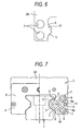
- an apparatus shown in FIG. 7 is known as a related linear guide bearing apparatus of such a kind (see, for instance, Patent Document 1).
- This linear guide bearing apparatus has a guide rail 1 extending in an axial direction, and a slider 2 bridged across the guide rail 1 to be able to be displaced with respect thereto in the axial direction.
- Two rows of rolling-element rolling grooves 3 extending in the axial direction are formed in each of both widthwise side surfaces of the guide rail 1, so that a total of four rolling-element rolling grooves 3 are formed.
- Rolling-element rolling grooves 5 respectively opposed to the rolling-element rolling grooves 3 are formed in the inner side surfaces of both sleeve portions 4 of the slider body 2A of the slider 2. These rolling-element rolling grooves 3 and 5 constitute a load raceway.
- rollers 6 serving as rolling elements are rollably loaded into the load raceway. Rolling of the rollers 6 enables the slider 2 to be displaced on the guide rail 1 in the axial direction with respect thereto.
- the direction change path 10 communicating between the upper rolling-element path 8a and each of both the lower rolling-element rolling grooves 3 and 5 is disposed to cross the direction change path 10, which communicates between the lower rolling-element path 8a and each of both the upper rolling-element rolling grooves 3 and 5, in a grade separation manner.
- Patent Document 1 JP-A-2002-54633.
- the rolling element path 8a of each of the circulating sleeves 8 fitted into the holes 7 of the slider body 2A is a path for the cylindrical roller 8 and is cross-sectionally rectangular.
- An object of the invention is to provide a linear guide bearing apparatus enabled to easily achieve an operation of adjusting the phase of the circulating sleeves and also enabled to smoothly perform assembly thereof.
- a linear guide bearing apparatus including a guide rail, which has a rolling element rolling groove axially extends, and a slider, which has a rolling element rolling groove opposed to the rolling element rolling groove of the guide rail and is bridged across the guide rail to be able to be axially displaced with respect thereto by rolling a large number of rollers serving rolling elements, and which are inserted into a load raceway formed between the rolling element rolling grooves.
- the slider includes a slider body, in which a circulating sleeve is fitted into each of holes axially penetrating therethrough and has an inner part used as a rolling element path, and an end cap that has a curved direction change path communicating between the load raceway and the rolling element path and that is fixed at an axial end portion of the slider body.
- the first aspect linear guide bearing apparatus features that a projecting portion extending along an axial end surface of the slider body is provided at least at one of the circulating sleeves.
- the linear guide bearing apparatus according to the first aspect, further including a concave portion, into which the projecting portion is fitted, provided in the end cap, wherein a phase of each of the circulating sleeves with respect to the slider body is adjusted by fitting the projecting portion into the concave portion.
- the linear guide bearing apparatus according to the first or second aspect, wherein the projecting portion constitutes a part of the direction change path.
- the linear guide bearing apparatus according to the first aspect, further including a concave portion provided in an axial end portion of the slider body, and a convex portion to be fitted into the concave portion provided on the projecting portion, wherein a phase of each of the circulating sleeves with respect to the slider body is adjusted by fitting the convex portion into the concave portion.
- the circulating sleeve with the projecting portion includes a first circulating sleeve constituent member and a second circulating sleeve constituent member, into which the circulating sleeve is split along a central axis thereof, and a color for discriminating between the first circulating sleeve constituent member and the second circulating sleeve constituent member is applied to at least one of the first circulating sleeve constituent member and the second circulating sleeve constituent member.
- a linear guide bearing apparatus including a guide rail, which has a rolling element rollinggroove axially extends, and a slider, which has a rolling element rolling groove opposed to the rolling element rolling groove of the guide rail and is bridged across the guide rail tobe able tobe axially displaced with respect thereto by rolling a large number of rollers serving rolling elements, and which are inserted into a load raceway formed between the rolling element rolling grooves.
- the sixth aspect linear guide bearing apparatus features that a color for discriminating paired components, which have obj ect shapes, among components of the linear guide bearing apparatus, is applied to at least one of the paired components.
- the torque causing the circulating sleeve to be fitted into the hole to rotate can be applied by utilizing the projecting portion. Consequently, the operation of adjusting the phase of the circulating sleeve can easily be performed.
- the second aspect linear guide bearing apparatus features that a concave portion, into which the projecting portion is fitted, is provided in the end cap, and that a phase of each of the circulating sleeves with respect to the slider body is adjusted by fitting the projecting portion into the concave portion, in addition to the features of the first aspect linear guide bearing apparatus of the invention.
- the phase of the circulating sleeve can easily be adjusted.
- the third aspect linear guide bearing apparatus of the invention features that the projecting portion constitutes a part of the direction change path, in addition to the features of the first or second aspect linear guide bearing apparatus of the invention.
- the number of the components can be reduced.
- the step-like parts in the circulating path, in which the rolling elements are circulated, are reduced. Consequently, the rolling elements can smoothly be passed therethrough.
- the fourth aspect linear guide bearing apparatus of the invention features that a concave portion is provided in an axial end portion of the slider body, that a convex portion to be fitted into the concave portion is provided on the projecting portion, and that a phase of each of the circulating sleeves with respect to the slider body is adjusted by fitting the convex portion into the concave portion, in addition to the features of the first aspect linear guide gearing apparatus of the invention.
- the phase of the circulating sleeve can easily be adjusted.
- the concave portion serves as a mark indicating the hole, into which the circulating sleeve is inserted, the circulating sleeve can be prevented from being inserted into the erroneous hole.
- the fifth aspect linear guide bearing apparatus of the invention features that a color for discriminating between the first circulating sleeve constituent member and the second circulating sleeve constituent member is applied to at least one of the first circulating sleeve constituent member and the second circulating sleeve constituent member, in addition to the feature of one of the first to fourth aspect linear guide bearing apparatuses.
- the first circulating sleeve constituent member and the second circulating sleeve constituent member can be discriminated from each other at a glance and also can be combined with each other.
- the sixth aspect linear guide bearing apparatus of the invention features that a color for discriminating paired components, which have object shapes, among components of the linear guide bearing apparatus, is applied to at least one of the paired components.
- the paired components of the linear guide bearing apparatus can be discriminated from each other at a glance and also can be combined with each other.
- FIG. 1 is an explanatory view illustrating a primary part of a linear guide bearing apparatus that is an embodiment of the invention.
- FIG. 2 is an explanatory view illustrating the configuration of a circulating sleeve shown in FIG. 1.
- FIG. 3 is a left side view illustrating the circulating sleeve shown in FIG. 1.
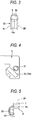
- FIG.4 is a view partly illustrating an end cap.
- FIG. 5 is an explanatory view illustrating a primary part of a linear guide bearing apparatus that is another embodiment of the invention.
- FIG. 6 is a view partly illustrating an axial end surface of a slider body.
- parts, which are the same as or correspond to those described by referring to FIG. 7, are designated by the same reference characters used in FIG. 7. Thus, the description of such parts is omitted herein.
- a linear guide bearing apparatus which is an embodiment of the invention, has a projectingportion 20 that is provided at an end portion of a circulating sleeve 8 and extends along an axial end surface of a slider body 2A.
- the circulating sleeve 8 including the projecting portion 20 is split along a central axis thereof into and comprises twoparts, that is, a first circulating sleeve constituent member 8R and a second circulating sleeve constituent member 8L.
- a positioning convex portion 11 and a positioning concave portion 12 are respectively formed at a position on the splitting surface of one of the first circulating sleeve constituent member 8R and the second circulating sleeve constituent member 8L, and at a position in that of the other sleeve constituent member so that the position of the convex portion 11 corresponds to the position of the concave portion 12 when the first circulating sleeve constituent member 8R and the second circulating sleeve constituent member 8L are fitted to each other.
- the circulating sleeve 8 is formed by superposing the splitting surfaces of first circulating sleeve constituent member 8R and the second circulating sleeve constituent member 8L so that the positioning convex portion 11, which is formed at a position on the splitting surface of one of the first circulating sleeve constituent member 8R and the second circulating sleeve constituent member 8L, is fitted into the positioning concave portion 12 formed in that of the other sleeve constituent member.
- a rolling element path 8a is formed in the circulating sleeve 8. During this state, the circulating sleeve 8 is inserted into a hole 7 of the slider body 2A.
- a color is applied to the entirety of at least one of the first circulating sleeve constituent member 8R and the second circulating sleeve constituent member 8L.
- This color enables that the first circulating sleeve constituent member 8R and the second circulating sleeve constituent member 8L can be discriminated from each other at a glance and also can be combined with each other.
- a method of applying a color thereto is to apply a color directly to each of the resinmaterials.
- the circulating sleeve constituent members 8R and 8L are formedofmetallicmaterials, and where it is difficult to apply a color directly to each of the metallic materials, the color may be applied to the members 8R and 8L by performing secondary processing, such as painting.
- an inner periphery side raceway 10a of a direction change path 10 is formed in the projecting portion 20 so as to reduce the number of components.
- the projecting portion 20 is fitted into this positioning concave portion 30 to thereby adjust the phase of the circulating sleeve 8 with respect to the hole 7 of the slider body 2A.
- the phase of the circulating sleeve 8 can easily be adjusted at fabrication of the apparatus.
- the projecting portion 20 is formed integrally with the inner periphery side raceway 10a of the direction change path 10.
- a projection 32 is provided at the other end portion of the circulating sleeve 8 so that the projection 32 is fitted into a hole 31 (see FIG. 4) provided in the opposite end cap 9.
- the circulating sleeve 8 is more firmly fixed by fitting the projection 32 into the hole 31.
- linear guide bearing apparatus of the invention is not limited to the aforementioned embodiment.
- the embodiment can appropriately be altered without departing from the spirit and scope of the invention.
- a convex portion 40 is provided on a side of the projecting portion 20 of the circulating sleeve 8, which faces an axial end surface of the slider body 2A.
- a concave portion 41 into which the convex portion 40 is fitted, is provided in the axial end surface of the slider body 2A. The phase of the circulating sleeve 8 with respect the hole 7 of the slider body 2A is adjusted by fitting the convex portion 40 into the concave portion 41.
- the concave portion 41 serves as a mark indicating the hole 7 (the lower one, as viewed in FIG. 6), into which the circulating sleeve 8 is inserted.
- the circulating sleeve 8 can be prevented from being inserted into the erroneous hole 7 (the upper one, as viewed in FIG. 6).
- the circulating sleeve 8 is inserted from an opposite side into the upper hole shown in FIG. 6.
- the convex portion 40 provided in the projecting portion 20 of the circulating sleeve 8 is fitted into the concave portion 41 of the slider body 2A.
- a color is applied to at least one of paired right circulating sleeve members 8R and 8L
- the invention is not limited to this case.
- a color is applied to at least one of paired components, which have symmetric shapes, among components of the linear guide bearing apparatus so as to discriminate the paired components from each other.
- the invention can obtain effects of smoothly performing the fabrication of the linear guide bearing apparatus. Additionally, it is unnecessary to apply the color to the entiretyof each of the components. Acolormaybe applied to positions or a range on a part of each of the components so that the components can easily and visually be checked.
Landscapes
- Engineering & Computer Science (AREA)
- General Engineering & Computer Science (AREA)
- Mechanical Engineering (AREA)
- Bearings For Parts Moving Linearly (AREA)
Applications Claiming Priority (1)
| Application Number | Priority Date | Filing Date | Title |
|---|---|---|---|
| JP2004207171 | 2004-07-14 |
Publications (3)
| Publication Number | Publication Date |
|---|---|
| EP1617092A2 true EP1617092A2 (de) | 2006-01-18 |
| EP1617092A3 EP1617092A3 (de) | 2011-03-23 |
| EP1617092B1 EP1617092B1 (de) | 2013-04-10 |
Family
ID=35044610
Family Applications (1)
| Application Number | Title | Priority Date | Filing Date |
|---|---|---|---|
| EP05015342.8A Expired - Lifetime EP1617092B1 (de) | 2004-07-14 | 2005-07-14 | Linearführungslager |
Country Status (2)
| Country | Link |
|---|---|
| US (1) | US20060034553A1 (de) |
| EP (1) | EP1617092B1 (de) |
Families Citing this family (1)
| Publication number | Priority date | Publication date | Assignee | Title |
|---|---|---|---|---|
| US20080292226A1 (en) * | 2007-05-22 | 2008-11-27 | Hiwin Technologies Corp. | Linear motion guide apparatus |
Citations (1)
| Publication number | Priority date | Publication date | Assignee | Title |
|---|---|---|---|---|
| JP2002054633A (ja) | 2000-05-29 | 2002-02-20 | Thk Co Ltd | 運動案内装置 |
Family Cites Families (17)
| Publication number | Priority date | Publication date | Assignee | Title |
|---|---|---|---|---|
| JPS61116120A (ja) * | 1984-11-13 | 1986-06-03 | Hiroshi Teramachi | 直線運動ロ−ラ−ベアリング |
| JPH0796893B2 (ja) * | 1987-03-12 | 1995-10-18 | 日本トムソン株式会社 | クロスローラ方式の無限直線運動用ころ軸受 |
| JPS6412129A (en) * | 1987-07-07 | 1989-01-17 | Hiihaisuto Seiko Kk | Linear motion guiding roller bearing |
| JP2865854B2 (ja) * | 1990-11-27 | 1999-03-08 | 日本トムソン株式会社 | 四条列無限直動案内ユニット |
| DE4111544A1 (de) * | 1991-04-09 | 1992-10-15 | Worm Hans Gmbh Co Kg | Kugelfuehrung |
| JP2575895Y2 (ja) * | 1992-10-12 | 1998-07-02 | 日本トムソン株式会社 | 直動転がり案内ユニット |
| JPH09177768A (ja) * | 1995-12-26 | 1997-07-11 | Ntn Corp | 機械構成部品の識別構造および識別方法 |
| EP1251287B1 (de) * | 1996-05-13 | 2006-04-26 | Thk Co. Ltd. | Linear Wälzführung |
| JPH10115316A (ja) * | 1996-10-09 | 1998-05-06 | Thk Kk | 転がり運動案内装置 |
| JP4118362B2 (ja) * | 1997-04-30 | 2008-07-16 | Thk株式会社 | 無限摺動用案内装置 |
| DE69913280T2 (de) * | 1998-04-09 | 2004-05-27 | Thk Co., Ltd. | Rollenverbindungsvorrichtung und diese verwendende linearführungseinrichtung |
| US6712511B2 (en) * | 2001-02-21 | 2004-03-30 | Nippon Thompson Co., Ltd. | Linear motion guide unit |
| US7121723B2 (en) * | 2003-04-11 | 2006-10-17 | Nsk Ltd. | Linear guide apparatus |
| US7578620B2 (en) * | 2003-10-21 | 2009-08-25 | Nsk Ltd. | Linear guide device |
| DE102004035211A1 (de) * | 2004-07-21 | 2006-02-16 | Ina-Schaeffler Kg | Linearführungseinheit |
| US7134790B2 (en) * | 2005-03-07 | 2006-11-14 | Hiwin Technologies Corp. | Recirculating apparatus of linear motion guiding |
| JP4307402B2 (ja) * | 2005-03-29 | 2009-08-05 | 日本トムソン株式会社 | 直動転がり案内ユニット |
-
2005
- 2005-07-13 US US11/179,774 patent/US20060034553A1/en not_active Abandoned
- 2005-07-14 EP EP05015342.8A patent/EP1617092B1/de not_active Expired - Lifetime
Patent Citations (1)
| Publication number | Priority date | Publication date | Assignee | Title |
|---|---|---|---|---|
| JP2002054633A (ja) | 2000-05-29 | 2002-02-20 | Thk Co Ltd | 運動案内装置 |
Also Published As
| Publication number | Publication date |
|---|---|
| US20060034553A1 (en) | 2006-02-16 |
| EP1617092A3 (de) | 2011-03-23 |
| EP1617092B1 (de) | 2013-04-10 |
Similar Documents
| Publication | Publication Date | Title |
|---|---|---|
| US8408803B2 (en) | Ultrathin cross-roller bearing | |
| GB2366349A (en) | Ball screw | |
| DE69929473T2 (de) | Lagersystem mit geräuschverminderung und axialer vorspannung | |
| DE102004018154A1 (de) | Zylinderrollenlager und Käfig für Zylinderrollenlager | |
| US5893646A (en) | Ball spline | |
| US10641316B2 (en) | Bearing sleeve for a shaft | |
| CN104334898A (zh) | 外筒被分割成三部分的直线运动轴承 | |
| US6688774B2 (en) | Mounting means | |
| EP1617092B1 (de) | Linearführungslager | |
| JPH1030638A (ja) | 曲動転がり案内ユニット | |
| JP4635735B2 (ja) | 直動案内軸受装置 | |
| CN113631820B (zh) | 内圈分离型角接触球轴承 | |
| CA1038434A (en) | Anti-friction ball bearing assembly | |
| KR20180051391A (ko) | 밀봉 구조 | |
| US20120213462A1 (en) | Needle roller bearing for a bearing arrangement | |
| US6099410A (en) | Linear-motion rolling guide unit with a flange cover | |
| JP3633245B2 (ja) | 複列転がり軸受装置 | |
| US20040120616A1 (en) | Linear guide device and method for designing or forming raceway groove thereof | |
| EP3869068B1 (de) | Kugelrollspindelvorrichtung | |
| JP2004293783A (ja) | 直動案内軸受装置 | |
| US7309162B2 (en) | Linear guide | |
| KR101631462B1 (ko) | 가이드 장치 | |
| JP5332626B2 (ja) | ボールスプライン | |
| JP2000257630A (ja) | リニアブッシュアセンブリー | |
| JP2020085123A (ja) | クロスローラ軸受 |
Legal Events
| Date | Code | Title | Description |
|---|---|---|---|
| PUAI | Public reference made under article 153(3) epc to a published international application that has entered the european phase |
Free format text: ORIGINAL CODE: 0009012 |
|
| AK | Designated contracting states |
Kind code of ref document: A2 Designated state(s): AT BE BG CH CY CZ DE DK EE ES FI FR GB GR HU IE IS IT LI LT LU LV MC NL PL PT RO SE SI SK TR |
|
| AX | Request for extension of the european patent |
Extension state: AL BA HR MK YU |
|
| RIC1 | Information provided on ipc code assigned before grant |
Ipc: F16C 33/58 20060101AFI20051013BHEP Ipc: F16C 29/06 20060101ALI20101123BHEP |
|
| PUAL | Search report despatched |
Free format text: ORIGINAL CODE: 0009013 |
|
| AK | Designated contracting states |
Kind code of ref document: A3 Designated state(s): AT BE BG CH CY CZ DE DK EE ES FI FR GB GR HU IE IS IT LI LT LU LV MC NL PL PT RO SE SI SK TR |
|
| AX | Request for extension of the european patent |
Extension state: AL BA HR MK YU |
|
| 17P | Request for examination filed |
Effective date: 20110923 |
|
| AKX | Designation fees paid |
Designated state(s): DE |
|
| 17Q | First examination report despatched |
Effective date: 20111221 |
|
| GRAP | Despatch of communication of intention to grant a patent |
Free format text: ORIGINAL CODE: EPIDOSNIGR1 |
|
| GRAS | Grant fee paid |
Free format text: ORIGINAL CODE: EPIDOSNIGR3 |
|
| GRAA | (expected) grant |
Free format text: ORIGINAL CODE: 0009210 |
|
| AK | Designated contracting states |
Kind code of ref document: B1 Designated state(s): DE |
|
| REG | Reference to a national code |
Ref country code: DE Ref legal event code: R096 Ref document number: 602005038957 Country of ref document: DE Effective date: 20130606 |
|
| PLBE | No opposition filed within time limit |
Free format text: ORIGINAL CODE: 0009261 |
|
| STAA | Information on the status of an ep patent application or granted ep patent |
Free format text: STATUS: NO OPPOSITION FILED WITHIN TIME LIMIT |
|
| 26N | No opposition filed |
Effective date: 20140113 |
|
| REG | Reference to a national code |
Ref country code: DE Ref legal event code: R097 Ref document number: 602005038957 Country of ref document: DE Effective date: 20140113 |
|
| PGFP | Annual fee paid to national office [announced via postgrant information from national office to epo] |
Ref country code: DE Payment date: 20240529 Year of fee payment: 20 |
|
| REG | Reference to a national code |
Ref country code: DE Ref legal event code: R071 Ref document number: 602005038957 Country of ref document: DE |