EP1616792A2 - A contents-filling vessel reversing apparatus and a vessel for use with the apparatus - Google Patents
A contents-filling vessel reversing apparatus and a vessel for use with the apparatus Download PDFInfo
- Publication number
- EP1616792A2 EP1616792A2 EP05015011A EP05015011A EP1616792A2 EP 1616792 A2 EP1616792 A2 EP 1616792A2 EP 05015011 A EP05015011 A EP 05015011A EP 05015011 A EP05015011 A EP 05015011A EP 1616792 A2 EP1616792 A2 EP 1616792A2
- Authority
- EP
- European Patent Office
- Prior art keywords
- vessel
- contents
- gripping members
- gripping
- stop position
- Prior art date
- Legal status (The legal status is an assumption and is not a legal conclusion. Google has not performed a legal analysis and makes no representation as to the accuracy of the status listed.)
- Granted
Links
Images
Classifications
-
- B—PERFORMING OPERATIONS; TRANSPORTING
- B65—CONVEYING; PACKING; STORING; HANDLING THIN OR FILAMENTARY MATERIAL
- B65B—MACHINES, APPARATUS OR DEVICES FOR, OR METHODS OF, PACKAGING ARTICLES OR MATERIALS; UNPACKING
- B65B1/00—Packaging fluent solid material, e.g. powders, granular or loose fibrous material, loose masses of small articles, in individual containers or receptacles, e.g. bags, sacks, boxes, cartons, cans, or jars
- B65B1/04—Methods of, or means for, filling the material into the containers or receptacles
- B65B1/06—Methods of, or means for, filling the material into the containers or receptacles by gravity flow
Definitions
- the present invention relates to a contents-filling vessel reversing apparatus for use in a bag packaging machine, namely an apparatus for reversing a vessel accommodating contents to be filled into a container such as, for example, a packaging bag. More specifically, the present invention relates to a contents-filling vessel reversing apparatus for reversing a vessel accommodating contents to be filled into a container from a upright state to an inverted state, thereby dropping downward and filling the contents into a packaging container disposed underneath, when foods or the like are packaged in the packaging container. The present invention also relates to a contents-filling vessel for accommodating contents to be filled into a packaging container which vessel are suitable for use with the contents-filling vessel reversing apparatus.
- a vessel is held by gripping members provided at one end of an rotating arm and the vessel is reversed from an upright state to an inversed state by rotating the arm by approximately 180 degrees, and the vessel still in a being accelerated state is released at this reversed position.
- the vessel is then hit and stopped by such as a stopper plate or the like to discharge the contents contained in the vessel downwardly. Therefore, a big impact noise is generated at hitting, thereby resulting in one of causes responsible for deteriorated working environments.
- the vessel may be chipped in part when hitting on the stopper, which may poses a problem that fragments generated are mixed into the packaging container (vessels made of resin are used in many cases).
- a cushion member made of, for example, rubber or the like is provided at the stopper portion.
- the impact noise is reduced to a certain extent, this attempt is still not deemed satisfactory.
- the rubber as the cushion member as well as the vessel are worn and in some cases, fragments are mixed into the contents to be filled.
- discharging of the contents from the vessel may become imperfect due to the cushioning action of the cushion member.
- the vessels usually have a smooth outer circumference, upper and lower end faces free from projections and depressions.
- engaging surfaces of a pair of gripping members for gripping the vessel is also formed smooth. Therefore, it is necessary to grip the vessel with a considerably strong force in order to prevent the vessel from slipping off from the gripping members when the vessel is reversed.
- a small portion of the contents may adhere onto the outer circumference of the vessel.
- the strength of the gripping force should be set at a higher level. Accordingly, wear of the vessel becomes excessive and durability becomes poor. Besides, there is a possibility that foreign matters generated by wear are mixed into the contents.
- the present invention is made in light of the problems with the prior art as mentioned above.
- the object of the present invention is to present a contents-filling vessel reversing apparatus capable of discharging the contents from the vessel without hitting it against a stopper or the like, thereby preventing generation of noises to realize favorable working environments, and in addition, avoiding breakage of the vessel and preventing entry of fragments of the vessel into the contents to be filled.
- Still another object of the present invention is to present a contents-filling vessel for accommodating contents to be filled into a packaging container which can be used favorably with the above-mentioned contents-filling vessel reversing apparatus.
- the gripping members grip a vessel and rotate, and when the gripping members stop at the reversal stop position, the vessel is in a reversed state and stopped, thereby discharging the contents in the vessel due to the inertia force.
- the empty vessel is still griped by the gripping members even after it is reversed and the contents is discharged, and is released towards the vessel carrying-out device on the way returning to the gripping stop position. Therefore, there is no direct collision of a vessel with a stopper plate as observed in the prior art and problems of chipping of vessels, entry of foreign matters into a packaging container and deterioration of working environments do not occur.
- the reversal stop position can be regulated to any desired position by the reversal stop position regulating device and, therefore, it is possible to regulate the reversal stop position according to properties and amount of the contents to be filled, processing rate or the like to ensure accurate dropping of the contents into a packaging container disposed directly underneath.
- the main rotating member comprises a main rotating shaft rotating intermittently in one direction every 180 degrees
- the rotating device further comprises a supporting shaft supported by the main rotating shaft in parallel to the main rotating shaft in an axial direction and designed to be reciprocally rotatable around an axis thereof between an initial position and a rotated position.
- the contents-filling vessel reversing apparatus further comprises a supporting shaft rotating device for rotating the supporting shaft.
- the reversing stop position regulating device regulates the rotated position of the supporting shaft, and the pair of gripping members are mounted on one end of the supporting shaft.
- the supporting shaft rotating device is designed to change the relative position of the supporting shaft to the main rotating shaft in the direction of rotation by turning the supporting shaft. Therefore, even when two sets of gripping members are provided and these are rotated intermittently every 180 degrees by the reversing device, it is possible to change the reversal stop position while the gripping stop position is fixed.
- the supporting shaft is rotated during the reversal operation.
- the way of rotating of the supporting shaft for example by not tilting the vessel greatly at the earlier stage of reversal and tilting the vessel rapidly and greatly at the last end stage of reversal, depending on type, properties, and amount of contents to be filled, it is possible to prevent the contents from flying out from the vessel at an stage earlier than desired.
- the supporting shaft is formed to be hollow
- the gripping member opening/closing device comprises a sliding shaft inserted into the hollow section of the supporting shaft and movable in the axial direction.
- the sliding shaft is connected at one end to the gripping members, and the gripping members are opened and closed interlockingly with the axial direction movement of the sliding shaft.
- peripheral arrangement of the reversal mechanism of the apparatus can be made compact, and ease of cleaning is improved.
- the supporting shaft rotating device is equipped with a grooved cam securely positioned with an axis thereof coinciding with the axis of said main rotating shaft, a lever fixed to the other end of said supporting shaft and a cam roller mounted on the lever so as to roll in and move along a groove formed in the grooved cam.
- a predetermined range in the groove extending in the opposite directions from a position corresponding to the rotated position of the supporting shaft, at least a radius of curvature of an inner wall of said groove is made shorter than a radius of curvature of the inner wall in a rest range in the groove so that a width of the groove in said predetermined range is larger than a width of the groove in the rest range.
- the reversal stop regulating device is provided with a positioning stopper which abuts against the lever to position the lever at the reversal stop position, and a stopper position regulating device for regulating the position of the stopper.
- compositions mentioned above it is possible to change the reversal stop position only by adjusting the position of the stopper, and the gripping stop position is unchanged even when the reversal stop position is changed. Therefore, the adjustment can be done easily.
- two supporting shafts are provided symmetrically with respect to the axis of the main rotating shaft, and each of the supporting shafts is provided with a pair of the gripping members. Therefore, it is possible to improve processing capability of the apparatus.
- the gripping members grip the vessel on the outer circumference thereof.
- the vessel is provided with a thin strip projection or a groove formed on the outer circumference and extending over the entire circumference of the vessel, while each of the gripping members is provided with a groove or a thin strip projection formed on the gripping face opposing to the vessel to engage with the thin strip projection or the groove on the vessel.
- projections or grooves having a nearly circular or trapezoidal section can make reliable and stable the engagement between the thin strip projection and the groove respectively provided on the vessel and gripping members. Besides, if a groove is formed on the vessel, breakage of the vessel due to collision of fellow thin strip projections of adjacent vessels as may be observed when the thin strip projection is formed on the vessel can be avoided.
- the rotational speed of the main rotating member changes with at least two steps mode.
- a low speed may be employed during a first movement stage when the gripping members move from the reversal stop position to the vessel discharging position, and a speed higher than that of the first movement stage may be employed during a second movement stage when the gripping member move later to the gripping stop position.
- the present invention presents a contents-filling vessel for accommodating contents to be filled for preferable use with the above-mentioned contents-filling vessel reversing apparatus.
- the vessel is provided with a groove or a thin strip projection formed on the outer circumference thereof and extending over the entire circumference thereof.
- the sectional profile of the groove or thin strip projection is nearly semicircular or trapezoidal in section.
- breakage of a vessel during operation can be prevented and entry of foreign matters into packaging containers can be prevented. Further, noise generation can be reduced, which contributes to improvement of working environments. Furthermore, it is possible to prevent the contents in the vessel from erroneously flying out from the vessel at an undesired stage during operation, and the contents can be dropped surely into a packaging container located directly below the reversal position. Adjustments for this purpose can easily be done.
- FIG. 1 is a partly sectioned front view showing a contents-filling vessel reversing apparatus 1 (referred to simply as “apparatus” hereinafter) for reversing a contents-filling vessel (referred to simply as “vessel” hereinafter) accommodating contents to be filled according to a preferred embodiment of the present invention.
- FIG. 2 is a sectional plan view
- FIG. 3 is a partly sectioned side view
- FIG. 4 is a rear view showing the principal part of the apparatus.
- two sets of mechanisms for gripping and reversing a vessel Y are provided as will be described hereinafter.
- the apparatus 1 has a machinery mount 2.
- a stand 3 is erected on the machinery mount 2, and a frame 4 in a nearly box-shaped configuration is secured on the stand 3.
- Two vertical wall portions 5, 6 are formed in parallel with and separated from each other above and below at the lower part of the frame 4 as viewed in FIG. 2.
- the walls form supporting parts 5, 6 for a main rotating shaft 7.
- the main rotating shaft 7 is supported through bearings 8, 8 disposed at the opposite ends thereof.
- Two through holes are formed through the shaft 7 at right and left symmetrical positions with respect to the center of the main rotating shaft 7.
- Supporting shafts 9, 10 are inserted through the through holes, respectively, and are rotatably supported by bearings 11 disposed at the opposite ends of the main rotating shaft 7, respectively. (For convenience of explanation, one shown at the left in FIG.
- first supporting shaft 9 while one shown at the right is referred to as a second supporting shaft 10.
- second supporting shaft 10 When no discrimination is needed or they are identified unmistakably, however, they are simply referred to as supporting shaft 9 or supporting shaft 10.
- the supporting shafts 9, 10, and members associated therewith and constructions thereof are identical. Therefore, the following description mainly deals with the supporting shaft 9 and the associated members only.
- the supporting shaft 9 and the associated members are at a gripping stop position capable of gripping a vessel Y; while the supporting shaft 10 and the associated members are at a reversal stop position, i.e. vessel Y is in a nearly inverted state.
- the vessel Y according to the present embodiment is a cylindrical vessel having a bottom and is supplied successively by a supply conveyor 71 to the position shown (see FIG.1).
- a through hole is formed through the supporting shaft 9, and a sliding shaft 12 is inserted through this through hole.
- the sliding shaft 12 is movable in the axial direction, no turning is possible.
- One end of the sliding shaft 12 (lower side in FIG.2) is projected from the supporting shaft 9, and a cylindrical part 14 formed at the base part of a gripping member supporting block 13 is fitted on this projecting portion.
- the block 13 is fixed to an flange part 9a formed at one end of the supporting shaft 9.
- the supporting block 13 is equipped with a fork part 15, and a left gripping member 16 and a right gripping member 17 which rotate together with supporting pins 16a, 17a, respectively, are mounted on the respective tip ends of the fork part 15.
- a link linkage member 18 is securely mounted on the end of the sliding shaft 12 projecting from the cylindrical part 14 of the gripping member supporting block 13.
- one end of a link 18a is rotatably connected to the link linkage member 18 (see the second supporting shaft 10 and the associated members in FIG. 2.), and one end of connecting arm part 17b of the right gripping member 17 is rotatably connected to the other end of the link 18a.
- An engagement pin 19 is fixed to stand on an engagement arm part 17c of the right gripping member 17 extending in a direction nearly orthogonal to the connecting arm part 17b, and an elongated hole 16c formed through a linking arm part 16b of the left gripping member 16 is fitted to this pin 19 so that a motion is transmitted between both gripping members 16, 17.
- a spring receiving part 12a with an increased diameter is formed on the sliding shaft 12 at a portion inside of the cylindrical part 14 of the gripping member supporting block 13, and a compression spring 20 is disposed between this receiving part 12a and an inside end face of the cylindrical part 14 of the supporting block 13. Therefore, this spring acts to urge the right and left gripping members 16, 17 in the closing direction.
- a roller 21 is attached to the opposite end of the sliding shaft 12 through an attachment shaft 22.
- a gripping member opening/closing cam 25 is disposed and securely mounted on the front end of a rod 24a of an air cylinder 24 that is mounted on the frame 4 through an attachment bracket 23.
- the opening/closing cam 25 is in the shape of a nearly semicircle ring (see FIG. 4), and a face thereof facing the roller 21 comprises flat part 25a and inclined part 25b.
- the inclined part 25b inclines in a direction where it is gradually separated away more from the roller 21 as going towards the end thereof (see FIGS. 2 and 4, in this condition illustrated, the roller 21 associated with the first supporting shaft 9 is placed on the flat part 25a and the roller 21 associated with the second supporting shaft 10 is disengaged from the cam 25).
- the air cylinder 24 When the main rotating shaft 7 is in the stationary state and the first supporting shaft 9 and the associated sliding shaft 12 are in the position shown in FIG. 2, the air cylinder 24 is actuated to retract its rod 24a, the cam 25 is moved backwardly, and the gripping members 16, 17 are closed, thereby gripping the vessel Y.
- the main rotating shaft then starts to rotate (in the present embodiment, it rotates in the clockwise direction as viewed in FIG. 1 and in the counterclockwise direction as viewed in FIG. 4). And when the roller 21 associated with the first supporting shaft 9 is disengaged from the cam 25, the air cylinder 24 is actuated in the reverse direction, thereby returning the cam 25 to its original position.
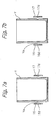
- the vessel Y is different from the conventional vessels which are formed with a smooth outer circumference. Namely, the vessel Y has, as shown in FIG. 7 a, on its outer circumference, a groove Ya with a nearly semicircular section extending entirely in the circumferential direction, and corresponding to this configuration, thin strip projections 16d, 17d with a nearly semicircular section are respectively formed on the inside surface of the gripping members 16,17 for gripping the vessel Y.
- Profiles of groove Ya and the projections 16d,17d are not limited to the semicircular shape. For example, a trapezoidal section as shown in FIG. 7b may be employed. Further, a projection may be provided on the vessel Y while grooves may respectively be formed on the gripping members 16,17.
- the groove Ya according to the present embodiment is formed at a position lower than the center in the height direction of the vessel.
- Numeral 31 denotes a motor mounted on the main rotating shaft supporting part 6 of the frame 4 (see FIG. 2).
- An output shaft 32 of the motor 31 extends through the supporting part 6, and a driving gear 33 located between the supporting parts 5 and 6 is fixed to the front end thereof.
- This driving gear 33 meshes with a driven gear 34 fixed to the main rotating shaft 7.
- the motor 31 turns intermittently in the same direction to rotate the main rotating shaft 7 every 180 degrees in the clockwise direction as viewed in FIG. 1 and in the counterclockwise direction as viewed in FIG. 4.
- the supporting shafts 9, 10 are also rotated in one around the center of the main rotating shaft 7.
- a cam lever 35 is fixedly secured at one end thereof to the end part of the supporting shafts 9 (10) projecting upwardly from the main rotating shaft 7 (see FIG. 4).
- a cam roller 36 is mounted on the other end of the lever 35.
- a grooved cam 37 is fixed to the main rotating shaft supporting part 6.
- a groove 38 is formed on the cam 37 and the cam roller 36 is fitted in and rolls along the groove 38.
- the groove 38 is provided with a uniform part 38a where the inside and outside walls 39 and 40 of the groove 38 are concentric with each other, having its center at the center of the main rotating shaft 7.
- the width of the uniform part 38a of the groove 38 nearly corresponds to the diameter of the cam roller 36.
- the groove 38 is also provided with an enlarged part 38b with an increased width.
- the inside wall 39 has a concentric part 39a, and a displacement part 39b where the radius of curvature is decreased gradually and is increased gradually again as going in the counterclockwise direction from the left upper part to the lower part in FIG. 4.
- the outside wall 40 has a concentric part 40a, and a displacement part 40b where the radius of curvature is increased gradually and is decreased again at the upper part. Therefore, the supporting shafts 9, 10 are unable to rotate as long as the cam roller 36 is located in the uniform part 38a while rotating is possible in the enlarged part 38b.
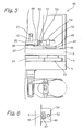
- FIG. 5 is a plan view showing details of the stopper mechanism 45 and FIG. 6 is its right side view.
- Numeral 46 denotes a rail of the stopper mechanism 45 that is secured to the main rotating shaft supporting part 6 of the frame 4.
- a slide member 47 is mounted on the rail 46 to be movable in the lateral direction as viewed in FIGS. 4 and 5.
- a slide plate 48 is fixed integrally on the slide member 47, a stopper roller 50 is mounted on the left side end part of the slide plate 48 as viewed in FIG.
- a contacting part 51 contacting a shock absorber 52 (which will be described later) is provided on the slide plate 48 to stand on the right side of the roller 50.
- the shock absorber 52 is mounted on the main rotating shaft supporting part 6 through a bracket 54.
- the contacting part 51 of the slide plate 48 is provided to contact with a contacting shaft 53 of the shock absorber 52.
- the position of this shock absorber 52 is adjustable in the axial direction of the contacting shaft 53.
- the first supporting shaft 9 When the main rotating shaft 7 starts to rotate from the state shown in FIG. 1, etc., the first supporting shaft 9 is unable to rotate around its axis during an early stage, since the cam roller 36 on the cam lever 35 attached to the shat 9 moves along and rolls in such a portion where the width of the groove 38 of the cam 37 is uniform, and the shaft 9 simply rotates or does a revolution around the axis of the main rotating shaft 7 integrally with the main rotating shaft 7.
- the cam roller 36 comes to the displacement part 40b of the outside wall 40 of the groove 38 and further to the displacement part 39b of the inside wall, the width of the groove 38 becomes greater than the diameter of the cam roller 36.
- the cam roller 36 moves in such a manner that the cam roller 36 rolls on the inside wall 39b, and the cam lever 35 and the supporting shaft 9 rotate around the axis of the supporting shaft 9 in the clockwise direction as viewed in FIG. 4.
- the cam lever 35 and the gripping members 16, 17 attached to the lever 35 rotate around the axis of the main shaft 7 in a slightly delayed state with regard to the main rotating shaft 7.
- the vessel Y is not in a completely inverted state. This is because considerations are given to the direction along which the contents in the vessel Y are discharged at the sudden stop of the vessel Y, which consideration is dealt with in the description of the prior art mentioned above.
- the direction of discharging can be set in the optimum state by regulating the final stop position of gripping members 16, 17, i.e., the reversal stop position, by regulating the position of the shock absorber 52 of the stopper mechanism 45 described previously.
- the main rotating shaft 7 again resumes rotating in the same direction at a predetermined timing, and the second supporting shaft 10 positioned at the reversal stop position in the figures starts returning movement to the gripping stop position described previously where the first supporting shaft 9 exists in the figures.
- the supporting shaft 10 rotates together with the main rotating shaft 7 in such a manner that the cam lever 35 presses the shock absorber 52 through the stopper roller 50, and the cam lever 35 is disengaged from the stopper roller 50.
- the supporting shaft 10 rotates by a predetermined angle in the direction opposite to the previous one, and the positional relationship between the supporting shaft 10 and the main rotating shaft 7 is restored to the original state.
- the roller 21 attached to the sliding shaft 12 described previously rests on the inclined part 25b of the gripping member opening/closing cam 25 also described previously, and then rides on the flat part 25a at a predetermined turning position to open the gripping members 16, 17, thereby discharging the vessel Y having being gripped till then.
- the vessel carrying-out apparatus 61 is equipped with an empty vessel collection conveyor 62, and a vessel collection guide 63 is mounted on the stand 3 by a bracket 64.
- the guide 63 extends between a receiving side end of the conveyor 62 and a cutout 56a formed through the guide cylinder 56.
- the vessel Y being griped by the gripping members 16, 17 can pass through the cutout 56a.
- the gripping members 16, 17 open, and the empty vessel Y discharged and received on the empty vessel collection guide 63 moves onto the conveyor 62 and is transferred to downstream process while being guided by guide bars 65.
- the main rotating shaft 7 continues rotating, and stops after rotated by 180 degrees, while the gripping members 16, 17 return to the gripping stop position in the opened state.
- the rotating speed of the motor 31 changes with two steps mode during one operation.
- relatively low-speed is employed in the stages before completion of discharging of the vessel, and then the speed is shifted to a higher speed after discharging the vessel, thereby ensuring reliable and thorough ejection of the contents accommodated in the vessel Y at the reversal stop position.
- two supporting shafts are provided and two sets of gripping members are used for one main rotating shaft.
- the gripping members can be mounted directly on the main rotating shaft.
- a servo motor may be used as a driving motor for appropriately regulating the rotational angle from the gripping stop position to the reversal stop position and the rotational angle in the returning process from the reversal stop position to the gripping stop position, so that the stopper mechanism used in the embodiment described above is unnecessary.
Landscapes
- Engineering & Computer Science (AREA)
- Mechanical Engineering (AREA)
- Specific Conveyance Elements (AREA)
- Basic Packing Technique (AREA)
- Auxiliary Devices For And Details Of Packaging Control (AREA)
- Supplying Of Containers To The Packaging Station (AREA)
- Filling Of Jars Or Cans And Processes For Cleaning And Sealing Jars (AREA)
Abstract
Description
- The present invention relates to a contents-filling vessel reversing apparatus for use in a bag packaging machine, namely an apparatus for reversing a vessel accommodating contents to be filled into a container such as, for example, a packaging bag. More specifically, the present invention relates to a contents-filling vessel reversing apparatus for reversing a vessel accommodating contents to be filled into a container from a upright state to an inverted state, thereby dropping downward and filling the contents into a packaging container disposed underneath, when foods or the like are packaged in the packaging container. The present invention also relates to a contents-filling vessel for accommodating contents to be filled into a packaging container which vessel are suitable for use with the contents-filling vessel reversing apparatus.
- In automatic packaging of foods and the like, filling of contents to be filled is usually carried out in such manner that vessels each accommodating a predetermined amount of contents such as foods or the like to be filled into a packaging container are supplied successively, this vessel is griped by such as, for example, a pair of gripping members which are capable of approaching to and separating away from each other, then the vessel is reversed from an upright state to a reversed state by rotating these gripping members in a vertical plane around a predetermined axis to drop the contents in the vessel into a packaging container disposed underneath. An example of the reversing apparatus of this type is described in, for example, Japanese Utility Model Publication No.H 7-20007.
- With a reversing apparatus described in this publication, a vessel is held by gripping members provided at one end of an rotating arm and the vessel is reversed from an upright state to an inversed state by rotating the arm by approximately 180 degrees, and the vessel still in a being accelerated state is released at this reversed position. The vessel is then hit and stopped by such as a stopper plate or the like to discharge the contents contained in the vessel downwardly. Therefore, a big impact noise is generated at hitting, thereby resulting in one of causes responsible for deteriorated working environments. Further, the vessel may be chipped in part when hitting on the stopper, which may poses a problem that fragments generated are mixed into the packaging container (vessels made of resin are used in many cases).
- Next, according to Japanese Patent Publication No. 2929476, a cushion member made of, for example, rubber or the like is provided at the stopper portion. Although the impact noise is reduced to a certain extent, this attempt is still not deemed satisfactory. Due to repeated hitting, the rubber as the cushion member as well as the vessel are worn and in some cases, fragments are mixed into the contents to be filled. Besides, in the case viscosity of the contents is relatively high, discharging of the contents from the vessel may become imperfect due to the cushioning action of the cushion member.
- According to Japanese Utility Model Laid-open No. 2539246, when an arm stops at the position rotated by 180 degrees, contents in the vessel are discharged downwardly due to inertia force. The vessel is then released to drop downward, and stopped by hitting a stopper plate. Although, compared with the above-mentioned two examples, the problems associated with the impact is relaxed, this proposal does not present a perfect solution. If the reversing speed is increased in an attempt to improve the processing capability of the apparatus and to accomplish perfect discharge of the contents from the vessel, the contents discharged from the vessel do not drop directly downward when the arm is stopped, but rather tend to be discharged in the direction along with the arm rotating trajectory. In the result, adhesion of the contents to the side wall of the guide may take place, thereby causing another problem that the contents are not filled surely into the packaging container.
- For the vessel used in the conventional contents-filling vessel reversing apparatus including the above-mentioned examples, the vessels usually have a smooth outer circumference, upper and lower end faces free from projections and depressions. In the meantime, engaging surfaces of a pair of gripping members for gripping the vessel is also formed smooth. Therefore, it is necessary to grip the vessel with a considerably strong force in order to prevent the vessel from slipping off from the gripping members when the vessel is reversed. In some cases, a small portion of the contents may adhere onto the outer circumference of the vessel. Especially when the contents contain oily substance, the strength of the gripping force should be set at a higher level. Accordingly, wear of the vessel becomes excessive and durability becomes poor. Besides, there is a possibility that foreign matters generated by wear are mixed into the contents.
- The present invention is made in light of the problems with the prior art as mentioned above. The object of the present invention is to present a contents-filling vessel reversing apparatus capable of discharging the contents from the vessel without hitting it against a stopper or the like, thereby preventing generation of noises to realize favorable working environments, and in addition, avoiding breakage of the vessel and preventing entry of fragments of the vessel into the contents to be filled.
- It is another object of the present invention to present a contents-filling vessel reversing apparatus that enables improvement of the processing capability and ensures filling of contents into a packaging container regardless of the type, properties and amount of the contents to be filled.
- Further it is another object of the present invention to present a contents-filling vessel reversing apparatus that does not need so strong gripping force as required in the conventional apparatus and enables improvements of wear and durability of contents-filling vessels used.
- Still another object of the present invention is to present a contents-filling vessel for accommodating contents to be filled into a packaging container which can be used favorably with the above-mentioned contents-filling vessel reversing apparatus.
- In order to solve the problems as discussed above and to accomplish the objects mentioned above, the present invention presents:
- a contents-filling vessel reversing apparatus for reversing a vessel accommodating contents to be filled from a upright state to a nearly inverted state, thereby dropping downward and filling the contents into a packaging container disposed underneath, said apparatus comprising:
- a reversing device including a rotating device equipped with a main rotating member rotatable around an axis thereof for rotating intermittently the main rotating member in one direction and for stopping the main rotating member at a first and a second positions, and a pair of gripping members attached to the rotating device and being capable of approaching to and separating away from each other to grip and to release said vessel, said gripping members being designed to stop at a gripping stop position where said gripping members can grip a vessel supplied in said upright state when said main rotating member stops at the first stop position, and to stop at a reversal stop position where said vessel is held in said nearly inverted state when said main rotating member stops at the second position;
- a reversal stop position regulating device for regulating said reversal stop position of said gripping members;
- an empty vessel carrying-out device provided at an empty vessel discharging position on the way along which said gripping members return from said reversal stop position to said gripping stop position, said empty vessel carrying-out device receiving an empty vessel from which the contents to be filled have been ejected and transferring it to downstream process; and
- a gripping member opening/closing apparatus for making said gripping members close to grip a vessel at said gripping stop position and for making said gripping members open at said empty vessel discharging position, thereby discharging the empty vessel towards the empty vessel carrying-out device.
- In the apparatus with the compositions mentioned above, the gripping members grip a vessel and rotate, and when the gripping members stop at the reversal stop position, the vessel is in a reversed state and stopped, thereby discharging the contents in the vessel due to the inertia force. The empty vessel is still griped by the gripping members even after it is reversed and the contents is discharged, and is released towards the vessel carrying-out device on the way returning to the gripping stop position. Therefore, there is no direct collision of a vessel with a stopper plate as observed in the prior art and problems of chipping of vessels, entry of foreign matters into a packaging container and deterioration of working environments do not occur.
- Further, the reversal stop position can be regulated to any desired position by the reversal stop position regulating device and, therefore, it is possible to regulate the reversal stop position according to properties and amount of the contents to be filled, processing rate or the like to ensure accurate dropping of the contents into a packaging container disposed directly underneath.
- According to one embodiment, the main rotating member comprises a main rotating shaft rotating intermittently in one direction every 180 degrees, and the rotating device further comprises a supporting shaft supported by the main rotating shaft in parallel to the main rotating shaft in an axial direction and designed to be reciprocally rotatable around an axis thereof between an initial position and a rotated position. The contents-filling vessel reversing apparatus further comprises a supporting shaft rotating device for rotating the supporting shaft. The reversing stop position regulating device regulates the rotated position of the supporting shaft, and the pair of gripping members are mounted on one end of the supporting shaft.
- With these compositions mentioned above, the supporting shaft rotating device is designed to change the relative position of the supporting shaft to the main rotating shaft in the direction of rotation by turning the supporting shaft. Therefore, even when two sets of gripping members are provided and these are rotated intermittently every 180 degrees by the reversing device, it is possible to change the reversal stop position while the gripping stop position is fixed.
- As noted, the supporting shaft is rotated during the reversal operation. By setting appropriately the way of rotating of the supporting shaft, for example by not tilting the vessel greatly at the earlier stage of reversal and tilting the vessel rapidly and greatly at the last end stage of reversal, depending on type, properties, and amount of contents to be filled, it is possible to prevent the contents from flying out from the vessel at an stage earlier than desired.
- According to another embodiment of the present invention, the supporting shaft is formed to be hollow, and the gripping member opening/closing device comprises a sliding shaft inserted into the hollow section of the supporting shaft and movable in the axial direction. The sliding shaft is connected at one end to the gripping members, and the gripping members are opened and closed interlockingly with the axial direction movement of the sliding shaft.
- According to the composition mentioned above where a sliding shaft is disposed within a supporting shaft, peripheral arrangement of the reversal mechanism of the apparatus can be made compact, and ease of cleaning is improved.
- According to another embodiment, the supporting shaft rotating device is equipped with a grooved cam securely positioned with an axis thereof coinciding with the axis of said main rotating shaft, a lever fixed to the other end of said supporting shaft and a cam roller mounted on the lever so as to roll in and move along a groove formed in the grooved cam. Further, in a predetermined range in the groove extending in the opposite directions from a position corresponding to the rotated position of the supporting shaft, at least a radius of curvature of an inner wall of said groove is made shorter than a radius of curvature of the inner wall in a rest range in the groove so that a width of the groove in said predetermined range is larger than a width of the groove in the rest range. Still further, the reversal stop regulating device is provided with a positioning stopper which abuts against the lever to position the lever at the reversal stop position, and a stopper position regulating device for regulating the position of the stopper.
- According to the compositions mentioned above, it is possible to change the reversal stop position only by adjusting the position of the stopper, and the gripping stop position is unchanged even when the reversal stop position is changed. Therefore, the adjustment can be done easily.
- According to yet another embodiment of the present invention, two supporting shafts are provided symmetrically with respect to the axis of the main rotating shaft, and each of the supporting shafts is provided with a pair of the gripping members. Therefore, it is possible to improve processing capability of the apparatus.
- According to yet another embodiment of the present invention, the gripping members grip the vessel on the outer circumference thereof. The vessel is provided with a thin strip projection or a groove formed on the outer circumference and extending over the entire circumference of the vessel, while each of the gripping members is provided with a groove or a thin strip projection formed on the gripping face opposing to the vessel to engage with the thin strip projection or the groove on the vessel. This configuration ensures gripping of the vessel, and the vessel would not disengage erroneously from the gripping members. Therefore, it is not necessary to grip the vessel with excessively strong force, thereby preventing breakage or the like of the vessel. Further, projections or grooves having a nearly circular or trapezoidal section can make reliable and stable the engagement between the thin strip projection and the groove respectively provided on the vessel and gripping members. Besides, if a groove is formed on the vessel, breakage of the vessel due to collision of fellow thin strip projections of adjacent vessels as may be observed when the thin strip projection is formed on the vessel can be avoided.
- According to yet another embodiment of the present invention, the rotational speed of the main rotating member changes with at least two steps mode. A low speed may be employed during a first movement stage when the gripping members move from the reversal stop position to the vessel discharging position, and a speed higher than that of the first movement stage may be employed during a second movement stage when the gripping member move later to the gripping stop position. This make it possible to perform reliable delivery of an empty vessel to the empty vessel carrying-out device as well as reliable ejection of the contents from the vessel.
- In addition, the present invention presents a contents-filling vessel for accommodating contents to be filled for preferable use with the above-mentioned contents-filling vessel reversing apparatus. The vessel is provided with a groove or a thin strip projection formed on the outer circumference thereof and extending over the entire circumference thereof.
- In one embodiment, the sectional profile of the groove or thin strip projection is nearly semicircular or trapezoidal in section.
- As discussed above, according to the present invention, breakage of a vessel during operation can be prevented and entry of foreign matters into packaging containers can be prevented. Further, noise generation can be reduced, which contributes to improvement of working environments. Furthermore, it is possible to prevent the contents in the vessel from erroneously flying out from the vessel at an undesired stage during operation, and the contents can be dropped surely into a packaging container located directly below the reversal position. Adjustments for this purpose can easily be done.
-
- FIG. 1 is a partly sectioned front view of a contents-filling vessel reversing apparatus according to a preferred embodiment of the present invention,
- FIG. 2 is a partly sectioned plan view thereof,
- FIG. 3 is a partly sectioned right side view thereof,
- FIG. 4 is a rear view showing the principal portion of the apparatus,
- FIG. 5 is a plan view showing a stopper mechanism used in the apparatus,
- FIG. 6 is a right side view of the stopper mechanism,
- FIG 7a is a sectional view of a contents-filling vessel used with the apparatus, and
- FIG 7b is a sectional view showing another embodiment of a contents-filling vessel.
- Referring now to the drawings, a preferred embodiment of the present invention will be explained hereinafter. FIG. 1 is a partly sectioned front view showing a contents-filling vessel reversing apparatus 1 (referred to simply as "apparatus" hereinafter) for reversing a contents-filling vessel (referred to simply as "vessel" hereinafter) accommodating contents to be filled according to a preferred embodiment of the present invention. FIG. 2 is a sectional plan view, FIG. 3 is a partly sectioned side view, and FIG. 4 is a rear view showing the principal part of the apparatus. According to the present embodiment, two sets of mechanisms for gripping and reversing a vessel Y are provided as will be described hereinafter.
- The
apparatus 1 has amachinery mount 2. Astand 3 is erected on themachinery mount 2, and aframe 4 in a nearly box-shaped configuration is secured on thestand 3. Twovertical wall portions frame 4 as viewed in FIG. 2. The walls form supportingparts rotating shaft 7. The mainrotating shaft 7 is supported throughbearings shaft 7 at right and left symmetrical positions with respect to the center of the mainrotating shaft 7. Supportingshafts bearings 11 disposed at the opposite ends of the mainrotating shaft 7, respectively. (For convenience of explanation, one shown at the left in FIG. 2 is referred to as a first supportingshaft 9 while one shown at the right is referred to as a second supportingshaft 10. When no discrimination is needed or they are identified unmistakably, however, they are simply referred to as supportingshaft 9 or supportingshaft 10.) The supportingshafts shaft 9 and the associated members only. - In the figures, the supporting
shaft 9 and the associated members are at a gripping stop position capable of gripping a vessel Y; while the supportingshaft 10 and the associated members are at a reversal stop position, i.e. vessel Y is in a nearly inverted state. The vessel Y according to the present embodiment is a cylindrical vessel having a bottom and is supplied successively by asupply conveyor 71 to the position shown (see FIG.1). - A through hole is formed through the supporting
shaft 9, and a slidingshaft 12 is inserted through this through hole. Although the slidingshaft 12 is movable in the axial direction, no turning is possible. One end of the sliding shaft 12 (lower side in FIG.2) is projected from the supportingshaft 9, and acylindrical part 14 formed at the base part of a grippingmember supporting block 13 is fitted on this projecting portion. Theblock 13 is fixed to anflange part 9a formed at one end of the supportingshaft 9. The supportingblock 13 is equipped with afork part 15, and a left grippingmember 16 and a right grippingmember 17 which rotate together with supportingpins fork part 15. - A
link linkage member 18 is securely mounted on the end of the slidingshaft 12 projecting from thecylindrical part 14 of the grippingmember supporting block 13. On the opposite side surface of thecylindrical part 14, one end of alink 18a is rotatably connected to the link linkage member 18 (see the second supportingshaft 10 and the associated members in FIG. 2.), and one end of connectingarm part 17b of the right grippingmember 17 is rotatably connected to the other end of thelink 18a. Anengagement pin 19 is fixed to stand on anengagement arm part 17c of the right grippingmember 17 extending in a direction nearly orthogonal to the connectingarm part 17b, and anelongated hole 16c formed through alinking arm part 16b of the left grippingmember 16 is fitted to thispin 19 so that a motion is transmitted between both grippingmembers - A
spring receiving part 12a with an increased diameter is formed on the slidingshaft 12 at a portion inside of thecylindrical part 14 of the grippingmember supporting block 13, and acompression spring 20 is disposed between this receivingpart 12a and an inside end face of thecylindrical part 14 of the supportingblock 13. Therefore, this spring acts to urge the right and left grippingmembers - A
roller 21 is attached to the opposite end of the slidingshaft 12 through anattachment shaft 22. With regard to thisroller 21, a gripping member opening/closing cam 25 is disposed and securely mounted on the front end of arod 24a of anair cylinder 24 that is mounted on theframe 4 through anattachment bracket 23. The opening/closing cam 25 is in the shape of a nearly semicircle ring (see FIG. 4), and a face thereof facing theroller 21 comprisesflat part 25a andinclined part 25b. Theinclined part 25b inclines in a direction where it is gradually separated away more from theroller 21 as going towards the end thereof (see FIGS. 2 and 4, in this condition illustrated, theroller 21 associated with the first supportingshaft 9 is placed on theflat part 25a and theroller 21 associated with the second supportingshaft 10 is disengaged from the cam 25). - When the main
rotating shaft 7 is in the stationary state and the first supportingshaft 9 and the associated slidingshaft 12 are in the position shown in FIG. 2, theair cylinder 24 is actuated to retract itsrod 24a, thecam 25 is moved backwardly, and the grippingmembers roller 21 associated with the first supportingshaft 9 is disengaged from thecam 25, theair cylinder 24 is actuated in the reverse direction, thereby returning thecam 25 to its original position. As will be described later, after the mainrotating shaft 7 is stopped at the reversal stop position where the vessel Y is reversed (in the drawings, the second supportingshaft 10 is in this position), and when it resumes rotating in the same direction in order to return to the gripping stop position, theroller 21 is rested on theinclined part 25b of thecam 25 on the way of returning, and then on theflat part 25a, thereby opening again grippingmembers - Referring to FIG. 7, the vessel Y and the gripping
members thin strip projections members members projections member members projections members - Referring again to FIGS. 1 to 4, a mechanism for reversing the vessel Y will be described.
Numeral 31 denotes a motor mounted on the main rotatingshaft supporting part 6 of the frame 4 (see FIG. 2). Anoutput shaft 32 of themotor 31 extends through the supportingpart 6, and adriving gear 33 located between the supportingparts driving gear 33 meshes with a drivengear 34 fixed to the mainrotating shaft 7. According to the present embodiment, themotor 31 turns intermittently in the same direction to rotate the mainrotating shaft 7 every 180 degrees in the clockwise direction as viewed in FIG. 1 and in the counterclockwise direction as viewed in FIG. 4. In this case, the supportingshafts rotating shaft 7. - In FIG. 2, a
cam lever 35 is fixedly secured at one end thereof to the end part of the supporting shafts 9 (10) projecting upwardly from the main rotating shaft 7 (see FIG. 4). Acam roller 36 is mounted on the other end of thelever 35. Corresponding to thesecam rollers 36, agrooved cam 37 is fixed to the main rotatingshaft supporting part 6. Agroove 38 is formed on thecam 37 and thecam roller 36 is fitted in and rolls along thegroove 38. Thegroove 38 is provided with auniform part 38a where the inside andoutside walls groove 38 are concentric with each other, having its center at the center of the mainrotating shaft 7. The width of theuniform part 38a of thegroove 38 nearly corresponds to the diameter of thecam roller 36. Thegroove 38 is also provided with anenlarged part 38b with an increased width. Namely, theinside wall 39 has aconcentric part 39a, and adisplacement part 39b where the radius of curvature is decreased gradually and is increased gradually again as going in the counterclockwise direction from the left upper part to the lower part in FIG. 4. Further, theoutside wall 40 has aconcentric part 40a, and adisplacement part 40b where the radius of curvature is increased gradually and is decreased again at the upper part. Therefore, the supportingshafts cam roller 36 is located in theuniform part 38a while rotating is possible in theenlarged part 38b. - In FIG. 4, corresponding to the end part of the
cam lever 35 associated with the second supportingshaft 10 on which end part thecam roller 36 is mounted, there is astopper mechanism 45 for regulating the stop position or the reversal position of the grippingmembers cam lever 35 and thus the position of the second supportingshaft 10. - In addition to FIG. 4, referring to FIGS. 5 and 6, FIG. 5 is a plan view showing details of the
stopper mechanism 45 and FIG. 6 is its right side view.Numeral 46 denotes a rail of thestopper mechanism 45 that is secured to the main rotatingshaft supporting part 6 of theframe 4. In FIGS. 4 and 5, aslide member 47 is mounted on therail 46 to be movable in the lateral direction as viewed in FIGS. 4 and 5. Aslide plate 48 is fixed integrally on theslide member 47, astopper roller 50 is mounted on the left side end part of theslide plate 48 as viewed in FIG. 5 by a supportingshaft 49, and a contactingpart 51 contacting a shock absorber 52 (which will be described later) is provided on theslide plate 48 to stand on the right side of theroller 50. Responding to the contactingpart 51, theshock absorber 52 is mounted on the main rotatingshaft supporting part 6 through abracket 54. The contactingpart 51 of theslide plate 48 is provided to contact with a contactingshaft 53 of theshock absorber 52. The position of thisshock absorber 52 is adjustable in the axial direction of the contactingshaft 53. - When the main
rotating shaft 7 starts to rotate from the state shown in FIG. 1, etc., the first supportingshaft 9 is unable to rotate around its axis during an early stage, since thecam roller 36 on thecam lever 35 attached to theshat 9 moves along and rolls in such a portion where the width of thegroove 38 of thecam 37 is uniform, and theshaft 9 simply rotates or does a revolution around the axis of the mainrotating shaft 7 integrally with the mainrotating shaft 7. When thecam roller 36 comes to thedisplacement part 40b of theoutside wall 40 of thegroove 38 and further to thedisplacement part 39b of the inside wall, the width of thegroove 38 becomes greater than the diameter of thecam roller 36. In this occasion, due to a load exerted to the supportingshaft 9, thecam roller 36 moves in such a manner that thecam roller 36 rolls on theinside wall 39b, and thecam lever 35 and the supportingshaft 9 rotate around the axis of the supportingshaft 9 in the clockwise direction as viewed in FIG. 4. In other words, thecam lever 35 and the grippingmembers lever 35 rotate around the axis of themain shaft 7 in a slightly delayed state with regard to the mainrotating shaft 7. - When the main
rotating shaft 7 is turned 180 degrees and is stopped, thecam lever 35 and the supportingshaft 9 now rotate counterclockwise around the axis of the supportingshaft 9, since the grippingmembers cam lever 35 on which thecam roller 36 is mounted collides with thestopper roller 50 described previously, and thecam lever 35, and thus the supportingshaft 9 also stop while the impact is being absorbed by theshock absorber 52. In FIGS. 1 to 4, the second supportingshaft 10 and the associated members are corresponding to this state. On this occasion, the vessel Y stops suddenly in a nearly reversed state as shown in FIG. 1, thereby discharging the contents accommodated in it into aguide cylinder 56 located underneath. As illustrated, the vessel Y is not in a completely inverted state. This is because considerations are given to the direction along which the contents in the vessel Y are discharged at the sudden stop of the vessel Y, which consideration is dealt with in the description of the prior art mentioned above. The direction of discharging can be set in the optimum state by regulating the final stop position of grippingmembers shock absorber 52 of thestopper mechanism 45 described previously. - Next, the main
rotating shaft 7 again resumes rotating in the same direction at a predetermined timing, and the second supportingshaft 10 positioned at the reversal stop position in the figures starts returning movement to the gripping stop position described previously where the first supportingshaft 9 exists in the figures. As the mainrotating shaft 7 rotates, the supportingshaft 10 rotates together with the mainrotating shaft 7 in such a manner that thecam lever 35 presses theshock absorber 52 through thestopper roller 50, and thecam lever 35 is disengaged from thestopper roller 50. When thecam roller 36 rolls on and moves along such a portion where the radius of curvature of thedisplacement part 39b of theinside wall 39 of thegroove 38 becomes greater gradually, the supportingshaft 10 rotates by a predetermined angle in the direction opposite to the previous one, and the positional relationship between the supportingshaft 10 and the mainrotating shaft 7 is restored to the original state. - Meanwhile, when the main
rotating shaft 7 rotates in this returning process, theroller 21 attached to the slidingshaft 12 described previously rests on theinclined part 25b of the gripping member opening/closing cam 25 also described previously, and then rides on theflat part 25a at a predetermined turning position to open thegripping members out apparatus 61 is disposed for receiving emptied vessels and transferring them to downstream process (see FIGS. 1, 3). The operations of discharging the vessel Y are carried out while the mainrotating shaft 7 continues rotating. - The vessel carrying-
out apparatus 61 is equipped with an emptyvessel collection conveyor 62, and avessel collection guide 63 is mounted on thestand 3 by abracket 64. Theguide 63 extends between a receiving side end of theconveyor 62 and acutout 56a formed through theguide cylinder 56. The vessel Y being griped by the grippingmembers cutout 56a. The grippingmembers vessel collection guide 63 moves onto theconveyor 62 and is transferred to downstream process while being guided by guide bars 65. The mainrotating shaft 7 continues rotating, and stops after rotated by 180 degrees, while the grippingmembers - According to the present embodiment described above, it is designed that the rotating speed of the
motor 31 changes with two steps mode during one operation. In other words, since discharging an empty vessel Y at too high speed may cause problems, relatively low-speed is employed in the stages before completion of discharging of the vessel, and then the speed is shifted to a higher speed after discharging the vessel, thereby ensuring reliable and thorough ejection of the contents accommodated in the vessel Y at the reversal stop position. - According to the embodiment described above, two supporting shafts are provided and two sets of gripping members are used for one main rotating shaft. However, when only one set of gripping members is used, the gripping members can be mounted directly on the main rotating shaft. On this occasion, a servo motor may be used as a driving motor for appropriately regulating the rotational angle from the gripping stop position to the reversal stop position and the rotational angle in the returning process from the reversal stop position to the gripping stop position, so that the stopper mechanism used in the embodiment described above is unnecessary.
Claims (12)
- Contents-filling vessel reversing apparatus for reversing a contents-filling vessel accommodating contents to be filled from a upright state to a nearly inverted state, thereby dropping downward and filling the contents into a packaging container disposed underneath, characterized by :a reversing device including a rotating device equipped with a main rotating member rotatable around an axis thereof , said rotating device rotating intermittently the main rotating member in one direction and stopping the main rotating member at a first and a second positions, and a pair of gripping members attached to the rotating device and being capable of approaching to and separating away from each other to grip and to release said vessel, said gripping members being designed to stop at a gripping stop position where said gripping members can grip a vessel supplied in said upright state when said main rotating member stops at the first stop position, and to stop at a reversal stop position where said vessel is held in said nearly inverted state when said main rotating member stops at the second position;a reversal stop position regulating device for regulating said reversal stop position of said gripping members;an empty vessel carrying-out device provided at an empty vessel discharging position on the way along which said gripping members return from said reversal stop position to said gripping stop position, said empty vessel carrying-out device receiving an empty vessel from which the contents to be filled have been ejected and transferring it to downstream process; anda gripping member opening/closing apparatus for making said gripping members close to grip a vessel at said gripping stop position and for making said gripping members open at said empty vessel discharging position, thereby discharging the empty vessel towards said empty vessel carrying-out device.
- A contents-filling vessel reversing apparatus according to Claim 1, characterized in :that said main rotating member comprises a main rotating shaft rotating intermittently in one direction every 180 degrees,that said rotating device further comprises a supporting shaft supported by said main rotating shaft in parallel to said main rotating shaft in an axial direction, and designed to be reciprocally rotatable around an axis thereof between an initial position and a rotated position,that said contents-filling vessel reversing apparatus further comprises a supporting shaft rotating device for rotating said supporting shaft, andthat said reversing stop position regulating device regulates said rotated position of said supporting shaft, and said pair of gripping members are mounted on one end of said supporting shaft.
- A contents-filling vessel reversing apparatus according to Claim 2, characterized in :that said supporting shaft is formed to be hollow to have a through hole,that said gripping member opening/closing device comprises a sliding shaft inserted through said through hole of said supporting shaft and being movable in an axial direction thereof, said sliding shaft being connected at one end thereof to said gripping members, andthat said gripping members are opened and closed interlockingly with the axial direction movement of said sliding shaft.
- A contents-filling vessel reversing apparatus according to Claim 2 or 3, characterized in :that said supporting shaft rotating device is equipped with a grooved cam securely positioned with an axis thereof coinciding with the axis of said main rotating shaft, a lever fixed to the other end of said supporting shaft and a cam roller mounted on the lever so as to roll in and move along a groove formed in said grooved cam,that, in a predetermined range in said groove extending in the opposite directions from a position corresponding to said rotated position, at least a radius of curvature of an inner wall of said groove is made shorter than a radius of curvature of the the inner wall in a rest range in the groove so that a width of the groove in said predetermined range is larger than a width of the groove in the rest range, andthat said reversal stop regulating device is provided with a positioning stopper which abuts against said lever to position the lever at said reversal stop position, and a stopper position regulating device for regulating the position of the stopper.
- A contents-filling vessel reversing apparatus according to any one of Claims 2 to 4, characterized in :that two said supporting shafts are provided symmetrically with respect to the axis of said main rotating shaft, and each of said supporting shafts is provided with said pair of gripping members.
- A contents-filling vessel reversing apparatus according to any one of Claims 1 to 5, characterized in :that said gripping members grip said vessel on a outer circumference thereof,that a thin strip projection or a groove is formed on the outer circumference of the vessel to extend over the entire circumference of said vessel, and a groove or a thin strip projection which engages with the thin strip projection or the groove on said vessel is formed on a surface of each of said gripping members opposing to said vessel.
- A contents-filling vessel reversing apparatus according to Claim 6, characterized in :that said thin strip projection are nearly semicircular or trapezoidal in section.
- A contents-filling vessel reversing apparatus according to Claim 6 or 7, characterized in :that said groove is formed on said vessel and said thin strip projection is formed on said gripping members.
- A content-filling vessel reversing apparatus according to any one of Claims 1 to 7, characterized in :that the rotational speed of said main rotating member changes with at least two steps, andthat a low-speed is employed in a first movement duration when said gripping members move from said reversal stop position to said vessel discharging position, and a speed higher than that of the first movement duration is employed in a second movement duration when said gripping members move to said gripping stop position thereafter.
- A vessel for use with a contents-filling vessel reversing apparatus for reversing a vessel accommodating contents to be filled from a upright state to a nearly inverted state, thereby dropping the contents in the vessel downward and filling the contents in a packaging container disposed underneath, characterized in that said vessel is provided with a groove or a thin strip projection formed on a outer circumference thereof to extend over the entire circumference of the vessel.
- A vessel according to Claim 10, characterized in that said groove or thin strip projection is nearly semicircular or trapezoidal in section.
- A vessel according to Claim 10 or 11, characterized in that said groove extending over the entire circumference is formed on the outer circumference of said vessel.
Applications Claiming Priority (1)
| Application Number | Priority Date | Filing Date | Title |
|---|---|---|---|
| JP2004208360A JP4473060B2 (en) | 2004-07-15 | 2004-07-15 | Filling container reversing device |
Publications (3)
| Publication Number | Publication Date |
|---|---|
| EP1616792A2 true EP1616792A2 (en) | 2006-01-18 |
| EP1616792A3 EP1616792A3 (en) | 2006-04-12 |
| EP1616792B1 EP1616792B1 (en) | 2008-03-26 |
Family
ID=35064810
Family Applications (1)
| Application Number | Title | Priority Date | Filing Date |
|---|---|---|---|
| EP05015011A Not-in-force EP1616792B1 (en) | 2004-07-15 | 2005-07-11 | A contents-filling vessel reversing apparatus and use of a vessel with the apparatus |
Country Status (6)
| Country | Link |
|---|---|
| US (1) | US20060010834A1 (en) |
| EP (1) | EP1616792B1 (en) |
| JP (1) | JP4473060B2 (en) |
| AT (1) | ATE390351T1 (en) |
| DE (1) | DE602005005563T2 (en) |
| ES (1) | ES2302101T3 (en) |
Cited By (1)
| Publication number | Priority date | Publication date | Assignee | Title |
|---|---|---|---|---|
| CN105292635A (en) * | 2015-10-21 | 2016-02-03 | 武汉鹏翼达科技有限公司 | Rotary bag unloading device |
Families Citing this family (4)
| Publication number | Priority date | Publication date | Assignee | Title |
|---|---|---|---|---|
| JP2006027656A (en) * | 2004-07-15 | 2006-02-02 | Toyo Jidoki Co Ltd | Apparatus for turning over container for filler material |
| JP5616192B2 (en) | 2010-10-18 | 2014-10-29 | 東洋自動機株式会社 | Filling container reversing device |
| JP7077374B2 (en) * | 2020-09-10 | 2022-05-30 | 株式会社東芝 | Automatic container processing equipment |
| CN112849607B (en) * | 2021-01-11 | 2022-12-13 | 安徽亚泰包装科技股份有限公司 | Reverse rotation device for packaging machine |
Citations (3)
| Publication number | Priority date | Publication date | Assignee | Title |
|---|---|---|---|---|
| JPH0720007Y2 (en) | 1990-05-31 | 1995-05-10 | 東洋自動機株式会社 | Automatic reversal discharge device for packing |
| JP2539246Y2 (en) | 1991-08-02 | 1997-06-25 | 東洋自動機株式会社 | Automatic reversal discharge device for filling |
| JP2929476B2 (en) | 1989-12-05 | 1999-08-03 | 光雄 輿水 | Automatic filling and filling machine |
Family Cites Families (11)
| Publication number | Priority date | Publication date | Assignee | Title |
|---|---|---|---|---|
| US3219170A (en) * | 1964-03-13 | 1965-11-23 | Fmc Corp | Inverting apparatus |
| FR2342936A1 (en) * | 1976-03-03 | 1977-09-30 | Gen Signal Corp | Handler and portable container for materials - facilitating storage, transport and processing e.g. mixing (SW 12.9.77) |
| US4087012A (en) * | 1977-04-18 | 1978-05-02 | Gerber Products Company | Assembly line container inverter |
| JPS59207327A (en) * | 1983-05-11 | 1984-11-24 | Ngk Insulators Ltd | Discharging device for matter contained in drum |
| US4546594A (en) * | 1983-12-27 | 1985-10-15 | Delkor Industries, Inc. | Machine and method for loading cartons with irregularly shaped individual articles |
| US5007227A (en) * | 1988-10-20 | 1991-04-16 | Mcclusky Machinery Sales & Service | Appartaus and method for packaging citrus fruit |
| US5025612A (en) * | 1989-11-29 | 1991-06-25 | Roberts Systems, Inc. | Inverted tray container loading apparatus |
| JP2844410B2 (en) * | 1993-06-30 | 1999-01-06 | 花王株式会社 | Method and apparatus for storing articles in container |
| JPH08282602A (en) * | 1995-04-10 | 1996-10-29 | Toyo Jidoki Co Ltd | Device for automatically reversing and discharging filler |
| JP2870446B2 (en) * | 1995-04-25 | 1999-03-17 | サンスター技研株式会社 | Cylindrical container loaded with inner bag |
| JP2006027656A (en) * | 2004-07-15 | 2006-02-02 | Toyo Jidoki Co Ltd | Apparatus for turning over container for filler material |
-
2004
- 2004-07-15 JP JP2004208360A patent/JP4473060B2/en not_active Expired - Fee Related
-
2005
- 2005-07-11 EP EP05015011A patent/EP1616792B1/en not_active Not-in-force
- 2005-07-11 ES ES05015011T patent/ES2302101T3/en active Active
- 2005-07-11 AT AT05015011T patent/ATE390351T1/en not_active IP Right Cessation
- 2005-07-11 DE DE602005005563T patent/DE602005005563T2/en not_active Expired - Fee Related
- 2005-07-14 US US11/181,437 patent/US20060010834A1/en not_active Abandoned
Patent Citations (3)
| Publication number | Priority date | Publication date | Assignee | Title |
|---|---|---|---|---|
| JP2929476B2 (en) | 1989-12-05 | 1999-08-03 | 光雄 輿水 | Automatic filling and filling machine |
| JPH0720007Y2 (en) | 1990-05-31 | 1995-05-10 | 東洋自動機株式会社 | Automatic reversal discharge device for packing |
| JP2539246Y2 (en) | 1991-08-02 | 1997-06-25 | 東洋自動機株式会社 | Automatic reversal discharge device for filling |
Cited By (1)
| Publication number | Priority date | Publication date | Assignee | Title |
|---|---|---|---|---|
| CN105292635A (en) * | 2015-10-21 | 2016-02-03 | 武汉鹏翼达科技有限公司 | Rotary bag unloading device |
Also Published As
| Publication number | Publication date |
|---|---|
| US20060010834A1 (en) | 2006-01-19 |
| JP2006027655A (en) | 2006-02-02 |
| EP1616792A3 (en) | 2006-04-12 |
| EP1616792B1 (en) | 2008-03-26 |
| ATE390351T1 (en) | 2008-04-15 |
| DE602005005563T2 (en) | 2008-06-26 |
| JP4473060B2 (en) | 2010-06-02 |
| ES2302101T3 (en) | 2008-07-01 |
| DE602005005563D1 (en) | 2008-05-08 |
Similar Documents
| Publication | Publication Date | Title |
|---|---|---|
| EP1616792B1 (en) | A contents-filling vessel reversing apparatus and use of a vessel with the apparatus | |
| US5519981A (en) | Twist-wrapping machine | |
| US20020144880A1 (en) | Bag conveying apparatus and a gripper endless chain used in a bag filling packaging machine | |
| JP5165563B2 (en) | Article transfer device, packaging device including the same, and weighing device | |
| EP1616791B1 (en) | A contents-filling vessel reversing apparatus | |
| CN109292160B (en) | Intelligent pet feed subpackaging device | |
| TWI389720B (en) | Bowling machine | |
| US4821865A (en) | Work delivering apparatus | |
| US4723722A (en) | Device for transferring bobbins to a spooling frame | |
| JP2539246Y2 (en) | Automatic reversal discharge device for filling | |
| EP1295841B1 (en) | Screw capper | |
| JP2006027655A5 (en) | ||
| TWI415656B (en) | Bowling machine | |
| TWI415657B (en) | Bowling game with recycling agencies | |
| EP0737618B1 (en) | Automatic machine for wrapping sweets or the like | |
| CN220579555U (en) | Embroidery machine feed supplement control mechanism | |
| KR0150027B1 (en) | Twist wrapping machine | |
| JP4537412B2 (en) | Apparatus and method for automatically closing envelopes | |
| JPH0712358Y2 (en) | Banknote stacking device | |
| RU2066613C1 (en) | Apparatus for charging hopper with rod-like parts | |
| SU190506A1 (en) | ||
| EP0653666B1 (en) | Slide projector | |
| SU1242428A1 (en) | Device for putting flap bags on horns of revolving packing machine | |
| SU1615083A1 (en) | Loading device | |
| JP2019123578A (en) | Feeding device |
Legal Events
| Date | Code | Title | Description |
|---|---|---|---|
| PUAI | Public reference made under article 153(3) epc to a published international application that has entered the european phase |
Free format text: ORIGINAL CODE: 0009012 |
|
| AK | Designated contracting states |
Kind code of ref document: A2 Designated state(s): AT BE BG CH CY CZ DE DK EE ES FI FR GB GR HU IE IS IT LI LT LU LV MC NL PL PT RO SE SI SK TR |
|
| AX | Request for extension of the european patent |
Extension state: AL BA HR MK YU |
|
| PUAL | Search report despatched |
Free format text: ORIGINAL CODE: 0009013 |
|
| AK | Designated contracting states |
Kind code of ref document: A3 Designated state(s): AT BE BG CH CY CZ DE DK EE ES FI FR GB GR HU IE IS IT LI LT LU LV MC NL PL PT RO SE SI SK TR |
|
| AX | Request for extension of the european patent |
Extension state: AL BA HR MK YU |
|
| 17P | Request for examination filed |
Effective date: 20060502 |
|
| 17Q | First examination report despatched |
Effective date: 20060703 |
|
| AKX | Designation fees paid |
Designated state(s): AT BE BG CH CY CZ DE DK EE ES FI FR GB GR HU IE IS IT LI LT LU LV MC NL PL PT RO SE SI SK TR |
|
| RTI1 | Title (correction) |
Free format text: A CONTENTS-FILLING VESSEL REVERSING APPARATUS AND USE OF A VESSEL WITH THE APPARATUS |
|
| GRAP | Despatch of communication of intention to grant a patent |
Free format text: ORIGINAL CODE: EPIDOSNIGR1 |
|
| GRAS | Grant fee paid |
Free format text: ORIGINAL CODE: EPIDOSNIGR3 |
|
| GRAA | (expected) grant |
Free format text: ORIGINAL CODE: 0009210 |
|
| AK | Designated contracting states |
Kind code of ref document: B1 Designated state(s): AT BE BG CH CY CZ DE DK EE ES FI FR GB GR HU IE IS IT LI LT LU LV MC NL PL PT RO SE SI SK TR |
|
| REG | Reference to a national code |
Ref country code: GB Ref legal event code: FG4D |
|
| REG | Reference to a national code |
Ref country code: IE Ref legal event code: FG4D Ref country code: CH Ref legal event code: EP |
|
| REF | Corresponds to: |
Ref document number: 602005005563 Country of ref document: DE Date of ref document: 20080508 Kind code of ref document: P |
|
| REG | Reference to a national code |
Ref country code: ES Ref legal event code: FG2A Ref document number: 2302101 Country of ref document: ES Kind code of ref document: T3 |
|
| PG25 | Lapsed in a contracting state [announced via postgrant information from national office to epo] |
Ref country code: FI Free format text: LAPSE BECAUSE OF FAILURE TO SUBMIT A TRANSLATION OF THE DESCRIPTION OR TO PAY THE FEE WITHIN THE PRESCRIBED TIME-LIMIT Effective date: 20080326 |
|
| PG25 | Lapsed in a contracting state [announced via postgrant information from national office to epo] |
Ref country code: AT Free format text: LAPSE BECAUSE OF FAILURE TO SUBMIT A TRANSLATION OF THE DESCRIPTION OR TO PAY THE FEE WITHIN THE PRESCRIBED TIME-LIMIT Effective date: 20080326 |
|
| NLV1 | Nl: lapsed or annulled due to failure to fulfill the requirements of art. 29p and 29m of the patents act | ||
| PG25 | Lapsed in a contracting state [announced via postgrant information from national office to epo] |
Ref country code: SI Free format text: LAPSE BECAUSE OF FAILURE TO SUBMIT A TRANSLATION OF THE DESCRIPTION OR TO PAY THE FEE WITHIN THE PRESCRIBED TIME-LIMIT Effective date: 20080326 Ref country code: PL Free format text: LAPSE BECAUSE OF FAILURE TO SUBMIT A TRANSLATION OF THE DESCRIPTION OR TO PAY THE FEE WITHIN THE PRESCRIBED TIME-LIMIT Effective date: 20080326 Ref country code: LV Free format text: LAPSE BECAUSE OF FAILURE TO SUBMIT A TRANSLATION OF THE DESCRIPTION OR TO PAY THE FEE WITHIN THE PRESCRIBED TIME-LIMIT Effective date: 20080326 Ref country code: BE Free format text: LAPSE BECAUSE OF FAILURE TO SUBMIT A TRANSLATION OF THE DESCRIPTION OR TO PAY THE FEE WITHIN THE PRESCRIBED TIME-LIMIT Effective date: 20080326 |
|
| PG25 | Lapsed in a contracting state [announced via postgrant information from national office to epo] |
Ref country code: SK Free format text: LAPSE BECAUSE OF FAILURE TO SUBMIT A TRANSLATION OF THE DESCRIPTION OR TO PAY THE FEE WITHIN THE PRESCRIBED TIME-LIMIT Effective date: 20080326 Ref country code: CZ Free format text: LAPSE BECAUSE OF FAILURE TO SUBMIT A TRANSLATION OF THE DESCRIPTION OR TO PAY THE FEE WITHIN THE PRESCRIBED TIME-LIMIT Effective date: 20080326 Ref country code: PT Free format text: LAPSE BECAUSE OF FAILURE TO SUBMIT A TRANSLATION OF THE DESCRIPTION OR TO PAY THE FEE WITHIN THE PRESCRIBED TIME-LIMIT Effective date: 20080901 Ref country code: SE Free format text: LAPSE BECAUSE OF FAILURE TO SUBMIT A TRANSLATION OF THE DESCRIPTION OR TO PAY THE FEE WITHIN THE PRESCRIBED TIME-LIMIT Effective date: 20080626 |
|
| PG25 | Lapsed in a contracting state [announced via postgrant information from national office to epo] |
Ref country code: RO Free format text: LAPSE BECAUSE OF FAILURE TO SUBMIT A TRANSLATION OF THE DESCRIPTION OR TO PAY THE FEE WITHIN THE PRESCRIBED TIME-LIMIT Effective date: 20080326 Ref country code: NL Free format text: LAPSE BECAUSE OF FAILURE TO SUBMIT A TRANSLATION OF THE DESCRIPTION OR TO PAY THE FEE WITHIN THE PRESCRIBED TIME-LIMIT Effective date: 20080326 |
|
| PG25 | Lapsed in a contracting state [announced via postgrant information from national office to epo] |
Ref country code: IS Free format text: LAPSE BECAUSE OF FAILURE TO SUBMIT A TRANSLATION OF THE DESCRIPTION OR TO PAY THE FEE WITHIN THE PRESCRIBED TIME-LIMIT Effective date: 20080726 |
|
| EN | Fr: translation not filed | ||
| PG25 | Lapsed in a contracting state [announced via postgrant information from national office to epo] |
Ref country code: LT Free format text: LAPSE BECAUSE OF FAILURE TO SUBMIT A TRANSLATION OF THE DESCRIPTION OR TO PAY THE FEE WITHIN THE PRESCRIBED TIME-LIMIT Effective date: 20080326 Ref country code: DK Free format text: LAPSE BECAUSE OF FAILURE TO SUBMIT A TRANSLATION OF THE DESCRIPTION OR TO PAY THE FEE WITHIN THE PRESCRIBED TIME-LIMIT Effective date: 20080326 |
|
| PLBE | No opposition filed within time limit |
Free format text: ORIGINAL CODE: 0009261 |
|
| STAA | Information on the status of an ep patent application or granted ep patent |
Free format text: STATUS: NO OPPOSITION FILED WITHIN TIME LIMIT |
|
| 26N | No opposition filed |
Effective date: 20081230 |
|
| PG25 | Lapsed in a contracting state [announced via postgrant information from national office to epo] |
Ref country code: MC Free format text: LAPSE BECAUSE OF NON-PAYMENT OF DUE FEES Effective date: 20080731 |
|
| PG25 | Lapsed in a contracting state [announced via postgrant information from national office to epo] |
Ref country code: FR Free format text: LAPSE BECAUSE OF FAILURE TO SUBMIT A TRANSLATION OF THE DESCRIPTION OR TO PAY THE FEE WITHIN THE PRESCRIBED TIME-LIMIT Effective date: 20090116 Ref country code: EE Free format text: LAPSE BECAUSE OF FAILURE TO SUBMIT A TRANSLATION OF THE DESCRIPTION OR TO PAY THE FEE WITHIN THE PRESCRIBED TIME-LIMIT Effective date: 20080326 Ref country code: DE Free format text: LAPSE BECAUSE OF NON-PAYMENT OF DUE FEES Effective date: 20090203 Ref country code: BG Free format text: LAPSE BECAUSE OF FAILURE TO SUBMIT A TRANSLATION OF THE DESCRIPTION OR TO PAY THE FEE WITHIN THE PRESCRIBED TIME-LIMIT Effective date: 20080626 |
|
| PG25 | Lapsed in a contracting state [announced via postgrant information from national office to epo] |
Ref country code: IE Free format text: LAPSE BECAUSE OF NON-PAYMENT OF DUE FEES Effective date: 20080711 |
|
| PG25 | Lapsed in a contracting state [announced via postgrant information from national office to epo] |
Ref country code: IT Free format text: LAPSE BECAUSE OF FAILURE TO SUBMIT A TRANSLATION OF THE DESCRIPTION OR TO PAY THE FEE WITHIN THE PRESCRIBED TIME-LIMIT Effective date: 20080326 |
|
| REG | Reference to a national code |
Ref country code: ES Ref legal event code: FD2A Effective date: 20080712 |
|
| PG25 | Lapsed in a contracting state [announced via postgrant information from national office to epo] |
Ref country code: CY Free format text: LAPSE BECAUSE OF FAILURE TO SUBMIT A TRANSLATION OF THE DESCRIPTION OR TO PAY THE FEE WITHIN THE PRESCRIBED TIME-LIMIT Effective date: 20080326 |
|
| PG25 | Lapsed in a contracting state [announced via postgrant information from national office to epo] |
Ref country code: ES Free format text: LAPSE BECAUSE OF NON-PAYMENT OF DUE FEES Effective date: 20080712 |
|
| REG | Reference to a national code |
Ref country code: CH Ref legal event code: PL |
|
| GBPC | Gb: european patent ceased through non-payment of renewal fee |
Effective date: 20090711 |
|
| PG25 | Lapsed in a contracting state [announced via postgrant information from national office to epo] |
Ref country code: LI Free format text: LAPSE BECAUSE OF NON-PAYMENT OF DUE FEES Effective date: 20090731 Ref country code: CH Free format text: LAPSE BECAUSE OF NON-PAYMENT OF DUE FEES Effective date: 20090731 |
|
| PG25 | Lapsed in a contracting state [announced via postgrant information from national office to epo] |
Ref country code: GB Free format text: LAPSE BECAUSE OF NON-PAYMENT OF DUE FEES Effective date: 20090711 |
|
| PG25 | Lapsed in a contracting state [announced via postgrant information from national office to epo] |
Ref country code: HU Free format text: LAPSE BECAUSE OF FAILURE TO SUBMIT A TRANSLATION OF THE DESCRIPTION OR TO PAY THE FEE WITHIN THE PRESCRIBED TIME-LIMIT Effective date: 20080927 Ref country code: LU Free format text: LAPSE BECAUSE OF NON-PAYMENT OF DUE FEES Effective date: 20080711 |
|
| PG25 | Lapsed in a contracting state [announced via postgrant information from national office to epo] |
Ref country code: TR Free format text: LAPSE BECAUSE OF FAILURE TO SUBMIT A TRANSLATION OF THE DESCRIPTION OR TO PAY THE FEE WITHIN THE PRESCRIBED TIME-LIMIT Effective date: 20080326 |
|
| PG25 | Lapsed in a contracting state [announced via postgrant information from national office to epo] |
Ref country code: GR Free format text: LAPSE BECAUSE OF FAILURE TO SUBMIT A TRANSLATION OF THE DESCRIPTION OR TO PAY THE FEE WITHIN THE PRESCRIBED TIME-LIMIT Effective date: 20080627 |