EP1616482A2 - Versuchstierbehausung mit Euthanasierfunktion - Google Patents
Versuchstierbehausung mit Euthanasierfunktion Download PDFInfo
- Publication number
- EP1616482A2 EP1616482A2 EP05106487A EP05106487A EP1616482A2 EP 1616482 A2 EP1616482 A2 EP 1616482A2 EP 05106487 A EP05106487 A EP 05106487A EP 05106487 A EP05106487 A EP 05106487A EP 1616482 A2 EP1616482 A2 EP 1616482A2
- Authority
- EP
- European Patent Office
- Prior art keywords
- air
- gas
- supply
- animals
- exhaust
- Prior art date
- Legal status (The legal status is an assumption and is not a legal conclusion. Google has not performed a legal analysis and makes no representation as to the accuracy of the status listed.)
- Withdrawn
Links
- 241001465754 Metazoa Species 0.000 title claims abstract description 131
- 238000010171 animal model Methods 0.000 title claims description 6
- 238000009423 ventilation Methods 0.000 claims abstract description 62
- 230000029058 respiratory gaseous exchange Effects 0.000 claims abstract description 30
- 238000013022 venting Methods 0.000 claims abstract description 11
- 239000007789 gas Substances 0.000 claims description 179
- 238000000034 method Methods 0.000 claims description 30
- QVGXLLKOCUKJST-UHFFFAOYSA-N atomic oxygen Chemical compound [O] QVGXLLKOCUKJST-UHFFFAOYSA-N 0.000 claims description 17
- 239000001301 oxygen Substances 0.000 claims description 17
- 229910052760 oxygen Inorganic materials 0.000 claims description 17
- 230000008878 coupling Effects 0.000 claims description 9
- 238000010168 coupling process Methods 0.000 claims description 9
- 238000005859 coupling reaction Methods 0.000 claims description 9
- 230000000694 effects Effects 0.000 claims description 8
- 239000000463 material Substances 0.000 claims description 4
- 238000004891 communication Methods 0.000 claims description 3
- 230000003213 activating effect Effects 0.000 claims description 2
- 238000011010 flushing procedure Methods 0.000 claims 1
- 238000006467 substitution reaction Methods 0.000 claims 1
- 206010015548 Euthanasia Diseases 0.000 abstract description 34
- 230000000977 initiatory effect Effects 0.000 abstract description 5
- 238000012986 modification Methods 0.000 abstract description 3
- 230000004048 modification Effects 0.000 abstract description 3
- CURLTUGMZLYLDI-UHFFFAOYSA-N Carbon dioxide Chemical compound O=C=O CURLTUGMZLYLDI-UHFFFAOYSA-N 0.000 description 118
- 239000003570 air Substances 0.000 description 116
- 229910002092 carbon dioxide Inorganic materials 0.000 description 110
- 239000001569 carbon dioxide Substances 0.000 description 110
- 241000699670 Mus sp. Species 0.000 description 12
- 230000008569 process Effects 0.000 description 10
- 238000002474 experimental method Methods 0.000 description 7
- 238000012545 processing Methods 0.000 description 6
- 206010003497 Asphyxia Diseases 0.000 description 5
- 235000011089 carbon dioxide Nutrition 0.000 description 5
- 231100000636 lethal dose Toxicity 0.000 description 5
- 231100000518 lethal Toxicity 0.000 description 4
- 230000001665 lethal effect Effects 0.000 description 4
- 238000010926 purge Methods 0.000 description 4
- 208000003443 Unconsciousness Diseases 0.000 description 3
- 238000012423 maintenance Methods 0.000 description 3
- 238000007789 sealing Methods 0.000 description 3
- IJGRMHOSHXDMSA-UHFFFAOYSA-N Atomic nitrogen Chemical compound N#N IJGRMHOSHXDMSA-UHFFFAOYSA-N 0.000 description 2
- GQPLMRYTRLFLPF-UHFFFAOYSA-N Nitrous Oxide Chemical compound [O-][N+]#N GQPLMRYTRLFLPF-UHFFFAOYSA-N 0.000 description 2
- 241000700159 Rattus Species 0.000 description 2
- 230000004913 activation Effects 0.000 description 2
- 238000004458 analytical method Methods 0.000 description 2
- 230000008901 benefit Effects 0.000 description 2
- 230000007423 decrease Effects 0.000 description 2
- 238000006073 displacement reaction Methods 0.000 description 2
- 230000006870 function Effects 0.000 description 2
- 230000001105 regulatory effect Effects 0.000 description 2
- 238000012163 sequencing technique Methods 0.000 description 2
- 230000007704 transition Effects 0.000 description 2
- 238000011144 upstream manufacturing Methods 0.000 description 2
- RYGMFSIKBFXOCR-UHFFFAOYSA-N Copper Chemical compound [Cu] RYGMFSIKBFXOCR-UHFFFAOYSA-N 0.000 description 1
- 241000282412 Homo Species 0.000 description 1
- 241000283973 Oryctolagus cuniculus Species 0.000 description 1
- 206010041349 Somnolence Diseases 0.000 description 1
- 230000002411 adverse Effects 0.000 description 1
- 239000012080 ambient air Substances 0.000 description 1
- 239000010868 animal carcass Substances 0.000 description 1
- 230000008859 change Effects 0.000 description 1
- 230000001276 controlling effect Effects 0.000 description 1
- 238000001816 cooling Methods 0.000 description 1
- 229910052802 copper Inorganic materials 0.000 description 1
- 239000010949 copper Substances 0.000 description 1
- 230000009849 deactivation Effects 0.000 description 1
- 238000010586 diagram Methods 0.000 description 1
- 238000001914 filtration Methods 0.000 description 1
- 238000007667 floating Methods 0.000 description 1
- 238000002695 general anesthesia Methods 0.000 description 1
- 239000003193 general anesthetic agent Substances 0.000 description 1
- 230000006872 improvement Effects 0.000 description 1
- 238000002347 injection Methods 0.000 description 1
- 239000007924 injection Substances 0.000 description 1
- 238000009434 installation Methods 0.000 description 1
- 239000000203 mixture Substances 0.000 description 1
- 239000002991 molded plastic Substances 0.000 description 1
- 238000012544 monitoring process Methods 0.000 description 1
- 229910052757 nitrogen Inorganic materials 0.000 description 1
- 239000001272 nitrous oxide Substances 0.000 description 1
- 239000002245 particle Substances 0.000 description 1
- 230000037361 pathway Effects 0.000 description 1
- 230000000737 periodic effect Effects 0.000 description 1
- 238000003825 pressing Methods 0.000 description 1
- 238000009877 rendering Methods 0.000 description 1
- 238000002791 soaking Methods 0.000 description 1
- 239000007787 solid Substances 0.000 description 1
- 239000000243 solution Substances 0.000 description 1
- 239000007858 starting material Substances 0.000 description 1
- 230000000472 traumatic effect Effects 0.000 description 1
- XLYOFNOQVPJJNP-UHFFFAOYSA-N water Substances O XLYOFNOQVPJJNP-UHFFFAOYSA-N 0.000 description 1
Images


Classifications
-
- A—HUMAN NECESSITIES
- A01—AGRICULTURE; FORESTRY; ANIMAL HUSBANDRY; HUNTING; TRAPPING; FISHING
- A01K—ANIMAL HUSBANDRY; AVICULTURE; APICULTURE; PISCICULTURE; FISHING; REARING OR BREEDING ANIMALS, NOT OTHERWISE PROVIDED FOR; NEW BREEDS OF ANIMALS
- A01K1/00—Housing animals; Equipment therefor
- A01K1/02—Pigsties; Dog-kennels; Rabbit-hutches or the like
- A01K1/03—Housing for domestic or laboratory animals
- A01K1/031—Cages for laboratory animals; Cages for measuring metabolism of animals
-
- A—HUMAN NECESSITIES
- A22—BUTCHERING; MEAT TREATMENT; PROCESSING POULTRY OR FISH
- A22B—SLAUGHTERING
- A22B3/00—Slaughtering or stunning
-
- A—HUMAN NECESSITIES
- A22—BUTCHERING; MEAT TREATMENT; PROCESSING POULTRY OR FISH
- A22B—SLAUGHTERING
- A22B3/00—Slaughtering or stunning
- A22B3/005—Slaughtering or stunning by means of gas
Definitions
- the invention relates to the field of laboratory animal handling, providing an animal housing cage rack system with a euthanizing capability.
- the animals in all or part of a cage rack of the type that normally houses the animals can be asphyxiated by automatic staged displacement of cage air with CO 2 gas. In this way the animals are euthanized with minimal associated stress and without danger to human operators.
- High density animal housing facilities are known, for example, from U.S. Patents 5,044,316; 4,690,100; 4,402,280; and 4,343,261, wherein small animals such as mice, rats, rabbits or the like are housed in molded plastic cage boxes that are supported on hollow shelves with integral air supply and air exhaust ducts.
- the cage boxes are supported on flanges under the shelves. Openings in the underside of the shelves allow the supply and exhaust ventilation air lines to be coupled through the open tops of the cage boxes, or in some embodiments couple through a filter cover or a valved lid that rests between the cage box and the underside of the associated shelf.
- a lid or sealing filter cover between the cage box and shelf can help to seal the ventilation paths, but there is typically some leakage of ventilation air. It is possible to maintain the air pressure in such a cage rack at a higher or lower pressure than ambient atmospheric pressure. The result is some flow of leakage air, either outwardly from the cages into the surrounding air, or inwardly from the surrounding air into the cages.
- the primary flow of air through the caging system originates at a preferably filtered supply, passes from the hollow ducted shelves through the cages and is extracted and exhausted or recirculated. Blowers upstream and downstream of the cage boxes can be employed. The pressure of the supply is balanced with the suction of the exhaust so as to maintain the cage internal pressure close to ambient pressure.
- High density caging systems as described are particularly apt for laboratory experimentation involving a large number of individual animals that are subjected to experimental procedures or exist as control animals for purposes of comparison. In some facilities, quite a large number of animals are housed to support plural ongoing experiments.
- euthanasia may be a prerequisite to physical analyses associated with assaying experimental results. Insofar as animals may have participated in an experiment even as controls, euthanasia and physical analysis may be required for comparison with other subjects. Animals that may have lived through a given experiment are often unsuitable as subjects in a later experiment due to potential influence from the former experiment. Continued maintenance of such animals cannot be justified. In these circumstances and other similar circumstances, it may be necessary to euthanize the animals.
- a common euthanasia technique is CO 2 gas overdose.
- the technique may be stressful to the animals. It is desirable that the animals not be traumatized.
- the CO2 gas technique also can be labor intensive, particularly where a large number of animals are to be euthanized.
- Dry ice is very cold and its use as a supply of CO 2 gas is considered likely to traumatize the animals. Use of dry ice for euthanasia is generally considered an unacceptable practice.
- Anderson uses a CO 2 gas supply from a gas cylinder, associated with a gas valve and timer that the operator adjusts and monitors. In Anderson, the pressurized gas is discharged into the cage box through a fitting in a cage box cover. It would appear that releasing gas pressure in this way would also substantially reduce the temperature of the gas, but at least there is no block of concentrated very cold CO 2 gas dry ice.
- the Anderson technique is more humane than some other common euthanizing techniques, such as guillotining the animals one by one. Nevertheless, there is stress for the animals and work for the technician. Anderson teaches enclosing the animals in a box and airtight lid for application of the timed asphyxiation process. Although the animals might be processed in their individual home cage boxes, there is stress in removing the cage boxes from their normal location, sealing the gas fitting lid to each individual cage box in turn and proceeding with the timed process. Processing one box at a time is time consuming and inefficient for the operator, who is inclined to combine unfamiliar animals into one cage box for processing. Combining unfamiliar animals in a cage is stressful for the animals. One might extend Anderson to combining a number of cage boxes in some sort of sealed vault for application of the process, which would also be stressful for the animals and inefficient for the operator.
- a technique is disclosed wherein a copper manifold pipe is attached to the air supply plenum at the end of a ventilating cage rack, and has nozzles of progressively different sizes arranged to emit CO 2 gas at different points along a flow path.
- a cage rack that is partly or completely loaded with animal cages first is disconnected from the ventilation air supply arrangements.
- the air supply plenum at the end of the rack is opened and the manifold is clamped into place inside the plenum, so as to direct the nozzles toward the animal cages.
- the manifold is then coupled to a CO 2 gas supply that delivers gas at 30 psi, for a sufficient time to asphyxiate the mice. Afterwards, the clamped-in manifold is detached and removed.
- the rack is reconnected to the ventilation air supply and operated to expel residual CO 2 gas.
- the AALAS Abstract solution has certain advantages in that the animals can be asphyxiated in their "home" rack, presumably without stress.
- this advantage is achieved with substantial inconvenience for the operators, who are to disassemble the air supply and air plenum structures for each cage rack to be processed, modify the cage rack by installing a CO 2 gas emission apparatus, operate the CO 2 gas supply with sufficient pressure, flow and timing controlled manually, and finally to remove these arrangements afterwards.
- a standard cage rack is coupled by its standard ventilation couplings to an automatically controlled gas supply apparatus operable to substitute euthanizing gas for ventilation air in a series of controlled operations.
- the device automatically obtains an initial anesthetizing concentration, proceeds to time a lethal soak concentration wherein the flow of air or gas is stopped, and finally vents the cage rack by resuming ventilation air flow, all automatically.
- a high density animal housing system with a ventilation system having an air source conduit and an air exhaust conduit that normally supply air for respiration of the animals.
- the system is coupled to a controller that activates and deactivates associated blowers and valves so as to substitute CO 2 gas for ventilation air.
- the system first anesthetizes and then euthanizes the animals via that same flow conduits that otherwise supply respiration air.
- the sequence progresses through insufflation of the cages with gas, substituting the gas for inlet air over a timed interval while an exhaust blower continues to run.
- the exhaust flow is discontinued.
- a final venting phase the gas is flushed to the exhaust.
- Operator inputs can select among sequences. Status sensing inputs prevent initiation or continuation of a cycle in the event of certain faults.
- the animal cages preferably are air impermeable boxes suspended from hollow shelves that define internal conduits for supply and exhaust of air, coupled to the supply and exhaust conduits.
- a gas preferably CO 2 is supplied while continuing to operate the exhaust system for a defined period of time. This insufflates the system, i.e., increases the concentration of CO 2 gas in the cages, first anesthetizing the animals and eventually displacing oxygen to a lethal concentration of gas.
- the CO 2 gas supply preferably is shut off, and the exhaust system is stopped for a further timed "soak" interval.
- the cessation of ventilation currents permits the CO 2 gas, which is heavier than air, to settle without turbulence in the cages, displacing any oxygen and further increasing the CO 2 gas concentration while removing oxygen, in the areas occupied by the animals.
- the inlet is recoupled to ventilation air system, the CO 2 gas supply remains shut off and the exhaust is operated to permit the cages to be vented. The cages and animals can be removed safely.
- the invention provides a device that substitutes CO 2 gas for the cage ventilation air in a cage rack, by coupling a low pressure CO 2 gas supply to the ventilation paths of a standard and unmodified cage rack.
- the user has the option to select from among a number of pre-programmed cycles or sequences of operation that are controllably executed by a programmed ventilation supply facility that is coupleable to the standard ventilation fittings of a standard cage rack. It is an easy matter, particularly with cage racks having caster wheel chassis, to remove and exchange a rack coupled to the euthanisation controlled ventilation supply facility, with a different standard rack that is wheeled into place.
- the ventilation/euthanizing hardware remains in place for use with any selected rack and the animals and animal cages need not be disturbed other than to wheel the rack to the facility and to couple the ventilation ports of the rack to those of the euthanizing hardware.
- Carbon dioxide (CO 2 ) overdose is a known euthanasia technique and has been employed for mice as discussed in the background information above.
- Known techniques for example as in US Pat. 4,941,431 - Anderson, process animals in air impervious cage boxes under a sealing cover containing gas fittings by which oxygen-displacing gas is injected into the cage box. Such a process of treating animals in units of cage boxes require that animals be moved into a cage box, or even if not move, that that cage boxes be removed individually from their normal environment as part of the process.
- the rack is not a standard rack and instead needs to be modified for euthanasia and then un-modified to be returned to service.
- a gas application apparatus is provided that can be coupled to a standard rack in lieu of direct connections to the air supply and exhaust conduits.
- the invention is applicable to the racks that normally are used to house the animals, especially of the type having internally ducted shelves to which cage boxes are coupled for supply and exhaust of ventilation air.
- the operational elements and the controls are associated with the gas application apparatus.
- the invention provides certain automatic sensing and control arrangements that prevent a euthanasia cycle from starting or continuing in the absence of certain minimum requirements, that time and sequence operations without user control other than to select and trigger the start of a cycle, and that provides follow-up venting procedures to protect humans in the area from potentially problematic concentration of CO 2 gas.
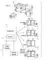
- FIGs. 1 and 7 illustrates the invention in block diagram form.
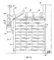
- a cage rack 22, shown schematically, carries a number of individual animal cages 24.
- the rack has internal ducting as explained hereinafter, to supply ventilation air for respiration and to pass spent air through to an exhaust.
- the ventilation air flow aspects are illustrated in Figs. 1 and 7 by a supply blower 32 and exhaust blower 34; however it should be appreciated that other types of relatively positively pressurized air source facilities and relatively negatively pressurized exhaust facilities can be used to produce a current of ventilation air for respiration.
- a source 42 of CO 2 gas shown schematically as a pressurized gas cylinder is coupled by a valve 44 to the air supply and is activated by a controller 50 to supply CO 2 gas to the cage rack in lieu of ventilation air for respiration.
- the CO 2 gas thereby displaces oxygen necessary for respiration and euthanizes the animals.
- the CO 2 gas is supplied in at least two phases and then flushed out, by switching from ventilation of the individual cages with room air (or a similar source containing oxygen) to CO 2 gas. The sequencing of the phases is fully automated.
- Controller 50 can be a programmable logic controller (PLC), available from various suppliers including Allen Bradley, TI, GE, etc.
- PLC programmable logic controller
- the programmable controller operates to advance through states in which the outputs are varied as a function of inputs from switches and sensors, and the passage of time as determined by an internal clock.
- the inputs and outputs can involve switch closures, digital or analog signals and the like.
- the controller 50 advances through phases including (1) a CO 2 gas insufflation phase during which the concentration of CO 2 gas is increased from ambient levels, progressively displacing oxygen; (2) a CO 2 gas exposure or soak phase in which the animals are exposed to the gas in a lethal concentration; and (3) a purge phase wherein the CO 2 gas is removed from the ventilated rack.
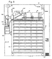
- the ventilated rack 24 is one of a number of racks used for the high density housing of laboratory animals.
- Each rack is normally coupled to ventilation facilities 60, for example including a supply conduit 62 and an exhaust conduit 64. These may be coupled to the rack through local blowers or directly, and may have associated valves and dampers (not shown) for balancing the supply pressure and exhaust suction.
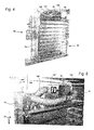
- each cage box 24 fits into a space in the rack 22, for example with flanges along the top edges of an air impervious box engaging flanges 71 for holding the boxes in position under openings 73 in shelves 74.
- the openings 73 lead into internal ducts for supply and exhaust that extend adjacent to one another along the length of the hollow shelves 74.
- the supply and exhaust ducts in the shelves are in communication with similar ducts in hollow end walls 76, and the end walls have openings or couplings 78 where coupled to powered supply and exhaust facilities. It is also possible to have the normal ventilation air supply from the ambient room air into the system, or to vent from the system into the ambient, but connections for remote supply and exhaust venting are preferred, as are powered local blowers and high performance particle filtering such as HEPA filters.
- Figs. 3 and 9 illustrate an exemplary succession from the normal ventilation state 81 to the insufflation phase 83, soak phase 85 and resumed ventilation state 87.
- the invention can be applied to an animal housing system as an operating subsystem.
- the euthanasia facilities are provided so as to coupled to a rack 22 when needed.
- a cage rack 24 as in Figs. 2 or 8 can be detached from its connections to conduits 62, 64, and wheeled into position for engagement with a detachable subsystem as shown in Figs. 4, 5, 10 and 11.
- the respective elements of the system as shown include the ventilation system having at least an air source conduit 62 and air exhaust conduit 64 sufficient for bringing supply air for respiration of animals and removing exhaust air.
- the cage rack or its detachable ventilation subsystem include one or more blowers 32, 34, preferably one for supply and one for exhaust.
- the cage rack 24 supports a plurality of animal cages 22.
- the cages each comprise a box shaped enclosure with air impermeable material at least partly surrounding a housing area for the animals.
- the support rack and animal cages are configured such that when the cages 22 are placed in said support rack 24, the cages are coupled between the air source and air exhaust conduits 62, 64.
- the cages are disposed in an ventilation air path that passes through hollow ducting in the cage rack, including the shelves, into the cages from supply opening in the shelves, and back from the cages into openings leading into the exhaust ducts in the shelves and in due course to the exhaust conduit 64. This route of air passing through the ventilation system is the same route whereby the cage rack 22 normally supplies occupants of the animal cages with air for respiration.
- a supply of gas is coupled to the rack 22 in association with the air source flow path from the air inlet conduit 62.
- the gas supply 42 is coupled through a controllable valve 44, which in turn is electrically controlled from the programmable controller 50.
- Controller 50 also controls the operation of the inlet and/or outlet blowers 32, 34 and any flow regulating valves that are operable to stop, wherein the controllable valve is operable to displace at least part of said air for respiration, for at least one of anesthetizing and asphyxiating said animals while disposed in said cages in said support rack.
- the composition used as the means for euthanizing the animals is CO 2 gas and the gas is introduced in stages.
- the gas is introduced at a concentration effective to anesthetize the animals, i.e., to render the animals sleepy and then unconscious.
- the next stage is displace air from the cages to the extent that the concentration of CO 2 gas is lethal, and to hold the concentration for a sufficient time to asphyxiate the animals.
- the stages are timed by operation of the programmable controller 50.
- the CO 2 gas is confined because the cages comprise impermeable boxes suspended from the hollow shelves with internal ducts or conduits that lead to the supply and exhaust conduits and blowers, but in a manner that is controllable by controller 50.
- the exemplary supply of gas comprises pressurized CO 2 gas
- other gases are not excluded, to be used instead of or in addition to the CO 2 gas.
- Other oxygen displacing gases such as nitrogen are possible.
- nitrogen can be injected prior to the oxygen displacing gas.
- CO 2 gas is advantageous because it is more dense than air.
- one or more electrically operated gate valves can be coupled to the controller at the inlet and outlet conduits 62, 64 for controllably coupling one of the respiration air and the supply of gas to the air source conduit.
- check valves associated with the exhaust arrangements can ensure that in the venting phase the CO 2 gas is not released into the ambient air and instead is carried away.
- additional safety elements for ensuring exhaust of the CO 2 gas include a thimble connection with the downstream exhaust conduits, and an optional supplementary exhaust inlet to remove air at a low elevation in the room, etc.
- the controller is coupled at least to the controllable valve operable to inject the CO 2 gas, and also controls the blowers 32, 34 and/or associated valves to selectively activate and deactivate the air (or gas) flow into the ventilation pathways leading to the animal cages, as well as the exhaust flow from the cages to a downstream point of discharge.
- the controller is programmed and coupled to operate the blowers and/or valves in a series of successive operations, shown schematically in Fig. 3.
- the controller comprises a timer 110, for stepping through the series of successive operations in a timed sequence.
- the sequence can be more or less variable and programmed to effect two or more different cycles, selected by operation of switch inputs from user inputs 110, and/or as a function of sensed conditions of gas pressure, flow and the like via sense inputs 112.
- the blowers 32, 34 are activated and deactivated by the controller, in order to start and stop flow.
- stopping flow is equivalent to operating a gate valve to close off the associated air/gas passageway.
- the controller effects a coordinated activation and deactivation of flows in a sequence.
- the sequence comprises replacing ventilation air as the source of flow with the CO 2 or other operative gas for a sufficient time to render lethal the atmosphere in the animal cages.
- the preferred sequence comprises timed periods of insufflation 83 wherein the concentration of CO 2 gas is increased, soak 85 wherein a lethal concentration is maintained for an effective period of time, and venting 87, wherein ventilation flow is resumed for a sufficient time to clear the CO 2 gas to the extent that it is safe to remove the cages 24 from the rack 22, and ensure that the process was effective, finally exposing the ambient atmosphere to the contents of the cages.
- the time periods chosen are planned for initially anesthetizing the animals, i.e., rendering the animals unconscious before the concentration of CO 2 is such that the atmosphere is not breathable. This eliminates or substantially reduces stress on the animals.
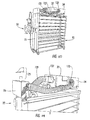
- Figs. 4 and 5 as well as Figs. 10 and 11 illustrate a practical embodiment of the invention.
- the supply and exhaust blowers 32, 34 are normally kept suspended in a fixture that is removably coupled by flexible ducts 120, 122 to the cage rack 22, preferably to a hollow end wall 76 coupled to internally ducted shelves as also shown in Fig. 3.
- the arrangement can lowered from a hook and bracket arrangement 125 mounted on a building wall such that a rack 22 can be wheeled into position at which the fixture is conveniently deployed, e.g., at least the connecting portions and optionally also the blowers 32, 34, are lowered onto the cage rack.
- With power coupled to the blowers 32, 34 through the controller 50 normal ventilation ensues.
- a gas cycle begins by a user initiating a "start" input to controller 50 (e.g., selecting an operation and activating a key-operated switch). There is a brief interruption of the air stream as the air supply blower 32 is shut off.
- the supply duct 62 is decoupled by closing a gate valve 127.
- a gate valve can be located upstream or downstream of the supply blower 32 and in the embodiment shown is between the supply blower and the ducting in the cage rack 22.
- controller opens the CO 2 gas supply valve to insert CO 2 gas at a point downstream of the gate valve and leading into the air supply ducting in rack 22.
- the air stream into the individual cages resumes through the inlets 73, but now the incoming stream is CO 2 gas rather then air for respiration. Meanwhile, the exhaust blower 34 continues to operate.
- the CO 2 gas stream mixes with the air in the cage boxes 24. Over a period of time of suffusing the cage boxes with CO 2 gas, more and more oxygen is displaced from the cage boxes. The concentration of CO 2 in the cages increases and the concentration of oxygen decreases. As the concentration of CO 2 gas increases, the gas acts as a general anesthetic, eventually putting the animals into a deep sleep. This phase is continued for a time sufficient to anesthetize the animals and to substantially replace the air in the cage boxes with CO 2 gas. Over a period of about two minutes, the cage box is progressively charged with CO 2 gas. There is some turbulence due to continuing flow.
- CO 2 gas is heavier than air, tending to accumulate in the bottoms of the cages and to float any remaining oxygen carrying air toward the tops of the cage boxes.
- the cage boxes are mounted underneath the ducted shelves. Thus the floating oxygen carrying air is extracted into the exhaust ducts as the CO 2 gas settles.
- the foregoing insufflation phase is maintained for a sufficient time to replace the air in the cages with CO 2 gas.
- the period can be longer or shorter depending on the rate of gas supply and through current. Two minutes is an example.
- the controller 50 then steps to the next stage of operation, which is a soak or dwell phase during which the cage boxes are kept charged with lethal levels of CO 2 gas. In this soak phase, the controller 50 turns off the exhaust blower.
- the controller 50 can close the CO 2 gas supply valve 44 at the same time, leaving the cage boxes in a stagnant air condition with a high concentration of CO 2 gas. It is also possible to permit the CO 2 gas supply to remain open or to remain open for a time.
- the soak phase is timed to last, for example for 15 minutes, during which the dense CO 2 gas settles to the cage bottoms and the animals are completely euthanized by asphyxiation.
- the asphyxiation is complete in a shorter time, but it is advantageous to extend the soak phase for a more than sufficient time so as to euthanize the unconscious animals with a very high degree of effectiveness.
- the controller 50 After the timed CO 2 gas soak interval, the controller 50 enters a purge or venting phase.
- the controller opens the air supply gate valve 127 and couples power to the exhaust blower 34.
- the air supply blower 32 is powered as well.
- Operating the exhaust blower 34 before the supply blower for a time produces a negative pressure that tends to draw room air into the exhaust path, as well as air from the supply conduit 62, producing little or no leakage of CO 2 gas into the room.
- the CO 2 gas is discharged from the cages into the exhaust ducts.
- the supply blower 32 is used for this venting phase, at least after a delay, so that the CO 2 gas is dependably flushed from the cage boxes into the exhaust.
- a timed interval of five minutes is generally sufficient to clear the CO 2 gas from the cage boxes.
- the controller can operate a warning light or buzzer to indicate that the cycle has been completed. At that point, the cage boxes can safely be removed for processing of the euthanized animals.
- the controller is programmed to effect an insufflation phase wherein the supply of gas is substituted said air for respiration during a first time period that generally accomplishes general anesthesia, and a timed for distribution of the gas in a soak phase that generally asphyxiates the animal subjects.
- the cage support rack is detachable from an existing set of air supply and air exhaust conduits 62, 64 and coupleable to a set of air supply and air exhaust conduits of a fixture in communication with the supply of gas and comprising the controllable gas valve. After completion of a euthanasia cycle as described, the cage rack is ready to resume use as an animal housing system as shown in Fig. 2.
- the controller 50 is generally contained in a wall mounted cabinet having indicators for gas pressure, indicator lights for status indications and switch controls for operation.
- the face of the controller cabinet defines a control panel and indicates on/off status, the selected operation and the present phase in the operation.
- the controller includes indications of when the process is operated and when the process has been completed, for example a green light to show that the cages can safely be removed, e.g., for disposal of animal carcasses.
- a switch key is used for activation.
- the PLC 50 turns off the supply blower 32 which has been providing cages with respiration air, such as HEPA-filtered room air; activates closure of the gate damper valve 127, thereby isolating the supply blower conduit so as to prevent backflow of gas along the supply conduit.
- a solenoid valve is opened, allowing CO2 to enter the supply plenum 76, flowing from there to the shelf ducts and into the cages 24.
- the solenoid valve can be mounted in series with a high flow pressure regulator 132, a manual shutoff valve 134, and a quick connect fitting for coupling with a pressurized gas cylinder 42 (shown in Figs. 1 and 7).
- the exhaust blower 34 preferably remains on for almost the entire insufflation phase and aids gas distribution into the cages 24.
- the PLC turns off the exhaust blower 34.
- the solenoid valve 44 controlling CO 2 gas inflow is closed. It is also possible to continue the CO 2 gas inflow pressure, although the exhaust blower is off, but it should be appreciated that leakage gas could be released into the room.
- a floor inlet 142 can be provided in the general area to extract air near the floor level containing CO 2 gas. Normally with no flow being driven by the blowers 32, 34, the CO 2 gas in the cages settles to the lowest elevation and remains at a lethal concentration.
- the animals in the cages 24 are exposed to CO 2 gas during the insufflation phase, and to lethal concentrations of CO 2 gas in the subsequent soak phase, which is held for a sufficient time to ensure euthanasia, e.g., 15 minutes.
- the gate damper 127 is opened. Both the exhaust and supply blowers 34, 32 are activated. Room air is drawn in through the filters associated with the inlet conduit 62, passed through the respective ducts and cages to the exhaust conduit 64, and purges the cages of CO 2 gas.
- the system of the invention can be ducted to an outdoor discharge, or can be simply ducted to the building HVAC system exhaust line, provided the capacity is such that the volume of CO 2 gas is appropriately diluted and/or safely routed.
- the exhaust is preferably passed, through a thimble connection to prevent local CO 2 gas release into the room air.
- the controller 50 preferably can be set to different timed cycles depending on the operator's selection, e.g., programmed to selectively execute up to six different cycles. The duration of each cycle can be varied.
- the valves and the blowers can be selectively opened/closed or turned on/off during these cycles.
- the valves also can be arranged to open by incremental or proportional amounts, and the blowers can be operated at less than full power or at selected rates in a range of available variable speeds, in phases of operation maintained by outputs from controller 50.
- a two minute insufflation period, and a 15 minute soak cycle were found to be effective for euthanizing mice greater than seven days of age. Neonates were found to require excessive soak time and/or substantial use of CO 2 gas.
- mice or other animals need not be removed from their home cage to another cage. No additional animals typically are added to the cage prior to euthanasia. There is little unusual activity. As a result of these factors, animal stress is substantially eliminated and personnel labor is reduced compared to other techniques. As described above, the system incorporates a number of features to ensure sexual animal treatment and personnel safety and convenience.
- the CO 2 gas application and control apparatus has a standard exhaust blower box with a keyed plug and a modified supply blower box. Neither blower box is standard to any rack, making it unlikely that the CO 2 gas system can be inadvertently engaged to a cage rack by an inexperienced worker.
- Modifications to the supply blower and conduit include the added supply gate valve 127 and the high flow pressure regulator valve 136 that has been specially configured and sized to dispense CO 2 gas at a flow rate and pressure that approximates the conditions at which the normal supply blower would provide respiration air if activated.
- the safety features built in to prevent dangerous operating conditions include two pressure sensing switches (one at the supply and one at the exhaust) to monitor the integrity of the supply and exhaust connections during the respiration air ventilation state.
- pressure monitoring is known in caging systems and can generate an alarm condition if pressure and suction levels suggest a blockage or leak.
- an alarm state in these pressure and suction levels is sensed by controller 50.
- the controller is programmed so as not to allow a CO 2 gas cycle to commence if a connection problem or anomaly is sensed.
- the controller can refrain from commencing a cycle.
- the available gas supply pressure is inadequate, if a connection line is decoupled or leaking, etc., the cycle is not started and a fault light or alarm can so indicate.
- the position of the gate valve 127 can be sensed using a limit switch contact closure coupled to controller 50. If the gate valve 127 is not sensed to be closed, the controller can refrain from opening control valve 132 for release of CO 2 gas, thereby preventing backflow of CO 2 gas on the supply side.
- the CO 2 gas valve is spring biased to close. In the event of a power failure, the CO 2 gas valve closes immediately. When power resumes, the controller assumes a default animal-maintenance starting state. An alarm light can be activated to indicate this occurrence as another error condition. For humane reasons, it is desirable in the event of a commence euthanasia cycle, to complete the cycle and not to risk the possibility of injuring but not euthanizing the animals. Also for this reason, the available CO 2 gas volume can be sensed, e.g., by available pressure or by tank weight, and no cycle commenced if the pressure or volume appear to be marginal for completing a cycle until the CO 2 tank is changed.
- the PLC monitors the safety features as inputs, together with user selections and switches.
- the PLC outputs closures for application of power to the valves and blowers or to motor starter relays or solid state switches, etc.
- the PLC sequence is selected in part from programming and in part from user selection switches, and an internal clock is used for timing the sequencing from one selected stage or phase to the next.
- the PLC program can be arranged to be downloaded remotely over a phone modem (not shown).
- the program can be contained in nonvolatile memory such as a programmed ROM.
- the control of the euthanasia system can be one of a number of control aspects associated with controls in an animal housing facility, e.g., as subroutines in a larger control scheme run on a PC or the like.
- the initial setup procedure includes adjusting the CO 2 gas pressure.
- the CO 2 gas pressure from the tank is set to a nominal level, e.g., 8 PSI, that is higher than the regulated operational pressure that will be used.
- the controller 50 has a selector switch for selecting the program or sequence to be operated, and for setup the selector is switched, e.g., to Program #1.
- the operator turns the "start" key switch, opening gas valve 44.
- the high flow rate regulator valve 132 is manually adjusted, preferably quickly, to get an 0.20 to 0.30" H 2 O column pressure (preferably 0.20 - 0.25") on the magnehelic pressure meter of the controller 50.
- the gas system is then set up.
- the operator presses "stop” and the euthanasia system is ready to be coupled to a cage rack.
- a standard unmodified cage rack is wheeled into position under the euthanasia transition hookups, normally suspended using wall bracket arrangement 125.
- the transition is dropped from the bracket and clamped in place on the rack with quick connect clamps that correspond to the standard ventilation hookups on the racks.
- the supply and exhaust blowers are powered and operate to ventilate the cage boxes in the rack.
- the operator should verify that supply air pressure is close to nominal (e.g., 0.2 ⁇ 0.25" H 2 O) and exhaust pressure is close to nominal (e.g., 0.15 - 0.20" H 2 O). If not, the respective connections should be checked and necessary damper adjustments made.
- the controller 50 will decline to initiate operation for the euthanasia cycle if sensed pressures are not near nominal.
- variable speed exhaust blower and/or damper arrangement can be substituted for a simple on/off exhaust blower arrangement.
- the controller operates the exhaust blower at a higher level in the maintain state and at a lower level at the beginning of the euthanasia cycle, so as to match the lower CO 2 injection pressure.
- the CO 2 gas is handled at pressure differentials that are comparable to the pressure differentials in the ventilation air "maintain" state.
- the high flow rate - low pressure regulator valve 136 provides CO 2 gas in lieu of oxygen carrying air during the euthanasia cycle, but at very similar flow conditions. This is an improvement over injecting CO 2 gas simply by opening flow to orifices from a pressurized gas supply into the ventilation air supply or into the individual shelf ducts. Releasing gas at orifices near the cages can cause rapid substantial cooling (due to the gas pressure drop), noise and other adverse effects.
- CO 2 gas euthanasia technique may not be suitable for infant mice, due to the long CO 2 gas soak time that might be necessary for complete effectiveness.
- certain genetically altered or weakened animals, being more sensitive may advantageously be subjected to a slower gas feed to further minimize stress.
- the rack In the maintain state, the rack can remain in place and coupled to the inoperative euthanasia system while being supplied with ventilation air for respiration. This state can remain as long as desired.
- connections should be checked and pressures monitored before pressing the start button, and status indicators should be observed when attempting to commence a cycle, to take due note of fault indications requiring attention.
- the controller 50 monitors operations and provides the necessary outputs to complete the cycle without continued attention.
- a high density animal housing system with an air source conduit and an air exhaust conduit is disclosed which is normally coupled to one or more ventilating animal cage racks through standard inlet/outlet fittings.
- a euthanasia fixture is coupled into the standard inlet/outlet fittings and selectively and sequentially operates valves and/or blowers to switch from supply of respiration air to a gas supply, to open and close the flow to the exhaust and to resume ventilation afterwards, for venting.
- the sequence is timed and controlled by a programmable controller that activates the associated blowers and valves automatically to follow a user selected sequence.
- the system anesthetizes and then euthanizes the animals via the same flow conduits that otherwise supply respiration air, requiring no rack modifications and little if any human attention other than to couple the rack to the ventilation system at the euthanasia fixture.
- Operator inputs allow selection among sequences.
- Status sensing inputs prevent initiation or continuation of a cycle in the event of certain faults.
Landscapes
- Life Sciences & Earth Sciences (AREA)
- Engineering & Computer Science (AREA)
- Food Science & Technology (AREA)
- Environmental Sciences (AREA)
- Zoology (AREA)
- General Health & Medical Sciences (AREA)
- Clinical Laboratory Science (AREA)
- Animal Behavior & Ethology (AREA)
- Animal Husbandry (AREA)
- Biodiversity & Conservation Biology (AREA)
- Health & Medical Sciences (AREA)
- Housing For Livestock And Birds (AREA)
- Accommodation For Nursing Or Treatment Tables (AREA)
Applications Claiming Priority (1)
| Application Number | Priority Date | Filing Date | Title |
|---|---|---|---|
| US10/890,726 US20060011143A1 (en) | 2004-07-14 | 2004-07-14 | Laboratory animal housing with euthanizing function |
Publications (2)
| Publication Number | Publication Date |
|---|---|
| EP1616482A2 true EP1616482A2 (de) | 2006-01-18 |
| EP1616482A3 EP1616482A3 (de) | 2006-05-10 |
Family
ID=35057077
Family Applications (1)
| Application Number | Title | Priority Date | Filing Date |
|---|---|---|---|
| EP05106487A Withdrawn EP1616482A3 (de) | 2004-07-14 | 2005-07-14 | Versuchstierbehausung mit Euthanasierfunktion |
Country Status (2)
| Country | Link |
|---|---|
| US (1) | US20060011143A1 (de) |
| EP (1) | EP1616482A3 (de) |
Cited By (8)
| Publication number | Priority date | Publication date | Assignee | Title |
|---|---|---|---|---|
| EP2087787A3 (de) * | 2007-12-27 | 2009-11-25 | TECNIPLAST S.p.A. | Haltekäfig für Labortiere |
| US8181603B2 (en) | 2008-08-08 | 2012-05-22 | Tecniplast S.P.A. | Apparatus and method for changing laboratory animal cages or other operations |
| CN101485294B (zh) * | 2008-12-19 | 2012-05-30 | 苏州市苏杭科技器材有限公司 | 生物安全笼盒系统 |
| CN102784013A (zh) * | 2012-09-06 | 2012-11-21 | 天津开发区合普工贸有限公司 | 一种惰性气体小动物快速休克处置设备 |
| CN104620995A (zh) * | 2015-03-02 | 2015-05-20 | 济南大学 | 一种用于养殖场的养殖物作息控制系统及方法 |
| US9078451B2 (en) * | 2013-03-01 | 2015-07-14 | Brian Stevens | Method for euthanizing animals |
| WO2017020931A1 (de) * | 2015-07-31 | 2017-02-09 | Linco Food Systems A/S | Vorrichtung, anordnung und verfahren zum betäuben von geflügeltieren |
| CN115399244A (zh) * | 2022-08-30 | 2022-11-29 | 温州医科大学 | 一种多功能的实验动物安乐死ivc |
Families Citing this family (40)
| Publication number | Priority date | Publication date | Assignee | Title |
|---|---|---|---|---|
| US20070169715A1 (en) | 2004-12-13 | 2007-07-26 | Innovive Inc. | Containment systems and components for animal husbandry |
| US7527020B2 (en) | 2004-12-13 | 2009-05-05 | Innovive, Inc. | Containment systems and components for animal husbandry |
| US8082885B2 (en) * | 2004-12-13 | 2011-12-27 | Innovive, Inc. | Containment systems and components for animal husbandry: rack module assembly method |
| US20070181074A1 (en) * | 2004-12-13 | 2007-08-09 | Innovive Inc. | Containment systems and components for animal husbandry |
| US7661392B2 (en) * | 2004-12-13 | 2010-02-16 | Innovive, Inc. | Containment systems and components for animal husbandry: nested cage bases |
| US7874268B2 (en) * | 2004-12-13 | 2011-01-25 | Innovive, Inc. | Method for adjusting airflow in a rodent containment cage |
| US7739984B2 (en) * | 2004-12-13 | 2010-06-22 | Innovive, Inc. | Containment systems and components for animal husbandry: cage racks |
| US8156899B2 (en) | 2004-12-13 | 2012-04-17 | Innovive Inc. | Containment systems and components for animal husbandry: nested covers |
| US7734381B2 (en) * | 2004-12-13 | 2010-06-08 | Innovive, Inc. | Controller for regulating airflow in rodent containment system |
| US7954455B2 (en) | 2005-06-14 | 2011-06-07 | Innovive, Inc. | Cage cover with filter, shield and nozzle receptacle |
| US20070193527A1 (en) * | 2005-10-03 | 2007-08-23 | Richard Verhage | Ventilated animal cage assembly |
| WO2007120973A2 (en) | 2006-02-10 | 2007-10-25 | Air Products And Chemicals, Inc. | Process and apparatus for depopulating groups of animals |
| JP4948060B2 (ja) * | 2006-07-06 | 2012-06-06 | オリンパス株式会社 | 生体観察装置 |
| US20110061600A1 (en) * | 2006-08-17 | 2011-03-17 | Innovive, Inc. | Containment systems and components for animal husbandry |
| US20080134984A1 (en) * | 2006-10-13 | 2008-06-12 | Conger Dee L | Containment cage liners for animal husbandry |
| US9155283B2 (en) * | 2007-04-11 | 2015-10-13 | Innovive, Inc. | Animal husbandry drawer caging |
| WO2009058557A2 (en) | 2007-10-12 | 2009-05-07 | Euthanix Corp. | Method and apparatus for euthanizing animals |
| WO2009076335A1 (en) * | 2007-12-10 | 2009-06-18 | The Cooper Union For The Advancement Of Science And Art | Gas delivery system for an animal storage container |
| US20100006522A1 (en) * | 2008-07-02 | 2010-01-14 | Hage Richard P Ver | Animal housing unit and racking system |
| EP2323729A4 (de) * | 2008-08-12 | 2016-05-25 | Aspect Magnet Technologies Ltd | System zur anästhesierung bei anpassung der temperatur von säugern und verfahren dafür |
| WO2010054257A2 (en) | 2008-11-07 | 2010-05-14 | Innovive, Inc. | Rack system and monitoring for animal husbandry |
| ITMI20091045A1 (it) * | 2009-06-12 | 2010-12-13 | Tecniplast Spa | Scaffale ventilato, particolarmente per stabulari, dotato di filtro anti-particolato |
| KR101139353B1 (ko) * | 2009-09-24 | 2012-04-26 | 건국대학교 산학협력단 | 실험동물용 안락사 장치 및 안락사 방법 |
| US20110139086A1 (en) * | 2009-12-16 | 2011-06-16 | David Burgener | Method, Apparatus, and System for Euthanizing Large Numbers of Animals with Solid Carbon Dioxide |
| JP5952287B2 (ja) | 2010-10-11 | 2016-07-13 | イノビーブ,インコーポレイティド | げっ歯動物収容ケージ監視装置及び方法 |
| US20120272919A1 (en) * | 2011-04-26 | 2012-11-01 | The University Of Utah | Animal euthanasia systems and methods |
| CA2880064C (en) * | 2012-07-23 | 2019-09-17 | Lenderking Caging Products | Cage for laboratory animal |
| EP4691229A3 (de) | 2013-07-01 | 2026-04-15 | Innovive, LLC | System zur überwachung von käfigregalen |
| JP6184836B2 (ja) * | 2013-10-30 | 2017-08-23 | 東洋熱工業株式会社 | 動物飼育ラック |
| EP3177134B1 (de) | 2014-07-25 | 2022-08-17 | Innovive, Inc. | Strukturen und verfahren zur bereicherung von tiereinhausungen |
| US11272686B2 (en) * | 2015-05-11 | 2022-03-15 | Bigcity Design Pty Ltd | Modular animal accommodation |
| US20170312066A1 (en) * | 2015-11-30 | 2017-11-02 | The University Of Notre Dame Du Lac | Versatile inhalation anesthesia platform for small animal surgery |
| USD814719S1 (en) * | 2016-07-21 | 2018-04-03 | AUTO ELEX Co., LTD | Incubator for animal |
| JP2018046792A (ja) * | 2016-09-23 | 2018-03-29 | オネストスター エンタープライゼズ リミテッド | 飼育ケージホルダー |
| JP7051883B2 (ja) | 2016-10-28 | 2022-04-11 | イノバイブ, インコーポレイテッド | 代謝ケージ |
| NL2026492B1 (en) * | 2020-09-17 | 2022-05-23 | Kiezebrink Harm | A method of preparing an animal for slaughter |
| CN112690312A (zh) * | 2020-12-23 | 2021-04-23 | 程士菊 | 一种昏迷放血的二氧化碳杀畜装置 |
| CN113279996A (zh) * | 2021-06-15 | 2021-08-20 | 河南艾牧智能设备有限公司 | 环控器风机控制系统的风机均衡运行的方法 |
| CN113767856B (zh) * | 2021-09-02 | 2023-01-17 | 温州医科大学 | 一种多功能的实验动物处理装置 |
| CN115968796A (zh) * | 2022-12-28 | 2023-04-18 | 中国人民解放军总医院第一医学中心 | 一种非人灵长类动物手术用护理装置 |
Citations (5)
| Publication number | Priority date | Publication date | Assignee | Title |
|---|---|---|---|---|
| US4343261A (en) | 1979-09-18 | 1982-08-10 | Thomas William R | Animal caging system |
| US4402280A (en) | 1980-11-12 | 1983-09-06 | Thomas William R | Animal caging system |
| US4690100A (en) | 1985-10-22 | 1987-09-01 | Thoren Caging Systems, Inc. | Ventilated animal housing and service system with cage filter covers |
| US4941431A (en) | 1988-12-14 | 1990-07-17 | Anderson Francis G | System for handling laboratory animals |
| US5044316A (en) | 1990-03-28 | 1991-09-03 | Thoren Caging Systems, Inc. | Ventilated animal caging system with cage racks and filter covers including valves operable by rack |
Family Cites Families (17)
| Publication number | Priority date | Publication date | Assignee | Title |
|---|---|---|---|---|
| US1849194A (en) * | 1930-11-10 | 1932-03-15 | Mccurrie Matthew | Lethal apparatus |
| US3006339A (en) * | 1958-10-06 | 1961-10-31 | Shampaine Ind Inc | Oxygen tents |
| US3356087A (en) * | 1966-02-10 | 1967-12-05 | Yolan R Guttman | Euthanasia apparatus |
| US3367308A (en) * | 1966-04-26 | 1968-02-06 | Nasa Usa | Exposure system for animals |
| US3505989A (en) * | 1967-05-29 | 1970-04-14 | Johnson & Johnson | Controlled environmental apparatus |
| GB1521700A (en) * | 1975-12-11 | 1978-08-16 | Universities Federation For An | Euthanasia of animals |
| US4305347A (en) * | 1980-04-29 | 1981-12-15 | The Baker Company, Inc. | Inhalation toxicology chamber |
| DE3805158A1 (de) * | 1988-02-15 | 1989-08-24 | Wago Verwaltungs Gmbh | Reihenklemme zur zweileiter-stromversorgung von elektrischen oder elektronischen bauelementen, insbesondere initiatoren |
| US5163380A (en) * | 1990-08-09 | 1992-11-17 | United States Of America | Method and apparatus for assessing metabolic behavioral and physiological status of animals |
| US5220882A (en) * | 1991-11-05 | 1993-06-22 | Jenkins Thomas S | Pet treatment door |
| US5954013A (en) * | 1996-09-18 | 1999-09-21 | Lab Products Inc. | Ventilated cage and rack system |
| US5865144A (en) * | 1997-08-29 | 1999-02-02 | Semenuk; Michael | Ventilated cage for laboratory animal |
| US6308660B1 (en) * | 1999-06-17 | 2001-10-30 | Allentown Caging Equipment Co., Inc. | Bio-containment animal cage system |
| US6352076B1 (en) * | 1999-07-01 | 2002-03-05 | Larry G. French | Anesthesia induction chamber for small animals |
| US6776158B1 (en) * | 2001-07-26 | 2004-08-17 | Euthanex Corporation | System for anesthetizing laboratory animals |
| US7503323B2 (en) * | 2002-02-20 | 2009-03-17 | Xenogen Corporation | Multiple output anesthesia system |
| US20050022808A1 (en) * | 2003-02-05 | 2005-02-03 | Caplette Joseph Raymond | Rodent euthanasia machine |
-
2004
- 2004-07-14 US US10/890,726 patent/US20060011143A1/en not_active Abandoned
-
2005
- 2005-07-14 EP EP05106487A patent/EP1616482A3/de not_active Withdrawn
Patent Citations (5)
| Publication number | Priority date | Publication date | Assignee | Title |
|---|---|---|---|---|
| US4343261A (en) | 1979-09-18 | 1982-08-10 | Thomas William R | Animal caging system |
| US4402280A (en) | 1980-11-12 | 1983-09-06 | Thomas William R | Animal caging system |
| US4690100A (en) | 1985-10-22 | 1987-09-01 | Thoren Caging Systems, Inc. | Ventilated animal housing and service system with cage filter covers |
| US4941431A (en) | 1988-12-14 | 1990-07-17 | Anderson Francis G | System for handling laboratory animals |
| US5044316A (en) | 1990-03-28 | 1991-09-03 | Thoren Caging Systems, Inc. | Ventilated animal caging system with cage racks and filter covers including valves operable by rack |
Cited By (12)
| Publication number | Priority date | Publication date | Assignee | Title |
|---|---|---|---|---|
| EP2087787A3 (de) * | 2007-12-27 | 2009-11-25 | TECNIPLAST S.p.A. | Haltekäfig für Labortiere |
| US8047160B2 (en) | 2007-12-27 | 2011-11-01 | Tecniplast S.P.A. | Keeping cage for laboratory animals |
| US8181603B2 (en) | 2008-08-08 | 2012-05-22 | Tecniplast S.P.A. | Apparatus and method for changing laboratory animal cages or other operations |
| CN101485294B (zh) * | 2008-12-19 | 2012-05-30 | 苏州市苏杭科技器材有限公司 | 生物安全笼盒系统 |
| CN102784013A (zh) * | 2012-09-06 | 2012-11-21 | 天津开发区合普工贸有限公司 | 一种惰性气体小动物快速休克处置设备 |
| CN102784013B (zh) * | 2012-09-06 | 2015-01-28 | 天津开发区合普工贸有限公司 | 一种惰性气体小动物快速休克处置设备 |
| US9078451B2 (en) * | 2013-03-01 | 2015-07-14 | Brian Stevens | Method for euthanizing animals |
| CN104620995A (zh) * | 2015-03-02 | 2015-05-20 | 济南大学 | 一种用于养殖场的养殖物作息控制系统及方法 |
| WO2017020931A1 (de) * | 2015-07-31 | 2017-02-09 | Linco Food Systems A/S | Vorrichtung, anordnung und verfahren zum betäuben von geflügeltieren |
| US10136654B2 (en) | 2015-07-31 | 2018-11-27 | Linco Food Systems A/S | Device, assembly, and method for stunning poultry |
| RU2695882C1 (ru) * | 2015-07-31 | 2019-07-29 | ЛИНКО Фуд Системс А/С | Устройство, установка и способ оглушения птицы |
| CN115399244A (zh) * | 2022-08-30 | 2022-11-29 | 温州医科大学 | 一种多功能的实验动物安乐死ivc |
Also Published As
| Publication number | Publication date |
|---|---|
| US20060011143A1 (en) | 2006-01-19 |
| EP1616482A3 (de) | 2006-05-10 |
Similar Documents
| Publication | Publication Date | Title |
|---|---|---|
| EP1616482A2 (de) | Versuchstierbehausung mit Euthanasierfunktion | |
| US6776158B1 (en) | System for anesthetizing laboratory animals | |
| US20090126647A1 (en) | Method and Apparatus for Euthanizing Animals | |
| EP3310178B1 (de) | Verfahren und system zum betäuben und/oder töten von tieren | |
| US4898713A (en) | Process for sterilizing a tight enclosure and installation for performing this process | |
| BRPI0715607A2 (pt) | mÉtodos para tratar carga viva com uma mistura gasosa e para tratar lote de carga viva em um veÍculo tendo uma Área de carga adaptada para transportar carga viva | |
| BRPI0613961B1 (pt) | Structure and process for curing tobacco | |
| JP2010511447A (ja) | 補給空気を調節下に供給するための方法および装置 | |
| BR0112426B1 (pt) | Aparelho de fumigação, e, método para fumigar produtos | |
| US10757949B1 (en) | Poultry stunning system and method | |
| AU2015404926A1 (en) | Device, assembly, and method for stunning poultry | |
| JP4490538B2 (ja) | ホルムアルデヒド分解装置、ホルムアルデヒド分解用触媒を備えた空調機、ホルムアルデヒド発生装置と分解装置を備えた燻蒸システム及びホルムアルデヒド発生・分解装置 | |
| US11253669B2 (en) | Anesthesia breathing system and a method and kit for drying an anesthesia breathing system | |
| KR20230076752A (ko) | 축사 관제 시스템 | |
| US4921675A (en) | Biocidal gas sterilizer | |
| KR101962350B1 (ko) | 버섯재배사의 자동 환기 시스템 | |
| JP2010094138A (ja) | 動物飼育室の制御装置及びその方法 | |
| JP2010081865A (ja) | 動物飼育室 | |
| JPH11146905A (ja) | オゾン燻蒸殺菌装置 | |
| JP6795756B2 (ja) | アイソレータシステムとアイソレータシステムのエアレーション方法 | |
| JP2020038080A (ja) | 原子力プラントの換気空調システム及び換気空調方法 | |
| JPH0679533B2 (ja) | 薫蒸装置 | |
| JP2005069687A (ja) | 熱老化試験装置 | |
| RU2139024C1 (ru) | Барокамера медицинская гипобарическая | |
| JP2749483B2 (ja) | 養液栽培装置の殺菌装置 |
Legal Events
| Date | Code | Title | Description |
|---|---|---|---|
| PUAI | Public reference made under article 153(3) epc to a published international application that has entered the european phase |
Free format text: ORIGINAL CODE: 0009012 |
|
| AK | Designated contracting states |
Kind code of ref document: A2 Designated state(s): AT BE BG CH CY CZ DE DK EE ES FI FR GB GR HU IE IS IT LI LT LU LV MC NL PL PT RO SE SI SK TR |
|
| AX | Request for extension of the european patent |
Extension state: AL BA HR MK YU |
|
| PUAL | Search report despatched |
Free format text: ORIGINAL CODE: 0009013 |
|
| RAP1 | Party data changed (applicant data changed or rights of an application transferred) |
Owner name: SLOAN-KETTERING INSTITUTE FOR CANCER RESEARCH Owner name: THOREN CAGING SYSTEMS, INC. |
|
| AK | Designated contracting states |
Kind code of ref document: A3 Designated state(s): AT BE BG CH CY CZ DE DK EE ES FI FR GB GR HU IE IS IT LI LT LU LV MC NL PL PT RO SE SI SK TR |
|
| AX | Request for extension of the european patent |
Extension state: AL BA HR MK YU |
|
| AKX | Designation fees paid | ||
| STAA | Information on the status of an ep patent application or granted ep patent |
Free format text: STATUS: THE APPLICATION IS DEEMED TO BE WITHDRAWN |
|
| 18D | Application deemed to be withdrawn |
Effective date: 20061111 |
|
| REG | Reference to a national code |
Ref country code: DE Ref legal event code: 8566 |