EP1615775B1 - Vorrichtung zum halten und nachfüllen einer tintenpatrone für einen farbendruckkopf - Google Patents
Vorrichtung zum halten und nachfüllen einer tintenpatrone für einen farbendruckkopf Download PDFInfo
- Publication number
- EP1615775B1 EP1615775B1 EP04726251A EP04726251A EP1615775B1 EP 1615775 B1 EP1615775 B1 EP 1615775B1 EP 04726251 A EP04726251 A EP 04726251A EP 04726251 A EP04726251 A EP 04726251A EP 1615775 B1 EP1615775 B1 EP 1615775B1
- Authority
- EP
- European Patent Office
- Prior art keywords
- container
- cartridge
- colour
- tanks
- feeding
- Prior art date
- Legal status (The legal status is an assumption and is not a legal conclusion. Google has not performed a legal analysis and makes no representation as to the accuracy of the status listed.)
- Expired - Lifetime
Links
Images


Classifications
-
- B—PERFORMING OPERATIONS; TRANSPORTING
- B41—PRINTING; LINING MACHINES; TYPEWRITERS; STAMPS
- B41J—TYPEWRITERS; SELECTIVE PRINTING MECHANISMS, i.e. MECHANISMS PRINTING OTHERWISE THAN FROM A FORME; CORRECTION OF TYPOGRAPHICAL ERRORS
- B41J2/00—Typewriters or selective printing mechanisms characterised by the printing or marking process for which they are designed
- B41J2/005—Typewriters or selective printing mechanisms characterised by the printing or marking process for which they are designed characterised by bringing liquid or particles selectively into contact with a printing material
- B41J2/01—Ink jet
- B41J2/17—Ink jet characterised by ink handling
- B41J2/175—Ink supply systems ; Circuit parts therefor
- B41J2/17503—Ink cartridges
- B41J2/17513—Inner structure
-
- B—PERFORMING OPERATIONS; TRANSPORTING
- B41—PRINTING; LINING MACHINES; TYPEWRITERS; STAMPS
- B41J—TYPEWRITERS; SELECTIVE PRINTING MECHANISMS, i.e. MECHANISMS PRINTING OTHERWISE THAN FROM A FORME; CORRECTION OF TYPOGRAPHICAL ERRORS
- B41J2/00—Typewriters or selective printing mechanisms characterised by the printing or marking process for which they are designed
- B41J2/005—Typewriters or selective printing mechanisms characterised by the printing or marking process for which they are designed characterised by bringing liquid or particles selectively into contact with a printing material
- B41J2/01—Ink jet
- B41J2/17—Ink jet characterised by ink handling
- B41J2/175—Ink supply systems ; Circuit parts therefor
- B41J2/17503—Ink cartridges
- B41J2/17506—Refilling of the cartridge
Definitions
- This invention relates to a device for storing/housing and for simultaneously refilling with different colour inks a cartridge of a colour printhead and also for automatically interrupting the feeding of ink when the device is incorrectly positioned.
- European patent No. 605183 discloses a similar device for housing and refilling with different colour inks at least one colour cartridge for a ink jet printhead; the device comprises a container, inside which there is a seat, suitable for accommodating a refillable colour cartridge, inserted through a top aperture; the colour cartridge, as is known, is internally divided into three compartments, each containing a spongy body suitable for being impregnated with ink of a given colour.
- the container also comprises a second chamber, located under the seat of the cartridge, and separated from the latter by a horizontal wall; the second chamber is divided into three compartments, each of which suitable for containing a different colour ink with which to refill the cartridge placed in its seat.
- each compartment is a cylindrical capillary element, supported by the horizontal wall, which has a first end immersed in the ink inside the second chamber and a second end protruding into the seat of the cartridge and suitable for being inserted in the corresponding compartment of the cartridge, in contact with the spongy body for transferring through capillarity the colour ink from the second chamber to the cartridge.
- This device has the drawback that when the container is turned over on a side or turned upside down, for instance during transport, the capillary element remains in contact with the ink and continues transferring the ink to the cartridge not only through capillarity but also on account of the head of ink above the capillary element, therefore causing an overfilling of the cartridge with, as a result, ink flowing out of the cartridge.
- This drawback is most apparent in cases where the cartridge is not in its seat; in such situations, ink would drip in abundance both in the seat of the cartridge and outside the container.
- the main object therefore of this invention is that of producing a device for simultaneously refilling with different colour inks a cartridge of a colour printhead, stored or housed in the device itself, without the drawback mentioned above.
- Another object of this invention is to produce a refilling device suitable for refilling an empty cartridge simultaneously with three different colour inks, solely and exclusively when the device is in the vertical position.
- Another object of the invention is to avoid any dripping or running of ink in a device for storing or housing and simultaneously refilling with different colour inks a cartridge of a colour printhead, by automatically interrupting the feeding of ink, when the device is incorrectly positioned.
- Yet another object of the invention is to produce a device for refilling with different colour inks a cartridge stored or housed in the device, avoiding overfilling of the same cartridge and/or ink running in the seat of the cartridge, when the refilling device is overturned on a side or upside down.
- a device for storing/housing and simultaneously refilling with different colour inks a colour cartridge of a printhead, which comprises a container, in which there is a seat for the cartridge to be refilled and at least three tanks for inks of different colours, each tank being associated with ink refilling means, suitable for transferring through capillarity the ink of each colour from the corresponding tank to the cartridge, characterized in the way defined in the main claim.
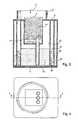
- FIG 1 Depicted in figure 1 is the device 1 for housing and simultaneously refilling with ink a colour cartridge 8 of a printhead, according to the invention, in which, indicated with the numeral 2, is a container made up of a bottom wall 4, a top wall 5, substantially parallel to the bottom wall 4, and at least one, external side wall 6, integrally linked with the other two walls 4 and 5.
- the bottom wall 4 is the support platform of the container 2 on a horizontal plane 10 on which to place the container itself in a vertical operating position, for refilling with ink the cartridge 8 ( fig. 2 ), as will be described in greater detail in the following.
- the container 2 may indiscriminately be made in a cylindrical shape, or as a parallelepiped, or a right-angled prism; in the first case, the side wall 6 will be made in a single, continuous piece, substantially shaped as a cylinder trunk; in the second case the side wall 6 will be made of various flat walls, four for instance, 6a, 6b, 6c and 6d, joined together and to the walls 4 and 5 ( fig. 3 ).
- top wall 5 Made in the top wall 5 is an aperture 11, shaped conveniently to allow passage of the cartridge 8, when it has to be inserted in a substantially parallelepiped shape seat 14, made inside the container 2, and connected integrally to the top wall 5; the housing 14 extends inside the container 2 in the direction of the bottom wall 4 and is closed at the bottom by a bottom wall 15, which isolates the housing 14 from the inner space of the container 2.
- a circular collar 16 Arranged around the aperture 11 is a circular collar 16 suitable for bearing a cover not depicted in the figures, with which to close the container 2 and maintain a sufficiently humid atmosphere inside it, thus preventing the ink from drying.
- the cartridge 8, in particular, according to a non-restrictive aspect of this invention, may be of the type in which a colour ink jet printhead 17 is integrated with the cartridge 8, as is shown by way of non-restrictive example in fig. 5 ; alternatively, the cartridge 8 may be without a printhead and in this case, may be inserted in an appropriate seat, on board a colour printer having its own printhead. Both the mentioned types of cartridge are well known to those acquainted with the sector art, and will not therefore be described in detail in this description.
- the colour cartridge 8 is divided internally into three R, G, B compartments ( fig. 2 ), each of which contains a spongy body 18, normally impregnated with the corresponding colour ink at the time of manufacture.
- R, G, B compartments of the cartridge 8 on completion of a printing cycle, has finished its original ink, it can be refilled repeatedly with the proper colour ink by means of the device 1, according to the invention.
- the cartridge 8, out of ink is inserted in the housing 14 where it may be refilled by means of a capillarity phenomenon, which simultaneously transfers the different colour inks to the cartridge 8, solely when the device 1 is disposed in an operating, or feeding, position, represented by the vertical position of the container 2, shown in figure 1 , wherein the latter is set with its support base 4 on the horizontal plane 10.
- the container 2 contains three tanks 20, 21, and 22 ( fig. 2 ), independent and separate from each other, each of which is suitable for containing corresponding, predetermined volumes of colour ink 24.
- the three colour inks contained in the corresponding tanks 20, 21, 22, will be designated as a whole with a single numeral 24.
- the three tanks 20, 21, 22 are substantially shaped as concentrical cylinders; more particularly, the outer tank 20 completely surrounds the intermediate tank 21, and both are disposed concentrically around the central tank 22, as represented in figure 3 .
- the ink 24 In the operating position, that is with the container 2 disposed in the vertical position, the ink 24 is contained in the bottom part of each of the tanks 20, 21 and 22, in corresponding feeding compartments 26, 27 and 28 ( fig. 1 ); in this position, each of the inks 24 occupies the corresponding feeding compartment 26, 27 and 28, to a pre-established level with respect to the support base 4, corresponding to a predetermined volume of colour ink, for example of approximately 200 ml and enough to completely refill, several times, the respective compartment of the cartridge 8.
- each of the tanks 20, 21 and 22 extends upwardly, i.e. in the direction of the top wall 5, forming corresponding back-flow compartments 30, 31 and 32 ( figs. 1 , 2 ); each of these back-flow compartments communicates freely with the corresponding feeding compartment below 26, 27 and 28.
- Each of the three tanks 20, 21 and 22 is sized such as to have a volume substantially not less than the predetermined volume of ink contained in the corresponding feeding compartments 26, 27 and 28.
- Feeding of the cartridge 8 is obtained thanks to refilling members, which comprise three capillary elements 34, 35 and 36, consisting of preformed cylinders of spongy material with communicating cells, inserted in corresponding cylindrical pipes 38, 39, and 40, of impermeable material.
- Each pipe is disposed vertically inside the container 2 and is attached at the top to the bottom wall 15 of the housing 14 and at the bottom to the bottom wall 41 of the innermost tank, the central tank 20 in figure 1 .
- the three pipes 38, 39 and 40 are grouped together one adjacent to the other, and disposed in the container 2 in a position ( fig. 3 ) that is central and symmetrical with respect to the profile of the bottom wall 4.
- the top end 42 of the pipes 38, 39 and 40 penetrates into the housing 14, whereas the bottom end 43 of the pipes protrudes respectively inside each feeding compartment 26, 27 and 28.
- the capillary elements 34,35 and 36 protrude at the top from their respective pipes to a prefixed height, to penetrate into the respective R, G, B compartments of the cartridge 8 in contact with the sponges inside ( fig. 2 ), so as to transfer each colour ink by capillarity from the respective tank to the corresponding compartment of the cartridge 8.
- the pipes extend beyond the bottom wall 41 of the central tank 22, to a short distance from the bottom wall 4 of the container 2, whereas the respective capillary elements are cut flush with the lower end 43 of the pipes; in particular, the pipe 40, belonging to the outer tank 20 and the pipe 38, belonging to the intermediate tank 21 ( fig. 1 ), respectively protrude into a first portion 44 and a second portion 45 of the tanks 20 and 21, said portions 44 and 45 extending partly and laterally below the bottom wall 41 of the central tank 22; the pipe 39 belonging to the central tank 22 protrudes inside a transverse channel 47 ( fig. 6 ) communicating with the central tank 22, and disposed on the bottom wall 4 of the container 2, said channel 47 separating the outer tank 20 from the intermediate tank 21.
- a transverse channel 47 fig. 6
- each of the capillary elements 34, 35, 36 is immersed in the corresponding colour ink contained in each of the feeding compartments 26, 27, 28, and can efficaciously refill, thanks to their capillarity, the three compartments of the cartridge 8.
- the inks flow into the respective back-flow compartments 30, 31, and 32, wherein they collect at a level that does not lap against the lower end 43 of the pipes, i.e. of the capillary elements 34, 35, and 36, so that feeding of the inks is automatically interrupted, thus excluding the risk of overfeeding any compartment of the cartridge 8, and accordingly encouraging ink to exit from the cartridge. In this way, even when the cartridge 8 is not in the housing 14, there is no danger of ink flowing out.
- the advantages obtained from the device according to the present invention will be evident, with respect to similar solutions known in the state of the art, in that the device 1 described, by ensuring the simultaneous feeding of three different colour inks to the cartridge 8, solely and exclusively when the container 2 is in the vertical operating position, avoids the inks being transferred through the capillary elements 34, 35, 36, when the container 2 is placed on its side, or turned upside down ( fig. 4 ).
- the capillary elements 34, 35, 36 remain separate from their respective inks, which flow into the back-flow compartments 30, 31, 32; in this position, the capillary elements 34, 35, 36 do not transfer the inks, avoiding any overfeeding of the cartridge 2, or spillage of ink inside the housing 14, in the absence of the cartridge 2.
- the pipes 38, 39 and 40 may be provided with longitudinal grooves 49, which enable air to pass between the tanks and the R, G, B compartments of the cartridge 2.
Landscapes
- Ink Jet (AREA)
- Vending Machines For Individual Products (AREA)
- Supplying Of Containers To The Packaging Station (AREA)
Claims (7)
- Vorrichtung zum Speichern und gleichzeitigen Wiederbefüllen einer Patrone (8) eines Farbdruckkopfes mit verschiedenen Farbtinten, aufweisend einen Behälter (2), in dem ein Gehäuse (14) für die wieder zu befüllende Patrone (8) und wenigstens drei unabhängige Tankbehälter (20, 21, 22) für verschiedene Farbtinten angeordnet sind, wobei jeder Tankbehälter mit einem Zufuhrelement (34, 35, 36) verbunden ist, das mit der Patrone (8) zusammenarbeitet, um die Tinte (24) jeder Farbe von dem entsprechenden Tankbehälter (20, 21, 22) zur Patrone (8) zu transferieren, wenn sich der Behälter (2) in der Arbeitsposition befindet, nämlich vertikal zu einer horizontalen Auflagefläche (10),
dadurch gekennzeichnet, dass
die Tankbehälter (20, 21, 22) in einer zentralen Position in dem Behälter (2) konzentrisch angeordnet sind, jeder der Tankbehälter (20, 21, 22) eine bestimmte Menge an Farbtinte, die sich in einem entsprechenden Zufuhrabteil (26, 27, 28) nahe einer Bodenwand (4) des Behälters (2) sammelt, aufnehmen kann, und jeder der Tankbehälter (20, 21, 22) sich in Richtung auf eine obere Wand (5) des Behälters (2) erstreckt, wodurch ein entsprechendes Rückflussabteil (30, 31, 32) gebildet wird, das mit dem entsprechenden Zufuhrabteil darunter (26, 27 und 28) frei in Verbindung steht, wobei die Rückflussabteile (30, 31, 32) die Farbtinten aufnehmen können, wenn der Behälter (2) seitlich gekippt oder kopfüber gedreht ist, so dass die Zufuhrelemente (34, 35, 36) aus den Tinten (24) auftauchen, wodurch die Zufuhr zur Patrone (8) unterbrochen wird. - Vorrichtung nach Anspruch 1,
dadurch gekennzeichnet, dass
die Tankbehälter (20, 21, 22) eine im Wesentlichen zylindrische Form haben, wobei ein äußerer Tankbehälter (20) und ein dazwischen liegender Tankbehälter (21) der drei Tankbehälter (20, 21, 22) ringförmig um einen zentralen Tankbehälter (22) angeordnet sind. - Vorrichtung nach Anspruch 1 oder 2,
dadurch gekennzeichnet, dass
die Rückflussabteile (30, 31, 32) eine im Wesentlichen zylindrische und konzentrische Form aufweisen und um das Gehäuse (14) der Patrone (8) angeordnet sind. - Vorrichtung nach einem der vorhergehenden Ansprüche,
dadurch gekennzeichnet, dass
die Zufuhrelemente drei Kapillarelemente (34, 35, 36) mit einer im Wesentlichen zylindrischen Form aufweisen, die in einer zentralen Position des Behälters (2) angeordnet sind und in entsprechende Rohre (38, 39, 40), die an dem Gehäuse (14) angebracht sind, eingeschoben sind, wobei jedes Rohr jeweils mit einem entsprechenden Rückflussabteil (26, 27, 28) verbunden ist, wobei die Kapillarelemente (34, 35, 36) mit der Patrone (8) zum Transferieren der Farbtinte (24) aus jedem der Zufuhrabteile (26, 27, 28) zu den Abteilen (R, G, B) der Patrone (8) ausschließlich nur dann zusammenarbeiten können, wenn sich der Behälter (2) in der vertikalen Arbeitsposition befindet. - Vorrichtung nach einem der Ansprüche 2 bis 4,
dadurch gekennzeichnet, dass
der äußere Tankbehälter (20) und der dazwischen liegende Tankbehälter (21) einen ersten und einen zweiten dazugehörigen Teil (44 und 45) aufweisen, die sich teilweise und seitlich unter einer Bodenwand (41) des zentralen Tankbehälters (22) erstrecken, und die unteren Enden (43) der beiden Kapillarelemente (34 und 36), die dem äußeren (20) und dem dazwischen liegenden (21) Tankbehälter zugeordnet sind, jeweils in den ersten und den zweiten Teil (44, 45) eintauchen, und das untere Ende (43) des Kapillarelements (37), das dem zentralen Tankbehälter (22) zugeordnet ist, in einem quer verlaufenden Kanal (47), der mit dem zentralen Tankbehälter (22) in Verbindung steht und an der Bodenwand (4) des Behälters (2) angeordnet ist, eintaucht, wobei der Kanal (47) den ersten seitlichen Teil (44) von dem zweiten seitlichen Teil (45) trennt. - Vorrichtung nach einem der vorhergehenden Ansprüche,
dadurch gekennzeichnet, dass
jedes der Rückflussabteile (30, 31, 32) ein Volumen hat, welches mindestens gleich dem Volumen der vorbestimmten Mengen an Farbtinte ist, die in den entsprechenden Zufuhrabteilen (26, 27 und 28) enthalten sind. - Vorrichtung nach einem der vorhergehenden Ansprüche,
dadurch gekennzeichnet, dass
die Rückflussabteile (30, 31, 32), die Zufuhrabteile (26, 27, 28) und die vorbestimmten Mengen an Farbtinte derart zueinander proportionale Volumina aufweisen, dass die Zufuhrelemente (34, 35, 36) nicht durch die Farbtinten bedeckt sind, wenn sich der Behälter (2) in irgendeiner anderen als der vertikalen Arbeitsposition befindet, so dass ein Austropfen und/oder Auslaufen der Tinte durch die Zufuhrelemente vermieden wird.
Applications Claiming Priority (2)
| Application Number | Priority Date | Filing Date | Title |
|---|---|---|---|
| IT000302A ITTO20030302A1 (it) | 2003-04-17 | 2003-04-17 | Dispositivo per custodire e rifornire contemporaneamente |
| PCT/IT2004/000183 WO2004091918A1 (en) | 2003-04-17 | 2004-04-07 | Device for storing and simultaeously refilling with different colour inks a cartridge of a colour printhead |
Publications (2)
| Publication Number | Publication Date |
|---|---|
| EP1615775A1 EP1615775A1 (de) | 2006-01-18 |
| EP1615775B1 true EP1615775B1 (de) | 2008-08-20 |
Family
ID=33187395
Family Applications (1)
| Application Number | Title | Priority Date | Filing Date |
|---|---|---|---|
| EP04726251A Expired - Lifetime EP1615775B1 (de) | 2003-04-17 | 2004-04-07 | Vorrichtung zum halten und nachfüllen einer tintenpatrone für einen farbendruckkopf |
Country Status (10)
| Country | Link |
|---|---|
| US (1) | US7273273B2 (de) |
| EP (1) | EP1615775B1 (de) |
| CN (1) | CN100404265C (de) |
| AT (1) | ATE405427T1 (de) |
| BR (1) | BRPI0409485B1 (de) |
| CA (1) | CA2522252A1 (de) |
| DE (1) | DE602004015964D1 (de) |
| ES (1) | ES2314390T3 (de) |
| IT (1) | ITTO20030302A1 (de) |
| WO (1) | WO2004091918A1 (de) |
Families Citing this family (6)
| Publication number | Priority date | Publication date | Assignee | Title |
|---|---|---|---|---|
| ITTO20030303A1 (it) * | 2003-04-17 | 2004-10-18 | Tecnost Sistemi S P A | Stazione di custodia e rifornimento di inchiostro di |
| JP4072967B2 (ja) * | 2005-03-30 | 2008-04-09 | 富士フイルム株式会社 | インクタンク及びインクジェット記録装置並びにインクタンクの製造方法 |
| EP2022637B8 (de) * | 2007-08-06 | 2012-03-21 | Pelikan Hardcopy Production AG | Vorrichtung zur Wiederbefüllung einer Tintenpatrone für einen Tintenstrahldrucker |
| DE202007019225U1 (de) * | 2007-08-06 | 2011-05-05 | Pelikan Hardcopy Production Ag | Vorrichtung zur Wiederbefüllung einer Tintenpatrone für einen Tintenstrahldrucker |
| JP6171313B2 (ja) * | 2011-12-08 | 2017-08-02 | セイコーエプソン株式会社 | 液体噴射装置 |
| WO2019151971A1 (en) * | 2018-01-30 | 2019-08-08 | Hewlett-Packard Development Company, L.P. | Printing system |
Family Cites Families (11)
| Publication number | Priority date | Publication date | Assignee | Title |
|---|---|---|---|---|
| GB492579A (en) | 1937-01-07 | 1938-09-22 | Rudolf Etzkorn | Improvements in or relating to a method and apparatus for mixing liquids |
| US4831389A (en) * | 1987-12-21 | 1989-05-16 | Hewlett-Packard Company | Off board ink supply system and process for operating an ink jet printer |
| IT1258135B (it) * | 1992-12-28 | 1996-02-20 | Olivetti Canon Ind Spa | Dispositivo per conservare e mantenere rifornite d'inchiostro le cartucce di una stampante a getto d'inchiostro. |
| JP3224180B2 (ja) * | 1994-08-31 | 2001-10-29 | キヤノン株式会社 | インク記録ヘッド用インクタンクのインク再充填方法および再充填装置 |
| CA2157346C (en) * | 1994-08-31 | 2001-08-28 | Osamu Sato | Ink jet ink refilling method and apparatus |
| EP0773109B1 (de) * | 1995-11-08 | 2002-10-02 | Canon Kabushiki Kaisha | Farbstoffnachfüllverfahren und -vorrichtung, Tintenbehälter und Tintenstrahlaufzeichnungsgerät mit einer solchen Vorrichtung |
| US6042224A (en) * | 1996-02-14 | 2000-03-28 | Fuji Xerox Co., Ltd. | Image recording device |
| US6270207B1 (en) * | 1998-03-30 | 2001-08-07 | Brother Kogyo Kabushiki Kaisha | Ink cartridge and remaining ink volume detection method |
| WO2000058100A1 (en) * | 1999-03-29 | 2000-10-05 | Seiko Epson Corporation | Method and device for filling ink into ink cartridge |
| US6880921B2 (en) * | 2002-09-12 | 2005-04-19 | Hewlett-Packard Development Company, L.P. | Inkjet cartridge with tubular entrained ink chamber |
| US6905198B2 (en) * | 2003-07-24 | 2005-06-14 | Hewlett-Packard Development Company, L.P. | Liquid supply vessel |
-
2003
- 2003-04-17 IT IT000302A patent/ITTO20030302A1/it unknown
-
2004
- 2004-04-07 ES ES04726251T patent/ES2314390T3/es not_active Expired - Lifetime
- 2004-04-07 US US10/553,709 patent/US7273273B2/en not_active Expired - Fee Related
- 2004-04-07 CA CA002522252A patent/CA2522252A1/en not_active Abandoned
- 2004-04-07 DE DE602004015964T patent/DE602004015964D1/de not_active Expired - Lifetime
- 2004-04-07 EP EP04726251A patent/EP1615775B1/de not_active Expired - Lifetime
- 2004-04-07 CN CNB2004800142098A patent/CN100404265C/zh not_active Expired - Fee Related
- 2004-04-07 BR BRPI0409485-9A patent/BRPI0409485B1/pt not_active IP Right Cessation
- 2004-04-07 AT AT04726251T patent/ATE405427T1/de not_active IP Right Cessation
- 2004-04-07 WO PCT/IT2004/000183 patent/WO2004091918A1/en not_active Ceased
Also Published As
| Publication number | Publication date |
|---|---|
| BRPI0409485B1 (pt) | 2014-08-05 |
| ES2314390T3 (es) | 2009-03-16 |
| DE602004015964D1 (de) | 2008-10-02 |
| US20060227186A1 (en) | 2006-10-12 |
| ITTO20030302A1 (it) | 2004-10-18 |
| CA2522252A1 (en) | 2004-10-28 |
| CN100404265C (zh) | 2008-07-23 |
| CN1795102A (zh) | 2006-06-28 |
| WO2004091918A1 (en) | 2004-10-28 |
| EP1615775A1 (de) | 2006-01-18 |
| US7273273B2 (en) | 2007-09-25 |
| ATE405427T1 (de) | 2008-09-15 |
| BRPI0409485A (pt) | 2006-05-09 |
Similar Documents
| Publication | Publication Date | Title |
|---|---|---|
| CN105774255B (zh) | 液体收纳容器和液体喷射系统 | |
| JP5644279B2 (ja) | 液体収容容器、及び、液体噴射システム | |
| EP0605183B1 (de) | Haltevorrichtung für Kassetten an einem Tintenstrahldrucker und Vorrichtung zum Aufrechterhalten des Tintenniveaus in den Kassetten | |
| CN101437685B (zh) | 储器和墨水笔组件 | |
| JP2001205820A (ja) | 2部分からなるふたを有するインクジェット・ペンおよび充填方法 | |
| EP1613478B1 (de) | Speicher und farbstoffnachfüllstation für eine druckkopfpatrone | |
| CN202192854U (zh) | 液体收纳容器、液体喷射系统以及液体供给系统 | |
| JP7622792B2 (ja) | キャップ及び液体容器 | |
| EP1615775B1 (de) | Vorrichtung zum halten und nachfüllen einer tintenpatrone für einen farbendruckkopf | |
| WO2010104500A2 (en) | Ink supply container | |
| JP7420195B2 (ja) | 印刷用液体容器 | |
| EP1447224A3 (de) | Automatische Farbzufuhreinrichtung für einen Drucker | |
| JP2022043079A5 (de) | ||
| JP2020189454A (ja) | 印刷用液体容器、システム、及びキャップ | |
| JP7352134B2 (ja) | システム | |
| EP3266615B1 (de) | Flüssigkeitsabgabevorrichtungen | |
| CN101374667A (zh) | 墨盒 | |
| US20050200668A1 (en) | Continually ink-supplying device for an inkjet printer | |
| US20060028514A1 (en) | Uninterrupted ink supply system for digital printers or "UISS" | |
| JP2005246899A (ja) | インクカートリッジ | |
| KR20160137789A (ko) | 프린터용 잉크공급용기 |
Legal Events
| Date | Code | Title | Description |
|---|---|---|---|
| PUAI | Public reference made under article 153(3) epc to a published international application that has entered the european phase |
Free format text: ORIGINAL CODE: 0009012 |
|
| 17P | Request for examination filed |
Effective date: 20051011 |
|
| AK | Designated contracting states |
Kind code of ref document: A1 Designated state(s): AT BE BG CH CY CZ DE DK EE ES FI FR GB GR HU IE IT LI LU MC NL PL PT RO SE SI SK TR |
|
| AX | Request for extension of the european patent |
Extension state: AL HR LT LV MK |
|
| DAX | Request for extension of the european patent (deleted) | ||
| GRAP | Despatch of communication of intention to grant a patent |
Free format text: ORIGINAL CODE: EPIDOSNIGR1 |
|
| GRAS | Grant fee paid |
Free format text: ORIGINAL CODE: EPIDOSNIGR3 |
|
| GRAA | (expected) grant |
Free format text: ORIGINAL CODE: 0009210 |
|
| AK | Designated contracting states |
Kind code of ref document: B1 Designated state(s): AT BE BG CH CY CZ DE DK EE ES FI FR GB GR HU IE IT LI LU MC NL PL PT RO SE SI SK TR |
|
| REG | Reference to a national code |
Ref country code: GB Ref legal event code: FG4D |
|
| REG | Reference to a national code |
Ref country code: CH Ref legal event code: EP |
|
| REG | Reference to a national code |
Ref country code: IE Ref legal event code: FG4D |
|
| REF | Corresponds to: |
Ref document number: 602004015964 Country of ref document: DE Date of ref document: 20081002 Kind code of ref document: P |
|
| PG25 | Lapsed in a contracting state [announced via postgrant information from national office to epo] |
Ref country code: NL Free format text: LAPSE BECAUSE OF FAILURE TO SUBMIT A TRANSLATION OF THE DESCRIPTION OR TO PAY THE FEE WITHIN THE PRESCRIBED TIME-LIMIT Effective date: 20080820 |
|
| PG25 | Lapsed in a contracting state [announced via postgrant information from national office to epo] |
Ref country code: FI Free format text: LAPSE BECAUSE OF FAILURE TO SUBMIT A TRANSLATION OF THE DESCRIPTION OR TO PAY THE FEE WITHIN THE PRESCRIBED TIME-LIMIT Effective date: 20080820 Ref country code: SI Free format text: LAPSE BECAUSE OF FAILURE TO SUBMIT A TRANSLATION OF THE DESCRIPTION OR TO PAY THE FEE WITHIN THE PRESCRIBED TIME-LIMIT Effective date: 20080820 Ref country code: AT Free format text: LAPSE BECAUSE OF FAILURE TO SUBMIT A TRANSLATION OF THE DESCRIPTION OR TO PAY THE FEE WITHIN THE PRESCRIBED TIME-LIMIT Effective date: 20080820 |
|
| REG | Reference to a national code |
Ref country code: ES Ref legal event code: FG2A Ref document number: 2314390 Country of ref document: ES Kind code of ref document: T3 |
|
| PG25 | Lapsed in a contracting state [announced via postgrant information from national office to epo] |
Ref country code: BE Free format text: LAPSE BECAUSE OF FAILURE TO SUBMIT A TRANSLATION OF THE DESCRIPTION OR TO PAY THE FEE WITHIN THE PRESCRIBED TIME-LIMIT Effective date: 20080820 |
|
| PG25 | Lapsed in a contracting state [announced via postgrant information from national office to epo] |
Ref country code: DK Free format text: LAPSE BECAUSE OF FAILURE TO SUBMIT A TRANSLATION OF THE DESCRIPTION OR TO PAY THE FEE WITHIN THE PRESCRIBED TIME-LIMIT Effective date: 20080820 Ref country code: BG Free format text: LAPSE BECAUSE OF FAILURE TO SUBMIT A TRANSLATION OF THE DESCRIPTION OR TO PAY THE FEE WITHIN THE PRESCRIBED TIME-LIMIT Effective date: 20081120 |
|
| PG25 | Lapsed in a contracting state [announced via postgrant information from national office to epo] |
Ref country code: SK Free format text: LAPSE BECAUSE OF FAILURE TO SUBMIT A TRANSLATION OF THE DESCRIPTION OR TO PAY THE FEE WITHIN THE PRESCRIBED TIME-LIMIT Effective date: 20080820 Ref country code: RO Free format text: LAPSE BECAUSE OF FAILURE TO SUBMIT A TRANSLATION OF THE DESCRIPTION OR TO PAY THE FEE WITHIN THE PRESCRIBED TIME-LIMIT Effective date: 20080820 Ref country code: PT Free format text: LAPSE BECAUSE OF FAILURE TO SUBMIT A TRANSLATION OF THE DESCRIPTION OR TO PAY THE FEE WITHIN THE PRESCRIBED TIME-LIMIT Effective date: 20090120 Ref country code: CZ Free format text: LAPSE BECAUSE OF FAILURE TO SUBMIT A TRANSLATION OF THE DESCRIPTION OR TO PAY THE FEE WITHIN THE PRESCRIBED TIME-LIMIT Effective date: 20080820 |
|
| PLBE | No opposition filed within time limit |
Free format text: ORIGINAL CODE: 0009261 |
|
| STAA | Information on the status of an ep patent application or granted ep patent |
Free format text: STATUS: NO OPPOSITION FILED WITHIN TIME LIMIT |
|
| 26N | No opposition filed |
Effective date: 20090525 |
|
| PG25 | Lapsed in a contracting state [announced via postgrant information from national office to epo] |
Ref country code: EE Free format text: LAPSE BECAUSE OF FAILURE TO SUBMIT A TRANSLATION OF THE DESCRIPTION OR TO PAY THE FEE WITHIN THE PRESCRIBED TIME-LIMIT Effective date: 20080820 |
|
| REG | Reference to a national code |
Ref country code: CH Ref legal event code: PL |
|
| PG25 | Lapsed in a contracting state [announced via postgrant information from national office to epo] |
Ref country code: CH Free format text: LAPSE BECAUSE OF NON-PAYMENT OF DUE FEES Effective date: 20090430 Ref country code: SE Free format text: LAPSE BECAUSE OF FAILURE TO SUBMIT A TRANSLATION OF THE DESCRIPTION OR TO PAY THE FEE WITHIN THE PRESCRIBED TIME-LIMIT Effective date: 20081120 Ref country code: LI Free format text: LAPSE BECAUSE OF NON-PAYMENT OF DUE FEES Effective date: 20090430 |
|
| PG25 | Lapsed in a contracting state [announced via postgrant information from national office to epo] |
Ref country code: IE Free format text: LAPSE BECAUSE OF NON-PAYMENT OF DUE FEES Effective date: 20090407 Ref country code: MC Free format text: LAPSE BECAUSE OF NON-PAYMENT OF DUE FEES Effective date: 20090430 |
|
| PG25 | Lapsed in a contracting state [announced via postgrant information from national office to epo] |
Ref country code: PL Free format text: LAPSE BECAUSE OF FAILURE TO SUBMIT A TRANSLATION OF THE DESCRIPTION OR TO PAY THE FEE WITHIN THE PRESCRIBED TIME-LIMIT Effective date: 20080820 |
|
| PG25 | Lapsed in a contracting state [announced via postgrant information from national office to epo] |
Ref country code: GR Free format text: LAPSE BECAUSE OF FAILURE TO SUBMIT A TRANSLATION OF THE DESCRIPTION OR TO PAY THE FEE WITHIN THE PRESCRIBED TIME-LIMIT Effective date: 20081121 |
|
| PG25 | Lapsed in a contracting state [announced via postgrant information from national office to epo] |
Ref country code: LU Free format text: LAPSE BECAUSE OF NON-PAYMENT OF DUE FEES Effective date: 20090407 |
|
| PG25 | Lapsed in a contracting state [announced via postgrant information from national office to epo] |
Ref country code: HU Free format text: LAPSE BECAUSE OF FAILURE TO SUBMIT A TRANSLATION OF THE DESCRIPTION OR TO PAY THE FEE WITHIN THE PRESCRIBED TIME-LIMIT Effective date: 20090221 |
|
| PG25 | Lapsed in a contracting state [announced via postgrant information from national office to epo] |
Ref country code: TR Free format text: LAPSE BECAUSE OF FAILURE TO SUBMIT A TRANSLATION OF THE DESCRIPTION OR TO PAY THE FEE WITHIN THE PRESCRIBED TIME-LIMIT Effective date: 20080820 |
|
| PG25 | Lapsed in a contracting state [announced via postgrant information from national office to epo] |
Ref country code: CY Free format text: LAPSE BECAUSE OF FAILURE TO SUBMIT A TRANSLATION OF THE DESCRIPTION OR TO PAY THE FEE WITHIN THE PRESCRIBED TIME-LIMIT Effective date: 20080820 |
|
| REG | Reference to a national code |
Ref country code: FR Ref legal event code: PLFP Year of fee payment: 12 |
|
| REG | Reference to a national code |
Ref country code: DE Ref legal event code: R082 Ref document number: 602004015964 Country of ref document: DE Representative=s name: PATENTANWAELTE WEICKMANN & WEICKMANN, DE Ref country code: DE Ref legal event code: R082 Ref document number: 602004015964 Country of ref document: DE Representative=s name: WEICKMANN & WEICKMANN PATENTANWAELTE - RECHTSA, DE |
|
| PGFP | Annual fee paid to national office [announced via postgrant information from national office to epo] |
Ref country code: DE Payment date: 20150429 Year of fee payment: 12 Ref country code: ES Payment date: 20150427 Year of fee payment: 12 Ref country code: GB Payment date: 20150427 Year of fee payment: 12 |
|
| PGFP | Annual fee paid to national office [announced via postgrant information from national office to epo] |
Ref country code: IT Payment date: 20150427 Year of fee payment: 12 Ref country code: FR Payment date: 20150417 Year of fee payment: 12 |
|
| REG | Reference to a national code |
Ref country code: DE Ref legal event code: R119 Ref document number: 602004015964 Country of ref document: DE |
|
| GBPC | Gb: european patent ceased through non-payment of renewal fee |
Effective date: 20160407 |
|
| REG | Reference to a national code |
Ref country code: FR Ref legal event code: ST Effective date: 20161230 |
|
| PG25 | Lapsed in a contracting state [announced via postgrant information from national office to epo] |
Ref country code: GB Free format text: LAPSE BECAUSE OF NON-PAYMENT OF DUE FEES Effective date: 20160407 Ref country code: DE Free format text: LAPSE BECAUSE OF NON-PAYMENT OF DUE FEES Effective date: 20161101 Ref country code: FR Free format text: LAPSE BECAUSE OF NON-PAYMENT OF DUE FEES Effective date: 20160502 |
|
| PG25 | Lapsed in a contracting state [announced via postgrant information from national office to epo] |
Ref country code: IT Free format text: LAPSE BECAUSE OF NON-PAYMENT OF DUE FEES Effective date: 20160407 |
|
| PG25 | Lapsed in a contracting state [announced via postgrant information from national office to epo] |
Ref country code: ES Free format text: LAPSE BECAUSE OF NON-PAYMENT OF DUE FEES Effective date: 20160408 |
|
| REG | Reference to a national code |
Ref country code: ES Ref legal event code: FD2A Effective date: 20181204 |