EP1613887B1 - Plastic tube joint - Google Patents
Plastic tube joint Download PDFInfo
- Publication number
- EP1613887B1 EP1613887B1 EP04759321A EP04759321A EP1613887B1 EP 1613887 B1 EP1613887 B1 EP 1613887B1 EP 04759321 A EP04759321 A EP 04759321A EP 04759321 A EP04759321 A EP 04759321A EP 1613887 B1 EP1613887 B1 EP 1613887B1
- Authority
- EP
- European Patent Office
- Prior art keywords
- tubing
- ferrule
- collet
- connector body
- section
- Prior art date
- Legal status (The legal status is an assumption and is not a legal conclusion. Google has not performed a legal analysis and makes no representation as to the accuracy of the status listed.)
- Expired - Lifetime
Links
- 229920003023 plastic Polymers 0.000 title abstract description 31
- 239000004033 plastic Substances 0.000 title abstract description 31
- 239000011800 void material Substances 0.000 claims abstract description 7
- 238000000034 method Methods 0.000 abstract description 7
- 229920000642 polymer Polymers 0.000 description 7
- 229920003020 cross-linked polyethylene Polymers 0.000 description 6
- 239000004703 cross-linked polyethylene Substances 0.000 description 6
- 239000000463 material Substances 0.000 description 5
- 238000005304 joining Methods 0.000 description 4
- 239000002184 metal Substances 0.000 description 4
- 229910052751 metal Inorganic materials 0.000 description 4
- 238000007789 sealing Methods 0.000 description 4
- 238000003466 welding Methods 0.000 description 4
- 238000009434 installation Methods 0.000 description 3
- 238000004519 manufacturing process Methods 0.000 description 3
- 238000002844 melting Methods 0.000 description 3
- 230000008018 melting Effects 0.000 description 3
- -1 polyethylene Polymers 0.000 description 3
- 239000002516 radical scavenger Substances 0.000 description 3
- 229920013744 specialty plastic Polymers 0.000 description 3
- 239000000126 substance Substances 0.000 description 3
- 229910001369 Brass Inorganic materials 0.000 description 2
- RYGMFSIKBFXOCR-UHFFFAOYSA-N Copper Chemical compound [Cu] RYGMFSIKBFXOCR-UHFFFAOYSA-N 0.000 description 2
- 239000002033 PVDF binder Substances 0.000 description 2
- 239000004698 Polyethylene Substances 0.000 description 2
- 239000004721 Polyphenylene oxide Substances 0.000 description 2
- 230000000712 assembly Effects 0.000 description 2
- 238000000429 assembly Methods 0.000 description 2
- 239000010951 brass Substances 0.000 description 2
- 230000006835 compression Effects 0.000 description 2
- 238000007906 compression Methods 0.000 description 2
- 238000001816 cooling Methods 0.000 description 2
- 229910052802 copper Inorganic materials 0.000 description 2
- 239000010949 copper Substances 0.000 description 2
- 238000010168 coupling process Methods 0.000 description 2
- 238000005859 coupling reaction Methods 0.000 description 2
- 238000002788 crimping Methods 0.000 description 2
- 238000010438 heat treatment Methods 0.000 description 2
- 229920000573 polyethylene Polymers 0.000 description 2
- 229920006380 polyphenylene oxide Polymers 0.000 description 2
- 229920002981 polyvinylidene fluoride Polymers 0.000 description 2
- 239000004677 Nylon Substances 0.000 description 1
- 239000004743 Polypropylene Substances 0.000 description 1
- 229910000831 Steel Inorganic materials 0.000 description 1
- 229920006362 Teflon® Polymers 0.000 description 1
- 230000003213 activating effect Effects 0.000 description 1
- 238000004026 adhesive bonding Methods 0.000 description 1
- 230000008878 coupling Effects 0.000 description 1
- 230000009977 dual effect Effects 0.000 description 1
- 230000000694 effects Effects 0.000 description 1
- 230000008030 elimination Effects 0.000 description 1
- 238000003379 elimination reaction Methods 0.000 description 1
- 230000001747 exhibiting effect Effects 0.000 description 1
- 238000001914 filtration Methods 0.000 description 1
- 239000012530 fluid Substances 0.000 description 1
- 238000001746 injection moulding Methods 0.000 description 1
- 229920001778 nylon Polymers 0.000 description 1
- 238000009428 plumbing Methods 0.000 description 1
- 229920001155 polypropylene Polymers 0.000 description 1
- 239000010959 steel Substances 0.000 description 1
- 239000012815 thermoplastic material Substances 0.000 description 1
- XLYOFNOQVPJJNP-UHFFFAOYSA-N water Substances O XLYOFNOQVPJJNP-UHFFFAOYSA-N 0.000 description 1
Images


Classifications
-
- F—MECHANICAL ENGINEERING; LIGHTING; HEATING; WEAPONS; BLASTING
- F16—ENGINEERING ELEMENTS AND UNITS; GENERAL MEASURES FOR PRODUCING AND MAINTAINING EFFECTIVE FUNCTIONING OF MACHINES OR INSTALLATIONS; THERMAL INSULATION IN GENERAL
- F16L—PIPES; JOINTS OR FITTINGS FOR PIPES; SUPPORTS FOR PIPES, CABLES OR PROTECTIVE TUBING; MEANS FOR THERMAL INSULATION IN GENERAL
- F16L47/00—Connecting arrangements or other fittings specially adapted to be made of plastics or to be used with pipes made of plastics
- F16L47/02—Welded joints; Adhesive joints
-
- F—MECHANICAL ENGINEERING; LIGHTING; HEATING; WEAPONS; BLASTING
- F16—ENGINEERING ELEMENTS AND UNITS; GENERAL MEASURES FOR PRODUCING AND MAINTAINING EFFECTIVE FUNCTIONING OF MACHINES OR INSTALLATIONS; THERMAL INSULATION IN GENERAL
- F16L—PIPES; JOINTS OR FITTINGS FOR PIPES; SUPPORTS FOR PIPES, CABLES OR PROTECTIVE TUBING; MEANS FOR THERMAL INSULATION IN GENERAL
- F16L13/00—Non-disconnectable pipe joints, e.g. soldered, adhesive, or caulked joints
- F16L13/02—Welded joints
- F16L13/0209—Male-female welded joints
-
- F—MECHANICAL ENGINEERING; LIGHTING; HEATING; WEAPONS; BLASTING
- F16—ENGINEERING ELEMENTS AND UNITS; GENERAL MEASURES FOR PRODUCING AND MAINTAINING EFFECTIVE FUNCTIONING OF MACHINES OR INSTALLATIONS; THERMAL INSULATION IN GENERAL
- F16L—PIPES; JOINTS OR FITTINGS FOR PIPES; SUPPORTS FOR PIPES, CABLES OR PROTECTIVE TUBING; MEANS FOR THERMAL INSULATION IN GENERAL
- F16L39/00—Joints or fittings for double-walled or multi-channel pipes or pipe assemblies
-
- F—MECHANICAL ENGINEERING; LIGHTING; HEATING; WEAPONS; BLASTING
- F16—ENGINEERING ELEMENTS AND UNITS; GENERAL MEASURES FOR PRODUCING AND MAINTAINING EFFECTIVE FUNCTIONING OF MACHINES OR INSTALLATIONS; THERMAL INSULATION IN GENERAL
- F16L—PIPES; JOINTS OR FITTINGS FOR PIPES; SUPPORTS FOR PIPES, CABLES OR PROTECTIVE TUBING; MEANS FOR THERMAL INSULATION IN GENERAL
- F16L47/00—Connecting arrangements or other fittings specially adapted to be made of plastics or to be used with pipes made of plastics
Definitions
- the present invention relates generally to the field of forming joints for plastic tubing. More specifically, the present invention relates to a method of forming a permanent, leak-proof joint with plastic tubing, particularly plastic tubing made of high performance polymers.
- plastic tubing Since its invention, plastic tubing has increasingly been used in residential, commercial and industrial applications that were previously the domain of brass, copper and steel tubing. Plastic tubing offers many advantages over its metal predecessors. Plastic tubing is extremely flexible allowing for quick and easy installation as compared to metal tubing. In the case of demanding applications, the wide variety of available plastic polymers allows a user to select chemically inert and resistant tubing to meet the unique requirements of their application. Finally, nearly anyone can install plastic tubing as it does not require the skill set that typical metal tubing installations require.
- PEX tubing An example of the types of problems associated with creating permanent, leak-proof joints is demonstrated by PEX tubing.
- the fundamental result is that the molecular chains of polyethylene are cross-linked resulting in a polymer that shows strength and durability over a wide temperature range.
- This strength and durability prevents PREX from exhibiting the chemical and adhesive bonding traits that are common with other polymers.
- a variety of mechanical means for creating joints with PEX tubing have been developed. These means typically include crimping means and metal tubing inserts.
- Such mechanical means include the Vanguard CRIMPSERT TM metallic insert fitting.
- the CRIMPSERT TM fitting uses insert fittings and crimp rings made of copper or brass. Using a crimping tool, the user is able to mechanically seal the joint
- Another example of such mechanical sealing means includes the Wirsbo ProPEX® fitting system.
- the ProPEX® system uses the shaped-memory characteristic of PEX.
- An expander tool is used to expand an end of the PEX tubing.
- An insert fitting is inserted into this expanded tubing and the expander tool is then removed.
- the tubing returns to its original shape thereby compressing and holding the insert fitting in place.
- US 3,753,575 discloses a fluid-coupling assembly including a pair of rigid housings clamped together including parallel bores therethrough into which flexible hoses project, a rigid barbed ferrule disposed within the inner end of each hose, each ferrule having a fluid seal with one of the housings.
- a connector assembly comprising:
- the preferred embodiment includes a fitting component to be used in connecting and sealing plastic tubing with non-tubing assemblies.
- the invention preferably makes use of ultrasonic welding, either spin welding or shear welding, but most preferably, shear welding.
- the components of the preferred embodiment are formed by injection molding thermoplastic material. Satisfactory results have been achieved using ABS for the collet and connector body and PPO (polyphenylene oxide) for the ferrule. Such a device allows for high volume use of the invention while at the same time maintaining a high degree or repeatability. Examples of assemblies in which the embodiment could be practiced include water filtration equipment, appliances and plumbing connections.
- the present invention is a connector assembly having the features indication in claim 1.
- the connector assembly of the present invention is shown generally at 10 in the figures.
- the connector assembly 10 is used for permanently connecting a plastic tube 100 to another device.
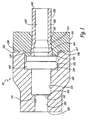
- a first embodiment of the connector assembly 10 is comprised of ferrule 110, collet 115, and connector body 120, as depicted in Fig. 1 .
- Plastic tubing 100 is defined by proximal end 130 and distal end 140. Plastic tubing 100 comprises tube wall 150 and a hollow lumen 160. The plastic tubing 100 is preferably formed of a pliable, resilient plastic material.
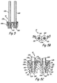
- the ferrule 110 is preferably made of a plastic material, a noted above. Referring to Figs. 2-2c , the ferrule 100 has a central bore 111 defined concentric with the longitudinal axis thereof.
- the ferrule 110 has a tubing end 112 and an opposed connector end 113.
- the external margin of the ferrule 110 has a flared section 114 extending inward from the tubing end 112 to a first cylindrical section 116.
- the first cylindrical section 116 is connected by a step to a second cylindrical section 117.
- the second cylindrical section 117 has a reduced diameter as compared to the diameter of the first cylindrical section 116.
- the second cylindrical section 117 is connected to a flange 118, having a diameter that is significantly greater than both of the cylindrical sections 116, 117.
- a very slightly tapered section 119 extends from the flange 118 to the connector end 113 of the ferrule 110.
- a seal 140 may be placed on the tapered section 119 and abutted to the flange 118, as depicted in Fig. 1 .
- the seal 140 may be an elastomeric O-ring.
- the collet 115 is also preferably formed of a plastic material as noted above and is generally ring shaped. More specifically, the collet 115 has an axial bore 121 defined therethrough. The bore 121 has a flared entrance 122. The flared entrance 122 is coupled to a short, generally cylindrical first section 123. The first section terminates in a shallow step 124. The step 124 is connected to a second section 125 that is also generally cylindrical and has a slightly greater diameter than the first section 123.
- the collet end margin 127 is generally planar, but has a circular energy director 126 formed thereon that may be triangular in cross section, having an elevated peak.
- Fig. 1 depicts the connector body 120.
- the connector body 120 is preferably made of a plastic material as noted above and may be formed integral to a device to which it is desired to connect the tube 100, such as, for example, the manifold of a filter assembly.
- the connector body 120 may as well be operably coupled to such device by bonding thereto or otherwise connecting thereto.
- the connector body 120 has a central longitudinal bore 130.
- the bore 130 has a generally cylindrical section 131 coupled to the distal end 129 of the connector body 120. Bore section 131 terminates at step 132 connected to generally cylindrical section 133.
- Section 133 has a greater diameter than section 131. Bore section 133 terminates at step 134 connected to generally cylindrical section 135.
- Section 135 has a greater diameter than section 133.
- Section 135 flares outward at flared section 136 to proximal end 138 of the connector body 120.
- the proximal end 138 is generally planar and may have a textured surface to promote the bonding thereof.
- the ferrule 110 with the seal 140 in place is inserted into the bore 130 of the connector body 120.
- the seal is preferably radially compressed between the exterior margin of the ferrule and the bore section 135 of the bore 130.
- the flange 118 does not necessarily, but may sealingly compress the seal 140 between the flange 118 and the step 134 and bore section 135 of the connector body 120.
- the proximal end 130 of the tubing 100 is slid over the taper 114.
- the taper 114 expands the tubing 100 radially outward.
- the tubing 100 is forced leftward, as depicted in Fig. 1 , until the proximal end 130 abuts the side margin of the flange 118.
- the resilient tubing 100 contracts to its original shape after passing over the taper 114 into contact with the second cylindrical section 117.
- a leftward directed biasing force is applied to both the plastic tubing 100 and the collet 115.
- the collet 115 is forced leftward by a compression device, comprising a piston or similar force applicator.
- the energy director 126 is forced into contact with the preferably textured proximal end 138 of the connector body 120.
- the shallow step 124 compressively engages the tubing 100 and forms a narrow neck in cooperation with the surface 116 of the ferrule 110, thereby capturing the portion of the tubing 100 that has contracted around the cylindrical surface 117.
- the user While maintaining intimate contact between the collet 115 and the connector body 120, the user activates an ultrasonic generator (not shown). Activating the ultrasonic generator causes the interface between the collet 115 and the connector body 120 at surfaces 127, 138 to be heated. Heating is enhanced by the energy director 126 being forced into contact with the preferably textured proximal end 138 of the connector body 120. The heating efficiently softens and deforms the energy director 126 and promotes efficient bonding with the preferably textured proximal end 138.
- the heat in cooperation with the leftward directed force on the tubing 100 further causes the proximal end of the tubing 100 to soften and to further fill the void defined adjacent to the flare 114 by the cylindrical surface 117 and the flange 118 of the ferrule 110, and the cylindrical surface 125 of the collet 115.
- the application of heat by the ultrasonic energy causes melting proximate surfaces 127, 138 and subsequent cooling substantially permanently bonds the collet 115 to the connector body 120 and substantially permanently and mechanically captures the tubing 110 between the collet 115 and the ferrule 110.
- the tubing 100 may not be withdrawn with any reasonable force application. This is a mechanical tube connection with no chemical connection between the tube 100 and ferrule 110, collet 115, and/or connector body 120.
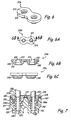
- Figs. 5 and 6 depict a further embodiment of the present invention useful for simultaneously joining two tubes 100 to a connector body 120a.
- the collet 115a and the connector body 120a are formed with dual receptacles for a pair of tubes 100.
- the two ferrules 110 are formed identical to the ferrules 110 noted above.
- the various features of the collet 115a and the connector body 120a are as noted above with respect to the single tube 100 embodiment. Operation to effect the joining of the pair of tubes 100 to the connector body 120a is the same as noted above with respect to joining a single tube 100 to the connector body 120.
- the advantage of this embodiment is the elimination of a joining procedure where two tubes 100 are used in close proximity.
- FIG. 7-12 A further embodiment of the present invention is depicted in Figs. 7-12 .
- the connector assembly 10 of Figs. 7-11 includes numerals identifying a common assembly component that are the same as the numerals noted above.
- ferrule 110 depicted in Figs. 7 , 10 and 11 , is virtually identical to the ferrule 110 described above.
- the collet 115b differs in certain respect from the collets 115 and 115a noted above.
- the collet 115b has a generally planar end margin 127.
- the end margin 127 has a relatively rough surface.
- a circular scavenger groove 128 is defined in the end margin 127.
- the bore 121 of collet 115b includes an indent 126.
- the indent 126 is generally opposite the flared section 114 and adjacent cylindrical section 116 of the ferrule 110.
- the space between the indent 126 and the flared section 114 and first cylindrical section 116 defines a generally expanded path through which the plastic tube 100 must pass, the path contracted downstream of the expansion.
- the collet 115b has a pair of hexagonal margins 140 that define a portion of the exterior margin of the collet 115b.
- a respective hexagonal margin 140 is concentric with a respective bore 121 defined in the collet 115b.
- the connector body 120 depicted in Fig. 7 includes a hexagonal bore portion 136a that forms an end portion of the bore 130.
- the tube connection is effected as noted above.
- a force is exerted upon the collet 115b at the same time that sonic energy is applied.
- the roughness of the surfaces 127, 138 promotes melting at the interface of the surfaces 127, 138.
- This melting in conjunction with the force exerted on the collet 115b causes the collet to move closer to the connector body 120 about .050 inches.
- Melt that is generated at the interface of the surfaces 127, 138 then flows into the scavenger groove 128.
- Subsequent cooling causes bonding between the collet 115b and the connector body at the interface of the surfaces 127, 138 and by means of the melted material exposed within the scavenger groove 128. In this manner, the plastic tube 100 is mechanically captured between the ferrule 110 and collet 115b.
Landscapes
- Engineering & Computer Science (AREA)
- General Engineering & Computer Science (AREA)
- Mechanical Engineering (AREA)
- Lining Or Joining Of Plastics Or The Like (AREA)
- Quick-Acting Or Multi-Walled Pipe Joints (AREA)
- Joints That Cut Off Fluids, And Hose Joints (AREA)
- Shaping Of Tube Ends By Bending Or Straightening (AREA)
Applications Claiming Priority (2)
| Application Number | Priority Date | Filing Date | Title |
|---|---|---|---|
| US10/412,050 US7156423B2 (en) | 2003-04-11 | 2003-04-11 | Plastic tube joint |
| PCT/US2004/010923 WO2004092631A2 (en) | 2003-04-11 | 2004-04-09 | Plastic tube joint |
Publications (3)
| Publication Number | Publication Date |
|---|---|
| EP1613887A2 EP1613887A2 (en) | 2006-01-11 |
| EP1613887A4 EP1613887A4 (en) | 2007-11-14 |
| EP1613887B1 true EP1613887B1 (en) | 2011-06-08 |
Family
ID=33131138
Family Applications (1)
| Application Number | Title | Priority Date | Filing Date |
|---|---|---|---|
| EP04759321A Expired - Lifetime EP1613887B1 (en) | 2003-04-11 | 2004-04-09 | Plastic tube joint |
Country Status (8)
| Country | Link |
|---|---|
| US (1) | US7156423B2 (enExample) |
| EP (1) | EP1613887B1 (enExample) |
| JP (1) | JP4624345B2 (enExample) |
| CN (1) | CN1774595B (enExample) |
| AU (1) | AU2004230594A1 (enExample) |
| BR (1) | BRPI0409756A (enExample) |
| MX (1) | MXPA05010877A (enExample) |
| WO (1) | WO2004092631A2 (enExample) |
Families Citing this family (18)
| Publication number | Priority date | Publication date | Assignee | Title |
|---|---|---|---|---|
| DE10051606A1 (de) * | 2000-10-18 | 2002-05-02 | Loi Thermprocess Gmbh | Verfahren und Vorrichtung zum Glühen von Rohren |
| US20050173323A1 (en) * | 2003-10-28 | 2005-08-11 | Meuleners William J. | Designs for filtration systems within appliances |
| JP4790633B2 (ja) | 2004-01-20 | 2011-10-12 | スリーエム イノベーティブ プロパティーズ カンパニー | 冷蔵庫用の、水フィルタ付き水ディスペンサー |
| NL1029030C2 (nl) * | 2005-05-12 | 2006-11-14 | Actuant Corp | Hydraulisch systeem. |
| DE102005055046A1 (de) * | 2005-11-16 | 2007-05-24 | J. Eberspächer GmbH & Co. KG | Übersprecher für eine Abgasanlage |
| US20070236010A1 (en) * | 2006-04-06 | 2007-10-11 | Campau Daniel N | Connector for corrugated conduit |
| JP5351386B2 (ja) * | 2006-05-17 | 2013-11-27 | カルソニックカンセイ株式会社 | 熱交換器の配管コネクタ |
| USD642244S1 (en) * | 2006-07-26 | 2011-07-26 | Colder Products Company | Fluid coupling |
| DE102008059087A1 (de) * | 2008-11-26 | 2010-05-27 | Veritas Ag | Leitungsanordnung für ein unter Druck stehendes Fluid und Verfahren zu deren Herstellung |
| USD638104S1 (en) | 2009-05-29 | 2011-05-17 | Govoni Arthur S | Coupler for plumbing fixtures |
| USD632372S1 (en) | 2009-05-29 | 2011-02-08 | Govoni Arthur S | Coupler for plumbing fixtures |
| USD617429S1 (en) | 2009-05-29 | 2010-06-08 | Govoni Arthur S | Coupler for plumbing fixtures |
| WO2011132519A1 (ja) * | 2010-04-22 | 2011-10-27 | 日本ピラー工業株式会社 | 溶着継手及びその溶着方法、溶着装置、溶着継手、樹脂管溶着装置及び溶着方法 |
| US8328448B1 (en) * | 2010-06-09 | 2012-12-11 | Hufnagel Randall S | Hardware hole filling device |
| CN103091504A (zh) * | 2011-10-31 | 2013-05-08 | 深圳迈瑞生物医疗电子股份有限公司 | 管路转接器组件、试剂容器组件及样本分析仪 |
| CN110206944A (zh) * | 2019-07-08 | 2019-09-06 | 袁德强 | 一种新型焊接式快速接头结构 |
| US11585465B2 (en) | 2020-09-03 | 2023-02-21 | Evergreen Innovation Group, LLC | Modular conduit systems with alignment members |
| TWM623783U (zh) * | 2021-11-12 | 2022-02-21 | 志合訊息股份有限公司 | 給水裝置及其水管接頭結構 |
Family Cites Families (87)
| Publication number | Priority date | Publication date | Assignee | Title |
|---|---|---|---|---|
| US2701147A (en) * | 1949-02-26 | 1955-02-01 | Aeromat Products Company Inc | Quick-release conduit connection |
| US3312483A (en) | 1960-08-17 | 1967-04-04 | D And G Plastics Co | Pipe connector |
| US3312484A (en) | 1960-10-31 | 1967-04-04 | D & G Plastics Co | Toggle ring tube coupling |
| US3583710A (en) | 1968-09-20 | 1971-06-08 | Plastic Omnium Sa | Joint for plastic tubes |
| US3695643A (en) | 1970-05-18 | 1972-10-03 | Hancock Brick & Tile Co | Corrugated tube coupling means |
| US3669475A (en) | 1970-05-22 | 1972-06-13 | Mueller Co | Compression couplings |
| US3753575A (en) * | 1971-10-20 | 1973-08-21 | Cornelius Co | Fluid coupling assembly |
| US3874709A (en) | 1972-09-18 | 1975-04-01 | Cardinal Of Adrian | Tubing fitting |
| FR2271490B1 (enExample) * | 1973-08-21 | 1976-09-17 | Legris France Sa | |
| CH553942A (de) | 1973-01-31 | 1974-09-13 | Legris France Sa | Schnellanschluss fuer eine schlauch- oder rohrleitung. |
| US3999783A (en) | 1973-04-24 | 1976-12-28 | Ste. Legris France S.A. | Connector for fluid conduits, such as semi-rigid pipe |
| FR2227483B1 (enExample) | 1973-04-24 | 1975-08-22 | Legris France Sa | |
| SE428596B (sv) | 1975-04-09 | 1983-07-11 | Raychem Corp | Anordning for hopkoppling av substrat exv ror omfattande ett organ av minnesmetall |
| US3873132A (en) * | 1974-02-19 | 1975-03-25 | American Flange & Mfg | Plastic container closure flange |
| US3893716A (en) | 1974-04-01 | 1975-07-08 | Weatherhead Co | Flareless fitting |
| GB1520742A (en) | 1975-07-30 | 1978-08-09 | Guest J D | Couplings for tubes |
| US3929359A (en) | 1974-11-04 | 1975-12-30 | Hancock Brick & Tile Co | Connecting joint structure for corrugated plastic tubing |
| US4022499A (en) | 1975-04-14 | 1977-05-10 | Aeroquip Corporation | Tube retaining compression fitting |
| US4037864A (en) | 1975-04-14 | 1977-07-26 | Emco Ltd. | Pipe coupling |
| US3994515A (en) | 1975-11-21 | 1976-11-30 | Cotten Roger C | Joinder of plastic pipe |
| US4146254A (en) | 1976-03-31 | 1979-03-27 | Bristol Products, Inc. | Coupler for tubing |
| US4072328A (en) | 1976-05-25 | 1978-02-07 | Hepworth Plastics Limited | Pipe couplings |
| US4049034A (en) * | 1976-07-14 | 1977-09-20 | Baxter Travenol Laboratories, Inc. | Attaching means and method for attaching flexible tubing to a plastic container |
| US4123090A (en) | 1976-07-19 | 1978-10-31 | Imperial-Eastman Corporation | Push-pull fitting |
| US4178023A (en) | 1977-02-09 | 1979-12-11 | Guest John D | Couplings for tubes |
| JPS5730545Y2 (enExample) | 1978-04-29 | 1982-07-05 | ||
| US4220361A (en) | 1979-02-01 | 1980-09-02 | The Aro Corporation | Connector for plastic tubing |
| US4586734A (en) | 1982-12-08 | 1986-05-06 | General Industries, Inc. | Pipe joint assembly |
| GB2132295B (en) | 1982-12-13 | 1986-03-19 | Guest John Ltd | Pipe coupling |
| JPS59180190A (ja) * | 1983-03-26 | 1984-10-13 | 東海ゴム工業株式会社 | ホ−ス継手 |
| GB2143603B (en) | 1983-07-21 | 1986-07-09 | Guest John Ltd | Quick release tube coupling |
| US4722560A (en) | 1983-07-21 | 1988-02-02 | Guest John D | Quick release tube coupling |
| FR2581155B1 (fr) | 1985-04-29 | 1987-10-16 | Legris Sa | Dispositif de raccordement instantane pour tubes en matiere plastique et metalliques. |
| US4635975A (en) | 1985-09-25 | 1987-01-13 | Jaco Manufacturing Company | Quick-connect tube coupling |
| GB8526235D0 (en) | 1985-10-24 | 1985-11-27 | Glynwed Tubes & Fittings | Electrofusion coupler |
| FR2595434B1 (fr) * | 1986-03-07 | 1988-06-10 | Pont A Mousson | Dispositif de jonction entre tuyaux comportant un bout male et un emboitement |
| CH672014A5 (enExample) | 1986-08-29 | 1989-10-13 | Fischer Ag Georg | |
| US4802696A (en) | 1986-10-23 | 1989-02-07 | The Gates Rubber Company | Quick connect coupling |
| US5150923A (en) | 1987-06-29 | 1992-09-29 | Hitach Metals, Ltd. | Plastic pipe joint assembly for joining sections of plastic pipe |
| US4826218A (en) | 1987-12-10 | 1989-05-02 | Crawford Fitting Co. | Coupling device for heavy-walled tubular members |
| EP0333950B1 (en) | 1988-03-25 | 1991-12-11 | John Derek Guest | Improvements in or relation to tube couplings |
| ES2045151T3 (es) | 1988-12-16 | 1994-01-16 | Guest John Eng | Mejoras introducidas en manguitos de acoplamiento de tubos. |
| US5150922A (en) | 1989-01-11 | 1992-09-29 | Osaka Gas Co., Ltd. | Electrofusion joint and hot water supply header using the same |
| DE9102151U1 (de) | 1990-03-06 | 1991-05-16 | Geberit Ag, Jona, St.Gallen | Doppelrohrverbindung an Kunststoffrohren |
| DE4106378A1 (de) | 1991-02-28 | 1992-09-10 | Hewing Gmbh | Anschlussvorrichtung fuer kunststoffrohre und verfahren zum anschliessen eines kunststoffrohres |
| DE4137396A1 (de) | 1991-11-14 | 1993-05-19 | Raymond A & Cie | Loesbare steckverbindung fuer halbstarre rohre |
| ES2092076T3 (es) | 1991-12-26 | 1996-11-16 | Legris Sa | Dispositivo de empalme para componentes de una red de distribucion de fluidos, red y componentes para su puesta en practica. |
| US5230539A (en) | 1991-12-31 | 1993-07-27 | Dana Corporation | Quick connect tube coupling |
| CA2066979C (en) | 1992-03-06 | 1998-08-04 | Michael A. Sweeney | Push in plastic tube fitting |
| ES2133564T3 (es) | 1993-07-20 | 1999-09-16 | Philmac Pty Ltd | Acoplamiento para unirse a la superficie exterior de un tubo polimerico. |
| US5462313A (en) * | 1993-10-26 | 1995-10-31 | Form Rite Corporation | Quick connect coupling |
| US5573279A (en) | 1994-01-03 | 1996-11-12 | Form Rite Corporation | Quick connect coupling |
| US5542717A (en) | 1994-01-03 | 1996-08-06 | Form Rite, Corporation | Quick connect coupling |
| GB9400585D0 (en) | 1994-01-13 | 1994-03-09 | Guest John D | Improvements in or relating to tube couplings |
| BR7400587U (pt) | 1994-03-24 | 1994-10-04 | Seabra Helio Lanfranchi | Aperfeiçoamento introduzido no processo de fabricação de luva de conexão para tubos |
| BR9401351A (pt) | 1994-03-30 | 1994-10-11 | Helio Lanfranchi Seabra | Aperfeiçoamento introduzido em trava de conexão para tubos de pequenos diâmetros, tipo push-in. |
| DE69424282T2 (de) | 1994-09-14 | 2000-11-02 | John Derek Guest | Klemmring |
| US5511830A (en) | 1994-09-20 | 1996-04-30 | Dana Corporation | Quick connect tube couplings |
| US6264650B1 (en) * | 1995-06-07 | 2001-07-24 | Arthrocare Corporation | Methods for electrosurgical treatment of intervertebral discs |
| GB9512974D0 (en) | 1995-06-26 | 1995-08-30 | Guest John D | Improvements in or relating to tube coupling bodies |
| US6183022B1 (en) | 1995-06-26 | 2001-02-06 | John Derek Guest | Tube coupling bodies |
| GB9515473D0 (en) | 1995-07-28 | 1995-09-27 | Guest John D | Improvements in or relating to tube couplings |
| US6347815B1 (en) | 1995-08-31 | 2002-02-19 | Cooper Technology Services, Llc | Quick connect fluid coupling with components positioned to provide continuous insertion resistance |
| US5730475A (en) | 1995-10-13 | 1998-03-24 | Form Rite | Quick connect fluid coupling with collet retainer |
| US5887911A (en) | 1995-10-13 | 1999-03-30 | Form Rite | Quick connect fluid coupling with a self-contained releasable collet retainer |
| US5683120A (en) | 1996-06-03 | 1997-11-04 | Parker-Hannifin Corporation | Releasable push-to-connect tube fitting |
| GB9620853D0 (en) | 1996-10-07 | 1996-11-27 | Rea International Inc | Connector assembly |
| SE508279C2 (sv) | 1996-11-21 | 1998-09-21 | Dresser Wayne Ab | Sätt och arrangemang för åstadkommande av en rörkoppling av en rörkoppling där ena delen har en rörände med två ringvulster |
| US5873610A (en) | 1996-12-19 | 1999-02-23 | Itt Automotive, Inc. | Female connector member for large tolerance male member endforms |
| US5772263A (en) | 1996-12-20 | 1998-06-30 | Itt Automotive, Inc. | One piece quick connector and integral retainer |
| US6065779A (en) | 1997-08-13 | 2000-05-23 | Parker-Hannifin Corporation | Clip for releasable push-to-connect tube fittings |
| JP3076981B2 (ja) | 1997-11-10 | 2000-08-14 | 株式会社ソーラー技研 | 管継手 |
| CA2319378A1 (en) * | 1998-02-09 | 1999-08-12 | Linkindex Limited | Hose connector and threaded collar therefor |
| GB9806642D0 (en) | 1998-03-27 | 1998-05-27 | Guest John D | Improvements in or relating to tube coupling |
| US6149206A (en) | 1998-06-15 | 2000-11-21 | Dresser Industries, Inc. | Fluid distribution apparatus and method |
| GB9816537D0 (en) | 1998-07-29 | 1998-09-30 | Guest John D | Tube coupling devices |
| US6224117B1 (en) | 1998-10-05 | 2001-05-01 | Dana Corporation | Contaminant resistant tube fitting |
| US6145894A (en) | 1998-10-16 | 2000-11-14 | Bridgestone/Firestone, Inc. | Push-pull connector and air spring-combination |
| HK1040758B (en) | 1998-12-18 | 2004-01-30 | Accor Technology, Inc. | Tube coupling |
| US6118108A (en) | 1999-06-09 | 2000-09-12 | A. O. Smith Corporation | Heating method and apparatus to accelerate flanged joint adhesive cure |
| US6276728B1 (en) | 1999-07-08 | 2001-08-21 | Omega Flex, Inc. | Fitting for use with corrugated tubing |
| JP2001050457A (ja) | 1999-08-03 | 2001-02-23 | Smc Corp | 管継手 |
| DE60011359T2 (de) | 1999-09-27 | 2005-06-16 | Legris S.A. | Vorrichtung zum Verbinden von einem Leitungsende mit einem Anschlussteil |
| US6302451B1 (en) | 2000-03-15 | 2001-10-16 | Dana Corporation | Quick-connect hose end couplings |
| US6953526B1 (en) * | 2000-03-22 | 2005-10-11 | Cuno Incorporated | Filter assembly |
| JP3442723B2 (ja) * | 2000-06-19 | 2003-09-02 | 日本ピラー工業株式会社 | 多流路形ロータリジョイント |
| US6334634B1 (en) | 2000-06-20 | 2002-01-01 | International Truck And Engine Corporation | Push-to-connect tubing fitting |
-
2003
- 2003-04-11 US US10/412,050 patent/US7156423B2/en not_active Expired - Lifetime
-
2004
- 2004-04-09 WO PCT/US2004/010923 patent/WO2004092631A2/en not_active Ceased
- 2004-04-09 BR BRPI0409756-4A patent/BRPI0409756A/pt not_active IP Right Cessation
- 2004-04-09 CN CN2004800096969A patent/CN1774595B/zh not_active Expired - Lifetime
- 2004-04-09 JP JP2006509839A patent/JP4624345B2/ja not_active Expired - Fee Related
- 2004-04-09 EP EP04759321A patent/EP1613887B1/en not_active Expired - Lifetime
- 2004-04-09 AU AU2004230594A patent/AU2004230594A1/en not_active Abandoned
- 2004-04-09 MX MXPA05010877A patent/MXPA05010877A/es not_active Application Discontinuation
Also Published As
| Publication number | Publication date |
|---|---|
| CN1774595B (zh) | 2012-04-11 |
| US20040201212A1 (en) | 2004-10-14 |
| AU2004230594A1 (en) | 2004-10-28 |
| BRPI0409756A (pt) | 2006-05-09 |
| CN1774595A (zh) | 2006-05-17 |
| MXPA05010877A (es) | 2007-06-08 |
| JP4624345B2 (ja) | 2011-02-02 |
| WO2004092631A3 (en) | 2005-02-17 |
| EP1613887A4 (en) | 2007-11-14 |
| US7156423B2 (en) | 2007-01-02 |
| EP1613887A2 (en) | 2006-01-11 |
| WO2004092631A2 (en) | 2004-10-28 |
| JP2006522909A (ja) | 2006-10-05 |
Similar Documents
| Publication | Publication Date | Title |
|---|---|---|
| EP1613887B1 (en) | Plastic tube joint | |
| US20040021318A1 (en) | Tubing attachment | |
| US6857670B2 (en) | Plastic tube joint | |
| US4896904A (en) | Heat shrinkable device with adhesive barrier for connecting elongate objects | |
| TW201100684A (en) | Fluid fitting | |
| US6412832B1 (en) | Self-flaring plastic fittings | |
| US6843512B2 (en) | Tubing connector | |
| US10281077B2 (en) | Fusion welding fittings with weld bead cover | |
| AU2007254617B2 (en) | A coupling system for polymeric pipes | |
| CN216319219U (zh) | 用于静脉注射部件的连结组件及包括其的输液装置组件 | |
| US20030192641A1 (en) | Method and apparatus of assembling a fluid flow conduit assembly of dissimilar plastics | |
| US5984377A (en) | Bondable plastic piping adapter joint | |
| CN111684163A (zh) | 建立管道系统连接的装置及其使用方法 | |
| CN100429448C (zh) | 管道的热熔装配连接器 | |
| JP7523829B1 (ja) | 管継手とパイプの接続方法及び接続構造体 | |
| KR20250027499A (ko) | Tpu튜브를 접합하는 방법 | |
| EP0465740A1 (en) | Pipe connection unit | |
| HK1123595B (en) | A coupling system for polymeric pipes | |
| GB2197408A (en) | Device for connecting elongate objects | |
| WO2002023076A2 (en) | Plastic pipe adhesive joint | |
| JPH0478396A (ja) | 接合管およびその製造法 |
Legal Events
| Date | Code | Title | Description |
|---|---|---|---|
| PUAI | Public reference made under article 153(3) epc to a published international application that has entered the european phase |
Free format text: ORIGINAL CODE: 0009012 |
|
| 17P | Request for examination filed |
Effective date: 20051007 |
|
| AK | Designated contracting states |
Kind code of ref document: A2 Designated state(s): AT BE BG CH CY CZ DE DK EE ES FI FR GB GR HU IE IT LI LU MC NL PL PT RO SE SI SK TR |
|
| AX | Request for extension of the european patent |
Extension state: AL HR LT LV MK |
|
| DAX | Request for extension of the european patent (deleted) | ||
| RBV | Designated contracting states (corrected) |
Designated state(s): DE FR GB IT |
|
| RAP1 | Party data changed (applicant data changed or rights of an application transferred) |
Owner name: 3M INNOVATIVE PROPERTIES COMPANY |
|
| A4 | Supplementary search report drawn up and despatched |
Effective date: 20071016 |
|
| RIC1 | Information provided on ipc code assigned before grant |
Ipc: F16L 39/00 20060101AFI20071010BHEP Ipc: F16L 47/00 20060101ALI20071010BHEP |
|
| 17Q | First examination report despatched |
Effective date: 20081030 |
|
| GRAP | Despatch of communication of intention to grant a patent |
Free format text: ORIGINAL CODE: EPIDOSNIGR1 |
|
| GRAS | Grant fee paid |
Free format text: ORIGINAL CODE: EPIDOSNIGR3 |
|
| GRAA | (expected) grant |
Free format text: ORIGINAL CODE: 0009210 |
|
| AK | Designated contracting states |
Kind code of ref document: B1 Designated state(s): DE FR GB IT |
|
| REG | Reference to a national code |
Ref country code: GB Ref legal event code: FG4D |
|
| REG | Reference to a national code |
Ref country code: DE Ref legal event code: R096 Ref document number: 602004032966 Country of ref document: DE Effective date: 20110721 |
|
| PLBE | No opposition filed within time limit |
Free format text: ORIGINAL CODE: 0009261 |
|
| STAA | Information on the status of an ep patent application or granted ep patent |
Free format text: STATUS: NO OPPOSITION FILED WITHIN TIME LIMIT |
|
| 26N | No opposition filed |
Effective date: 20120309 |
|
| PG25 | Lapsed in a contracting state [announced via postgrant information from national office to epo] |
Ref country code: IT Free format text: LAPSE BECAUSE OF FAILURE TO SUBMIT A TRANSLATION OF THE DESCRIPTION OR TO PAY THE FEE WITHIN THE PRESCRIBED TIME-LIMIT Effective date: 20110608 |
|
| REG | Reference to a national code |
Ref country code: DE Ref legal event code: R097 Ref document number: 602004032966 Country of ref document: DE Effective date: 20120309 |
|
| GBPC | Gb: european patent ceased through non-payment of renewal fee |
Effective date: 20120409 |
|
| REG | Reference to a national code |
Ref country code: FR Ref legal event code: ST Effective date: 20121228 |
|
| PG25 | Lapsed in a contracting state [announced via postgrant information from national office to epo] |
Ref country code: GB Free format text: LAPSE BECAUSE OF NON-PAYMENT OF DUE FEES Effective date: 20120409 |
|
| PG25 | Lapsed in a contracting state [announced via postgrant information from national office to epo] |
Ref country code: FR Free format text: LAPSE BECAUSE OF NON-PAYMENT OF DUE FEES Effective date: 20120430 |
|
| PGFP | Annual fee paid to national office [announced via postgrant information from national office to epo] |
Ref country code: DE Payment date: 20230321 Year of fee payment: 20 |
|
| REG | Reference to a national code |
Ref country code: DE Ref legal event code: R081 Ref document number: 602004032966 Country of ref document: DE Owner name: SOLVENTUM INTELLECTUAL PROPERTIES CO. (N.D.GES, US Free format text: FORMER OWNER: 3M INNOVATIVE PROPERTIES CO., ST. PAUL, MINN., US |
|
| REG | Reference to a national code |
Ref country code: DE Ref legal event code: R071 Ref document number: 602004032966 Country of ref document: DE |