EP1612997A1 - Richtfunk-Kommunikationssystem für Tagebau oder Massengut-Umschlagplatz - Google Patents
Richtfunk-Kommunikationssystem für Tagebau oder Massengut-Umschlagplatz Download PDFInfo
- Publication number
- EP1612997A1 EP1612997A1 EP05013301A EP05013301A EP1612997A1 EP 1612997 A1 EP1612997 A1 EP 1612997A1 EP 05013301 A EP05013301 A EP 05013301A EP 05013301 A EP05013301 A EP 05013301A EP 1612997 A1 EP1612997 A1 EP 1612997A1
- Authority
- EP
- European Patent Office
- Prior art keywords
- communication system
- directional antenna
- point
- station
- appliance
- Prior art date
- Legal status (The legal status is an assumption and is not a legal conclusion. Google has not performed a legal analysis and makes no representation as to the accuracy of the status listed.)
- Granted
Links
Images


Classifications
-
- G—PHYSICS
- G01—MEASURING; TESTING
- G01S—RADIO DIRECTION-FINDING; RADIO NAVIGATION; DETERMINING DISTANCE OR VELOCITY BY USE OF RADIO WAVES; LOCATING OR PRESENCE-DETECTING BY USE OF THE REFLECTION OR RERADIATION OF RADIO WAVES; ANALOGOUS ARRANGEMENTS USING OTHER WAVES
- G01S19/00—Satellite radio beacon positioning systems; Determining position, velocity or attitude using signals transmitted by such systems
- G01S19/38—Determining a navigation solution using signals transmitted by a satellite radio beacon positioning system
- G01S19/39—Determining a navigation solution using signals transmitted by a satellite radio beacon positioning system the satellite radio beacon positioning system transmitting time-stamped messages, e.g. GPS [Global Positioning System], GLONASS [Global Orbiting Navigation Satellite System] or GALILEO
- G01S19/42—Determining position
Definitions
- the invention relates to a communication system in surface mining and bulk handling center according to the preamble of claim 1, in particular to a system for transmitting information (data / process signals and images) between a (central) control station and at least one large equipment.
- the invention can be used, for example, as an information network for mining during mining / stockpiling.
- the invention has for its object to realize a communication system of the type mentioned, which adapts flexibly to the changing circumstances.
- the achievable with the present invention consist in particular in the fact that the proposed communication system is very flexible, cost-effective and adaptable to changing circumstances of open pit geography with little time, d. H.
- the communication structure can be flexibly adapted to changing geographic conditions and changed at any time to meet new requirements.
- the range increases considerably as a result of the use of radio relay.
- Service tasks - such as program and process image changes or error analyzes - can be remotely wirelessly transmitted wirelessly without having to enter the large equipment itself, which has great cost advantages.
- Fig. 1 is a view of an open pit mining area is shown with several large mobile devices as an example.
- mobile large devices 5, 6, 7, 15 move along existing rungs 11, d. H. Routes including conveyor belts for the transport of materials necessary for dismantling and stockpiling.
- the large appliances 5 and 6 are used, for example, for the removal of material (bulk goods), so that, for example, bucket wheel excavators or bucket chain excavators are used, while the large appliances 7 and 15 serve to hold up material (bulk material), for which, for example, strippers are used.
- material bulk goods
- the large appliances 7 and 15 serve to hold up material (bulk material), for which, for example, strippers are used.
- other large equipment along the outlined Strossen can be used, but not shown for reasons of clarity.
- a directional radio sector 19 with associated antenna 4 of the control station 1 shows an example of the modular expansion possibility of the communication structure.
- Within the microwave radio sector 19 is the large appliance 7 with directional antenna system 10th
- the relay station 12 In the remote end of the radio sector 18 is the relay station 12 (intermediate station, radio reception / transmitting station) with directional antenna 14 for the microwave radio sector 20.
- the communication between control room 1 with directional antenna 3 for the radio relay sector 18 and relay station 12th with antenna 13 can also be equipped according to the inventive solution (the relay station is then on a mobile device).
- Fig. 2 is an example of a side view of a large appliance shown. Since the large device 5 not only moves along the rungs 11, but in addition can perform a rotation (rotation) in any direction, it is necessary that the directional antenna system 8 is tracked sufficiently precise according to the currently present rotation of the large device to such To ensure communication with the directional antenna 2 of the control station 1 always.
- the actual directional antenna 24 of the directional antenna system 8 is fixed to the mast 23 of an antenna rotor 22, which is mounted in / on the control cabinet 21 of the directional antenna system, as shown in enlarged detail on the right portion of FIG.
- These configuration described on the example of the large device 5 of course also have the other large devices 6, 7, 15 (and possibly also the intermediate station 12), in order to ensure the desired radio link to the control room 1 and the intermediate station 12 at any rotational movements of the large unit.
- the control cabinet 21 additionally contains a GPS receiver (Global Positioning System) and a "compass" whose functions or tasks are explained in more detail below.
- GPS receiver Global Positioning System
- a “compass” whose functions or tasks are explained in more detail below.
- Each directional antenna system 8 or 9 or 10 or 16 is connected to a process portal (PPA) 27 or 28 or 29 or 30, wherein each process portal has a server station.
- PPA process portal
- the directional antennas 2, 3 and 4 are connected via communication modules (transition units, eg bus coupler) 25, 26 with the electronics 44 of the control station 1, wherein each process portal 27 or 28 or 29 or 30 of the large device 5 or 6 relating. or 15 a client station 31 or 32 or 33 or 34 (each client station) is assigned in the electronics 44.
- a display unit 35 and the client stations 33, 34 associated with a display unit 36.
- the data transfer rate between the transition units 25, 26 and the electronics 44 may be, for example, 100 Mbit / s.
- Each directional antenna system 8 or 9 or 10 or 16 is connected to a process portal (PPA) 37 or 38 or 39 or 40, wherein each process portal has a client station.
- PPA process portal
- the automatically tracked directional antennas 2, 3 and 4 are connected via communication modules (eg bus coupler) 25, 26 with the electronics 45 of the control station 1, which is composed essentially of a data access server station 41 with a downstream central control / regulating network 42 ,
- the data transfer rate between the transition units 25, 26 and the electronics 45 may be, for example, 100 Mbit / s.
- the proposed solution basis is based on a wireless LAN communication by means of a tracking directional antenna.
- the tracking of the directional antenna takes into account the position of the large unit in the stope and its rotation (rotation).
- the movement of the large device in the stope takes place relative to the control station (fixed point, trigonometric point) and is taken into account by means of evaluation of GPS (Global Positioning System) coordinates (bearing) with respect to the north direction.
- GPS Global Positioning System
- the rotation of the large equipment is determined by means of "compass" bearing in relation to the north direction.
- the evaluation of these two angle changes with respect to the north direction is used as a tracking angle for the required antenna alignment.
- the declination device of the "magnetic" North Pole from the “geographic” North Pole
- the declination device of the "magnetic" North Pole from the “geographic” North Pole
- the control program calculates and stores the "normal value” of the field strength.
- the large unit is aligned in mechanical zero position (longitudinal direction) by means of hand compass to the north.
- the directional antenna is mounted horizontally perpendicular to the longitudinal direction of the large unit.
- the antenna rotor has the position 0 °.
- the direction of rotation of the directional antenna is clockwise via east - south - west to north (0 - 360 °).
- the current field strength of the geomagnetic field is compared with the stored "normal value" of the field strength and in case of impermissible deviation, the currently measured deviation from the direction of north is not included in the calculation of the antenna tracking angle.
- the magnetic field coils of the magnetic 3 D field sensor map the earth's magnetic field from north. The calculation of the current rotation angle with respect to north of the large device takes place with the inclusion of declination and "unexpected" field strength changes.
- the speed of the large equipment in the Strosse determines the achievable resolution accuracy in determining the position.
- the fluctuations of the signal supplied by the GPS receiver are smoothed by filtering.
- the filtering (averaging over a predetermined period of time) is carried out by calculating the maximum permissible change in the bearing angle as a function of the travel speed of the mobile large device in the stope.
- control station 1 is also predefined as a trigonometric point, deviating from this, an arbitrary fixed point can serve as the trigonometric point of the communication system.
Landscapes
- Engineering & Computer Science (AREA)
- Radar, Positioning & Navigation (AREA)
- Remote Sensing (AREA)
- Computer Networks & Wireless Communication (AREA)
- Physics & Mathematics (AREA)
- General Physics & Mathematics (AREA)
- Mobile Radio Communication Systems (AREA)
- Variable-Direction Aerials And Aerial Arrays (AREA)
Abstract
Description
- Die Erfindung bezieht sich auf ein Kommunikationssystem im Tagebau sowie Massengut-Umschlagplatz gemäß dem Oberbegriff des Anspruchs 1, insbesondere auf ein System zur Übertragung von Informationen (Daten- / Prozesssignalen und -bildern) zwischen einem (zentralen) Leitstand und mindestens einem Großgerät. Die Erfindung kann beispielsweise als Informationsnetz für den Tagebau beim Abbau/Aufhalden verwendet werden.
- Aus der EP 0 994 987 B1 ist ein Schaufelradgerät (Großgerät) zum Abbau von Halden bzw. zum Aufhalden von Massengut bekannt, wobei ein über eine Kabeltrommel geführter Lichtwellenleiter als (vorzugsweise bidirektionale) Kommunikationsverbindung zwischen der Steuerung des Schaufelradgerätes und einem Leitstand vorgesehen ist.
- Auf Grund der sich ständig ändernden Tagebau-Geografie ist eine hochflexible Kommunikation zwischen Großgeräten und (zentralem) Leitstand gewünscht. Bisher verwendete Lichtwellenleiter / Kupferleitungen erfüllen diese Forderungen nur eingeschränkt, da sie in gesicherten Kanälen, der Strossengeometrie folgend, verlegt werden müssen. Wird ein Großgerät umgesetzt, muss die Kommunikation zum Leitstand zunächst unterbrochen und anschließend neu verlegt werden, was kostenaufwendig ist und Service-Aufgaben wie z.B. Programm- und Prozessbildänderungen oder Fehleranalysen sind nur bedingt möglich. Zur Durchführung von Service-Aufgaben ist oft ein Aufenthalt auf dem Großgerät notwendig.
- Der Erfindung liegt die Aufgabe zugrunde, ein Kommunikationssystem der eingangs genannten Art zu realisieren, das sich flexibel den ändernden Gegebenheiten anpasst.
- Diese Aufgabe wird in Verbindung mit den Merkmalen des Oberbegriffes erfindungsgemäß durch die im Kennzeichen des Anspruchs 1 angegebenen Merkmale gelöst.
- Die mit der Erfindung erzielbaren Vorteile bestehen insbesondere darin, dass das vorgeschlagene Kommunikationssystem sehr flexibel, kostengünstig und mit nur geringem Zeitaufwand an sich ändernde Gegebenheiten der Tagebau-Geografie anpassbar ist, d. h. die Kommunikationsstruktur lässt sich in sehr flexibler Weise an sich ändernde geografische Gegebenheiten anpassen und zu jeder Zeit entsprechend neuen Anforderungen ändern. Im Vergleich zu rundabstrahlenden Funksystemen erhöht sich infolge der Verwendung von Richtfunk die Reichweite beträchtlich. Z.B. Service-Aufgaben - wie Programm- und Prozessbildänderungen oder Fehleranalysen - können drahtlos ferngesteuert per Funkübertragung vorgenommen werden, ohne das Großgerät selbst betreten zu müssen, was große Kostenvorteile hat.
- Weitere Vorteile sind aus der nachstehenden Beschreibung ersichtlich.
- Vorteilhafte Ausgestaltungen der Erfindung sind in den Unteransprüchen gekennzeichnet.
- Die Erfindung wird nachstehend anhand der in der Zeichnung dargestellten Ausführungsbeispiele erläutert. Es zeigen:
- Fig.1
- eine Sicht auf ein Tagebau-Abbaugebiet mit mehreren mobilen Großgeräten als Beispiel,
- Fig. 2
- eine Seitenansicht eines Großgerätes,
- Fig. 3
- eine Kommunikationsstruktur mit Client-Station/Server-Station zwischen einem zentralem Leitstand und den Großgeräten,
- Fig. 4
- eine OPC (Open Process Control) - Kommunikationsstruktur zwischen einem zentralem Leitstand und den Großgeräten.
- In Fig. 1 ist eine Sicht auf ein Tagebau-Abbaugebiet mit mehreren mobilen Großgeräten als Beispiel dargestellt. Innerhalb des Tagebau-Abbaugebietes bewegen sich mobile Großgeräte 5, 6, 7, 15 entlang vorhandener Strossen 11, d. h. Fahrwege inklusive Bandanlagen für den zum Abbau und Aufhalden notwendigen Material-Transport. Beim Ausführungsbeispiel dienen die Großgeräte 5 und 6 beispielsweise dem Abbau von Material (Massengut), so dass beispielsweise Schaufelradbagger oder Eimerkettenbagger eingesetzt werden, während die Großgeräte 7 und 15 dem Aufhalden von Material (Massengut) dienen, wozu beispielsweise Absetzer eingesetzt werden. Selbstverständlich sind weitere Großgeräte längs der skizzierten Strossen einsetzbar, jedoch aus Gründen der Übersichtlichkeit nicht dargestellt.
- Innerhalb des Tagebau-Abbaugebietes ist ein (zentraler) Leitstand 1 vorgesehen, der zugleich als Fixpunkt bzw. fester trigonometrischer Punkt für das Kommunikationssystem dient. Vom Leitstand 1 aus erfolgt die Kommunikation mit den Großgeräten 5, 6, 7, 15. Die Kommunikation erfolgt über Richtfunk (Wireless Local Area Network nach IEEE802.11), wozu der Leitstand 1 und die Großgeräte 5, 6, 7, 15 mit entsprechenden Richtfunkanlagen (Funksender und/oder Funkempfänger inklusive Antennen) ausgerüstet sind. Für die vorzugsweise bidirektionale Kommunikation ist das Tagebau-Abbaugebiet in folgende zwei Arten von Richtfunk-Sektoren aufgebaut (Funkräume):
- Ein Richtfunk-Sektor 17, der eine direkte Kommunikation der Großgeräte mit der ersten Richtantenne 2 des Leitstandes 1 darstellt. Innerhalb des Richtfunk-Sektors 17 befinden sich das Großgerät 5 mit Richtantennensystem 8 und das Großgerät 6 mit Richtantennensystem 9.
- Ein Richtfunk-Sektor 18, der, als Relaisstation, einen entfernteren Richtfunk-Sektor 20 mittels Antenne 3 des Leitstandes 1 in die Kommunikationsstruktur einbindet. Innerhalb des Richtfunksektors 20 befindet sich das Großgerät 15 mit Richtantennensystem 16.
- Ein Richtfunk-Sektor 19 mit zugeordneter Antenne 4 des Leitstandes 1 zeigt ein Beispiel für die modulare Erweiterungsmöglichkeit der Kommunikationsstruktur. Innerhalb des Richtfunk-Sektors 19 befindet sich das Großgerät 7 mit Richtantennensystem 10.
- Im vom Leitstand entfernten Endbereich des Richtfunk-Sektors 18 befindet sich die Relaisstation 12 (Zwischenstation, Richtfunk-Empfangs-/ Sendestation) mit Richtantenne 14 für den Richtfunk-Sektor 20. Die Kommunikation zwischen Leitstand 1 mit Richtantenne 3 für den Richtfunksektor 18 und Relaisstation 12 mit Antenne 13 kann ebenfalls entsprechend der erfindungsgemäßen Lösung ausgerüstet werden (die Relaisstation befindet sich dann auf einem mobilen Gerät).
- Fig. 2 ist beispielhaft eine Seitenansicht eines Großgerätes dargestellt. Da sich das Großgerät 5 nicht nur längs der Strosse 11 bewegt, sondern zusätzlich hierzu eine Rotation (Eigendrehung) in beliebiger Richtung durchführen kann, ist es erforderlich, dass das Richtantennensystem 8 entsprechend der aktuell vorliegenden Rotation des Großgerätes ausreichend präzise nachgeführt wird, um derart die Kommunikationsverbindung mit der Richtantenne 2 des Leitstandes 1 stets zu gewährleisten. Hierzu ist die eigentliche Richtantenne 24 des Richtantennensystems 8 am Mast 23 eines Antennenrotors 22 befestigt, welcher im/am Schaltschrank 21 des Richtantennensystems montiert ist, wie im vergrößerten Detail auf dem rechten Abschnitt der Fig. 2 gezeigt ist. Diese am Beispiel des Großgerätes 5 beschriebene Konfiguration weisen selbstverständlich auch die weiteren Großgeräte 6, 7, 15 (und gegebenenfalls auch die Zwischenstation 12) auf, um derart die gewünschte Richtfunkverbindung zum Leitstand 1 bzw. zur Zwischenstation 12 bei beliebigen Drehbewegungen des Großgerätes sicherzustellen.
- Der Schaltschrank 21 enthält zusätzlich einen GPS-Empfänger (Global Positioning System) sowie einen "Kompass", deren Funktionsweisen bzw. Aufgaben nachfolgend noch näher erläutert werden.
- In Fig. 3 ist als erste Ausführungsform des Kommunikationssystems eine Client-Station/Server- Station- Kommunikationsstruktur zwischen dem Leitstand 1 und den Großgeräten 5, 6, 7, 15 dargestellt. Es ist die in Fig. 1 skizzierte Kommunikationsstruktur mit den folgenden Richtfunk-Kommunikationen gezeigt:
- Richtfunk-Sektor 17 mit Richtantenne 2 des Leitstandes 1 und den zugeordneten Richtantennensystemen 8 bzw. 9 der Großgeräte 5 bzw. 6 sowie
- hintereinandergeschaltete Richtfunk-Sektoren 18/20 mit Richtantenne 3 des Leitstandes 1 und der zugeordneten Richtantenne 13 der Relaisstation 12 sowie Richtantenne 14 der Zwischenstation 12 mit zugeordnetem automatisch nachgeführten Richtantennensystem 16 des Großgerätes 15 sowie
- Richtfunk-Sektor 19 mit Richtantenne 4 des Leitstandes 1 und zugeordnetem automatisch nachgeführten Richtantennensystem 10 des Großgerätes 7.
- Jedes Richtantennensystem 8 bzw. 9 bzw. 10 bzw. 16 ist mit einem Prozessportal (PPA) 27 bzw. 28 bzw. 29 bzw. 30 verbunden, wobei jedes Prozessportal eine Server-Station aufweist.
- Die Richtantennen 2, 3 und 4 sind über Kommunikationsmodule (Übergangseinheiten, z.B. Buskoppler) 25, 26 mit der Elektronik 44 des Leitstandes 1 verbunden, wobei jedem Prozessportal 27 bzw. 28 bzw. 29 bzw. 30 des Großgerätes 5 bzw. 6 bzw. 7 bzw. 15 eine Client-Station 31 bzw. 32 bzw. 33 bzw. 34 (jeweils Client-Station) in der Elektronik 44 zugeordnet ist. Zur Anzeige ist den Client-Stationen 31, 32 eine Anzeigeeinheit 35 sowie den Client-Stationen 33, 34 eine Anzeigeeinheit 36 zugeordnet. Die Datenübertragungsrate zwischen den Übergangseinheiten 25, 26 und der Elektronik 44 kann beispielsweise 100 MBit/s sein.
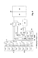
- In Fig. 4 ist als zweite Kommunikations-Ausführungsform eine OPC (Open Process Control) - Kommunikationsstruktur zwischen Leitstand und den Großgeräten dargestellt. Es ist wiederum die beispielhaft in Fig. 1 skizzierte Konfiguration mit den folgenden Richtfunk-Kommunikationen gezeigt:
- Richtfunk-Sektor 17 mit Richtantenne 2 des Leitstandes 1 und den zugeordneten Richtantennensystemen 8 bzw. 9 der Großgeräte 5 bzw. 6 sowie
- hintereinandergeschaltete Richtfunk-Sektoren 18/20 mit Richtantenne 3 des Leitstandes 1 und der zugeordneten Richtantenne 13 der Zwischenstation 12 sowie Richtantenne 14 der Zwischenstation 12 mit zugeordnetem Richtantennensystem 16 des Großgerätes 15 sowie
- Richtfunk-Sektor 19 mit Richtantenne 4 des Leitstandes 1 und zugeordnetem Richtantennensystem 10 des Großgerätes 7.
- Jedes Richtantennensystem 8 bzw. 9 bzw. 10 bzw. 16 ist mit einem Prozessportal (PPA) 37 bzw. 38 bzw. 39 bzw. 40 verbunden, wobei jedes Prozessportal eine Client-Station aufweist.
- Die automatisch nachgeführten Richtantennen 2, 3 und 4 sind über Kommunikationsmodule (z.B. Buskoppler) 25, 26 mit der Elektronik 45 des Leitstandes 1 verbunden, welche sich im wesentlichen aus einem Datenzugriffs-Server-Station 41 mit nachgeschaltetem zentralem Steuer/Regel-Netzwerk 42 zusammensetzt. Die Datenübertragungsrate zwischen den Übergangseinheiten 25, 26 und der Elektronik 45 kann beispielsweise 100 MBit/s sein.
- In Fig. 4 ist zusätzlich angedeutet, dass selbstverständlich weitere OPC- Client-Stationen 43 an die Elektronik 45 angeschlossen sein können. Ferner ist ohne Bezifferung der Funktionsblöcke gestrichelt angedeutet, dass sich in den einzelnen Richtfunk-Sektoren weitere Großgeräte bewegen können, welche jeweils automatisch nachgeführten Richtantennensysteme mit angeschlossenen Prozessportalen aufweisen.
- Die vorgeschlagene Lösungsgrundlage beruht auf einer Wireless- LAN- Kommunikation mittels einer nachgeführten Richtantenne. Die Nachführung der Richtantenne berücksichtigt die Position des Großgerätes in der Strosse und seine Rotation (Eigendrehung). Die Bewegung des Großgerätes in der Strosse erfolgt relativ zum Leitstand (Fixpunkt, trigonometrischer Punkt) und wird mittels Auswertung von GPS (Global Positioning System) - Koordinaten (Peilung) gegenüber der Nordrichtung berücksichtigt. Die Rotation des Großgerätes wird mittels "Kompass" Peilung gegenüber der Nordrichtung ermittelt. Die Auswertung dieser beiden Winkeländerungen gegenüber der Nordrichtung wird als Nachführwinkel für die erforderliche Antennenausrichtung genutzt.
- Das erfindungsgemäße Lösungsverfahren beruht auf den folgenden Kriterien:
- Es existiert mindestens eine feste Antenne (WLAN - Wireless Local Area Network - Antenne), deren Position genau bestimmt werden kann: siehe Richtantennen 2, 3, 4 des Leitstandes 1.
- Die Richtungsabweichung eines mobilen Großgerätes (siehe Ziffern 5, 6, 7, 15, eventuell 12) durch Eigenbewegung in Bezug zur festen Antenne (WLAN-Antenne) wird mittels Nachführung kompensiert: siehe Anordnung mit Schaltschrank 21 + Antennenrotor 22 + Mast 23 + Richtantenne 24.
- Die Nachführung der Antenne des Großgerätes berücksichtigt sowohl die Bewegung des Großgerätes in der Strosse (Fahrweg) als auch die aktuelle Rotation des Großgerätes.
- Folgende erfindungsgemäße Lösungsschritte sind vorgesehen:
- Die Nachführung der Antenne des Großgerätes erfolgt mittels des Antennenrotors 22. Selbstverständlich ist die Antennenrotorgeschwindigkeit größer als die mögliche Rotationsgeschwindigkeit des Großgerätes.
- Das Steuersignal zur Nachführung der Richtantenne des Großgerätes wird vorzugsweise in der im Großgerät üblicherweise vorhandenen Automatisierungstechnik erzeugt.
- Zur Berechnung des Steuersignals zur Nachführung der Antenne des Großgerätes werden die Winkelabweichung des Großgerätes gegenüber dem Nordpol und der Peilungswinkel (= Winkel zwischen dem gegenwärtigen Standort des Großgerätes und der festen Antenne) verwendet.
- Bei der Berechnung des Peilungswinkels zwischen Leitstand 1 und einem Großgerät werden das von einem GPS-Empfänger gelieferte Signal (aktuelle GPS-Koordinaten des Großgerätes), insbesondere die gelieferten 2D-Positionen des NMEA-GGA-Protokolls sowie mathematischen Grundlagen der sphärischen Trigonometrie benutzt.
- Die Abweichung durch Rotation des Großgerätes gegenüber dem Nordpol (Rotationswinkel) wird durch Auswertung eines am Großgerät montierten "Kompass" realisiert (z. B. magnetischen 3D-Feldsensors oder digitaler Kompass).
- Der achsensymmetrisch am Großgerät montierte magnetische 3D-Feldsensor (Kompass) wird in seiner Genauigkeit von den systembedingten Sensorparametern (Auflösung) und von dem "hard ironing"-Fehler (bedingt durch die Eisenkomponente des Großgerätes) und / oder dem "soft ironing"-Fehler (elektromagnetische Komponente, bedingt durch eingeschaltete Großverbraucher des Großgerätes) bestimmt. Um diese systembedingten Fehler zu minimieren, wird bei Erstinbetriebnahme mittels einer kompassgenauen Nordausrichtung des mobilen Großgerätes der "ironing offset" des magnetischen 3D-Feldsensors bestimmt und als Korrekturgröße in die Winkelberechnung der Nachführung einbezogen (Kalibrierung).
- Wird ein digitaler Kompass verwendet, wird das von diesem ausgegebene "heading" (Ausrichtung) als Rotationswinkel benutzt.
- Die Anzahl der Prozesskommunikationssignale wird durch die mögliche Bandbreite der WLAN-Antenne und die geforderte Reichweite bestimmt. Grundlage ist die Menge der übertragenen TCP/IP-Pakete (Transport Control Protocol / Internet Protocol
- Abhängig von der geforderten Kommunikationsart ist ein uni-/bidirektionaler Datenaustausch (OPC, siehe Anordnung gemäß Fig. 4) und/oder eine Client-Station / Server-Station - Kommunikation (siehe Anordnung gemäß Fig. 3) möglich. OPC (Open Process Control) bezeichnet dabei den internationalen Standard für Kommunikation in der Industrie und gewährleistet einen Datenaustausch mit "Fremdsystemen".
- Selbstverständlich wird zur Bestimmung der Rotation des Großgerätes die Deklination (Abweichung des "magnetischen" Nordpols vom "geografischen" Nordpol) am Einsatzort in die Berechnung der Rotation des Großgerätes einbezogen, desgleichen "unerwartete" Feldstärkeänderungen des Erdmagnetfeldes, welche sich nach erfolgter Kalibrierung - bei welcher das Steuerungsprogramm den "Normalwert" der Feldstärke berechnet und abspeichert - einstellen. Für die Kalibrierung des magnetischen 3 D-Feldsensors wird das Großgerät in mechanischer Nullstellung (Längsrichtung) mittels Handkompass nach Norden ausgerichtet. Die Richtantenne wird horizontal senkrecht zur Längsrichtung des Großgerätes montiert. Der Antennenrotor hat dabei die Position 0°. Die Drehrichtung der Richtantenne erfolgt im Uhrzeigersinn über Osten - Süden - Westen nach Norden (0 - 360°).
- Während des Betriebes des Großgerätes wird die aktuelle Feldstärke des Erdmagnetfeldes mit dem abgespeicherten "Normalwert" der Feldstärke verglichen und bei unzulässiger Abweichung wird die aktuell gemessene Richtungsabweichung gegenüber Nord nicht in die Berechnung des Antennennachführwinkels einbezogen. Die magnetischen Feldspulen des magnetischen 3 D-Feldsensors bilden das Erdmagnetfeld gegenüber Nord ab. Die Berechnung des aktuellen Rotationswinkels gegenüber Nord des Großgerätes erfolgt unter Einbezug der Deklination und "unerwarteter" Feldstärkeänderungen.
- Wie bereits vorstehend angedeutet, erfolgt eine Berechnung des Peilungswinkels zwischen dem zentralen Leitstand 1 und einem Großgerät unter Verwendung der GPS-Koordinaten des Leitstandes und des Großgerätes, wobei die Fahrgeschwindigkeit des Großgerätes in der Strosse die erzielbare Auflösungsgenauigkeit bei der Positionsbestimmung bestimmt. Die Schwankungen des vom GPS-Empfänger gelieferten Signals werden mittels Filterung geglättet. Die Filterung (Mittelwertbildung über einen vorgegebenen Zeitraum) erfolgt durch Berechnung der maximal zulässigen Änderung des Peilungswinkels als Funktion der Fahrgeschwindigkeit des mobilen Großgerätes in der Strosse.
- Der Antennennachführwinkel ist eine Funktion der aktuellen Position des Großgerätes innerhalb der Strosse in Bezug zum Leitstand 1 (Peilungswinkel) sowie dem aktuellen Rotationswinkel des Großgerätes:

- Folgende Datensignale sind beispielsweise zwischen Leitstand und den Großgeräten übertragbar:
- Messsignale von beliebigen Sensoren der Großgeräte,
- Rückmeldesignale von beliebigen Aktoren der Großgeräte,
- Steuersignale für Aktoren der Großgeräte,
- Parametersignale für Sensoren und Aktoren der Großgeräte.
- Auch wenn vorstehend der Leitstand 1 zugleich als trigonometrischer Punkt vorgeben ist, kann abweichend hiervon ein beliebiger Fixpunkt als trigonometrischer Punkt des Kommunikationssystems dienen.
- Für vorstehenden "Kompass" können 3D-Feldsensoren (magneto-induktive, magneto-resistive oder magnetische Fluxsensoren) verwendet werden, oder ein digitaler Kompass oder Kreiselkompass Anwendung finden.
Es können allgemein unterschiedliche Einrichtungen eingesetzt werden, wie - magneto-inductive-Sensor
- magneto-resistive-Sensor
- magnetic-flux-Sensor
- digitaler Magnetsensor
- Kreiselkompass
-
- 1
- Leitstand
- 2
- erste Richtantenne des Leitstandes
- 3
- zweite Richtantenne des Leitstandes
- 4
- dritte Richtantenne des Leitstandes
- 5
- mobiles Großgerät
- 6
- mobiles Großgerät
- 7
- mobiles Großgerät
- 8
- Richtantennensystem
- 9
- Richtantennensystem
- 10
- Richtantennensystem
- 11
- Strosse
- 12
- Zwischenstation
- 13
- erste Richtantenne der Zwischenstation
- 14
- zweite Richtantenne der Zwischenstation
- 15
- mobiles Großgerät
- 16
- Richtantennensystem
- 17
- Richtfunk-Sektor
- 18
- Richtfunk-Sektor
- 19
- Richtfunk-Sektor
- 20
- Richtfunk-Sektor
- 21
- Schaltschrank des Richtantennensystems
- 22
- Antennenrotor
- 23
- Mast
- 24
- Richtantenne
- 25
- Übergangseinheit (Buskoppler)
- 26
- Übergangseinheit (Buskoppler)
- 27
- Prozessportal inklusive Server-Station des Großgerätes 5
- 28
- Prozessportal inklusive Server-Station des Großgerätes 6
- 29
- Prozessportal inklusive Server-Station des Großgerätes 7
- 30
- Prozessportal inklusive Server-Station des Großgerätes 15
- 31
- Client-Station des Großgerätes 5
- 32
- Client-Station des Großgerätes 6
- 33
- Client-Station des Großgerätes 7
- 34
- Client-Station des Großgerätes 15
- 35
- Anzeigeeinheit
- 36
- Anzeigeeinheit
- 37
- Prozessportal inklusive Client-Station des Großgerätes 5
- 38
- Prozessportal inklusive Client-Station des Großgerätes 6
- 39
- Prozessportal inklusive Client-Station des Großgerätes 7
- 40
- Prozessportal inklusive Client-Station des Großgerätes 15
- 41
- Datenzugriffs-Server-Station
- 42
- Zentrales Steuer/Regel-Netzwerk
- 43
- weitere OPC Client-Stationen
- 44
- Elektronik des Leitstandes
- 45
- Elektronik des Leitstandes
Claims (14)
- Kommunikationssystem im Tagebau sowie Massengut-Umschlagplatz zur vorzugsweise bidirektionalen Übertragung von Informationen zwischen einem Leitstand (1) und mindestens einem mobilen Großgerät (5, 6, 7), dadurch gekennzeichnet, dass ein trigonometrischer Punkt als Fixpunkt des Kommunikationssystems vorgegeben ist, der eine Richtantenne (2, 3, 4) aufweist, welche einen Richtfunk-Sektor (17, 18, 19) definiert, innerhalb dessen sich mindestens ein Großgerät (5, 6, 7) bewegen kann, welches (5, 6, 7) über ein Richtantennensystem (8, 9, 10) verfügt, wobei eine automatische Ausrichtung der Richtfunk-Übertragungsstrecke zwischen dem trigonometrischen Punkt und dem Großgerät (5, 6, 7) erfolgt.
- Kommunikationssystem nach Anspruch 1, dadurch gekennzeichnet, dass sich im Endbereich eines Richtfunk-Sektors (17, 18, 19) eine Relaisstation (12) befindet, welche einerseits eine zur Richtantenne (2, 3, 4) des Richtfunk-Sektors (17, 18, 19) gerichtete Richtantenne (13) und andererseits eine weitere Richtantenne (14) aufweist, die einen weiteren Richtfunk-Sektor (20) definiert, innerhalb dessen sich mindestens ein Großgerät (15) mit automatisch nachgeführter Richtantennensystem (16) bewegen kann, so dass sich eine Hintereinanderschaltung beider Richtfunk-Sektoren (17, 18, 19, 20) ergibt.
- Kommunikationssystem nach Anspruch 1 und/oder 2, dadurch gekennzeichnet, dass der Leitstand (1) selbst als trigonometrischer Punkt vorgegeben ist.
- Kommunikationssystem nach einem der vorstehenden Ansprüche, dadurch gekennzeichnet, dass das automatisch nachgeführte Richtantennensystem (8, 9, 10, 16) eines Großgerätes (5, 6, 7, 15) in Abhängigkeit seiner aktuellen Position innerhalb des Richtfunk-Sektors (17, 18, 19, 20) und seiner aktuellen Rotation bzw. Eigendrehung nachgeführt wird.
- Kommunikationssystem nach Anspruch 4, dadurch gekennzeichnet, dass die Ermittlung der aktuellen Position des Großgerätes (5, 6, 7, 15) innerhalb des Richtfunk-Sektors (17, 18, 19, 20) durch Auswertung seiner GPS (Global Positioning System) -Koordinaten sowie der GPS-Koordinaten des trigonometrischen Punktes (1) erfolgt.
- Kommunikationssystem nach Anspruch 5, dadurch gekennzeichnet, dass eine Mittelwertbildung der GPS-Koordinaten über einen vorgegebenen Zeitraum erfolgt, wobei die Fahrgeschwindigkeit des Großgerätes (5, 6, 7, 15) berücksichtigt wird.
- Kommunikationssystem nach Anspruch 4, dadurch gekennzeichnet, dass die Ermittlung der aktuellen Rotation des Großgerätes (5, 6, 7, 15) durch Auswertung der Signale eines magnetischen oder vorzugsweise digitalen Kompasses erfolgt.
- Kommunikationssystem nach Anspruch 7, dadurch gekennzeichnet, dass die Deklination, d. h. Abweichung des "magnetischen" Nordpols vom "geografischen" Nordpol am Massengut-Umschlagplatz berücksichtigt wird.
- Kommunikationsstruktur nach Anspruch 7, dadurch gekennzeichnet, dass durch die Eisenkomponente eines Großgerätes (5, 6, 7, 15) bedingte Beeinflussungen beim Einsatz eines magnetischen Kompasses berücksichtigt werden.
- Kommunikationssystem nach Anspruch 7, dadurch gekennzeichnet, dass durch die elektromagnetische Komponente eines Großgerätes (5, 6, 7, 15) verursachte Beeinflussungen, bedingt durch eingeschaltete Großverbraucher des Großgerätes, berücksichtigt werden.
- Kommunikationssystem nach Anspruch 7, dadurch gekennzeichnet, dass "unerwartete" Feldstärkeänderungen des Erdmagnetfeldes erfasst und berücksichtigt werden.
- Kommunikationssystem nach einem der vorstehenden Ansprüche, dadurch gekennzeichnet, dass ein Antennenrotor (22) zur Nachführung eines Richtantennensystems (8, 9, 10, 16) eingesetzt ist.
- Kommunikationssystem nach einem der vorstehenden Ansprüche, dadurch gekennzeichnet, dass eine Client-Station/Server- Station- Kommunikationsstruktur zwischen dem trigonometrischen Punkt (1) und dem mindestens einen Großgerät (5, 6, 7, 15) vorliegt.
- Kommunikationssystem nach einem der vorstehenden Ansprüche, dadurch gekennzeichnet, dass eine OPC (Open Process Control)-Kommunikationsstruktur zwischen dem trigonometrischen Punkt (1) und dem mindestens einen Großgerät (5, 6, 7, 15) vorliegt.
Priority Applications (1)
| Application Number | Priority Date | Filing Date | Title |
|---|---|---|---|
| PL05013301T PL1612997T3 (pl) | 2004-07-01 | 2005-06-21 | Radioliniowy system komunikacyjny dla kopalni odkrywkowych i miejsc przeładunku materiałów masowych |
Applications Claiming Priority (1)
| Application Number | Priority Date | Filing Date | Title |
|---|---|---|---|
| DE102004031817A DE102004031817B3 (de) | 2004-07-01 | 2004-07-01 | Kommunikationssystem im Tagebau oder für den Einsatz auf einem Massengut-Umschlagplatz |
Publications (2)
| Publication Number | Publication Date |
|---|---|
| EP1612997A1 true EP1612997A1 (de) | 2006-01-04 |
| EP1612997B1 EP1612997B1 (de) | 2012-12-19 |
Family
ID=34937566
Family Applications (1)
| Application Number | Title | Priority Date | Filing Date |
|---|---|---|---|
| EP05013301A Expired - Lifetime EP1612997B1 (de) | 2004-07-01 | 2005-06-21 | Richtfunk-Kommunikationssystem für Tagebau oder Massengut-Umschlagplatz |
Country Status (4)
| Country | Link |
|---|---|
| EP (1) | EP1612997B1 (de) |
| DE (1) | DE102004031817B3 (de) |
| ES (1) | ES2401440T3 (de) |
| PL (1) | PL1612997T3 (de) |
Families Citing this family (2)
| Publication number | Priority date | Publication date | Assignee | Title |
|---|---|---|---|---|
| US8463569B2 (en) * | 2011-03-21 | 2013-06-11 | Caterpillar Trimble Control Technologies Llc | Method of operating a magnetic compass on a machine |
| DE102012004569A1 (de) * | 2012-03-09 | 2013-09-12 | Hauk & Sasko Ingenieurgesellschaft Mbh | System und Verfahren zum Betrieb einer Halde |
Citations (6)
| Publication number | Priority date | Publication date | Assignee | Title |
|---|---|---|---|---|
| DE4011316A1 (de) | 1990-04-07 | 1991-10-17 | Rheinische Braunkohlenw Ag | Verfahren zur bestimmung der geodaetischen standortes von teilen eines ortsbeweglichen grossgeraetes |
| US20010003443A1 (en) * | 1996-10-10 | 2001-06-14 | Scott R. Velazquez | Communication system using geographic position data |
| EP0994987B1 (de) | 1997-07-10 | 2002-04-10 | Siemens Aktiengesellschaft | Schaufelradgerät |
| EP1341326A1 (de) * | 2002-02-26 | 2003-09-03 | Alcatel | Wiederherstellung einer Verbindung in einem ortsfesten drahtlosen Übertragungsnetzwerk |
| EP1369954A2 (de) | 2002-06-05 | 2003-12-10 | Fujitsu Limited | Adaptive Antenneneinheit für Mobilgerät |
| WO2004040803A1 (en) * | 2002-10-25 | 2004-05-13 | Harris Corporation | Method and device for establishing communication links and detecting interference between mobile nodes in a communication system |
Family Cites Families (2)
| Publication number | Priority date | Publication date | Assignee | Title |
|---|---|---|---|---|
| US5274844A (en) * | 1992-05-11 | 1993-12-28 | Motorola, Inc. | Beam pattern equalization method for an adaptive array |
| DE19535441A1 (de) * | 1995-09-23 | 1997-03-27 | Bosch Gmbh Robert | Antenne einer Zentralstation eines Punkt-zu-Mehrpunkt-Richtfunksystems |
-
2004
- 2004-07-01 DE DE102004031817A patent/DE102004031817B3/de not_active Expired - Fee Related
-
2005
- 2005-06-21 EP EP05013301A patent/EP1612997B1/de not_active Expired - Lifetime
- 2005-06-21 PL PL05013301T patent/PL1612997T3/pl unknown
- 2005-06-21 ES ES05013301T patent/ES2401440T3/es not_active Expired - Lifetime
Patent Citations (6)
| Publication number | Priority date | Publication date | Assignee | Title |
|---|---|---|---|---|
| DE4011316A1 (de) | 1990-04-07 | 1991-10-17 | Rheinische Braunkohlenw Ag | Verfahren zur bestimmung der geodaetischen standortes von teilen eines ortsbeweglichen grossgeraetes |
| US20010003443A1 (en) * | 1996-10-10 | 2001-06-14 | Scott R. Velazquez | Communication system using geographic position data |
| EP0994987B1 (de) | 1997-07-10 | 2002-04-10 | Siemens Aktiengesellschaft | Schaufelradgerät |
| EP1341326A1 (de) * | 2002-02-26 | 2003-09-03 | Alcatel | Wiederherstellung einer Verbindung in einem ortsfesten drahtlosen Übertragungsnetzwerk |
| EP1369954A2 (de) | 2002-06-05 | 2003-12-10 | Fujitsu Limited | Adaptive Antenneneinheit für Mobilgerät |
| WO2004040803A1 (en) * | 2002-10-25 | 2004-05-13 | Harris Corporation | Method and device for establishing communication links and detecting interference between mobile nodes in a communication system |
Also Published As
| Publication number | Publication date |
|---|---|
| EP1612997B1 (de) | 2012-12-19 |
| DE102004031817B3 (de) | 2005-11-17 |
| PL1612997T3 (pl) | 2013-05-31 |
| ES2401440T3 (es) | 2013-04-19 |
Similar Documents
| Publication | Publication Date | Title |
|---|---|---|
| DE60209412T2 (de) | System und Verfahren zur Navigation und Kommunikation | |
| DE69511542T2 (de) | Positionsgeber | |
| DE68911100T2 (de) | System zum Ausrichten der Antenne auf Satelliten. | |
| DE102004055033A1 (de) | Arbeitsgeländeverfolgungssystem und -verfahren | |
| EP0025193A1 (de) | Leitsystem für den Individualverkehr und Verfahren zur Übertragung von Leitinformationen | |
| DE2156110C3 (de) | Gerat zum Bestimmen des Rollwinkels eines Bohrkopfes | |
| EP0423162B1 (de) | Vermessungssystem mit einer elektrooptischen totalstation und einer mobilen empfangsstation eines satelliten-positionsmess-systems | |
| DE20206267U1 (de) | Vakuumpumpe | |
| DE69831481T2 (de) | Verfahren zur Störpegelsschätzung in einem Funksystem | |
| EP1612997B1 (de) | Richtfunk-Kommunikationssystem für Tagebau oder Massengut-Umschlagplatz | |
| EP1828491A1 (de) | System zur lageerfassung | |
| DE60225394T2 (de) | Verfahren und Sytem zur geographischen Ortung in Kommunikations- Netzwerken und Terminal dafür | |
| EP3249353A1 (de) | Optoelektronisches messgerät mit magnetkompass und kompensationsfunktionalität | |
| DE19741701A1 (de) | Verfahren und Einrichtung zum Umbuchen einer Mobilstation bei einem Mobilfunksystem | |
| EP4248119B1 (de) | System zur ermittlung von prädiktionsdaten | |
| DE112024000512T5 (de) | Kommunikationssystem | |
| DE102005006389B4 (de) | Verfahren zur Positionsbestimmung eines mobilen Objekts, insbesondere einer landwirtschaftlichen Arbeitsmaschine | |
| DE102004018445A1 (de) | Positionsanzeigesystem und dieses System verwendende Positionsanzeigevorrichtung | |
| EP1501153A1 (de) | Vorrichtung und Verfahren zur Überprüfung der Ausrichtung einer Antennenanlage | |
| DE102013218775B4 (de) | System zum Ausrichten einer Richtfunkantenne | |
| DE20200218U1 (de) | Mess-System | |
| DE102019206462A1 (de) | Verfahren, Ortungssignalempfänger und Ortungssystem | |
| EP0826980B1 (de) | DGPS-Ortungssystem | |
| EP1374614A2 (de) | Verfahren zum testen eines mobilfunksystems | |
| WO2013120527A1 (de) | Funknetzanordnung für ein bauwerk |
Legal Events
| Date | Code | Title | Description |
|---|---|---|---|
| PUAI | Public reference made under article 153(3) epc to a published international application that has entered the european phase |
Free format text: ORIGINAL CODE: 0009012 |
|
| AK | Designated contracting states |
Kind code of ref document: A1 Designated state(s): AT BE BG CH CY CZ DE DK EE ES FI FR GB GR HU IE IS IT LI LT LU MC NL PL PT RO SE SI SK TR |
|
| AX | Request for extension of the european patent |
Extension state: AL BA HR LV MK YU |
|
| 17P | Request for examination filed |
Effective date: 20060523 |
|
| AKX | Designation fees paid |
Designated state(s): AT BE BG CH CY CZ DE DK EE ES FI FR GB GR HU IE IS IT LI LT LU MC NL PL PT RO SE SI SK TR |
|
| 17Q | First examination report despatched |
Effective date: 20070205 |
|
| GRAP | Despatch of communication of intention to grant a patent |
Free format text: ORIGINAL CODE: EPIDOSNIGR1 |
|
| RIC1 | Information provided on ipc code assigned before grant |
Ipc: H01Q 3/26 20060101ALI20120831BHEP Ipc: H04L 12/28 20060101AFI20120831BHEP Ipc: H04B 1/00 20060101ALI20120831BHEP Ipc: H04B 17/02 20060101ALI20120831BHEP |
|
| RAP1 | Party data changed (applicant data changed or rights of an application transferred) |
Owner name: ABB AG |
|
| GRAS | Grant fee paid |
Free format text: ORIGINAL CODE: EPIDOSNIGR3 |
|
| GRAA | (expected) grant |
Free format text: ORIGINAL CODE: 0009210 |
|
| AK | Designated contracting states |
Kind code of ref document: B1 Designated state(s): AT BE BG CH CY CZ DE DK EE ES FI FR GB GR HU IE IS IT LI LT LU MC NL PL PT RO SE SI SK TR |
|
| REG | Reference to a national code |
Ref country code: GB Ref legal event code: FG4D Free format text: NOT ENGLISH |
|
| REG | Reference to a national code |
Ref country code: CH Ref legal event code: EP |
|
| REG | Reference to a national code |
Ref country code: AT Ref legal event code: REF Ref document number: 589866 Country of ref document: AT Kind code of ref document: T Effective date: 20130115 |
|
| REG | Reference to a national code |
Ref country code: DE Ref legal event code: R096 Ref document number: 502005013344 Country of ref document: DE Effective date: 20130221 |
|
| REG | Reference to a national code |
Ref country code: ES Ref legal event code: FG2A Ref document number: 2401440 Country of ref document: ES Kind code of ref document: T3 Effective date: 20130419 |
|
| PG25 | Lapsed in a contracting state [announced via postgrant information from national office to epo] |
Ref country code: LT Free format text: LAPSE BECAUSE OF FAILURE TO SUBMIT A TRANSLATION OF THE DESCRIPTION OR TO PAY THE FEE WITHIN THE PRESCRIBED TIME-LIMIT Effective date: 20121219 Ref country code: SE Free format text: LAPSE BECAUSE OF FAILURE TO SUBMIT A TRANSLATION OF THE DESCRIPTION OR TO PAY THE FEE WITHIN THE PRESCRIBED TIME-LIMIT Effective date: 20121219 |
|
| REG | Reference to a national code |
Ref country code: NL Ref legal event code: VDEP Effective date: 20121219 |
|
| REG | Reference to a national code |
Ref country code: GR Ref legal event code: EP Ref document number: 20130400557 Country of ref document: GR Effective date: 20130418 |
|
| REG | Reference to a national code |
Ref country code: LT Ref legal event code: MG4D |
|
| PG25 | Lapsed in a contracting state [announced via postgrant information from national office to epo] |
Ref country code: SI Free format text: LAPSE BECAUSE OF FAILURE TO SUBMIT A TRANSLATION OF THE DESCRIPTION OR TO PAY THE FEE WITHIN THE PRESCRIBED TIME-LIMIT Effective date: 20121219 |
|
| REG | Reference to a national code |
Ref country code: PL Ref legal event code: T3 |
|
| PG25 | Lapsed in a contracting state [announced via postgrant information from national office to epo] |
Ref country code: EE Free format text: LAPSE BECAUSE OF FAILURE TO SUBMIT A TRANSLATION OF THE DESCRIPTION OR TO PAY THE FEE WITHIN THE PRESCRIBED TIME-LIMIT Effective date: 20121219 Ref country code: BG Free format text: LAPSE BECAUSE OF FAILURE TO SUBMIT A TRANSLATION OF THE DESCRIPTION OR TO PAY THE FEE WITHIN THE PRESCRIBED TIME-LIMIT Effective date: 20130319 Ref country code: SK Free format text: LAPSE BECAUSE OF FAILURE TO SUBMIT A TRANSLATION OF THE DESCRIPTION OR TO PAY THE FEE WITHIN THE PRESCRIBED TIME-LIMIT Effective date: 20121219 Ref country code: IS Free format text: LAPSE BECAUSE OF FAILURE TO SUBMIT A TRANSLATION OF THE DESCRIPTION OR TO PAY THE FEE WITHIN THE PRESCRIBED TIME-LIMIT Effective date: 20130419 Ref country code: CY Free format text: LAPSE BECAUSE OF FAILURE TO SUBMIT A TRANSLATION OF THE DESCRIPTION OR TO PAY THE FEE WITHIN THE PRESCRIBED TIME-LIMIT Effective date: 20121219 |
|
| PGFP | Annual fee paid to national office [announced via postgrant information from national office to epo] |
Ref country code: GB Payment date: 20130619 Year of fee payment: 9 Ref country code: CH Payment date: 20130621 Year of fee payment: 9 Ref country code: DE Payment date: 20130620 Year of fee payment: 9 |
|
| PG25 | Lapsed in a contracting state [announced via postgrant information from national office to epo] |
Ref country code: NL Free format text: LAPSE BECAUSE OF FAILURE TO SUBMIT A TRANSLATION OF THE DESCRIPTION OR TO PAY THE FEE WITHIN THE PRESCRIBED TIME-LIMIT Effective date: 20121219 Ref country code: PT Free format text: LAPSE BECAUSE OF FAILURE TO SUBMIT A TRANSLATION OF THE DESCRIPTION OR TO PAY THE FEE WITHIN THE PRESCRIBED TIME-LIMIT Effective date: 20130419 Ref country code: RO Free format text: LAPSE BECAUSE OF FAILURE TO SUBMIT A TRANSLATION OF THE DESCRIPTION OR TO PAY THE FEE WITHIN THE PRESCRIBED TIME-LIMIT Effective date: 20121219 |
|
| PGFP | Annual fee paid to national office [announced via postgrant information from national office to epo] |
Ref country code: GR Payment date: 20130618 Year of fee payment: 9 Ref country code: FR Payment date: 20130703 Year of fee payment: 9 Ref country code: FI Payment date: 20130613 Year of fee payment: 9 Ref country code: IT Payment date: 20130624 Year of fee payment: 9 Ref country code: PL Payment date: 20130524 Year of fee payment: 9 |
|
| PLBE | No opposition filed within time limit |
Free format text: ORIGINAL CODE: 0009261 |
|
| STAA | Information on the status of an ep patent application or granted ep patent |
Free format text: STATUS: NO OPPOSITION FILED WITHIN TIME LIMIT |
|
| PG25 | Lapsed in a contracting state [announced via postgrant information from national office to epo] |
Ref country code: DK Free format text: LAPSE BECAUSE OF FAILURE TO SUBMIT A TRANSLATION OF THE DESCRIPTION OR TO PAY THE FEE WITHIN THE PRESCRIBED TIME-LIMIT Effective date: 20121219 |
|
| 26N | No opposition filed |
Effective date: 20130920 |
|
| BERE | Be: lapsed |
Owner name: ABB A.G. Effective date: 20130630 |
|
| REG | Reference to a national code |
Ref country code: DE Ref legal event code: R097 Ref document number: 502005013344 Country of ref document: DE Effective date: 20130920 |
|
| PG25 | Lapsed in a contracting state [announced via postgrant information from national office to epo] |
Ref country code: MC Free format text: LAPSE BECAUSE OF FAILURE TO SUBMIT A TRANSLATION OF THE DESCRIPTION OR TO PAY THE FEE WITHIN THE PRESCRIBED TIME-LIMIT Effective date: 20121219 |
|
| REG | Reference to a national code |
Ref country code: IE Ref legal event code: MM4A |
|
| PG25 | Lapsed in a contracting state [announced via postgrant information from national office to epo] |
Ref country code: BE Free format text: LAPSE BECAUSE OF NON-PAYMENT OF DUE FEES Effective date: 20130630 |
|
| PG25 | Lapsed in a contracting state [announced via postgrant information from national office to epo] |
Ref country code: IE Free format text: LAPSE BECAUSE OF NON-PAYMENT OF DUE FEES Effective date: 20130621 |
|
| PGFP | Annual fee paid to national office [announced via postgrant information from national office to epo] |
Ref country code: CZ Payment date: 20140617 Year of fee payment: 10 |
|
| REG | Reference to a national code |
Ref country code: DE Ref legal event code: R119 Ref document number: 502005013344 Country of ref document: DE |
|
| PG25 | Lapsed in a contracting state [announced via postgrant information from national office to epo] |
Ref country code: FI Free format text: LAPSE BECAUSE OF NON-PAYMENT OF DUE FEES Effective date: 20140621 |
|
| REG | Reference to a national code |
Ref country code: CH Ref legal event code: PL |
|
| REG | Reference to a national code |
Ref country code: AT Ref legal event code: MM01 Ref document number: 589866 Country of ref document: AT Kind code of ref document: T Effective date: 20140621 |
|
| GBPC | Gb: european patent ceased through non-payment of renewal fee |
Effective date: 20140621 |
|
| REG | Reference to a national code |
Ref country code: GR Ref legal event code: ML Ref document number: 20130400557 Country of ref document: GR Effective date: 20150105 |
|
| REG | Reference to a national code |
Ref country code: FR Ref legal event code: ST Effective date: 20150227 |
|
| REG | Reference to a national code |
Ref country code: DE Ref legal event code: R119 Ref document number: 502005013344 Country of ref document: DE Effective date: 20150101 |
|
| PG25 | Lapsed in a contracting state [announced via postgrant information from national office to epo] |
Ref country code: DE Free format text: LAPSE BECAUSE OF NON-PAYMENT OF DUE FEES Effective date: 20150101 Ref country code: IT Free format text: LAPSE BECAUSE OF NON-PAYMENT OF DUE FEES Effective date: 20140621 Ref country code: LI Free format text: LAPSE BECAUSE OF NON-PAYMENT OF DUE FEES Effective date: 20140630 Ref country code: CH Free format text: LAPSE BECAUSE OF NON-PAYMENT OF DUE FEES Effective date: 20140630 |
|
| PG25 | Lapsed in a contracting state [announced via postgrant information from national office to epo] |
Ref country code: GR Free format text: LAPSE BECAUSE OF NON-PAYMENT OF DUE FEES Effective date: 20150105 Ref country code: GB Free format text: LAPSE BECAUSE OF NON-PAYMENT OF DUE FEES Effective date: 20140621 Ref country code: FR Free format text: LAPSE BECAUSE OF NON-PAYMENT OF DUE FEES Effective date: 20140630 Ref country code: AT Free format text: LAPSE BECAUSE OF NON-PAYMENT OF DUE FEES Effective date: 20140621 |
|
| PG25 | Lapsed in a contracting state [announced via postgrant information from national office to epo] |
Ref country code: TR Free format text: LAPSE BECAUSE OF FAILURE TO SUBMIT A TRANSLATION OF THE DESCRIPTION OR TO PAY THE FEE WITHIN THE PRESCRIBED TIME-LIMIT Effective date: 20121219 |
|
| REG | Reference to a national code |
Ref country code: ES Ref legal event code: FD2A Effective date: 20150730 |
|
| PG25 | Lapsed in a contracting state [announced via postgrant information from national office to epo] |
Ref country code: HU Free format text: LAPSE BECAUSE OF FAILURE TO SUBMIT A TRANSLATION OF THE DESCRIPTION OR TO PAY THE FEE WITHIN THE PRESCRIBED TIME-LIMIT; INVALID AB INITIO Effective date: 20050621 Ref country code: LU Free format text: LAPSE BECAUSE OF NON-PAYMENT OF DUE FEES Effective date: 20130621 |
|
| REG | Reference to a national code |
Ref country code: PL Ref legal event code: LAPE |
|
| PG25 | Lapsed in a contracting state [announced via postgrant information from national office to epo] |
Ref country code: ES Free format text: LAPSE BECAUSE OF NON-PAYMENT OF DUE FEES Effective date: 20140622 |
|
| PG25 | Lapsed in a contracting state [announced via postgrant information from national office to epo] |
Ref country code: PL Free format text: LAPSE BECAUSE OF NON-PAYMENT OF DUE FEES Effective date: 20140621 |
|
| PG25 | Lapsed in a contracting state [announced via postgrant information from national office to epo] |
Ref country code: CZ Free format text: LAPSE BECAUSE OF NON-PAYMENT OF DUE FEES Effective date: 20150621 |