EP1612909A1 - Integrierte Stromversorgungsschaltung mit Rückführungskreis - Google Patents
Integrierte Stromversorgungsschaltung mit Rückführungskreis Download PDFInfo
- Publication number
- EP1612909A1 EP1612909A1 EP05013692A EP05013692A EP1612909A1 EP 1612909 A1 EP1612909 A1 EP 1612909A1 EP 05013692 A EP05013692 A EP 05013692A EP 05013692 A EP05013692 A EP 05013692A EP 1612909 A1 EP1612909 A1 EP 1612909A1
- Authority
- EP
- European Patent Office
- Prior art keywords
- power
- electrical
- power supply
- supply information
- integrated circuit
- Prior art date
- Legal status (The legal status is an assumption and is not a legal conclusion. Google has not performed a legal analysis and makes no representation as to the accuracy of the status listed.)
- Granted
Links
Images

Classifications
-
- G—PHYSICS
- G05—CONTROLLING; REGULATING
- G05F—SYSTEMS FOR REGULATING ELECTRIC OR MAGNETIC VARIABLES
- G05F1/00—Automatic systems in which deviations of an electric quantity from one or more predetermined values are detected at the output of the system and fed back to a device within the system to restore the detected quantity to its predetermined value or values, i.e. retroactive systems
- G05F1/66—Regulating electric power
-
- G—PHYSICS
- G05—CONTROLLING; REGULATING
- G05B—CONTROL OR REGULATING SYSTEMS IN GENERAL; FUNCTIONAL ELEMENTS OF SUCH SYSTEMS; MONITORING OR TESTING ARRANGEMENTS FOR SUCH SYSTEMS OR ELEMENTS
- G05B15/00—Systems controlled by a computer
- G05B15/02—Systems controlled by a computer electric
-
- H—ELECTRICITY
- H02—GENERATION; CONVERSION OR DISTRIBUTION OF ELECTRIC POWER
- H02J—CIRCUIT ARRANGEMENTS OR SYSTEMS FOR SUPPLYING OR DISTRIBUTING ELECTRIC POWER; SYSTEMS FOR STORING ELECTRIC ENERGY
- H02J1/00—Circuit arrangements for dc mains or dc distribution networks
- H02J1/06—Two-wire systems
-
- H—ELECTRICITY
- H02—GENERATION; CONVERSION OR DISTRIBUTION OF ELECTRIC POWER
- H02J—CIRCUIT ARRANGEMENTS OR SYSTEMS FOR SUPPLYING OR DISTRIBUTING ELECTRIC POWER; SYSTEMS FOR STORING ELECTRIC ENERGY
- H02J13/00—Circuit arrangements for providing remote indication of network conditions, e.g. an instantaneous record of the open or closed condition of each circuitbreaker in the network; Circuit arrangements for providing remote control of switching means in a power distribution network, e.g. switching in and out of current consumers by using a pulse code signal carried by the network
- H02J13/00002—Circuit arrangements for providing remote indication of network conditions, e.g. an instantaneous record of the open or closed condition of each circuitbreaker in the network; Circuit arrangements for providing remote control of switching means in a power distribution network, e.g. switching in and out of current consumers by using a pulse code signal carried by the network characterised by monitoring
-
- Y—GENERAL TAGGING OF NEW TECHNOLOGICAL DEVELOPMENTS; GENERAL TAGGING OF CROSS-SECTIONAL TECHNOLOGIES SPANNING OVER SEVERAL SECTIONS OF THE IPC; TECHNICAL SUBJECTS COVERED BY FORMER USPC CROSS-REFERENCE ART COLLECTIONS [XRACs] AND DIGESTS
- Y02—TECHNOLOGIES OR APPLICATIONS FOR MITIGATION OR ADAPTATION AGAINST CLIMATE CHANGE
- Y02B—CLIMATE CHANGE MITIGATION TECHNOLOGIES RELATED TO BUILDINGS, e.g. HOUSING, HOUSE APPLIANCES OR RELATED END-USER APPLICATIONS
- Y02B90/00—Enabling technologies or technologies with a potential or indirect contribution to GHG emissions mitigation
- Y02B90/20—Smart grids as enabling technology in buildings sector
-
- Y—GENERAL TAGGING OF NEW TECHNOLOGICAL DEVELOPMENTS; GENERAL TAGGING OF CROSS-SECTIONAL TECHNOLOGIES SPANNING OVER SEVERAL SECTIONS OF THE IPC; TECHNICAL SUBJECTS COVERED BY FORMER USPC CROSS-REFERENCE ART COLLECTIONS [XRACs] AND DIGESTS
- Y02—TECHNOLOGIES OR APPLICATIONS FOR MITIGATION OR ADAPTATION AGAINST CLIMATE CHANGE
- Y02E—REDUCTION OF GREENHOUSE GAS [GHG] EMISSIONS, RELATED TO ENERGY GENERATION, TRANSMISSION OR DISTRIBUTION
- Y02E60/00—Enabling technologies; Technologies with a potential or indirect contribution to GHG emissions mitigation
-
- Y—GENERAL TAGGING OF NEW TECHNOLOGICAL DEVELOPMENTS; GENERAL TAGGING OF CROSS-SECTIONAL TECHNOLOGIES SPANNING OVER SEVERAL SECTIONS OF THE IPC; TECHNICAL SUBJECTS COVERED BY FORMER USPC CROSS-REFERENCE ART COLLECTIONS [XRACs] AND DIGESTS
- Y04—INFORMATION OR COMMUNICATION TECHNOLOGIES HAVING AN IMPACT ON OTHER TECHNOLOGY AREAS
- Y04S—SYSTEMS INTEGRATING TECHNOLOGIES RELATED TO POWER NETWORK OPERATION, COMMUNICATION OR INFORMATION TECHNOLOGIES FOR IMPROVING THE ELECTRICAL POWER GENERATION, TRANSMISSION, DISTRIBUTION, MANAGEMENT OR USAGE, i.e. SMART GRIDS
- Y04S10/00—Systems supporting electrical power generation, transmission or distribution
- Y04S10/30—State monitoring, e.g. fault, temperature monitoring, insulator monitoring, corona discharge
-
- Y—GENERAL TAGGING OF NEW TECHNOLOGICAL DEVELOPMENTS; GENERAL TAGGING OF CROSS-SECTIONAL TECHNOLOGIES SPANNING OVER SEVERAL SECTIONS OF THE IPC; TECHNICAL SUBJECTS COVERED BY FORMER USPC CROSS-REFERENCE ART COLLECTIONS [XRACs] AND DIGESTS
- Y04—INFORMATION OR COMMUNICATION TECHNOLOGIES HAVING AN IMPACT ON OTHER TECHNOLOGY AREAS
- Y04S—SYSTEMS INTEGRATING TECHNOLOGIES RELATED TO POWER NETWORK OPERATION, COMMUNICATION OR INFORMATION TECHNOLOGIES FOR IMPROVING THE ELECTRICAL POWER GENERATION, TRANSMISSION, DISTRIBUTION, MANAGEMENT OR USAGE, i.e. SMART GRIDS
- Y04S20/00—Management or operation of end-user stationary applications or the last stages of power distribution; Controlling, monitoring or operating thereof
Definitions
- Different electrical circuits and/or devices may be designed to operate using electrical power having a variety of characteristics. Even electrical circuits and/or devices designed to receive electrical power at an identical voltage level may have different power supply needs. For example, some circuits or devices may operate well over a larger voltage range than others. Also for example, some circuits or devices may operate better under noisy conditions than other circuits. Even a particular electrical circuit or device may utilize electrical power differently and have different power needs at various points in time. For example, the amount of electrical energy consumed in a circuit or device may vary in accordance with varying utilization of various circuit components or sub-components.
- Characteristics of electrical power supplied to electrical circuits, or components thereof may vary over time. For example, the power supply providing the electrical power may exhibit inconsistent behavior. Further for example, the consumption of energy by one or more circuit components may affect characteristics of electrical power provided to other components. For example an increased utilization of current by a first electrical component may result in a voltage and/or current decrease to a second electrical device.
- a power management integrated circuit comprising:
- Figure 1 shows a block diagram of a system comprising an exemplary power management integrated circuit utilizing received power supply information, in accordance with various aspects of the present invention.
- FIG. 2 shows a block diagram of a system comprising an exemplary power management integrated circuit utilizing received power supply information, in accordance with various aspects of the present invention.
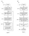
- Figure 3 illustrates a flow diagram of a method for providing regulated signal(s) corresponding to electrical power(s) from a power management integrated circuit utilizing received power supply information, in accordance with various aspects of the present invention.
- Figure 4 illustrates a flow diagram of a method for providing regulated signal(s) corresponding to electrical power(s) from a power management integrated circuit utilizing power supply information received from a plurality of sources, in accordance with various aspects of the present invention.
- FIG. 1 shows a block diagram of a system 100 comprising an exemplary power management integrated circuit 110 utilizing received power supply information, in accordance with various aspects of the present invention.
- the power management integrated circuit 110 may comprise any of a variety of general integrated circuit characteristics.
- the power management integrated circuit 110 may also comprise various aspects of known power regulation or generation circuitry.
- the power management integrated circuit 110 may also comprise various aspects of circuitry that is not related to power regulation or generation. Accordingly, the scope of various aspects of the present invention should not be limited by characteristics of particular integrated circuitry, particular power regulation or generation circuitry, or particular circuitry that is not related to power regulation or generation.
- modules may be implemented in hardware, software or a combination thereof. Further, portions of modules may be shared. For example, a first module may share various hardware and/or software components with a second module. Accordingly, the scope of various aspects of the present invention should not be limited by characteristics of a specific implementation of a module or by arbitrary boundaries between modules.
- the exemplary power management integrated circuit 110 may comprise a communication interface module 120.
- the communication interface module 120 may receive power supply information 107 from at least one electrical device 105 external to the integrated circuit 110. Also, for example, the communication interface module 120 may receive power supply information 109 from at least one electrical device 108 internal to the integrated circuit 110. Though the following discussion will generally discuss an exemplary scenario including an electrical device external to the integrated circuit 110, the scope of various aspects of the present invention should by no means be limited by such externality.
- Such power supply information 107 may, for example, comprise information related to a first electrical power. Such power supply information 107 may, for example, also comprise information related to a second electrical power and/or nth electrical power.
- the external electrical device(s) 105 may, for example, receive and utilize the first electrical power. Alternatively, for example, the external electrical device(s) 105 may communicate power supply information 107 that originates at other electrical devices that utilize the first electrical power. Similarly, in an exemplary scenario involving a second or nth electrical power, the external electrical device(s) 105 may, for example, receive and utilize the second or nth electrical power. Alternatively, in an exemplary scenario, the external electrical device(s) 105 may communicate power supply information 107 that originates at other electrical devices that utilize the second or nth electrical power. Further for example, the external electrical device(s) 105 may comprise one or more devices that monitor power supply characteristics.
- the external electrical device(s) 105 may comprise characteristics of any of a large variety of electrical devices.
- the external electrical device(s) 105 may comprise characteristics of analog and/or digital circuitry.
- the external electrical device(s) 105 may, for example, comprise passive or active components.
- the external electrical device(s) 105 may, for example, comprise an integrated circuit.
- the external device(s) 105 may comprise characteristics of processing circuitry, communication circuitry, control circuitry, user interface circuitry, etc. Accordingly, the scope of various aspects of the present invention should not be limited by characteristics of particular external electrical devices.
- the power supply information 107 received by the communication interface module 120 may comprise characteristics of any of a variety of power supply information.
- the power supply information 107 may comprise information related to power supply voltage level (e.g., voltage level of power received by a device or desired voltage level for power received by a device).
- the power supply information 107 may comprise information of any of a variety of characteristics of electrical power. Such characteristics may, for example and without limitation, comprise voltage variability characteristics (e.g., ripple, noise, stability, switching frequency, etc.), load response characteristics, various current-related power characteristics, energy-efficiency characteristics, etc.
- Such power supply information 107 may, for example, comprise absolute or relative values.
- the power supply information 107 may comprise general data communication information (e.g., source and/or destination information). The scope of various aspects of the present invention should not be limited by any particular power characteristics.
- the power supply information 107 may, for example, comprise analog and/or digital information. Accordingly, the communication interface module 120 may comprise analog and/or digital communication capability. In an exemplary scenario, the power supply information 107 may comprise power supply information of a single power supply characteristic (e.g., voltage) represented by a voltage level on a single wire. In another exemplary scenario, the power supply information 107 may comprise multiplexed digital information from a plurality of sources and concerning a plurality of power supply characteristics of a plurality of electrical powers. Such multiplexed digital information may, for example, be communicated over any of a variety of digital communication bus types, including various serial or parallel bus architectures.
- a single power supply characteristic e.g., voltage
- the power supply information 107 may comprise multiplexed digital information from a plurality of sources and concerning a plurality of power supply characteristics of a plurality of electrical powers. Such multiplexed digital information may, for example, be communicated over any of a variety of digital communication bus types, including various serial or parallel bus architecture
- the signal processing capability of the communication interface module 120 may vary, depending on circuit architecture.
- the communication interface module 120 may comprise no more than a conduit through which power supply information may flow from an external device to a power regulator module or other module of the integrated circuit 110.
- the communication interface module 120 may comprise digital signal processing circuitry, which processes received digital power supply information and directs at least a portion of such digital power supply information to an appropriate power regulator module or other module of the integrated circuit 110.
- the communication interface module 120 may comprise capability to communicate digital information over various media and utilizing any of a variety of communication protocols.
- the communication interface module 120 may comprise the capability to communicate power supply information over a conductor or over wireless or optical interfaces.
- the communication interface module 120 may comprise capability to communicate power supply information with external devices utilizing various contention-based (e.g., CSMA, CSMA/CD, ALOHA, etc.) or contention-free (e.g., various token or polling-based) communication protocols.
- the communication interface module 120 may, for example, comprise capability to communicate power supply information synchronously or asynchronously.
- the communication interface module 120 may communicate power supply information utilizing any of a variety of communication media and any of a variety of communication protocols. Accordingly, the scope of various aspects of the present invention should not be limited by characteristics of a particular communication media or protocol.
- the exemplary integrated circuit 110 may comprise a first power regulator module 130.
- the first power regulator module 130 may, for example, receive at least a portion of the power supply information 107 received by the communication interface module 120, and process such power supply information to determine a first regulated power signal 135, where the first regulated power signal 135 is based at least in part on the processed power supply information.
- the first regulated power signal 135 may correspond to the first electrical power to which the received power supply information 107 is related.
- the first regulated power signal 135 may, for example, correspond to the first electrical power in any of a variety of manners, three non-exclusive examples of which are illustrative in Figure 2, which will be discussed later.
- the first regulated power signal 135 may comprise the first electrical power.
- the first power regulator module 130 might generate the first electrical power using only electrical components internal to the integrated circuit 110 or might utilize electrical components (e.g., power supply circuitry) external to the integrated circuit 110.
- the first regulated power signal 135 may comprise a signal that interacts with power supply circuitry external to the integrated circuit 110, which in turn generates the first electrical power.
- the first power regulator module 130 may comprise characteristics of any of a variety of power regulator circuits.
- the first power regulator module 130 may comprise characteristics of at least a front-end portion (if not a whole portion) of a linear voltage regulator, a switching regulator (e.g., a buck converter, boost converter, buck-boost converter, charge pump, etc.), or other types of known or yet to be developed regulator circuits. Accordingly, the scope of various aspects of the present invention should not be limited by characteristics of a particular type of voltage regulator circuit or portion thereof.
- such external circuitry may comprise electrical components in any of a variety of configurations.
- such electrical component configurations may comprise at least portions of a buck converter, boost converter, buck-boost converter, charge pump, or other types of known or yet to be developed power regulator circuits. Accordingly, the scope of various aspects of the present invention should not be limited by characteristics of particular regulator circuit architectures.
- the first power regulator module 130 may determine a first regulated power signal 135 based at least in part on a portion of the power supply information 107, wherein the first regulated power signal 135 corresponds to the first electrical power.
- the first power regulator module 130 may make such a determination in any of a variety of manners, depending on the particular operating scenario.
- the first power regulator module 130 may determine one or more characteristics of the first electrical power based, at least in part, on a portion of the power supply information 107. The first power regulator module 130 may then determine the first regulated power signal 135 based on the determined characteristic(s).
- the power supply information 107 may comprise information of a desired voltage level for the first electrical power.
- the first power regulator module 130 may receive information of the desired voltage level from the communication interface module 120 and determine the first regulated power signal 135 based on such information.
- the first power regulator module 130 may output a first regulated power signal 135 that comprises the first electrical power characterized by the desired voltage level (or other voltage level based on the desired voltage level).
- the first power regulator module 130 may output the first regulated power signal 135 that, when interacting with circuitry external to the integrated circuit 110, causes the external circuitry to output the first electrical power characterized by the desired voltage level.
- the power supply information 107 may comprise information of maximum desired voltage variability.
- the first power regulator module 130 may receive information of the maximum desired voltage variability from the communication interface module 120 and determine the first regulated power signal 135 based on such information. For example, the first power regulator module 130 may directly output a first regulated power signal 135 that comprises the first electrical power characterized by the maximum desired voltage variability (or voltage variability based on the maximum desired voltage variability). Also for example, the first power regulator module 130 may output the first regulated power signal 135 that, when interacting with circuitry external to the integrated circuit 110, causes the external circuitry to output the first electrical power characterized by the maximum desired voltage variability.
- the power supply information 107 may comprise information of a minimum energy-efficiency level.
- the first power regulator module 130 may receive information of the minimum energy-efficiency level from the communication interface module 120 and determine the first regulated power signal 135 based on such information. For example, the first power regulator module 130 may directly output a first regulated power signal 135 that comprises the first electrical power characterized by the minimum energy-efficiency level (or energy-efficiency level based on the minimum energy-efficiency level). Also for example, the first power regulator module 130 may output the first regulated power signal 135 that, when interacting with circuitry external to the integrated circuit 110, causes the external circuitry to output the first electrical power characterized by the minimum energy-efficiency level.
- the first power regulator module 130 may determine a first regulated power signal 135 based at least in part on a portion of the power supply information 107, wherein the first regulated power signal 135 corresponds to the first electrical power. Accordingly, the scope of various aspects of the present invention should not be limited by characteristics of any particular type of power supply information or a particular manner of determining a regulated power signal based on such information.
- the first power regulator module 130 may, for example, process power supply information that is received (e.g., through the communication interface module 120) from a plurality of electrical devices external to the integrated circuit 110.
- the first power regulator module 130 may, in various scenarios, process such power supply information to arbitrate between power supply needs of the plurality of electrical devices.
- Such arbitration may, for example and without limitation, comprise determining characteristics of the first electrical power (and thus, the corresponding first regulated power signal 135) based, at least in part, on respective priority of the plurality of electrical devices.
- the first power regulator module 130 may determine characteristics of the first electrical power based solely on the electrical device with the highest priority.
- the first power regulator module 130 may determine characteristics of the first electrical power based on a priority-based weighted average of power supply needs of the electrical devices. Further for example, the first power regulator module 130 may determine characteristics of the first electrical power by averaging respective power supply needs of the electrical devices.
- the first power regulator module 130 may, in determining characteristics of the first electrical power (and thus, the corresponding first regulated power signal 135), may arbitrate between needs of a plurality of electrical devices. Accordingly, the scope of various aspects of the present invention should not be limited by characteristics of any particular manner of performing such arbitration.
- the first power regulator module 130 may generate and output the first regulated power signal 135 to at least one electrical device external to the power management integrated circuit 110.
- the external electrical device may comprise characteristics of any of a variety of electrical devices.
- the first power regulator module 130 may output the first regulated power signal 135 to power supply circuitry.
- the first regulated power signal 135 may, for example, cause such power supply circuitry to output the first electrical power having desired characteristics.
- Such power supply circuitry will be discussed in more detailed in the discussion of Figure 2.
- the power supply circuitry may then, for example, output the first electrical power to one or more electrical devices, some of which may provide power supply information 107 to the integrated circuit 110 through the communication interface module 120.
- the first power regulator module 130 may output the first regulated power signal 135 directly to an external electrical device that, in turn, transmits power supply information 107 to the integrated circuit 110.
- the first power regulator module 130 may output the first regulated power signal 135 (e.g., comprising the first electrical power) to a first electrical device external to the integrated circuit 110.
- the exemplary first electrical device may, in turn, communicate power supply information 107 (e.g., information of desired and/or received voltage or variance level of the first electrical power) to the integrated circuit 110 (e.g., through the communication interface module 120).
- the exemplary power management integrated circuit 110 may also, for example, comprise a second power regulator module 140.
- the second power regulator module 140 may, for example and without limitation, share various characteristics with the exemplary first power regulator module 130 discussed previously.
- the second power regulator module 140 may determine a second regulated power signal 145 based at least in part on a portion of the power supply information 107 ( e.g ., as received by the communication interface module 120), wherein the second regulated power signal 145 corresponds to second electrical power.
- the second power regulator module 140 may then output the second regulated power signal 145 to at least one electrical device external to the power management integrated circuit.
- FIG 2 shows a block diagram of a system 200 comprising an exemplary power management integrated circuit 210 utilizing received power supply information, in accordance with various aspects of the present invention.
- the exemplary system 200 may, for example and without limitation, share various characteristics with the exemplary system 100 illustrated in Figure 1 and discussed previously.
- the exemplary power management integrated circuit 210 may comprise a communication interface module 220.
- the exemplary communication interface module 220 may, for example and without limitation, share various characteristics with the exemplary communication interface module 120 illustrated in Figure 1 and discussed previously.
- the communication interface module 220 may receive power supply information 207 from at least one electrical device 205 external to the integrated circuit 210.
- the communication interface module 220 may also, for example, receive power supply information from at least one electrical device internal to the integrated circuit 210. Though such an internal electrical device is not illustrated in Figure 2 and the following discussion will generally discuss an exemplary scenario including an electrical device external to the integrated circuit 210, the scope of various aspects of the present invention should by no means be limited by such externality
- Such power supply information may, for example, comprise information related to a first electrical power.
- Such power supply information may, for example, also comprise information related to a second electrical power and/or nth electrical power.
- the electrical device(s) 205 may also, for example and without limitation, share various characteristics with the exemplary electrical device(s) 105 illustrated in Figure 1 and discussed previously.
- the exemplary integrated circuit 210 may also comprise one or more regulator control modules 225 that process at least a portion 221 of the power supply information 207 received by the communication interface module 220 and generates regulator control signals 226-228.
- the regulator control module(s) 225 may, for example, generate the regulator control signals 226-228 based, at least in part, on at least a portion 221 of the power supply information 207.
- the individual power regulator modules 130, 140 processed at least a portion of the power supply information to determine and/or generate respective regulated power signals 135, 145.
- the regulator control module(s) 225 At least a portion of such processing is performed by the regulator control module(s) 225.
- the one or more regulator control module(s) 225 may be at least partially integrated (e.g., in hardware and/or software), which may foster a more centralized approach for determining the plurality of regulator control signals 226-228 than the more distributed approach exemplified by the system 100 illustrated in Figure 1.
- the regulator control signals 226-228 may control various operational aspects of respective power regulator modules 230, 240, 250.
- the regulator control signals 226-228 may comprise characteristics of any of a variety of control signals.
- the regulator control signals 226-228 may comprise information of various power supply goals, which the respective power regulator modules 230, 240, 250 are to meet.
- the regulator control signals 226-228 may comprise target voltage and/or current level information.
- the regulator control signals 226-228 may comprise information of target power supply variability limits and/or noise limits.
- the regulator control signals 226-228 may comprise information of load response goals that the power regulator modules 230, 240, 250 are to meet.
- the regulator control signals 226-228 may comprise information controlling various specific operational aspects of respective power regulator modules 230, 240, 250.
- the regulator control signals 226-228 may comprise information for directly controlling switching behavior (e.g., duty cycle, switching frequency, etc.) in the respective power regulator modules 230, 240, 250.
- the regulator control signals 226-228 may control various operational aspects of respective power regulator modules 230, 240, 250. Accordingly, the scope of various aspects of the present invention should not be limited by characteristics of particular regulator control signals and/or information.
- the exemplary integrated circuit 210 may comprise first, second and third power regulator modules 230, 240, 250.
- the power regulator modules 230, 240, 250 may, for example and without limitation, share various characteristics with the exemplary power regulator modules 130, 140 illustrated in Figure 1 and discussed previously.
- the first regulator module 230 may receive the first regulator control signal 226 from the regulator control module(s) 225.
- the first power regulator module 230 may then, for example, determine a first regulated power signal 235 based at least in part on the first regulator control signal 226, where the first regulated power signal 235 corresponds to first electrical power ( e.g ., the first electrical power to which at least a portion of the received power supply information is related).
- the first regulated power signal 235 may correspond to the first electrical power in any of a variety of manners.
- the first regulated power signal 235 comprises the first electrical power.
- the first power regulator module 230 might, for example, generate the first regulated power signal 235 (comprising the first electrical power) utilizing only circuitry internal to the integrated circuit 210.
- the second power regulator module 240 may, for example, receive the second regulator control signal 227 from the regulator control module(s) 225. The second power regulator module 240 may then, for example, determine a second regulated power signal 245 based at least in part on the second regulator control signal 227, where the second regulated power signal 245 corresponds to second electrical power (e.g., second electrical power to which at least a portion of the received power supply information is related).
- second electrical power e.g., second electrical power to which at least a portion of the received power supply information is related.
- the second regulated power signal 245 may correspond to the second electrical power in any of a variety of manners.
- the second regulated power signal 245 comprises the second electrical power.
- the second power regulator module 240 may, for example, generate the second regulated power signal 245 (comprising the second electrical power) in conjunction with power supply circuitry 246 external to the integrated circuit 210.
- such external power supply circuitry 246 may comprise various switching power supply circuitry (e.g., electrical components in a boost converter configuration).
- the third power regulator module 250 may, for example, receive the third regulator control signal 228 from the regulator control module(s) 225. The third power regulator module 250 may then, for example, determine a third regulated power signal 255 based at least in part on the third regulator control signal 228, where the third regulated power signal 255 corresponds to third electrical power (e.g., third electrical power to which at least a portion of the received power supply information is related).
- third electrical power e.g., third electrical power to which at least a portion of the received power supply information is related.
- the third regulated power signal 255 may correspond to the third electrical power in any of a variety of manners.
- the third regulated power signal 255 comprises one or more signals or subsignals that cause power supply circuitry 256 external to the integrated circuit 210 to output the third electrical power 257.
- such external power supply circuitry 256 may comprise various switching power supply circuitry (e.g., electrical components in a buck converter configuration).
- Figure 3 illustrates a flow diagram of a method 300 for providing regulated signal(s) corresponding to electrical power(s) from a power management integrated circuit utilizing received power supply information, in accordance with various aspects of the present invention.
- the exemplary method 300 may, for example and without limitation, share various characteristics with the functionality discussed previously with regard to the exemplary systems 100, 200 illustrated in Figures 1-2 and discussed previously.
- the exemplary method 300 may begin at step 310.
- the method 300 (and other methods discussed herein) may begin for any of a variety of reasons.
- the method 300 may begin automatically in response to a power-up or reset condition.
- the method 300 may begin in response to a command, either from a user or from a system component.
- the method 300 may execute periodically or in response to a detected system or environmental condition. Accordingly, the scope of various aspects of the present invention should not be limited by characteristics of any particular initiating cause or condition.
- the exemplary method 300 may, at step 320, comprise determining initial characteristics of first electrical power.
- Step 320 may comprise determining such characteristics in any of variety of manners.
- step 320 may comprise determining such initial characteristics by utilizing default characteristics or utilizing stored information of previous characteristics.
- Step 320 may also, for example, comprise determining initial characteristics of a first regulated power signal that corresponds to first electrical power. Such correspondence was generally discussed previously in the discussion of Figure 1.
- step 320 may comprise determining such initial characteristics by utilizing default characteristics or utilizing stored information of previous characteristics.
- step 320 may comprise determining initial characteristics of first electrical power and/or initial characteristics of a corresponding first regulated power signal. Accordingly, the scope of various aspects of the present invention should not be limited by a particular manner of determining initial characteristics of electrical power or corresponding signals.
- the exemplary method 300 may, at step 330, comprise outputting the first regulated power signal (e.g., as determined at step 320 or step 350, to be discussed later) to at least one electrical device external (or internal) to the integrated circuit.
- Step 330 may, for example and without limitation, share various functional characteristics with the exemplary power regulator modules 130, 140, 230, 240, 250 discussed previously with regard to Figures 1-2.
- the following discussion generally refers to an electrical device external to the integrated circuit, the scope of various aspects of the present invention should by no means be limited by such externality.
- the electrical device may, in accordance with various aspects of the present invention, be internal to the integrated circuit.
- step 330 may comprise outputting the first regulated power signal to power supply circuitry external to the integrated circuit.
- power supply circuitry may, for example, provide the first electrical power to at least one electrical device (e.g., an electrical device that might provide power supply information, as received at step 340, to be discussed later).
- step 330 may comprise outputting the first regulated power signal directly to at least one electrical device (e.g., an electrical device that might provide power supply information, as received at step 340, to be discussed later).
- step 330 may comprise outputting the first regulated power signal to at least one electrical device external to the power management integrated circuit. Accordingly, the scope of various aspects of the present invention should not be limited by characteristics of a particular regulated power signal or particular electrical device(s) external to the integrated circuit.
- the exemplary method 300 may, at step 340, comprise receiving power supply information from one or more electrical devices external to the power management integrated circuit.
- the power supply information may, for example, comprise information related to a first electrical power.
- Step 340 may, for example and without limitation, share various functional characteristics with the exemplary communication interface modules 120, 220 illustrated in Figures 1-2 and discussed previously.
- the power supply information may comprise information related to various characteristics of electrical power. Such characteristics may, for example and without limitation, comprise voltage and/or current level, voltage and/or current variability, noise, ripple, load response characteristics, energy efficiency level, etc.
- the power supply information may, for example, comprise analog and/or digital information.
- Step 340 may, for example, comprise receiving the power supply information in any of a variety of manners.
- step 340 may comprise receiving the power supply information over an analog or digital communication link.
- the communication link may, for example, be serial or parallel.
- the communication link may, for example, comprise a dedicated information bus or a shared information bus.
- Step 340 may, for example, comprise receiving the power supply information utilizing any of a large variety of communication media and/or communication protocols.
- Step 340 may comprise receiving the power supply information from any of a variety of devices external to the power management integrated circuit.
- step 340 may comprise receiving the power supply information from at least one electrical device that receives and utilizes the first electrical power (e.g., corresponding to the regulated power signal output at step 330).
- step 340 may comprise receiving the power supply information from an electrical device monitoring operation of another device that receives and utilizes the first electrical power.
- step 340 may comprise receiving the power supply information from an electrical device that is communicatively coupled to an electrical device that receives and utilizes the first electrical power.
- step 340 may comprise receiving the power supply information from an electrical device associated with the production of the first electrical power. Accordingly, the scope of various aspects of the present invention should not be limited by characteristics of a particular device that step 340 might receive power supply information from.
- the exemplary method 300 may, at step 350, comprise determining a first regulated power signal based, at least in part, on a portion of the power supply information (e.g., as received at step 340).
- the first regulated power signal may, for example, correspond to the first electrical power.
- Step 350 may, for example and without limitation, share various functional characteristics with the power regulator modules 130, 140, 230, 240, 250 and the regulator control module 225 illustrated in Figures 1-2 and discussed previously.
- the first regulated power signal may comprise the first electrical power.
- step 350 might comprise generating the first electrical power using only electrical components internal to the integrated circuit or utilizing electrical components (e.g., power supply circuitry) external to the integrated circuit.
- the first regulated power signal may comprise a signal that interacts with power supply circuitry external to the integrated circuit, which in turn generates the first electrical power.
- Step 350 might comprise utilizing any of a variety of power regulator circuitry.
- step 350 might comprise utilizing circuitry comprising characteristics of at least a front-end portion (if not a whole portion) of a linear voltage regulator, a switching regulator (e.g., a buck converter, boost converter, buck-boost converter, charge pump, etc.), or other types of known or yet to be developed regulator circuits. Accordingly, the scope of various aspects of the present invention should not be limited by characteristics of particular type of circuitry that step 350 might utilize.
- the first regulated power signal (e.g ., as output by step 330) interacts with circuitry external to the integrated circuit to provide the first electrical power
- external circuitry may comprise electrical components in any of a variety of configurations.
- electrical component configurations may comprise at least portions of a buck converter, boost converter, buck-boost converter, charge pump, or other types of known or yet to be developed power regulator circuits. Accordingly, the scope of various aspects of the present invention should not be limited by characteristics of particular power supply or power regulator circuitry architectures.
- step 350 may comprise determining a first regulated power signal based at least in part on a portion of the power supply information, where the first regulated power signal corresponds to the first electrical power. Step 350 may comprise making such a determination in any of a variety of manners, depending on the particular operating scenario.
- step 350 may comprise determining one or more characteristics of the first electrical power based, at least in part, on a portion of the power supply information. Step 350 may then, for example, comprise determining the first regulated power signal based on the determined characteristic(s).
- the power supply information may comprise information of a desired voltage level for the first electrical power.
- Step 350 may, for example, comprise determining the first regulated power signal based on such information.
- step 350 may comprise directly outputting a first regulated power signal that comprises the first electrical power characterized by the desired voltage level (or other voltage level based on the desired voltage level).
- step 350 may comprise outputting a first regulated power signal that, when interacting with circuitry external to the integrated circuit, causes the external circuitry to output the first electrical power characterized by the desired voltage level (or other voltage level based on the desired voltage level).
- the power supply information may comprise information of maximum desired voltage variability.
- Step 350 may, for example, comprise determining the first regulated power signal based on such information.
- step 350 may comprise directly outputting a first regulated power signal that comprises the first electrical power characterized by the maximum desired voltage variability (or voltage variability based on the maximum desired voltage variability).
- step 350 may comprise outputting a first regulated power signal that, when interacting with circuitry external to the integrated circuit, causes the external circuitry to output the first electrical power characterized by the maximum desired voltage variability (or voltage variability based on the maximum desired voltage variability).
- the power supply information may comprise information of a minimum energy-efficiency level.
- Step 350 may comprise determining the first regulated power signal based on such information.
- step 350 may comprise directly outputting a first regulated power signal that comprises the first electrical power characterized by the minimum energy-efficiency level (or energy-efficiency level based on the minimum energy-efficiency level).
- step 350 may comprise outputting a first regulated power signal that, when interacting with circuitry external to the integrated circuit, causes the external circuitry to output the first electrical power characterized by the minimum energy-efficiency level (or energy-efficiency level based on the minimum energy-efficiency level).
- step 350 may comprise determining a first regulated power signal based at least in part on a portion of the power supply information, wherein the first regulated power signal corresponds to the first electrical power. Accordingly, the scope of various aspects of the present invention should not be limited by characteristics of any particular type of power supply information or a particular manner of determining a regulated power signal based on such information.
- step 350 the execution flow of the exemplary method 300 may flow back up to step 330, which may output the first regulated power signal as determined by step 350.
- step 330 may output the first regulated power signal as determined by step 350.
- the previous discussion of the exemplary method 300 discussed determining and outputting a single first regulated power signal.
- a single regulated power signal was discussed for illustrative purposes only and should not limit the scope of various aspects of the present invention.
- the method 300 is readily extensible to determining and outputting a plurality of regulated power signals, which may, for example, correspond to a plurality of respective electrical powers or may correspond to a common electrical power.
- the power supply information received at step 340 may comprise information related to a second electrical power.
- Step 350 may then, for example, comprise determining a second regulated power signal based at least in part on a portion of the power supply information, where the second regulated power signal corresponds to the second electrical power.
- the exemplary method 300 may similarly, for example, extend to receiving power supply information related to n electrical powers, and determining and outputting one or more regulated power signals corresponding to the n electrical powers. Accordingly, the scope of various aspects of the present invention should not be limited by the determination and generation of a single regulated power signal.
- Figure 4 illustrates a flow diagram of a method 400 for providing regulated signal(s) corresponding to electrical power(s) from a power management integrated circuit utilizing power supply information received from a plurality of sources, in accordance with various aspects of the present invention.
- the method 400 may, for example and without limitation, share various functional characteristics with the exemplary systems 100, 200 illustrated in Figures 1-2 and discussed previously.
- the method 400 may also, for example and without limitation, share various characteristics with the exemplary method 300 illustrated in Figure 3 and discussed previously.
- various aspects of the present invention may receive and process power supply information from a plurality of sources.
- the exemplary method 400 provides a non-limiting exemplary illustration of such receipt and processing.
- the method 400, or various portions thereof, may for example, be executed in conjunction with the exemplary method 300 illustrated in Figure 3.
- the method 400 may be executed independently. Accordingly, the scope of various aspects of the present invention should not be limited by characteristics of method independence or interrelationship with other methods.
- the exemplary method 400 may, at step 420, comprise receiving power supply information from a first electrical device external (or internal) to the integrated circuit, where the power supply information comprises information related to a first electrical power.
- the exemplary method 400 may, at step 430, comprise receiving power supply information from a second electrical device external to the integrated circuit, where the power supply information comprises information related to the first electrical power.
- Steps 420 and 430 may, for example and without limitation, share various characteristics with step 340 of the exemplary method 300 illustrated in Figure 3 and discussed previously. Also, steps 420 and 430 may share various functional characteristics with the communication interface modules 120, 200 illustrated in Figures 1-2 and discussed previously. Note that though the present discussion will focus on receiving and processing power supply information from first and second external devices, the discussion is readily extensible to an n-device scenario and/or a scenario including one or more electrical devices internal to the integrated circuit.
- the exemplary method 400 may, at step 440, comprise determining a first regulated power signal based at least in part on a portion of the power supply information, where the first regulated power signal corresponds to the first electrical power.
- Step 440 may, for example and without limitation, share various characteristics with step 350 of the exemplary method 300 illustrated in Figure 3 and discussed previously.
- step 440 may comprise first processing the power supply information to determine one or more characteristics of the first electrical power. Step 440 may then, for example, output the first regulated power signal comprising the first electrical power having the determined characteristic(s). Alternatively for example, step 440 may determine characteristics of the first regulated power signal, which when output, will cause other circuitry to output the first electrical power having the determined characteristic(s).
- step 440 may comprise arbitrating between power supply needs of the first and second (or n) devices from which the power supply information was received. Such arbitration may, for example and without limitation, comprise determining characteristics of the first electrical power (and thus, the corresponding first regulated power signal) based, at least in part, on priority of the electrical devices. For example, step 440 may comprise determining characteristics of the first electrical power based solely on the electrical device with the highest priority. Alternatively for example, step 440 may comprise determining characteristics of the first electrical power based on a priority-based weighted average of power supply needs of the electrical devices. Further for example, step 440 may comprise determining characteristics of the first electrical power by averaging respective power supply needs of the electrical devices.
- exemplary step 440 may, in determining characteristics of the first electrical power and/or characteristics of the corresponding first regulated power signal, may arbitrate between needs of a plurality of electrical devices. Accordingly, the scope of various aspects of the present invention should not be limited by characteristics of any particular manner of performing such arbitration.
- the exemplary method 400 may, at step 450, comprise outputting the first regulated power signal to at least one electrical device external to the integrated circuit.
- Step 450 may, for example and without limitation, share various characteristics with step 330 of the exemplary method 300 illustrated in Figure 3 and discussed previously.
- step 450 execution flow of the exemplary method 400 may flow to step 460 for performing continued processing.
- continued processing may comprise any of variety of continued processing characteristics, including stopping, looping back to a previous method 400 step, entering a wait state, etc. Accordingly, the scope of various aspects of the present invention should not be limited by characteristics of any particular type of continued processing.
- the previous discussion of the exemplary method 400 discussed determining and outputting a single first regulated power signal.
- a single regulated power signal was discussed for illustrative purposes only and should not limit the scope of various aspects of the present invention.
- the method 400 is readily extensible to determining and outputting a plurality of regulated power signals, which may, for example, correspond to a plurality of respective electrical powers or may correspond to a common electrical power.
- the power supply information received at steps 420 and 430 may comprise information related to a second electrical power.
- Step 440 may then, for example, comprise determining a second regulated power signal based at least in part on a portion of the power supply information, where the second regulated power signal corresponds to the second electrical power.
- the exemplary method 400 may similarly, for example, extend to receiving power supply information related to n electrical powers, and determining and outputting one or more regulated power signals corresponding to the n electrical powers. Accordingly, the scope of various aspects of the present invention should not be limited by the determination and generation of a single regulated power signal.
Applications Claiming Priority (2)
| Application Number | Priority Date | Filing Date | Title |
|---|---|---|---|
| US58408804P | 2004-06-29 | 2004-06-29 | |
| US11/158,141 US7581122B2 (en) | 2004-06-29 | 2005-06-21 | Power supply integrated circuit with feedback control |
Publications (2)
| Publication Number | Publication Date |
|---|---|
| EP1612909A1 true EP1612909A1 (de) | 2006-01-04 |
| EP1612909B1 EP1612909B1 (de) | 2011-11-30 |
Family
ID=34981308
Family Applications (1)
| Application Number | Title | Priority Date | Filing Date |
|---|---|---|---|
| EP05013692A Active EP1612909B1 (de) | 2004-06-29 | 2005-06-24 | Integrierte Stromversorgungsschaltung mit Rückführungskreis |
Country Status (3)
| Country | Link |
|---|---|
| US (3) | US7581122B2 (de) |
| EP (1) | EP1612909B1 (de) |
| TW (1) | TWI302238B (de) |
Cited By (1)
| Publication number | Priority date | Publication date | Assignee | Title |
|---|---|---|---|---|
| US11331741B2 (en) | 2011-08-18 | 2022-05-17 | Illinois Tool Works Inc. | System and device operating using a welding power bus |
Families Citing this family (24)
| Publication number | Priority date | Publication date | Assignee | Title |
|---|---|---|---|---|
| US7295949B2 (en) * | 2004-06-28 | 2007-11-13 | Broadcom Corporation | Energy efficient achievement of integrated circuit performance goals |
| US7707434B2 (en) * | 2004-06-29 | 2010-04-27 | Broadcom Corporation | Power control bus for carrying power control information indicating a power supply voltage variability |
| US7509507B2 (en) * | 2004-06-29 | 2009-03-24 | Broadcom Corporation | Multi-regulator power supply chip with common control bus |
| US7925906B2 (en) * | 2004-06-29 | 2011-04-12 | Broadcom Corporation | Multi-voltage multi-battery power management unit |
| US7581122B2 (en) * | 2004-06-29 | 2009-08-25 | Broadcom Corporation | Power supply integrated circuit with feedback control |
| US7783924B2 (en) * | 2005-08-26 | 2010-08-24 | General Electric Company | System and method for communication between a controller and a power supply using a communication interface |
| US8401219B2 (en) | 2007-01-05 | 2013-03-19 | Apple Inc. | Headset connector |
| JP2007201455A (ja) * | 2005-12-28 | 2007-08-09 | Matsushita Electric Ind Co Ltd | 半導体集積回路装置 |
| US7782222B2 (en) * | 2006-02-28 | 2010-08-24 | Realtek Semiconductor Corp. | Voltage regulating power supply for noise sensitive circuits |
| US8180093B2 (en) * | 2007-01-05 | 2012-05-15 | Apple Inc. | Assembly for coupling the housings of an electronic device |
| US9118990B2 (en) | 2007-01-06 | 2015-08-25 | Apple Inc. | Connectors designed for ease of use |
| EP2421101B1 (de) | 2007-01-06 | 2013-09-11 | Apple Inc. | Headsetanschluss zur selektiven Weiterleitung von Signalen in Abhängigkeit der bestimmten Ausrichtung des angeschlossenen Steckverbinders |
| CN104202689B (zh) | 2007-01-06 | 2018-07-20 | 苹果公司 | 依照确定的啮合连接器的方向选择性路由信号的耳机连接器 |
| TWI381261B (zh) * | 2008-07-18 | 2013-01-01 | Asia Optical Co Inc | 電源管理裝置以及電源管理方法 |
| US8559865B2 (en) | 2008-07-31 | 2013-10-15 | Qualcomm Incorporated | Method and apparatus for providing jammer detection in a receiver |
| CN102255395B (zh) * | 2011-06-27 | 2014-11-05 | 华为终端有限公司 | 电子设备和单个电源向至少两个不同负载供电的方法 |
| US9141166B2 (en) * | 2011-12-13 | 2015-09-22 | Intel Corporation | Method, apparatus, and system for energy efficiency and energy conservation including dynamic control of energy consumption in power domains |
| US9292025B2 (en) | 2011-12-19 | 2016-03-22 | Mediatek Singapore Pte. Ltd. | Performance, thermal and power management system associated with an integrated circuit and related method |
| JP5672251B2 (ja) | 2012-01-27 | 2015-02-18 | 株式会社デンソー | 車両用電源供給制御装置 |
| JP6145669B2 (ja) * | 2012-03-27 | 2017-06-14 | パナソニックIpマネジメント株式会社 | 電力管理装置および電力管理システム |
| KR20140029565A (ko) * | 2012-08-28 | 2014-03-11 | 삼성전자주식회사 | 전력 제어 방법 및 장치 |
| US9119162B2 (en) * | 2013-02-19 | 2015-08-25 | Qualcomm Incorporated | Parallel arrangement of asynchronous buck converters for advanced power capability |
| TWI533553B (zh) | 2014-10-21 | 2016-05-11 | 國立清華大學 | 功率流管理方法與控制器 |
| US10582284B2 (en) | 2015-09-30 | 2020-03-03 | Apple Inc. | In-ear headphone |
Citations (1)
| Publication number | Priority date | Publication date | Assignee | Title |
|---|---|---|---|---|
| US20040123164A1 (en) | 2002-12-21 | 2004-06-24 | Power-One Limited | Method and system for controlling and monitoring an array of point-of-load regulators |
Family Cites Families (17)
| Publication number | Priority date | Publication date | Assignee | Title |
|---|---|---|---|---|
| US5483656A (en) | 1993-01-14 | 1996-01-09 | Apple Computer, Inc. | System for managing power consumption of devices coupled to a common bus |
| US6356984B1 (en) | 1998-06-30 | 2002-03-12 | Sun Microsystems, Inc. | Digital data processing system having a data bus and a control bus |
| US6668328B1 (en) | 1999-05-19 | 2003-12-23 | Globespanvirata, Inc. | Computer system having a power supply for coupling signals to a power line network and transmitting infrared signal to at least one peripheral card |
| US6396169B1 (en) | 2000-02-29 | 2002-05-28 | 3Com Corporation | Intelligent power supply control for electronic systems requiring multiple voltages |
| US6594771B1 (en) | 2000-04-13 | 2003-07-15 | Hewlett-Packard Development Company, L.P. | Method and apparatus for managing power in an electronic device |
| US6823465B2 (en) | 2001-04-30 | 2004-11-23 | Intel Corporation | Establishment of voltage of a terminal at a voltage level in response to validating the indication of the voltage to be supplied to the terminal |
| FI116702B (fi) | 2001-12-20 | 2006-01-31 | Nokia Corp | Dynaaminen tehonsäätö integroiduissa piireissä |
| KR100505638B1 (ko) | 2002-08-28 | 2005-08-03 | 삼성전자주식회사 | 워킹 콘텍스트 저장 및 복구 장치 및 방법 |
| US6949916B2 (en) | 2002-11-12 | 2005-09-27 | Power-One Limited | System and method for controlling a point-of-load regulator |
| US7209719B2 (en) | 2003-01-28 | 2007-04-24 | Gateway Inc. | Home power line network connected phone |
| US7085943B2 (en) | 2003-09-26 | 2006-08-01 | Freescale Semiconductor, Inc. | Method and circuitry for controlling supply voltage in a data processing system |
| US7105950B2 (en) * | 2003-09-26 | 2006-09-12 | Hewlett-Packard Development Company, L.P. | Power management in a system having a plurality of power supplies |
| US7203849B2 (en) * | 2003-12-12 | 2007-04-10 | Hewlett-Packard Development Company, L.P. | Method and system for distributing power to networked devices |
| US7190210B2 (en) | 2004-03-25 | 2007-03-13 | Integral Wave Technologies, Inc. | Switched-capacitor power supply system and method |
| US7509507B2 (en) * | 2004-06-29 | 2009-03-24 | Broadcom Corporation | Multi-regulator power supply chip with common control bus |
| US7581122B2 (en) * | 2004-06-29 | 2009-08-25 | Broadcom Corporation | Power supply integrated circuit with feedback control |
| US7308590B2 (en) | 2004-10-15 | 2007-12-11 | Intel Corporation | Automatic dynamic processor operating voltage control |
-
2005
- 2005-06-21 US US11/158,141 patent/US7581122B2/en active Active
- 2005-06-24 EP EP05013692A patent/EP1612909B1/de active Active
- 2005-06-28 TW TW094121606A patent/TWI302238B/zh active
-
2009
- 2009-08-18 US US12/542,865 patent/US8868935B2/en active Active
-
2014
- 2014-10-14 US US14/513,879 patent/US9285815B2/en active Active
Patent Citations (1)
| Publication number | Priority date | Publication date | Assignee | Title |
|---|---|---|---|---|
| US20040123164A1 (en) | 2002-12-21 | 2004-06-24 | Power-One Limited | Method and system for controlling and monitoring an array of point-of-load regulators |
Non-Patent Citations (2)
| Title |
|---|
| "IBM TECHNICAL DISCLOSURE BULLETIN", vol. 31, 1 July 1988, IBM CORP, article "Integrated Voltage Regulator for an On-Card +1.7 Volt Power Supply", pages: 22 - 23 |
| ANONYMOUS: "Integrated Voltage Regulator for an On-Card +1.7 Volt Power Supply", IBM TECHNICAL DISCLOSURE BULLETIN, IBM CORP. NEW YORK, US, vol. 31, no. 2, 1 July 1988 (1988-07-01), pages 22 - 23, XP002344799, ISSN: 0018-8689 * |
Cited By (2)
| Publication number | Priority date | Publication date | Assignee | Title |
|---|---|---|---|---|
| US11331741B2 (en) | 2011-08-18 | 2022-05-17 | Illinois Tool Works Inc. | System and device operating using a welding power bus |
| US11826862B2 (en) | 2011-08-18 | 2023-11-28 | Illinois Tool Works Inc. | System and device operating using a welding power bus |
Also Published As
| Publication number | Publication date |
|---|---|
| US7581122B2 (en) | 2009-08-25 |
| US9285815B2 (en) | 2016-03-15 |
| US20050285575A1 (en) | 2005-12-29 |
| TWI302238B (en) | 2008-10-21 |
| US8868935B2 (en) | 2014-10-21 |
| US20090302826A1 (en) | 2009-12-10 |
| US20150032280A1 (en) | 2015-01-29 |
| EP1612909B1 (de) | 2011-11-30 |
| TW200627120A (en) | 2006-08-01 |
Similar Documents
| Publication | Publication Date | Title |
|---|---|---|
| US7581122B2 (en) | Power supply integrated circuit with feedback control | |
| EP1612911B1 (de) | Überwachungsschaltung für die bordeigene Leistungsfähigkeit und Leistungsversorgungssteuerung | |
| EP1612910A1 (de) | Überwachungsschaltung für die bordeigene Stromversorgung und Leistungsversorgungssteuerung | |
| US7925906B2 (en) | Multi-voltage multi-battery power management unit | |
| US11356023B2 (en) | Sequence assignment method used in multiphase switching converters with daisy chain configuration | |
| EP1612908B1 (de) | Mehrfachleistungsregler als integrierter Schaltkreis mit einem gemeinsamen Steuerbus | |
| US20080238208A1 (en) | DC-DC switching cell modules for on-board power systems | |
| JP2004511868A (ja) | 高度にフェーズ化されたパワーレギュレーションのためのシステムおよび方法 | |
| JP5816747B2 (ja) | 電子機器用の電力管理 | |
| JP2004519191A (ja) | 電源制御供給アプリケーションのためのデュアルモード・パルス幅変調器 | |
| US6421382B1 (en) | Pulse width modulation signal generator | |
| WO2012122315A1 (en) | Microcontroller of a power adapter | |
| US9136764B2 (en) | Apparatuses and system and method for auto-configuration of a power control system | |
| US20130265022A1 (en) | Apparatuses and system having separate power control and timing control of a power control system and related method | |
| CN100451884C (zh) | 一种功率管理集成电路及其控制电功率的方法 | |
| CN116647117A (zh) | 电源控制系统和电子设备 | |
| CN116316423A (zh) | 一种辅助控制电路及开关电源 | |
| CN113983664A (zh) | 空调器及其控制方法、计算机可读存储介质 | |
| CN115243427A (zh) | 照明设备的控制方法、装置、照明设备及设备控制系统 | |
| CN110957911A (zh) | 具有可切换静止状态的控制器的单输入多输出(simo)转换器 |
Legal Events
| Date | Code | Title | Description |
|---|---|---|---|
| PUAI | Public reference made under article 153(3) epc to a published international application that has entered the european phase |
Free format text: ORIGINAL CODE: 0009012 |
|
| AK | Designated contracting states |
Kind code of ref document: A1 Designated state(s): AT BE BG CH CY CZ DE DK EE ES FI FR GB GR HU IE IS IT LI LT LU MC NL PL PT RO SE SI SK TR |
|
| AX | Request for extension of the european patent |
Extension state: AL BA HR LV MK YU |
|
| 17P | Request for examination filed |
Effective date: 20060704 |
|
| AKX | Designation fees paid |
Designated state(s): DE FR GB |
|
| 17Q | First examination report despatched |
Effective date: 20070412 |
|
| RAP1 | Party data changed (applicant data changed or rights of an application transferred) |
Owner name: BROADCOM CORPORATION |
|
| GRAP | Despatch of communication of intention to grant a patent |
Free format text: ORIGINAL CODE: EPIDOSNIGR1 |
|
| GRAS | Grant fee paid |
Free format text: ORIGINAL CODE: EPIDOSNIGR3 |
|
| GRAA | (expected) grant |
Free format text: ORIGINAL CODE: 0009210 |
|
| AK | Designated contracting states |
Kind code of ref document: B1 Designated state(s): DE FR GB |
|
| REG | Reference to a national code |
Ref country code: GB Ref legal event code: FG4D |
|
| REG | Reference to a national code |
Ref country code: DE Ref legal event code: R081 Ref document number: 602005031426 Country of ref document: DE Owner name: AVAGO TECHNOLOGIES GENERAL IP (SINGAPORE) PTE., SG Free format text: FORMER OWNER: BROADCOM CORP., IRVINE, CALIF., US |
|
| REG | Reference to a national code |
Ref country code: DE Ref legal event code: R096 Ref document number: 602005031426 Country of ref document: DE Effective date: 20120202 |
|
| PLBE | No opposition filed within time limit |
Free format text: ORIGINAL CODE: 0009261 |
|
| STAA | Information on the status of an ep patent application or granted ep patent |
Free format text: STATUS: NO OPPOSITION FILED WITHIN TIME LIMIT |
|
| 26N | No opposition filed |
Effective date: 20120831 |
|
| REG | Reference to a national code |
Ref country code: DE Ref legal event code: R097 Ref document number: 602005031426 Country of ref document: DE Effective date: 20120831 |
|
| REG | Reference to a national code |
Ref country code: FR Ref legal event code: ST Effective date: 20130228 |
|
| PG25 | Lapsed in a contracting state [announced via postgrant information from national office to epo] |
Ref country code: FR Free format text: LAPSE BECAUSE OF NON-PAYMENT OF DUE FEES Effective date: 20120702 |
|
| PGFP | Annual fee paid to national office [announced via postgrant information from national office to epo] |
Ref country code: GB Payment date: 20160627 Year of fee payment: 12 |
|
| REG | Reference to a national code |
Ref country code: DE Ref legal event code: R082 Ref document number: 602005031426 Country of ref document: DE Representative=s name: BOSCH JEHLE PATENTANWALTSGESELLSCHAFT MBH, DE Ref country code: DE Ref legal event code: R081 Ref document number: 602005031426 Country of ref document: DE Owner name: AVAGO TECHNOLOGIES INTERNATIONAL SALES PTE. LT, SG Free format text: FORMER OWNER: BROADCOM CORPORATION, IRVINE, CALIF., US Ref country code: DE Ref legal event code: R081 Ref document number: 602005031426 Country of ref document: DE Owner name: AVAGO TECHNOLOGIES GENERAL IP (SINGAPORE) PTE., SG Free format text: FORMER OWNER: BROADCOM CORPORATION, IRVINE, CALIF., US |
|
| REG | Reference to a national code |
Ref country code: GB Ref legal event code: 732E Free format text: REGISTERED BETWEEN 20171005 AND 20171011 |
|
| GBPC | Gb: european patent ceased through non-payment of renewal fee |
Effective date: 20170624 |
|
| PG25 | Lapsed in a contracting state [announced via postgrant information from national office to epo] |
Ref country code: GB Free format text: LAPSE BECAUSE OF NON-PAYMENT OF DUE FEES Effective date: 20170624 |
|
| REG | Reference to a national code |
Ref country code: DE Ref legal event code: R082 Ref document number: 602005031426 Country of ref document: DE Representative=s name: BOSCH JEHLE PATENTANWALTSGESELLSCHAFT MBH, DE Ref country code: DE Ref legal event code: R081 Ref document number: 602005031426 Country of ref document: DE Owner name: AVAGO TECHNOLOGIES INTERNATIONAL SALES PTE. LT, SG Free format text: FORMER OWNER: AVAGO TECHNOLOGIES GENERAL IP (SINGAPORE) PTE. LTD., SINGAPORE, SG |
|
| PGFP | Annual fee paid to national office [announced via postgrant information from national office to epo] |
Ref country code: DE Payment date: 20230612 Year of fee payment: 19 |