EP1612139A1 - Vorrichtung und Verfahren zur Befestigung eines Flugzeug-Radoms - Google Patents
Vorrichtung und Verfahren zur Befestigung eines Flugzeug-Radoms Download PDFInfo
- Publication number
- EP1612139A1 EP1612139A1 EP05352013A EP05352013A EP1612139A1 EP 1612139 A1 EP1612139 A1 EP 1612139A1 EP 05352013 A EP05352013 A EP 05352013A EP 05352013 A EP05352013 A EP 05352013A EP 1612139 A1 EP1612139 A1 EP 1612139A1
- Authority
- EP
- European Patent Office
- Prior art keywords
- radome
- fasteners
- fuselage
- aircraft
- fastening device
- Prior art date
- Legal status (The legal status is an assumption and is not a legal conclusion. Google has not performed a legal analysis and makes no representation as to the accuracy of the status listed.)
- Granted
Links
Images


Classifications
-
- B—PERFORMING OPERATIONS; TRANSPORTING
- B64—AIRCRAFT; AVIATION; COSMONAUTICS
- B64C—AEROPLANES; HELICOPTERS
- B64C1/00—Fuselages; Constructional features common to fuselages, wings, stabilising surfaces or the like
- B64C1/36—Fuselages; Constructional features common to fuselages, wings, stabilising surfaces or the like adapted to receive antennas or radomes
-
- H—ELECTRICITY
- H01—ELECTRIC ELEMENTS
- H01L—SEMICONDUCTOR DEVICES NOT COVERED BY CLASS H10
- H01L2924/00—Indexing scheme for arrangements or methods for connecting or disconnecting semiconductor or solid-state bodies as covered by H01L24/00
- H01L2924/0001—Technical content checked by a classifier
- H01L2924/00013—Fully indexed content
Definitions
- the subject of the invention is a device for fixing an aircraft radome, in particular a radome situated at the front end of this aircraft. It also relates to an aircraft equipped with such a fixing device, as well as a method of fixing a radome on an aircraft.
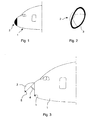
- FIG. 1 represents such a radome 2 fixed on the front tip of the fuselage 1 of an aircraft.
- FIG. 2 represents a perspective view of such a radome, in particular its perimeter 3 able to come into contact with the fuselage 1 of the aircraft.
- this radome makes it possible to protect a radar and is therefore made of a material permeable to electromagnetic waves, for example an electrically insulating composite material. Such a material is generally more flexible and more deformable than the fuselage structure on which this radome is fixed.
- the radome 2 In order to guarantee the best aerodynamic performance of the aircraft, the radome 2 must be fixed on the aircraft 1 on the one hand with games less than a predetermined value at the junction between the perimeter 3 of the radome and the fuselage 1 of the aircraft and on the other hand by avoiding misalignments between the surface of the radome and the surface of the fuselage, which would be sources of discontinuity in the flow of air on the surface of the aircraft, and consequently of turbulence which could reduce the aerodynamic performance of said aircraft.
- a radome 2 can be fixed on the fuselage 1 of an aircraft by using on the one hand jacks 4 making it possible to release said radome, for example during maintenance operations of the aircraft.
- a radar located at the front tip of the fuselage 1, and secondly locking means 5 which keep in place this radome on the fuselage during use of the aircraft.
- Such a fixing device generally gives satisfaction for nose radomes before small or medium-sized aircraft.
- said first fasteners allow centering of the radome on the fuselage of the aircraft while said second fasteners allow the radome to be positioned between said first fasteners, while maintaining a positioning freedom along an axis during the assembly of said seconds. fasteners.
- said single axis in which is ensured the positioning of the radome by each of said second fastenings is substantially perpendicular to the tangent to the perimeter of the radome at the point where the distance between on the one hand said perimeter of the radome able to come into contact with the fuselage and secondly the longitudinal axis of said attachment is minimal.
- the device according to the invention makes it possible to ensure a perfect outcropping of the outer surface of the radome with the outer surface of the fuselage, while at the same time making it possible to keep mounting clearances, at each of the second fastenings, according to a direction parallel to the tangent to the perimeter of the radome in contact with the fuselage at the point where the distance between firstly said perimeter of the radome in contact with the fuselage and secondly the longitudinal axis of said attachment is minimal.
- said plane substantially perpendicular to the longitudinal axis of each attachment is substantially perpendicular to the longitudinal axis of the aircraft.
- said first and second fasteners are accessible from inside said radome.
- these bindings do not require an external element on the surface of the radome or the fuselage, which could degrade the aerodynamic performance of the aircraft.
- said first and second fasteners each comprise a portion of convex shape integral with the radome, adapted to be engaged in a portion of concave shape integral with the fuselage of the aircraft.
- this embodiment is not exclusive and it is also possible to envisage a variant in which said first and second fasteners each comprise a portion of concave shape integral with the radome, adapted to be engaged in a portion of convex shape integral with the fuselage of the aircraft.
- said portion of convex shape, relative to the first fasteners is of substantially hemispherical shape.
- the convex shape portion, relative to the second fasteners is in turn substantially hemispherical shape, truncated by two planes substantially parallel to the longitudinal axis of the attachment and located on either side of this longitudinal axis. These two planes make it possible to define said single axis contained in a plane substantially perpendicular to the longitudinal axis of the second fixation considered and according to which said fixing ensures the positioning of the radome.
- This single axis is parallel to these two planes and perpendicular to the longitudinal axis of the considered fastener. Truncating this substantially hemispherical portion thus provides a mounting clearance during the insertion of said portion into the convex portion of the second fastener considered.
- said substantially hemispherical portion of the first and second fasteners is truncated in the portion opposite its base.
- each of the first and second fasteners is complementary to the substantially hemispherical convex shaped portion corresponding to the first fasteners.
- said first and second fasteners comprise a fitting integral with the hull of the radome.
- said first and second fasteners are screwed fasteners.
- each of the first and second fasteners is advantageously drilled along the longitudinal axis of the fastener considered so as to receive a screw for securing this portion of concave shape with the complementary convex portion.
- each of the first and second fasteners is advantageously pierced along the longitudinal axis of the fastener considered and threaded so as to be able to receive a screw for securing this convex part with the shaped part. complementary concave.
- each of the first fasteners is adapted to receive a guide rod adapted to cooperate with the concave portion of the fastener considered to guide the radome during the establishment of said radome on the fuselage.
- At least a portion of said first and / or second fasteners are made at least partially in at least one electrically conductive material and are electrically connected to a conductive element located on the outer surface of the radome.
- the number and the dimensioning of the electrically conductive fasteners are then advantageously provided to allow the flow of the currents due to the lightning impacts on the radome towards the fuselage of the aircraft.
- the invention also relates to an aircraft comprising a front nose radome characterized in that said radome is attached to the fuselage of the aircraft by means of such a fixing device.
- first fasteners 10 are disposed inside the radome, close to the perimeter 3 of the latter adapted to come into contact with the fuselage of the aircraft.
- these first fasteners are distributed, preferably substantially evenly, near said perimeter 3. In this way, they allow the centering of the radome 2 on the fuselage 1 of the aircraft.
- Second fasteners 12 are distributed substantially evenly, between said first fasteners 12, inside the radome, near said perimeter 3 thereof.
- thirteen second fasteners 12 are distributed between the first four fasteners 10.
- Said first and second fasteners each comprise a portion 14, 24 of convex shape integral with the radome 2.
- a portion 14 of convex shape corresponding to the first fasteners 10 is shown in Figures 5a, 5b and 5c.
- This portion 14 has a surface 20 of substantially hemispherical shape. The latter is truncated in the portion opposite its base, which thus has a flat portion 22.
- the base is extended by a part 19 of coaxial cylindrical shape of the longitudinal axis L of the considered fastener. This part 19 allows the centering of said portion 14 on a support secured to the radome 2.
- said base of the substantially hemispherical portion 20 has tapped holes 18 which allow the fixation part 14 on said support integral with the radome.
- this method of attachment is not exclusive and variants can be envisaged.
- the portion 19 of cylindrical shape is threaded so that it can be screwed into a threaded hole of said support integral with the radome, or be fixed on said support by means of a nut.
- the part 19 allows both the centering and the attachment of the portion 14 on said support.
- the portion 14 is pierced with a threaded hole 16 along the longitudinal axis L of the fastener considered.
- a convex shaped portion 24 corresponding to the second fasteners 12 is shown in Figures 6a, 6b and 6c.
- This portion 24 has a surface 30 of substantially hemispherical shape. The latter is truncated in the portion opposite to its base, which therefore has a flat portion 32. It is further truncated along two planes P1 and P2 substantially parallel to the longitudinal axis L of the binding considered and located on both sides. other than said longitudinal axis L. Said single axis of a plane substantially perpendicular to the longitudinal axis L of the attachment, according to which the second fixation considered ensures the positioning of the radome 2, is then parallel to the line BB shown in FIG. 6b .
- said single axis has an intersection with said longitudinal axis L.
- the base is extended by a portion 29 of coaxial cylindrical shape of the longitudinal axis L of the considered fastener.
- This portion 29 allows the centering of said portion 24 on a support secured to the radome 2.
- said base of the substantially hemispherical portion 30 comprises threaded holes 28 which allow the attachment of the portion 24 on said support integral with the radome.
- this method of attachment is not exclusive and variants can be envisaged.
- the portion 29 of cylindrical shape is threaded so that it can be screwed into a threaded hole of said support integral with the radome, or be fixed on said support by means of a nut.
- the part 29 allows both the centering and the fixing of the portion 24 on said support.
- the portion 24 is pierced with a threaded hole 26 along the longitudinal axis L of the fastener considered.
- the diameter of the flat face 32 of this convex portion is slightly less than the diameter of a flat face complementary to the concave portion 42 of the second fastener considered, on which the flat face bears when said second fastener is assembled.
- Said support secured to the radome 2 is preferably a fitting 54 shown in Figures 9a, 9b and 9c.
- This fitting comprises a base 58 adapted to be fixed on an inner surface of the radome 2. It also comprises a flat face 60 substantially perpendicular to the longitudinal axis L of the considered fixing. When the convex portions 14, 24 have a cylindrical portion 19, 29, this flat face 60 has a hole (not shown) coaxial with said longitudinal axis L and adapted to receive said cylindrical portion.
- Figure 10a is a sectional view of a radome 2 on which are fixed fittings 54 corresponding to first and second fastenings of said radome on the fuselage of an aircraft.
- the flat faces 60 of the various fittings 54 are oriented so that the longitudinal axes L of each of said fasteners (which are substantially perpendicular to said flat faces 60) are substantially parallel to each other. and to the longitudinal axis of the aircraft on which the radome 2 is to be fixed.
- the various fittings 54 may be of different geometric shapes to each other and adapted to the locations of the radome 2 to which are fixed said fittings.
- FIG. 10b shows in detail the two lower fittings of FIG. 10a, in position on the radome 2.
- Figures 7 and 8 represent indifferently a first or a second attachment 10, 12 according to the invention.
- a fitting 54 is fixed by its base 58 on the radome 2.
- a convex portion 14 (or 24) is fixed on the flat face 60 of this fitting.
- a stud 40 is fixed on a frame 50 of the fuselage 1 of the aircraft.
- This stud 40 has a concave portion 42 complementary to said convex portion 14 and a cylindrical portion 44 adapted to be engaged in a hole of said frame 50 of the fuselage, said hole being coaxial with the longitudinal axis of the fastener considered.
- said cylindrical portion 44 is threaded and a ring 46 is fixed on the frame 50.
- This bracket 46 comprises a tapped hole coaxial with the longitudinal axis of the considered fastener, apt to receive said cylindrical portion Threaded 44.
- This advantageously ensures the fixing of said bolt 40 on the frame 50 of the fuselage, as well as the adjustment in position of the concave portion 42 of said bolt 40 along the longitudinal axis L of the fastener.
- the stud 40 is pierced with a hole coaxial with the longitudinal axis of the fastener considered.
- This hole makes it possible to receive a screw 48, one end of which is capable of being engaged in the tapped hole 16, 26 of the convex part 14, 24. This screw thus makes it possible to secure said convex portion 14, 24 to the stud 40 and thus to the frame 50 of the fuselage 1.
- a seal 56 is fixed on the radome 2 near said perimeter 3 thereof. This seal comes into contact with the fuselage 1 of the aircraft so as to seal the volume inside the radome.
- the tapped hole 16 of the convex portion 14 of the first fasteners 10 can receive a cylindrical guide rod 52 having a threaded end adapted to be screwed into the tapped hole.
- the hole made in the stud 40, coaxial with the longitudinal axis L of the fastener is of diameter sufficiently greater than the diameter of this guide rod 52 to facilitate the insertion of this guide rod in this hole.
- the diameter of this hole may be chosen 2 to 3 times greater than the diameter of the guide rod 52.
- said diameter of the plane face 32 is chosen so that the second attachment considered has a slight clearance, radial with respect to the longitudinal axis L of this fixation, of a few tenths of a millimeter, preferably about five tenths of a millimeter.
- the radome 2 may comprise on its outer surface metal strips used to flow towards the fuselage 1 of the aircraft currents due to the impact of the lightning on this radome.
- the different parts 54, 14, 24, 40, 46, 48, 50 constituting at least some of the first and / or second fasteners 10, 12 are electrically conductive so that the fastener considered provides electrical continuity between the radome and the fuselage 1 of the aircraft.
- Said metal strips are electrically connected to electrically conductive fasteners 54, for example by means of screws passing through the wall of the radome 2.
- the number and dimensions of the electrically conductive fasteners are chosen to allow flow towards the fuselage. maximum currents due to the impacts of lightning on the radome 2.
- the various fasteners 10, 12 are all conductive.
- the average diameter of the substantially spherical portion 20, 30 convex portions 14, 24 is about 38 millimeters
- the distance between the planes P1 and P2 of the convex portions 24 of the second fasteners is about 24 millimeters
- the diameter of the screws 48 is about 9 millimeters.
Landscapes
- Engineering & Computer Science (AREA)
- Mechanical Engineering (AREA)
- Aviation & Aerospace Engineering (AREA)
- Details Of Aerials (AREA)
- Support Of Aerials (AREA)
- Connection Of Plates (AREA)
Applications Claiming Priority (1)
| Application Number | Priority Date | Filing Date | Title |
|---|---|---|---|
| FR0407090A FR2872127B1 (fr) | 2004-06-29 | 2004-06-29 | Dispositif et procede de fixation d'un radome d'aeronef |
Publications (2)
| Publication Number | Publication Date |
|---|---|
| EP1612139A1 true EP1612139A1 (de) | 2006-01-04 |
| EP1612139B1 EP1612139B1 (de) | 2008-02-20 |
Family
ID=34942674
Family Applications (1)
| Application Number | Title | Priority Date | Filing Date |
|---|---|---|---|
| EP05352013A Not-in-force EP1612139B1 (de) | 2004-06-29 | 2005-06-20 | Vorrichtung und Verfahren zur Befestigung eines Flugzeug-Radoms |
Country Status (6)
| Country | Link |
|---|---|
| US (1) | US7677498B2 (de) |
| EP (1) | EP1612139B1 (de) |
| AT (1) | ATE386682T1 (de) |
| CA (1) | CA2510908C (de) |
| DE (1) | DE602005004839T2 (de) |
| FR (1) | FR2872127B1 (de) |
Cited By (3)
| Publication number | Priority date | Publication date | Assignee | Title |
|---|---|---|---|---|
| WO2011030078A1 (fr) * | 2009-09-11 | 2011-03-17 | Airbus Operations (S.A.S) | Radôme et dispositif de fixation de ce radôme à un aéronef |
| FR2976909A1 (fr) * | 2011-06-27 | 2012-12-28 | Airbus Operations Sas | Procede d'ouverture d'un dome de protection, en particulier d'un radome, et radome equipe d'un pantographe de mise en oeuvre |
| EP2712019A1 (de) * | 2012-09-24 | 2014-03-26 | Alcatel- Lucent Shanghai Bell Co., Ltd | Vorrichtung zum Befestigen einer Antennenkuppel auf einem Parabolreflektor einer Antenne |
Families Citing this family (11)
| Publication number | Priority date | Publication date | Assignee | Title |
|---|---|---|---|---|
| US8314736B2 (en) * | 2008-03-31 | 2012-11-20 | Golba Llc | Determining the position of a mobile device using the characteristics of received signals and a reference database |
| US20080246632A1 (en) * | 2007-04-03 | 2008-10-09 | Embedded Control Systems | Aviation Rf Receiver Front End Multiplexing Method and Apparatus |
| FR2940959B1 (fr) * | 2009-01-15 | 2011-03-11 | Airbus France | Partie avant d'aeronef comportant une cloison concave separant une zone de radome non pressurisee et une zone pressurisee |
| KR101286234B1 (ko) | 2011-12-29 | 2013-07-15 | 한국항공우주산업 주식회사 | 항공기 동체 간극조절용 스터드 볼트 어셈블리 |
| US10189578B2 (en) * | 2013-06-12 | 2019-01-29 | The Boeing Company | Self-balancing pressure bulkhead |
| CN104512556A (zh) * | 2013-09-30 | 2015-04-15 | 哈尔滨飞机工业集团有限责任公司 | 飞机雷达罩四连杆开启机构 |
| US9564681B2 (en) * | 2013-11-11 | 2017-02-07 | Gogo Llc | Radome having localized areas of reduced radio signal attenuation |
| EP3635815B1 (de) | 2017-06-05 | 2022-06-01 | The Nordam Group LLC | Zugängliche radomanordnung |
| RU2706772C1 (ru) * | 2018-11-30 | 2019-11-20 | Российская Федерация, от имени которой выступает Министерство обороны Российской Федерации | Устройство установки радиопрозрачного обтекателя на корпус летательного аппарата |
| DE102019114149B3 (de) | 2019-05-27 | 2020-07-30 | Airbus Defence and Space GmbH | Verfahren zum Herstellen einer Elektronikanordnung, die gegen raue Umgebungsbedingungen geschützt ist, insbesondere für Luftfahrzeuge, Elektronikanordnung und Luftfahrzeug |
| CN112896544B (zh) * | 2021-02-04 | 2022-11-15 | 浙江大学 | 一种用于飞机旋罩支架的架外放置装置 |
Citations (5)
| Publication number | Priority date | Publication date | Assignee | Title |
|---|---|---|---|---|
| US2820499A (en) * | 1954-12-17 | 1958-01-21 | Mcdonnell Aircraft Corp | Floating, swivelling anchor nut |
| US3020946A (en) * | 1957-02-28 | 1962-02-13 | Elastic Stop Nut Corp | Anchor unit with spherical surface to permit angular movement |
| GB1092831A (en) * | 1965-01-08 | 1967-11-29 | Marconi Co Ltd | Improvements in or relating to containers |
| US3545146A (en) * | 1965-01-29 | 1970-12-08 | Northrop Corp | Ceramic-plastic radome |
| US5979831A (en) * | 1998-06-25 | 1999-11-09 | Mcdonnell Douglas Corporation | System and method for attaching a structural component to an aerospace vehicle |
Family Cites Families (11)
| Publication number | Priority date | Publication date | Assignee | Title |
|---|---|---|---|---|
| US1467824A (en) * | 1922-06-24 | 1923-09-11 | David E Ahlers | Bolt and nut lock |
| US2510110A (en) * | 1945-03-30 | 1950-06-06 | Clarence N Hickman | Step-motor rocket projectile |
| US2755216A (en) * | 1952-08-16 | 1956-07-17 | Douglas Aircraft Co Inc | Process for forming a multi-ducted shell |
| US3188961A (en) * | 1961-05-25 | 1965-06-15 | Bendix Corp | Means for cooling structures that are periodically heated to elevated temperatures |
| US4520364A (en) * | 1983-04-19 | 1985-05-28 | The United States Of America As Represented By The Secretary Of The Air Force | Attachment method-ceramic radome to metal body |
| US4760493A (en) * | 1985-09-30 | 1988-07-26 | The Boeing Company | Lightning protection system for composite material aircraft structures |
| FR2621554B1 (fr) * | 1987-10-07 | 1990-01-05 | Snecma | Capot d'entree non tournant de turboreacteur a fixation centrale et turboreacteur ainsi equipe |
| IT1248615B (it) * | 1990-05-08 | 1995-01-21 | Fiat Auto Spa | Dispositivo di collegamento di parti meccaniche alla scocca di un autoveicolo |
| FR2729117B1 (fr) * | 1995-01-10 | 1997-04-04 | Aerospatiale | Procede de pilotage d'un engin et engin permettant la mise en oeuvre du procede |
| US7377469B2 (en) * | 2001-09-05 | 2008-05-27 | Gabe Cherian | Heat shield |
| US6796529B1 (en) * | 2003-07-08 | 2004-09-28 | Avibank.Mfg., Inc. | Aircraft strut |
-
2004
- 2004-06-29 FR FR0407090A patent/FR2872127B1/fr not_active Expired - Fee Related
-
2005
- 2005-06-20 DE DE602005004839T patent/DE602005004839T2/de active Active
- 2005-06-20 EP EP05352013A patent/EP1612139B1/de not_active Not-in-force
- 2005-06-20 AT AT05352013T patent/ATE386682T1/de not_active IP Right Cessation
- 2005-06-21 US US11/156,580 patent/US7677498B2/en not_active Expired - Fee Related
- 2005-06-23 CA CA2510908A patent/CA2510908C/en not_active Expired - Fee Related
Patent Citations (5)
| Publication number | Priority date | Publication date | Assignee | Title |
|---|---|---|---|---|
| US2820499A (en) * | 1954-12-17 | 1958-01-21 | Mcdonnell Aircraft Corp | Floating, swivelling anchor nut |
| US3020946A (en) * | 1957-02-28 | 1962-02-13 | Elastic Stop Nut Corp | Anchor unit with spherical surface to permit angular movement |
| GB1092831A (en) * | 1965-01-08 | 1967-11-29 | Marconi Co Ltd | Improvements in or relating to containers |
| US3545146A (en) * | 1965-01-29 | 1970-12-08 | Northrop Corp | Ceramic-plastic radome |
| US5979831A (en) * | 1998-06-25 | 1999-11-09 | Mcdonnell Douglas Corporation | System and method for attaching a structural component to an aerospace vehicle |
Cited By (8)
| Publication number | Priority date | Publication date | Assignee | Title |
|---|---|---|---|---|
| WO2011030078A1 (fr) * | 2009-09-11 | 2011-03-17 | Airbus Operations (S.A.S) | Radôme et dispositif de fixation de ce radôme à un aéronef |
| FR2950199A1 (fr) * | 2009-09-11 | 2011-03-18 | Airbus Operations Sas | Radome et dispositif de fixation de ce radome a un aeronef |
| CN102576931A (zh) * | 2009-09-11 | 2012-07-11 | 空中客车运营简化股份公司 | 雷达罩以及用于将所述雷达罩附连到飞行器的装置 |
| US8816916B2 (en) | 2009-09-11 | 2014-08-26 | Airbus Operations S.A.S. | Radome and device for attaching said radome to an aircraft |
| CN102576931B (zh) * | 2009-09-11 | 2015-06-03 | 空中客车运营简化股份公司 | 雷达罩以及用于将所述雷达罩附连到飞行器的装置 |
| FR2976909A1 (fr) * | 2011-06-27 | 2012-12-28 | Airbus Operations Sas | Procede d'ouverture d'un dome de protection, en particulier d'un radome, et radome equipe d'un pantographe de mise en oeuvre |
| WO2013001224A1 (fr) * | 2011-06-27 | 2013-01-03 | Airbus Operations Sas | Procédé d'ouverture d'un dôme de protection, en particulier d'un radome, et radome équipé d'un pantographe de mise en œuvre |
| EP2712019A1 (de) * | 2012-09-24 | 2014-03-26 | Alcatel- Lucent Shanghai Bell Co., Ltd | Vorrichtung zum Befestigen einer Antennenkuppel auf einem Parabolreflektor einer Antenne |
Also Published As
| Publication number | Publication date |
|---|---|
| DE602005004839D1 (de) | 2008-04-03 |
| DE602005004839T2 (de) | 2009-02-12 |
| FR2872127B1 (fr) | 2006-08-11 |
| EP1612139B1 (de) | 2008-02-20 |
| ATE386682T1 (de) | 2008-03-15 |
| US20070045467A1 (en) | 2007-03-01 |
| FR2872127A1 (fr) | 2005-12-30 |
| US7677498B2 (en) | 2010-03-16 |
| CA2510908A1 (en) | 2005-12-29 |
| CA2510908C (en) | 2013-02-12 |
Similar Documents
| Publication | Publication Date | Title |
|---|---|---|
| EP1612139B1 (de) | Vorrichtung und Verfahren zur Befestigung eines Flugzeug-Radoms | |
| EP1355120B1 (de) | Vorrichtung zur provisorischen Verbindung und zum pyrotechnischen Trennen von zwei Elementen, ohne Bruch | |
| WO2011055100A2 (fr) | Support pour maintenir en position des objets allongés par rapport à une structure | |
| WO2014016303A1 (fr) | Système de fixation d'une pile thermique dans une section d'alimentation d'un engin sous marin | |
| EP2546614B1 (de) | Sensor- oder Detektorvorrichtung mit einem perfektionierten Kabelführungsstöpsel | |
| FR2909153A1 (fr) | Dispositif pour la fixation d'un element | |
| FR3018773A1 (fr) | Dispositif de support | |
| EP1361411A2 (de) | Vorrichtung mit bewegbarem Element, zur provisorischen Verbindung und zum pyrotechnischen Abtrennen von zwei Einheiten | |
| CA2994641C (fr) | Satellite artificiel | |
| EP4148254A1 (de) | Baugruppe für eine luftfahrzeuggondel, die eine halteplatte, einen wärmeschutz und ein befestigungssystem umfasst | |
| BE1012055A3 (fr) | Dispositif de fixation par ecrou. | |
| EP2656002B1 (de) | Pyrotechnisches bruchstück mit reversibler detonation | |
| EP2289124A2 (de) | Antennensystemanordnung mit eingebauter selbsttragender antenne und entsprechendes antennensystem | |
| EP1376045A1 (de) | Vorrichtung zum Adaptieren eines aus einem Rohr abzuschiessenden Projektils | |
| FR2650387A1 (fr) | Dispositif de fixation d'elements de blindage sur un vehicule | |
| WO2010063927A1 (fr) | Ensemble moteur pour aéronef comprenant une structure rigide modulaire de mât d'accrochage | |
| FR3068091B1 (fr) | Systeme de fixation a tenons pourvus d'appendices decales angulairement | |
| EP2683028A1 (de) | Antennensystem | |
| FR2496349A1 (fr) | Dispositif pour le support d'objets allonges tels que cables, faisceaux de cables ou analogues et installations comportant de tels dispositifs | |
| FR2903466A1 (fr) | Systeme d'ecrou flottant | |
| FR3073021B1 (fr) | Ensemble comportant un panneau et un systeme de fixation | |
| EP1695024B1 (de) | Mit trennbaren teilen versehene pyrotechnische verbindung und mindestens solch eine verbindung umfassende startvorrichtung | |
| FR3065437A1 (fr) | Systeme de prise de parc de conditionnement d'air pour la connexion d'un generateur d'air a un aeronef | |
| FR2562170A1 (fr) | Dispositif pour l'assemblage d'elements modulaires et elements modulaires relies par un tel dispositif | |
| FR3145785A1 (fr) | Dispositif de fixation à fonctions de découplage et anti-projection |
Legal Events
| Date | Code | Title | Description |
|---|---|---|---|
| PUAI | Public reference made under article 153(3) epc to a published international application that has entered the european phase |
Free format text: ORIGINAL CODE: 0009012 |
|
| AK | Designated contracting states |
Kind code of ref document: A1 Designated state(s): AT BE BG CH CY CZ DE DK EE ES FI FR GB GR HU IE IS IT LI LT LU MC NL PL PT RO SE SI SK TR |
|
| AX | Request for extension of the european patent |
Extension state: AL BA HR LV MK YU |
|
| 17P | Request for examination filed |
Effective date: 20060704 |
|
| AKX | Designation fees paid |
Designated state(s): AT BE BG CH CY CZ DE DK EE ES FI FR GB GR HU IE IS IT LI LT LU MC NL PL PT RO SE SI SK TR |
|
| 17Q | First examination report despatched |
Effective date: 20060908 |
|
| GRAP | Despatch of communication of intention to grant a patent |
Free format text: ORIGINAL CODE: EPIDOSNIGR1 |
|
| GRAS | Grant fee paid |
Free format text: ORIGINAL CODE: EPIDOSNIGR3 |
|
| GRAA | (expected) grant |
Free format text: ORIGINAL CODE: 0009210 |
|
| AK | Designated contracting states |
Kind code of ref document: B1 Designated state(s): AT BE BG CH CY CZ DE DK EE ES FI FR GB GR HU IE IS IT LI LT LU MC NL PL PT RO SE SI SK TR |
|
| REG | Reference to a national code |
Ref country code: GB Ref legal event code: FG4D Free format text: NOT ENGLISH |
|
| RIN1 | Information on inventor provided before grant (corrected) |
Inventor name: BELLET, DANIEL Inventor name: JEANNEAU, CHARLOTTE Inventor name: RIGAL, HENRI Inventor name: FRONT, EMMANUEL Inventor name: ROQUES, JEAN-CLAUDE Inventor name: GILABERT, ROLLAND |
|
| REG | Reference to a national code |
Ref country code: CH Ref legal event code: EP |
|
| REG | Reference to a national code |
Ref country code: IE Ref legal event code: FG4D Free format text: LANGUAGE OF EP DOCUMENT: FRENCH |
|
| REF | Corresponds to: |
Ref document number: 602005004839 Country of ref document: DE Date of ref document: 20080403 Kind code of ref document: P |
|
| GBT | Gb: translation of ep patent filed (gb section 77(6)(a)/1977) |
Effective date: 20080403 |
|
| REG | Reference to a national code |
Ref country code: SE Ref legal event code: TRGR |
|
| PG25 | Lapsed in a contracting state [announced via postgrant information from national office to epo] |
Ref country code: IS Free format text: LAPSE BECAUSE OF FAILURE TO SUBMIT A TRANSLATION OF THE DESCRIPTION OR TO PAY THE FEE WITHIN THE PRESCRIBED TIME-LIMIT Effective date: 20080620 Ref country code: FI Free format text: LAPSE BECAUSE OF FAILURE TO SUBMIT A TRANSLATION OF THE DESCRIPTION OR TO PAY THE FEE WITHIN THE PRESCRIBED TIME-LIMIT Effective date: 20080220 Ref country code: ES Free format text: LAPSE BECAUSE OF FAILURE TO SUBMIT A TRANSLATION OF THE DESCRIPTION OR TO PAY THE FEE WITHIN THE PRESCRIBED TIME-LIMIT Effective date: 20080531 |
|
| NLV1 | Nl: lapsed or annulled due to failure to fulfill the requirements of art. 29p and 29m of the patents act | ||
| PG25 | Lapsed in a contracting state [announced via postgrant information from national office to epo] |
Ref country code: AT Free format text: LAPSE BECAUSE OF FAILURE TO SUBMIT A TRANSLATION OF THE DESCRIPTION OR TO PAY THE FEE WITHIN THE PRESCRIBED TIME-LIMIT Effective date: 20080220 |
|
| PG25 | Lapsed in a contracting state [announced via postgrant information from national office to epo] |
Ref country code: PL Free format text: LAPSE BECAUSE OF FAILURE TO SUBMIT A TRANSLATION OF THE DESCRIPTION OR TO PAY THE FEE WITHIN THE PRESCRIBED TIME-LIMIT Effective date: 20080220 Ref country code: SI Free format text: LAPSE BECAUSE OF FAILURE TO SUBMIT A TRANSLATION OF THE DESCRIPTION OR TO PAY THE FEE WITHIN THE PRESCRIBED TIME-LIMIT Effective date: 20080220 |
|
| REG | Reference to a national code |
Ref country code: IE Ref legal event code: FD4D |
|
| PG25 | Lapsed in a contracting state [announced via postgrant information from national office to epo] |
Ref country code: PT Free format text: LAPSE BECAUSE OF FAILURE TO SUBMIT A TRANSLATION OF THE DESCRIPTION OR TO PAY THE FEE WITHIN THE PRESCRIBED TIME-LIMIT Effective date: 20080721 Ref country code: NL Free format text: LAPSE BECAUSE OF FAILURE TO SUBMIT A TRANSLATION OF THE DESCRIPTION OR TO PAY THE FEE WITHIN THE PRESCRIBED TIME-LIMIT Effective date: 20080220 Ref country code: SK Free format text: LAPSE BECAUSE OF FAILURE TO SUBMIT A TRANSLATION OF THE DESCRIPTION OR TO PAY THE FEE WITHIN THE PRESCRIBED TIME-LIMIT Effective date: 20080220 Ref country code: DK Free format text: LAPSE BECAUSE OF FAILURE TO SUBMIT A TRANSLATION OF THE DESCRIPTION OR TO PAY THE FEE WITHIN THE PRESCRIBED TIME-LIMIT Effective date: 20080220 Ref country code: CZ Free format text: LAPSE BECAUSE OF FAILURE TO SUBMIT A TRANSLATION OF THE DESCRIPTION OR TO PAY THE FEE WITHIN THE PRESCRIBED TIME-LIMIT Effective date: 20080220 Ref country code: IE Free format text: LAPSE BECAUSE OF FAILURE TO SUBMIT A TRANSLATION OF THE DESCRIPTION OR TO PAY THE FEE WITHIN THE PRESCRIBED TIME-LIMIT Effective date: 20080220 |
|
| PG25 | Lapsed in a contracting state [announced via postgrant information from national office to epo] |
Ref country code: RO Free format text: LAPSE BECAUSE OF FAILURE TO SUBMIT A TRANSLATION OF THE DESCRIPTION OR TO PAY THE FEE WITHIN THE PRESCRIBED TIME-LIMIT Effective date: 20080220 |
|
| PLBE | No opposition filed within time limit |
Free format text: ORIGINAL CODE: 0009261 |
|
| STAA | Information on the status of an ep patent application or granted ep patent |
Free format text: STATUS: NO OPPOSITION FILED WITHIN TIME LIMIT |
|
| BERE | Be: lapsed |
Owner name: AIRBUS FRANCE Effective date: 20080630 |
|
| 26N | No opposition filed |
Effective date: 20081121 |
|
| PG25 | Lapsed in a contracting state [announced via postgrant information from national office to epo] |
Ref country code: MC Free format text: LAPSE BECAUSE OF NON-PAYMENT OF DUE FEES Effective date: 20080630 Ref country code: LT Free format text: LAPSE BECAUSE OF FAILURE TO SUBMIT A TRANSLATION OF THE DESCRIPTION OR TO PAY THE FEE WITHIN THE PRESCRIBED TIME-LIMIT Effective date: 20080220 |
|
| PG25 | Lapsed in a contracting state [announced via postgrant information from national office to epo] |
Ref country code: BE Free format text: LAPSE BECAUSE OF NON-PAYMENT OF DUE FEES Effective date: 20080630 |
|
| PG25 | Lapsed in a contracting state [announced via postgrant information from national office to epo] |
Ref country code: EE Free format text: LAPSE BECAUSE OF FAILURE TO SUBMIT A TRANSLATION OF THE DESCRIPTION OR TO PAY THE FEE WITHIN THE PRESCRIBED TIME-LIMIT Effective date: 20080220 Ref country code: BG Free format text: LAPSE BECAUSE OF FAILURE TO SUBMIT A TRANSLATION OF THE DESCRIPTION OR TO PAY THE FEE WITHIN THE PRESCRIBED TIME-LIMIT Effective date: 20080520 |
|
| PG25 | Lapsed in a contracting state [announced via postgrant information from national office to epo] |
Ref country code: CY Free format text: LAPSE BECAUSE OF FAILURE TO SUBMIT A TRANSLATION OF THE DESCRIPTION OR TO PAY THE FEE WITHIN THE PRESCRIBED TIME-LIMIT Effective date: 20080220 |
|
| PGFP | Annual fee paid to national office [announced via postgrant information from national office to epo] |
Ref country code: SE Payment date: 20090612 Year of fee payment: 5 |
|
| REG | Reference to a national code |
Ref country code: CH Ref legal event code: PL |
|
| PG25 | Lapsed in a contracting state [announced via postgrant information from national office to epo] |
Ref country code: LI Free format text: LAPSE BECAUSE OF NON-PAYMENT OF DUE FEES Effective date: 20090630 Ref country code: CH Free format text: LAPSE BECAUSE OF NON-PAYMENT OF DUE FEES Effective date: 20090630 |
|
| PG25 | Lapsed in a contracting state [announced via postgrant information from national office to epo] |
Ref country code: HU Free format text: LAPSE BECAUSE OF FAILURE TO SUBMIT A TRANSLATION OF THE DESCRIPTION OR TO PAY THE FEE WITHIN THE PRESCRIBED TIME-LIMIT Effective date: 20080821 Ref country code: LU Free format text: LAPSE BECAUSE OF NON-PAYMENT OF DUE FEES Effective date: 20080620 |
|
| PG25 | Lapsed in a contracting state [announced via postgrant information from national office to epo] |
Ref country code: TR Free format text: LAPSE BECAUSE OF FAILURE TO SUBMIT A TRANSLATION OF THE DESCRIPTION OR TO PAY THE FEE WITHIN THE PRESCRIBED TIME-LIMIT Effective date: 20080220 |
|
| PG25 | Lapsed in a contracting state [announced via postgrant information from national office to epo] |
Ref country code: GR Free format text: LAPSE BECAUSE OF FAILURE TO SUBMIT A TRANSLATION OF THE DESCRIPTION OR TO PAY THE FEE WITHIN THE PRESCRIBED TIME-LIMIT Effective date: 20080521 |
|
| EUG | Se: european patent has lapsed | ||
| REG | Reference to a national code |
Ref country code: GB Ref legal event code: 732E Free format text: REGISTERED BETWEEN 20110721 AND 20110727 |
|
| REG | Reference to a national code |
Ref country code: FR Ref legal event code: CD Owner name: AIRBUS HOLDING, FR Effective date: 20110916 Ref country code: FR Ref legal event code: CA Effective date: 20110916 Ref country code: FR Ref legal event code: TP Owner name: AIRBUS HOLDING, FR Effective date: 20110913 Ref country code: FR Ref legal event code: CJ Effective date: 20110916 |
|
| REG | Reference to a national code |
Ref country code: DE Ref legal event code: R081 Ref document number: 602005004839 Country of ref document: DE Owner name: AIRBUS OPERATIONS SAS, FR Free format text: FORMER OWNER: AIRBUS FRANCE, TOULOUSE, FR Effective date: 20120326 |
|
| PG25 | Lapsed in a contracting state [announced via postgrant information from national office to epo] |
Ref country code: SE Free format text: LAPSE BECAUSE OF NON-PAYMENT OF DUE FEES Effective date: 20100621 |
|
| REG | Reference to a national code |
Ref country code: FR Ref legal event code: PLFP Year of fee payment: 12 |
|
| REG | Reference to a national code |
Ref country code: FR Ref legal event code: PLFP Year of fee payment: 13 |
|
| PGFP | Annual fee paid to national office [announced via postgrant information from national office to epo] |
Ref country code: IT Payment date: 20170622 Year of fee payment: 13 |
|
| REG | Reference to a national code |
Ref country code: FR Ref legal event code: PLFP Year of fee payment: 14 |
|
| PG25 | Lapsed in a contracting state [announced via postgrant information from national office to epo] |
Ref country code: IT Free format text: LAPSE BECAUSE OF NON-PAYMENT OF DUE FEES Effective date: 20180620 |
|
| PGFP | Annual fee paid to national office [announced via postgrant information from national office to epo] |
Ref country code: DE Payment date: 20190619 Year of fee payment: 15 |
|
| PGFP | Annual fee paid to national office [announced via postgrant information from national office to epo] |
Ref country code: FR Payment date: 20190619 Year of fee payment: 15 |
|
| PGFP | Annual fee paid to national office [announced via postgrant information from national office to epo] |
Ref country code: GB Payment date: 20190619 Year of fee payment: 15 |
|
| REG | Reference to a national code |
Ref country code: DE Ref legal event code: R119 Ref document number: 602005004839 Country of ref document: DE |
|
| GBPC | Gb: european patent ceased through non-payment of renewal fee |
Effective date: 20200620 |
|
| PG25 | Lapsed in a contracting state [announced via postgrant information from national office to epo] |
Ref country code: FR Free format text: LAPSE BECAUSE OF NON-PAYMENT OF DUE FEES Effective date: 20200630 Ref country code: GB Free format text: LAPSE BECAUSE OF NON-PAYMENT OF DUE FEES Effective date: 20200620 |
|
| PG25 | Lapsed in a contracting state [announced via postgrant information from national office to epo] |
Ref country code: DE Free format text: LAPSE BECAUSE OF NON-PAYMENT OF DUE FEES Effective date: 20210101 |