EP1610592B1 - Antriebsvorrichtung bei einem Mikrowellenofen versehen mit einem abnehmbaren Radträger - Google Patents
Antriebsvorrichtung bei einem Mikrowellenofen versehen mit einem abnehmbaren Radträger Download PDFInfo
- Publication number
- EP1610592B1 EP1610592B1 EP05013539A EP05013539A EP1610592B1 EP 1610592 B1 EP1610592 B1 EP 1610592B1 EP 05013539 A EP05013539 A EP 05013539A EP 05013539 A EP05013539 A EP 05013539A EP 1610592 B1 EP1610592 B1 EP 1610592B1
- Authority
- EP
- European Patent Office
- Prior art keywords
- microwave oven
- wheels
- bases
- rotating plate
- cavity
- Prior art date
- Legal status (The legal status is an assumption and is not a legal conclusion. Google has not performed a legal analysis and makes no representation as to the accuracy of the status listed.)
- Expired - Lifetime
Links
Images


Classifications
-
- H—ELECTRICITY
- H05—ELECTRIC TECHNIQUES NOT OTHERWISE PROVIDED FOR
- H05B—ELECTRIC HEATING; ELECTRIC LIGHT SOURCES NOT OTHERWISE PROVIDED FOR; CIRCUIT ARRANGEMENTS FOR ELECTRIC LIGHT SOURCES, IN GENERAL
- H05B6/00—Heating by electric, magnetic or electromagnetic fields
- H05B6/64—Heating using microwaves
- H05B6/6408—Supports or covers specially adapted for use in microwave heating apparatus
- H05B6/6411—Supports or covers specially adapted for use in microwave heating apparatus the supports being rotated
Definitions
- the present invention relates to a device for driving the turntable of a microwave oven comprising a means providing a rotational torque to the turntable, at least three wheels on which the turntable is placed and a wheel support removable member comprising the axes of rotation of said wheels, said axes being oriented radially relative to the plate.
- Known microwave ovens are generally provided with a turntable for receiving a container or the like containing the food to be heated.
- a turntable for receiving a container or the like containing the food to be heated.
- There are mainly two drive modes of this platform which is generally based on wheels connected to a wheel support.
- the torque supplied by a motor is transmitted directly to the plate.
- the plate then drives the wheels on which it rests and rolls in its movement.
- the torque supplied by a motor is transmitted to the wheel support which, by means of the wheels, rests and rolls on the bottom of the cavity of the microwave oven.
- the wheel support which, by means of the wheels, rests and rolls on the bottom of the cavity of the microwave oven.
- the platform rests directly on the wheel support and has a movement identical to that of said support.
- the plate rests on the wheels which rolling on said plate drive it in rotation at a speed twice as high as that of the wheel support.
- An additional constraint related to the second mode is that of having to position the wheel support in a particular direction, that is to say on the right face, and to position it so as to be able to couple it correctly to the means providing a torque. rotation to the turntable, by facing two flats or particular forms of drive.
- US4590351 discloses a removable turntable having its own drive system to accommodate fixed hearth microwave ovens.
- Three wheels are mounted on the periphery of the base of the tray in recessed areas. The wheels hold the tray in place and let it rotate.
- the object of the invention is to provide a wheel support which is positioned naturally whatever the direction and the angular position in which it is placed on the bottom of the cavity of the microwave oven.
- the invention proposes to use a drive such as the first mode described above, namely that the torque supplied by a motor is transmitted directly to the plate, the latter then driving in its movement the wheels on which it rests and rolled.
- the present invention relates to a device for driving the turntable of a microwave oven comprising means providing a rotational torque to the turntable, at least three wheels on which the turntable is placed and a support removable wheel comprising the axes of rotation of said wheels, said axes being oriented radially relative to the plate.
- the drive device of the turntable further comprises bases mounted on the removable wheel support, said bases resting on the bottom, of the cavity of the microwave oven, said bases ensuring the immobility of the removable wheel support relative to said cavity, and the bases mounted on the removable wheel support are mounted free to rotate about the axes of said wheels, the center of gravity of said bases being positioned so that the part of said bases revealing the wheels is always on the top regardless of the orientation of the removable wheel support.
- the removable wheel carrier whatever the direction in which the removable wheel carrier is inserted into the cavity of the microwave oven, it will always rest on the bases and present the wheels ready to receive the turntable.
- the invention thus eliminates malfunctions related to the presence of foreign bodies between the wheels and the ferrule.
- an interesting consequence of the invention is that it eliminates malfunctions related to a bad positioning of the wheel support.
- Another interesting consequence of this device is that it facilitates the cleaning of the cavity of the microwave oven since its removal and its introduction are easy.
- the bases are positioned in a circular stamp formed in the bottom of the cavity of the microwave oven.
- the diameter of the circular stamping made in the bottom of the cavity of the microwave oven is identical to that of the specific circular tread present on the standard rotating plates and on which roll the wheels 5.
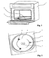
- FIG. 1 there is shown a perspective view of a microwave oven according to the invention.
- many components such as the furnace heating or ventilation means or its lighting are not shown or described here because they do not differ from devices well known to those skilled in the art and present on the current furnaces.
- the driving device comprises a means 7 providing a rotational torque to the turntable which in its inner part does not differ from the known devices and in its upper part engages with lugs located under the turntable 2 to ensure its training, so also known. It also comprises a removable wheel support 4 comprising the rotation axes 4 'of the wheels 5 on which the turntable 2 is placed. Said rotation axes 4 'are oriented radially with respect to the turntable 2.
- the drive device finally comprises bases 6 mounted on the removable wheel support 4, said bases 6 resting on the bottom 3 of the cavity of the microwave oven and ensuring the immobility of the removable wheel support 4 with respect to said cavity.
- These bases 6, mounted on the removable wheel support 4, are mounted free to rotate about the axes 4 'of said wheels 5, the center of gravity of said bases 6 being positioned so that the portion of said bases 6 revealing the wheels 5 is always on the top, regardless of the orientation of the removable wheel support 4.
- FIG 3 there is shown a sectional view of the drive device of the turntable 2 according to the invention. This view is based on the elements presented in the perspective view of the figure 1 .
- the bases 6 are housed in a circular stamp formed in the bottom 3 of the cavity of the microwave oven 1. This stamping is not essential but facilitates the positioning of the removable wheel support 4. In fact, the bases 6 coming to center naturally in this pressed, the positioning of the removable wheel support 4 is ensured.
- FIG. 4 a detail view of a wheel 5 of the device and of the base 6 associated with it is shown. There is also a part of the removable wheel support 4 and a wheel axis 4 'around which a base 6 is free to rotate.
- the removable wheel support 4 is metal and in the form of a circle on which are reported, for example by welding, the axes 4 '. But any other form could be envisaged such that a star having as many branches as wheels 5.
- the wheels 5 there must be at least three to provide a flat support for the turntable 2. It is possible to envisage more, but this has at least two disadvantages: a higher cost and risks of hyperstatism.
- the wheels 5 are made of Teflon to reduce friction and it is also possible to provide on the turntable 2 a tread (not shown) which is on the contact zone between the wheels 5 and the turntable 2.
- the wheels 5 are mounted on a groove of the axis 4 'whose diameter is smaller than that of the rest of the axis 4'. They are thus immobilized axially, but can rotate freely.
- the bases may be of any shape provided that they are mounted free to rotate about the axes 4 'of the wheels 5 and that their center of gravity is positioned opposite to the axis 4 ', the part of the wheels 5 they let appear.
- the bases 6 of the example illustrating the invention have a shape forming part of a parallelepiped.
- One of the faces, denominated superior in the following lines, of this parallelepiped is left open in order to let the wheel 5 which is housed inside the bases 6 pass.
- the side faces parallel to the two inner walls are also provided with notches.
- notches are designed so that the axis 4 'can not come out once inserted and that the only movement left to him is the rotation about the axis 4'.
- the angles between the lateral faces, parallel to the two inner walls, and the bottom face, opposite to the open face, are Lronques. This allows the base 6 to better adapt to the shape of the circular stamping made in the bottom 3 of the cavity of the microwave oven 1.
- the amount of material present above the zone of passage of the axis 4 ' is limited to the minimum necessary to position the center of gravity of the base 6 as low as possible, that is to say the further away from the open top.
- the natural position of the base will always face upwards, that is to say in the operating position, without the user having to choose a particular orientation for the removable wheel support 4.
- the invention responds to the concern of producing a drive device for a turntable microwave oven having the following advantages: a reduction of problems of jerk and slip related to the presence of foreign bodies between the wheels and the ferrule, a great ease of disassembly and ease of positioning thanks to its reversibility and ability to self-center.
Landscapes
- Physics & Mathematics (AREA)
- Electromagnetism (AREA)
- Electric Ovens (AREA)
- Constitution Of High-Frequency Heating (AREA)
- Handcart (AREA)
- Packaging Of Annular Or Rod-Shaped Articles, Wearing Apparel, Cassettes, Or The Like (AREA)
Claims (6)
- Vorrichtung zum Antrieb des Drehtellers (2) eines Mikrowellenherds (1), umfassend ein Mittel (7), welches dem Drehteller (2) ein Drehmoment verleiht, mindestens drei Rollen (5), auf welchen der Drehteller (2) aufliegt, und einen abnehmbaren Rollenträger (4), welcher die Drehachsen (4') der besagten Rollen (5) umfasst, wobei die besagten Achsen (4') radial zum Teller (2) ausgerichtet sind,
dadurch gekennzeichnet, dass sie weiterhin auf dem abnehmbaren Rollenträger (4) montierte Sockel (6) umfasst, wobei die besagten Sockel (6) auf dem Boden (3) des Garraums des Mikrowellenherds (1) aufliegen, wobei die besagten Sockel die Immobilität des abnehmbaren Rollenträgers (4) in Bezug auf den besagten Garraum gewährleisten, und dadurch, dass die auf dem abnehmbaren Rollenträger (4) montierten Sockel (6) frei drehend um die Achsen (4') der besagten Rollen (5) montiert sind, wobei der Schwerpunkt der besagten Sockel (6) derart positioniert ist, dass sich der Teil der besagten Sockel (6), auf welchem die Rollen (5) sichtbar sind, immer oben befindet, ungeachtet der Ausrichtung des abnehmbaren Rollenträgers (4). - Vorrichtung zum Antrieb des Drehtellers eines Mikrowellenherds nach Anspruch 1,
dadurch gekennzeichnet, dass die besagten Sockel (6) dazu ausgelegt sind, sich in einer im Boden (3) des Garraums des Mikrowellenherds (1) eingelassenen kreisförmigen Vertiefung zu positionieren. - Vorrichtung zum Antrieb des Drehtellers eines Mikrowellenherds nach Anspruch 2,
dadurch gekennzeichnet, dass der Durchmesser der im Boden (3) des Garraums des Mikrowellenherds (1) eingelassenen kreisförmigen Vertiefung mit dem Durchmesser der auf den Standard-Drehtellern vorhandenen spezifischen kreisförmigen Lauffläche, auf welcher sich die Rollen (5) bewegen, identisch ist. - Vorrichtung zum Antrieb des Drehtellers eines Mikrowellenherds nach einem der vorstehenden Ansprüche,
dadurch gekennzeichnet, dass die Rollen (5) auf einer Rille der Achse (4') montiert sind. - Vorrichtung zum Antrieb des Drehtellers eines Mikrowellenherds nach einem der vorstehenden Ansprüche,
dadurch gekennzeichnet, dass die Sockel (6) eine Form aufweisen, welche sich in ein Parallelepiped einschreibt. - Vorrichtung zum Antrieb des Drehtellers eines Mikrowellenherds nach einem der vorstehenden Ansprüche,
dadurch gekennzeichnet, dass die Winkel zwischen den Seitenflächen und der der offenen Seite des Sockels (6) gegenüberliegenden Seite abgestumpft sind.
Priority Applications (1)
| Application Number | Priority Date | Filing Date | Title |
|---|---|---|---|
| PL05013539T PL1610592T3 (pl) | 2004-06-25 | 2005-06-23 | Urządzenie do napędzania obrotowej płyty kuchenki mikrofalowej wyposażonej w zdejmowalną podporę kółek |
Applications Claiming Priority (2)
| Application Number | Priority Date | Filing Date | Title |
|---|---|---|---|
| FR0406965 | 2004-06-25 | ||
| FR0406965A FR2872259B1 (fr) | 2004-06-25 | 2004-06-25 | Dispositif d'entrainement du plateau tournant d'un four a micro-ondes muni d'un support de roues amovible |
Publications (3)
| Publication Number | Publication Date |
|---|---|
| EP1610592A2 EP1610592A2 (de) | 2005-12-28 |
| EP1610592A3 EP1610592A3 (de) | 2006-02-01 |
| EP1610592B1 true EP1610592B1 (de) | 2010-01-06 |
Family
ID=34945661
Family Applications (1)
| Application Number | Title | Priority Date | Filing Date |
|---|---|---|---|
| EP05013539A Expired - Lifetime EP1610592B1 (de) | 2004-06-25 | 2005-06-23 | Antriebsvorrichtung bei einem Mikrowellenofen versehen mit einem abnehmbaren Radträger |
Country Status (6)
| Country | Link |
|---|---|
| EP (1) | EP1610592B1 (de) |
| AT (1) | ATE454805T1 (de) |
| DE (1) | DE602005018714D1 (de) |
| ES (1) | ES2339121T3 (de) |
| FR (1) | FR2872259B1 (de) |
| PL (1) | PL1610592T3 (de) |
Families Citing this family (2)
| Publication number | Priority date | Publication date | Assignee | Title |
|---|---|---|---|---|
| CN109605006B (zh) * | 2018-12-26 | 2020-08-25 | 珠海市明明机器人科技有限公司 | 一种微波炉的转轮装配机构 |
| CN110631062B (zh) * | 2019-10-22 | 2020-11-06 | 广东美的厨房电器制造有限公司 | 烹饪器具 |
Family Cites Families (4)
| Publication number | Priority date | Publication date | Assignee | Title |
|---|---|---|---|---|
| JPS6051007B2 (ja) * | 1982-03-19 | 1985-11-12 | 株式会社東芝 | 高周波加熱調理装置 |
| JPS6030081A (ja) * | 1983-07-28 | 1985-02-15 | シャープ株式会社 | 電子レンジのタ−ンテ−ブル駆動構造 |
| US4590351A (en) * | 1985-03-22 | 1986-05-20 | Plastics, Inc. | Compact portable turntable for microwave ovens |
| KR100385045B1 (ko) * | 1999-09-22 | 2003-05-22 | 삼성전자주식회사 | 전자렌지 |
-
2004
- 2004-06-25 FR FR0406965A patent/FR2872259B1/fr not_active Expired - Fee Related
-
2005
- 2005-06-23 AT AT05013539T patent/ATE454805T1/de not_active IP Right Cessation
- 2005-06-23 ES ES05013539T patent/ES2339121T3/es not_active Expired - Lifetime
- 2005-06-23 PL PL05013539T patent/PL1610592T3/pl unknown
- 2005-06-23 EP EP05013539A patent/EP1610592B1/de not_active Expired - Lifetime
- 2005-06-23 DE DE602005018714T patent/DE602005018714D1/de not_active Expired - Lifetime
Also Published As
| Publication number | Publication date |
|---|---|
| FR2872259A1 (fr) | 2005-12-30 |
| EP1610592A2 (de) | 2005-12-28 |
| EP1610592A3 (de) | 2006-02-01 |
| FR2872259B1 (fr) | 2007-02-09 |
| ATE454805T1 (de) | 2010-01-15 |
| DE602005018714D1 (de) | 2010-02-25 |
| ES2339121T3 (es) | 2010-05-17 |
| PL1610592T3 (pl) | 2010-06-30 |
Similar Documents
| Publication | Publication Date | Title |
|---|---|---|
| EP2585576B1 (de) | Petrischale mit blockiervorrichtung zur bildung eines stapels | |
| FR2956623A1 (fr) | Dispositif de reglage angulaire pour siege de vehicule | |
| FR2479939A1 (fr) | Engrenages planetaires du type a rouleaux ayant un agencement de prechargement | |
| EP0929482B1 (de) | Drehvorrichtung zum fördern von behältern | |
| FR2790051A1 (fr) | Transmission a differentiel avec laquelle les arbres lateraux tournent dans le meme sens lorsque sa cage est a l'arret | |
| EP1610592B1 (de) | Antriebsvorrichtung bei einem Mikrowellenofen versehen mit einem abnehmbaren Radträger | |
| FR2619429A1 (fr) | Coupleur hydraulique utilisable notamment comme differentiel entre les essieux avant et arriere d'un vehicule automobile | |
| WO2016087773A1 (fr) | Appareil de cuisson a air chaud | |
| EP2300243B1 (de) | Vorrichtung zur befestigung eines kugellagers an einer welle | |
| EP2909509B1 (de) | Differentialvorrichtung für ein motorisiertes radfahrzeug | |
| EP0013346A1 (de) | Kassette für Typenscheibe | |
| WO2004108514A1 (fr) | Dispositif de fixation d’une roue de velo sur un cadre | |
| FR2797006A1 (fr) | Dispositif de maintien de deux joncs d'armement dans un moyeu de synchronisation pouvant etre utilise dans un ensemble synchroniseur pour une transmission d'un vehicule automobile | |
| EP0366563A1 (de) | Selbstsperrendes Differential | |
| FR2694796A1 (fr) | Embrayage visqueux. | |
| EP1935302A1 (de) | Aufbewahrungsbehälter für einen Haushaltsmixer | |
| EP3839285A1 (de) | Drehmomentübertragungsvorrichtung mit einer mehrzahl von druckmittelbetätigten lamellenkupplungen | |
| FR3115578A1 (fr) | Dispositif d’embrayage unidirectionnel | |
| EP2039613A1 (de) | Einstellorgan für Kochgerät, das mit einem Kessel und einem Deckel ausgestattet ist, und Verpackung, die dieses Organ enthält | |
| EP3912525B1 (de) | Lebensmittelkochgerät mit einem abnehmbaren kochbehälter | |
| FR3154694A1 (fr) | Dispositif de changement de vitesse et engin de mobilité associé. | |
| FR2864191A1 (fr) | Differentiel asymetrique dissipatif a double embrayage excentre, pour vehicule automobile | |
| EP0013300B1 (de) | Druckelement mit in einer Kassette angeordneter Typenscheibe | |
| EP1748228B2 (de) | Lager einer Getriebewelle eines Kraftfahrzeugetriebes und Schaltgetriebe | |
| EP1884673A1 (de) | Kupplungssystem und Bremssystem |
Legal Events
| Date | Code | Title | Description |
|---|---|---|---|
| PUAI | Public reference made under article 153(3) epc to a published international application that has entered the european phase |
Free format text: ORIGINAL CODE: 0009012 |
|
| PUAL | Search report despatched |
Free format text: ORIGINAL CODE: 0009013 |
|
| AK | Designated contracting states |
Kind code of ref document: A2 Designated state(s): AT BE BG CH CY CZ DE DK EE ES FI FR GB GR HU IE IS IT LI LT LU MC NL PL PT RO SE SI SK TR |
|
| AX | Request for extension of the european patent |
Extension state: AL BA HR LV MK YU |
|
| AK | Designated contracting states |
Kind code of ref document: A3 Designated state(s): AT BE BG CH CY CZ DE DK EE ES FI FR GB GR HU IE IS IT LI LT LU MC NL PL PT RO SE SI SK TR |
|
| AX | Request for extension of the european patent |
Extension state: AL BA HR LV MK YU |
|
| RTI1 | Title (correction) |
Free format text: DRIVE DEVICE FOR A TURNTABLE IN A MICROWAVE OVEN HAVING A REMOVABLE WHEEL SUPPORT ASSEMBLY |
|
| 17P | Request for examination filed |
Effective date: 20060513 |
|
| AKX | Designation fees paid |
Designated state(s): AT BE BG CH CY CZ DE DK EE ES FI FR GB GR HU IE IS IT LI LT LU MC NL PL PT RO SE SI SK TR |
|
| 17Q | First examination report despatched |
Effective date: 20060624 |
|
| RAP1 | Party data changed (applicant data changed or rights of an application transferred) |
Owner name: FAGORBRANDT SAS |
|
| GRAP | Despatch of communication of intention to grant a patent |
Free format text: ORIGINAL CODE: EPIDOSNIGR1 |
|
| GRAS | Grant fee paid |
Free format text: ORIGINAL CODE: EPIDOSNIGR3 |
|
| GRAA | (expected) grant |
Free format text: ORIGINAL CODE: 0009210 |
|
| AK | Designated contracting states |
Kind code of ref document: B1 Designated state(s): AT BE BG CH CY CZ DE DK EE ES FI FR GB GR HU IE IS IT LI LT LU MC NL PL PT RO SE SI SK TR |
|
| REG | Reference to a national code |
Ref country code: GB Ref legal event code: FG4D Free format text: NOT ENGLISH |
|
| REG | Reference to a national code |
Ref country code: CH Ref legal event code: EP |
|
| REG | Reference to a national code |
Ref country code: IE Ref legal event code: FG4D |
|
| REF | Corresponds to: |
Ref document number: 602005018714 Country of ref document: DE Date of ref document: 20100225 Kind code of ref document: P |
|
| REG | Reference to a national code |
Ref country code: NL Ref legal event code: VDEP Effective date: 20100106 |
|
| REG | Reference to a national code |
Ref country code: ES Ref legal event code: FG2A Ref document number: 2339121 Country of ref document: ES Kind code of ref document: T3 |
|
| PG25 | Lapsed in a contracting state [announced via postgrant information from national office to epo] |
Ref country code: SI Free format text: LAPSE BECAUSE OF FAILURE TO SUBMIT A TRANSLATION OF THE DESCRIPTION OR TO PAY THE FEE WITHIN THE PRESCRIBED TIME-LIMIT Effective date: 20100106 |
|
| LTIE | Lt: invalidation of european patent or patent extension |
Effective date: 20100106 |
|
| PG25 | Lapsed in a contracting state [announced via postgrant information from national office to epo] |
Ref country code: AT Free format text: LAPSE BECAUSE OF FAILURE TO SUBMIT A TRANSLATION OF THE DESCRIPTION OR TO PAY THE FEE WITHIN THE PRESCRIBED TIME-LIMIT Effective date: 20100106 |
|
| PG25 | Lapsed in a contracting state [announced via postgrant information from national office to epo] |
Ref country code: PT Free format text: LAPSE BECAUSE OF FAILURE TO SUBMIT A TRANSLATION OF THE DESCRIPTION OR TO PAY THE FEE WITHIN THE PRESCRIBED TIME-LIMIT Effective date: 20100506 Ref country code: NL Free format text: LAPSE BECAUSE OF FAILURE TO SUBMIT A TRANSLATION OF THE DESCRIPTION OR TO PAY THE FEE WITHIN THE PRESCRIBED TIME-LIMIT Effective date: 20100106 Ref country code: IS Free format text: LAPSE BECAUSE OF FAILURE TO SUBMIT A TRANSLATION OF THE DESCRIPTION OR TO PAY THE FEE WITHIN THE PRESCRIBED TIME-LIMIT Effective date: 20100506 Ref country code: LT Free format text: LAPSE BECAUSE OF FAILURE TO SUBMIT A TRANSLATION OF THE DESCRIPTION OR TO PAY THE FEE WITHIN THE PRESCRIBED TIME-LIMIT Effective date: 20100106 |
|
| REG | Reference to a national code |
Ref country code: IE Ref legal event code: FD4D |
|
| PG25 | Lapsed in a contracting state [announced via postgrant information from national office to epo] |
Ref country code: FI Free format text: LAPSE BECAUSE OF FAILURE TO SUBMIT A TRANSLATION OF THE DESCRIPTION OR TO PAY THE FEE WITHIN THE PRESCRIBED TIME-LIMIT Effective date: 20100106 |
|
| PG25 | Lapsed in a contracting state [announced via postgrant information from national office to epo] |
Ref country code: GR Free format text: LAPSE BECAUSE OF FAILURE TO SUBMIT A TRANSLATION OF THE DESCRIPTION OR TO PAY THE FEE WITHIN THE PRESCRIBED TIME-LIMIT Effective date: 20100407 Ref country code: EE Free format text: LAPSE BECAUSE OF FAILURE TO SUBMIT A TRANSLATION OF THE DESCRIPTION OR TO PAY THE FEE WITHIN THE PRESCRIBED TIME-LIMIT Effective date: 20100106 Ref country code: CY Free format text: LAPSE BECAUSE OF FAILURE TO SUBMIT A TRANSLATION OF THE DESCRIPTION OR TO PAY THE FEE WITHIN THE PRESCRIBED TIME-LIMIT Effective date: 20100106 Ref country code: SE Free format text: LAPSE BECAUSE OF FAILURE TO SUBMIT A TRANSLATION OF THE DESCRIPTION OR TO PAY THE FEE WITHIN THE PRESCRIBED TIME-LIMIT Effective date: 20100106 Ref country code: RO Free format text: LAPSE BECAUSE OF FAILURE TO SUBMIT A TRANSLATION OF THE DESCRIPTION OR TO PAY THE FEE WITHIN THE PRESCRIBED TIME-LIMIT Effective date: 20100106 Ref country code: IE Free format text: LAPSE BECAUSE OF FAILURE TO SUBMIT A TRANSLATION OF THE DESCRIPTION OR TO PAY THE FEE WITHIN THE PRESCRIBED TIME-LIMIT Effective date: 20100106 |
|
| PLBE | No opposition filed within time limit |
Free format text: ORIGINAL CODE: 0009261 |
|
| STAA | Information on the status of an ep patent application or granted ep patent |
Free format text: STATUS: NO OPPOSITION FILED WITHIN TIME LIMIT |
|
| PG25 | Lapsed in a contracting state [announced via postgrant information from national office to epo] |
Ref country code: CZ Free format text: LAPSE BECAUSE OF FAILURE TO SUBMIT A TRANSLATION OF THE DESCRIPTION OR TO PAY THE FEE WITHIN THE PRESCRIBED TIME-LIMIT Effective date: 20100106 Ref country code: SK Free format text: LAPSE BECAUSE OF FAILURE TO SUBMIT A TRANSLATION OF THE DESCRIPTION OR TO PAY THE FEE WITHIN THE PRESCRIBED TIME-LIMIT Effective date: 20100106 Ref country code: BG Free format text: LAPSE BECAUSE OF FAILURE TO SUBMIT A TRANSLATION OF THE DESCRIPTION OR TO PAY THE FEE WITHIN THE PRESCRIBED TIME-LIMIT Effective date: 20100406 |
|
| 26N | No opposition filed |
Effective date: 20101007 |
|
| BERE | Be: lapsed |
Owner name: FAGORBRANDT SAS Effective date: 20100630 |
|
| PG25 | Lapsed in a contracting state [announced via postgrant information from national office to epo] |
Ref country code: DK Free format text: LAPSE BECAUSE OF FAILURE TO SUBMIT A TRANSLATION OF THE DESCRIPTION OR TO PAY THE FEE WITHIN THE PRESCRIBED TIME-LIMIT Effective date: 20100106 Ref country code: MC Free format text: LAPSE BECAUSE OF NON-PAYMENT OF DUE FEES Effective date: 20100630 |
|
| REG | Reference to a national code |
Ref country code: CH Ref legal event code: PL |
|
| GBPC | Gb: european patent ceased through non-payment of renewal fee |
Effective date: 20100623 |
|
| PG25 | Lapsed in a contracting state [announced via postgrant information from national office to epo] |
Ref country code: LI Free format text: LAPSE BECAUSE OF NON-PAYMENT OF DUE FEES Effective date: 20100630 Ref country code: CH Free format text: LAPSE BECAUSE OF NON-PAYMENT OF DUE FEES Effective date: 20100630 |
|
| PG25 | Lapsed in a contracting state [announced via postgrant information from national office to epo] |
Ref country code: BE Free format text: LAPSE BECAUSE OF NON-PAYMENT OF DUE FEES Effective date: 20100630 |
|
| PG25 | Lapsed in a contracting state [announced via postgrant information from national office to epo] |
Ref country code: GB Free format text: LAPSE BECAUSE OF NON-PAYMENT OF DUE FEES Effective date: 20100623 |
|
| PG25 | Lapsed in a contracting state [announced via postgrant information from national office to epo] |
Ref country code: LU Free format text: LAPSE BECAUSE OF NON-PAYMENT OF DUE FEES Effective date: 20100623 Ref country code: HU Free format text: LAPSE BECAUSE OF FAILURE TO SUBMIT A TRANSLATION OF THE DESCRIPTION OR TO PAY THE FEE WITHIN THE PRESCRIBED TIME-LIMIT Effective date: 20100707 |
|
| PG25 | Lapsed in a contracting state [announced via postgrant information from national office to epo] |
Ref country code: TR Free format text: LAPSE BECAUSE OF FAILURE TO SUBMIT A TRANSLATION OF THE DESCRIPTION OR TO PAY THE FEE WITHIN THE PRESCRIBED TIME-LIMIT Effective date: 20100106 |
|
| REG | Reference to a national code |
Ref country code: FR Ref legal event code: CA Effective date: 20130605 |
|
| REG | Reference to a national code |
Ref country code: FR Ref legal event code: PLFP Year of fee payment: 11 |
|
| REG | Reference to a national code |
Ref country code: ES Ref legal event code: PC2A Owner name: GROUPE BRANDT Effective date: 20150716 |
|
| PGFP | Annual fee paid to national office [announced via postgrant information from national office to epo] |
Ref country code: PL Payment date: 20150429 Year of fee payment: 11 |
|
| REG | Reference to a national code |
Ref country code: FR Ref legal event code: TP Owner name: GROUPE BRANDT, FR Effective date: 20150818 |
|
| REG | Reference to a national code |
Ref country code: DE Ref legal event code: R081 Ref document number: 602005018714 Country of ref document: DE Owner name: GROUPE BRANDT, FR Free format text: FORMER OWNER: FAGORBRANDT SAS, RUEIL-MALMAISON, FR |
|
| REG | Reference to a national code |
Ref country code: FR Ref legal event code: GC Effective date: 20151013 |
|
| REG | Reference to a national code |
Ref country code: FR Ref legal event code: PLFP Year of fee payment: 12 |
|
| PGFP | Annual fee paid to national office [announced via postgrant information from national office to epo] |
Ref country code: ES Payment date: 20160616 Year of fee payment: 12 |
|
| PGFP | Annual fee paid to national office [announced via postgrant information from national office to epo] |
Ref country code: IT Payment date: 20160608 Year of fee payment: 12 |
|
| PGFP | Annual fee paid to national office [announced via postgrant information from national office to epo] |
Ref country code: DE Payment date: 20160630 Year of fee payment: 12 |
|
| REG | Reference to a national code |
Ref country code: FR Ref legal event code: PLFP Year of fee payment: 13 |
|
| PG25 | Lapsed in a contracting state [announced via postgrant information from national office to epo] |
Ref country code: PL Free format text: LAPSE BECAUSE OF NON-PAYMENT OF DUE FEES Effective date: 20160623 |
|
| REG | Reference to a national code |
Ref country code: DE Ref legal event code: R119 Ref document number: 602005018714 Country of ref document: DE |
|
| PG25 | Lapsed in a contracting state [announced via postgrant information from national office to epo] |
Ref country code: DE Free format text: LAPSE BECAUSE OF NON-PAYMENT OF DUE FEES Effective date: 20180103 |
|
| PG25 | Lapsed in a contracting state [announced via postgrant information from national office to epo] |
Ref country code: IT Free format text: LAPSE BECAUSE OF NON-PAYMENT OF DUE FEES Effective date: 20170623 |
|
| REG | Reference to a national code |
Ref country code: FR Ref legal event code: PLFP Year of fee payment: 14 |
|
| REG | Reference to a national code |
Ref country code: ES Ref legal event code: FD2A Effective date: 20181112 |
|
| PG25 | Lapsed in a contracting state [announced via postgrant information from national office to epo] |
Ref country code: ES Free format text: LAPSE BECAUSE OF NON-PAYMENT OF DUE FEES Effective date: 20170624 |
|
| PGFP | Annual fee paid to national office [announced via postgrant information from national office to epo] |
Ref country code: FR Payment date: 20210618 Year of fee payment: 17 |
|
| PG25 | Lapsed in a contracting state [announced via postgrant information from national office to epo] |
Ref country code: FR Free format text: LAPSE BECAUSE OF NON-PAYMENT OF DUE FEES Effective date: 20220630 |