EP1610460A1 - Elastic boundary wave device - Google Patents
Elastic boundary wave device Download PDFInfo
- Publication number
- EP1610460A1 EP1610460A1 EP03778944A EP03778944A EP1610460A1 EP 1610460 A1 EP1610460 A1 EP 1610460A1 EP 03778944 A EP03778944 A EP 03778944A EP 03778944 A EP03778944 A EP 03778944A EP 1610460 A1 EP1610460 A1 EP 1610460A1
- Authority
- EP
- European Patent Office
- Prior art keywords
- acoustic wave
- boundary acoustic
- electrodes
- boundary
- substance
- Prior art date
- Legal status (The legal status is an assumption and is not a legal conclusion. Google has not performed a legal analysis and makes no representation as to the accuracy of the status listed.)
- Granted
Links
- 239000000126 substance Substances 0.000 claims abstract description 176
- 230000001902 propagating effect Effects 0.000 claims abstract description 56
- VYPSYNLAJGMNEJ-UHFFFAOYSA-N Silicium dioxide Chemical compound O=[Si]=O VYPSYNLAJGMNEJ-UHFFFAOYSA-N 0.000 claims description 189
- 229910003327 LiNbO3 Inorganic materials 0.000 claims description 133
- 229910052681 coesite Inorganic materials 0.000 claims description 113
- 229910052906 cristobalite Inorganic materials 0.000 claims description 113
- 229910052682 stishovite Inorganic materials 0.000 claims description 113
- 229910052905 tridymite Inorganic materials 0.000 claims description 113
- 239000000377 silicon dioxide Substances 0.000 claims description 74
- 229910052782 aluminium Inorganic materials 0.000 claims description 6
- 229910052804 chromium Inorganic materials 0.000 claims description 6
- 239000004020 conductor Substances 0.000 claims description 6
- 229910052802 copper Inorganic materials 0.000 claims description 6
- 229910052737 gold Inorganic materials 0.000 claims description 6
- 229910052709 silver Inorganic materials 0.000 claims description 6
- 229910052719 titanium Inorganic materials 0.000 claims description 6
- 239000000956 alloy Substances 0.000 claims description 5
- 229910045601 alloy Inorganic materials 0.000 claims description 5
- 229910052742 iron Inorganic materials 0.000 claims description 5
- 229910052750 molybdenum Inorganic materials 0.000 claims description 5
- 229910052759 nickel Inorganic materials 0.000 claims description 5
- 229910052721 tungsten Inorganic materials 0.000 claims description 5
- XLOMVQKBTHCTTD-UHFFFAOYSA-N zinc oxide Inorganic materials [Zn]=O XLOMVQKBTHCTTD-UHFFFAOYSA-N 0.000 claims description 5
- 238000000034 method Methods 0.000 abstract description 10
- 239000000758 substrate Substances 0.000 description 107
- 239000010408 film Substances 0.000 description 91
- 230000003247 decreasing effect Effects 0.000 description 33
- 239000010410 layer Substances 0.000 description 27
- 229920011301 perfluoro alkoxyl alkane Polymers 0.000 description 22
- 230000009255 platelet function activity Effects 0.000 description 22
- 235000012239 silicon dioxide Nutrition 0.000 description 21
- 239000007772 electrode material Substances 0.000 description 16
- 239000007787 solid Substances 0.000 description 14
- 238000010897 surface acoustic wave method Methods 0.000 description 13
- 239000000463 material Substances 0.000 description 9
- 229910012463 LiTaO3 Inorganic materials 0.000 description 8
- 229910052751 metal Inorganic materials 0.000 description 7
- 239000002184 metal Substances 0.000 description 7
- 239000013078 crystal Substances 0.000 description 6
- 238000006073 displacement reaction Methods 0.000 description 6
- 239000011241 protective layer Substances 0.000 description 6
- 239000010936 titanium Substances 0.000 description 6
- 238000004364 calculation method Methods 0.000 description 4
- 230000000644 propagated effect Effects 0.000 description 4
- 230000015556 catabolic process Effects 0.000 description 3
- 238000006731 degradation reaction Methods 0.000 description 3
- 239000003822 epoxy resin Substances 0.000 description 3
- 238000004519 manufacturing process Methods 0.000 description 3
- 230000010355 oscillation Effects 0.000 description 3
- 229920000647 polyepoxide Polymers 0.000 description 3
- 239000010409 thin film Substances 0.000 description 3
- 238000004891 communication Methods 0.000 description 2
- 238000013016 damping Methods 0.000 description 2
- 238000011982 device technology Methods 0.000 description 2
- 230000005284 excitation Effects 0.000 description 2
- 238000003780 insertion Methods 0.000 description 2
- 230000037431 insertion Effects 0.000 description 2
- 238000011835 investigation Methods 0.000 description 2
- 239000007769 metal material Substances 0.000 description 2
- 150000002739 metals Chemical class 0.000 description 2
- 238000004544 sputter deposition Methods 0.000 description 2
- 239000004593 Epoxy Substances 0.000 description 1
- JOYRKODLDBILNP-UHFFFAOYSA-N Ethyl urethane Chemical compound CCOC(N)=O JOYRKODLDBILNP-UHFFFAOYSA-N 0.000 description 1
- 101150060820 Pfas gene Proteins 0.000 description 1
- GWEVSGVZZGPLCZ-UHFFFAOYSA-N Titan oxide Chemical compound O=[Ti]=O GWEVSGVZZGPLCZ-UHFFFAOYSA-N 0.000 description 1
- 230000002159 abnormal effect Effects 0.000 description 1
- VNNRSPGTAMTISX-UHFFFAOYSA-N chromium nickel Chemical compound [Cr].[Ni] VNNRSPGTAMTISX-UHFFFAOYSA-N 0.000 description 1
- 239000012141 concentrate Substances 0.000 description 1
- 238000007796 conventional method Methods 0.000 description 1
- PMHQVHHXPFUNSP-UHFFFAOYSA-M copper(1+);methylsulfanylmethane;bromide Chemical compound Br[Cu].CSC PMHQVHHXPFUNSP-UHFFFAOYSA-M 0.000 description 1
- 230000007547 defect Effects 0.000 description 1
- 238000000151 deposition Methods 0.000 description 1
- 238000001312 dry etching Methods 0.000 description 1
- 230000008020 evaporation Effects 0.000 description 1
- 238000001704 evaporation Methods 0.000 description 1
- 230000004907 flux Effects 0.000 description 1
- 239000007789 gas Substances 0.000 description 1
- 239000011810 insulating material Substances 0.000 description 1
- 238000003475 lamination Methods 0.000 description 1
- 238000005259 measurement Methods 0.000 description 1
- 229910001120 nichrome Inorganic materials 0.000 description 1
- TWNQGVIAIRXVLR-UHFFFAOYSA-N oxo(oxoalumanyloxy)alumane Chemical compound O=[Al]O[Al]=O TWNQGVIAIRXVLR-UHFFFAOYSA-N 0.000 description 1
- 238000011160 research Methods 0.000 description 1
- 229920005989 resin Polymers 0.000 description 1
- 239000011347 resin Substances 0.000 description 1
- 229920002050 silicone resin Polymers 0.000 description 1
- OGIDPMRJRNCKJF-UHFFFAOYSA-N titanium oxide Inorganic materials [Ti]=O OGIDPMRJRNCKJF-UHFFFAOYSA-N 0.000 description 1
Images


Classifications
-
- H—ELECTRICITY
- H03—ELECTRONIC CIRCUITRY
- H03H—IMPEDANCE NETWORKS, e.g. RESONANT CIRCUITS; RESONATORS
- H03H9/00—Networks comprising electromechanical or electro-acoustic elements; Electromechanical resonators
- H03H9/02—Details
- H03H9/0222—Details of interface-acoustic, boundary, pseudo-acoustic or Stonely wave devices
-
- H—ELECTRICITY
- H03—ELECTRONIC CIRCUITRY
- H03H—IMPEDANCE NETWORKS, e.g. RESONANT CIRCUITS; RESONATORS
- H03H9/00—Networks comprising electromechanical or electro-acoustic elements; Electromechanical resonators
- H03H9/25—Constructional features of resonators using surface acoustic waves
-
- H—ELECTRICITY
- H03—ELECTRONIC CIRCUITRY
- H03H—IMPEDANCE NETWORKS, e.g. RESONANT CIRCUITS; RESONATORS
- H03H9/00—Networks comprising electromechanical or electro-acoustic elements; Electromechanical resonators
- H03H9/02—Details
- H03H9/02535—Details of surface acoustic wave devices
- H03H9/02543—Characteristics of substrate, e.g. cutting angles
- H03H9/02559—Characteristics of substrate, e.g. cutting angles of lithium niobate or lithium-tantalate substrates
-
- H—ELECTRICITY
- H03—ELECTRONIC CIRCUITRY
- H03H—IMPEDANCE NETWORKS, e.g. RESONANT CIRCUITS; RESONATORS
- H03H9/00—Networks comprising electromechanical or electro-acoustic elements; Electromechanical resonators
- H03H9/02—Details
- H03H9/125—Driving means, e.g. electrodes, coils
- H03H9/145—Driving means, e.g. electrodes, coils for networks using surface acoustic waves
Definitions
- the present invention relates to a boundary acoustic wave device using an SH type boundary acoustic wave and, in particular, to a boundary acoustic wave device having the structure in which electrodes are disposed at a boundary between a piezoelectric substance and a dielectric substrate.
- the surface acoustic wave devices employ a surface acoustic wave, such as a Rayleigh wave or a first leaky wave, propagating along a surface of a medium.
- a surface acoustic wave Since propagating along a surface of a medium, a surface acoustic wave is sensitive to the change in surface condition of the medium. Accordingly, in order to protect a surface of a medium along which the surface acoustic wave propagates, a surface acoustic wave element has been hermetic-sealed in a package having a cavity portion so that the surface of the medium described above is placed therein. Since a package having a cavity as described above has been used, the cost of the surface acoustic wave device has been inevitably increased. In addition, since the size of the package becomes much larger than that of a surface acoustic wave element, the size of the surface acoustic wave device has also been inevitably increased.
- a boundary acoustic wave is present which propagates along a boundary between solid substances.
- the boundary acoustic wave propagates when energy thereof is concentrated at a boundary portion between solid substrates. Accordingly, since the energy is not substantially present on the bottom surface of the above LiTaO 3 substrate and the surface of the SiO 2 film, the properties are not changed due to the change in surface conditions of the substrate and the thin film. Hence, a cavity type package is not required, and as a result, the size of the acoustic wave device can be reduced.
- the SH type boundary acoustic wave is an SH type wave
- the reflection coefficient of strips forming an IDT reflector is large as compared to that of the Stoneley wave.
- miniaturization can be achieved, and in addition, it is expected to obtain steeper properties.
- a boundary acoustic wave device As a boundary acoustic wave device, a large electromechanical coefficient is required, and in addition, small propagation loss, power flow angle, and temperature coefficient of frequency are also required.
- a loss occurring concomitant with propagation of the boundary acoustic wave that is, the propagation loss degrades the insertion loss of a boundary acoustic wave filter or degrades an impedance ratio of a boundary acoustic resonator, the impedance ratio being a ratio between a resonant resistance or the impedance at a resonant frequency and the impedance at an antiresonant frequency. Accordingly, a smaller propagation loss is more preferable.
- the power flow angle is an angle showing the difference in direction between the phase velocity of a boundary acoustic wave and the group velocity of energy thereof.
- a resonant filter having a low loss when reflectors are provided along a propagation direction and outside a region in which a transmitting and a receiving IDT, which respectively transmits and receives a boundary acoustic wave, are provided, a resonant filter having a low loss can be formed.
- the band width of this resonant filter depends on the electromechanical coefficient of the boundary acoustic wave.
- the electromechanical coefficient k 2 is large, a wide band filter can be obtained, and when it is small, a narrow band filter is formed. Accordingly, the electromechanical coefficient k 2 of a boundary acoustic wave which is used for a boundary acoustic wave device is required to have an appropriate value in consideration of its application.
- the electromechanical coefficient k 2 is required to be 5% or more.
- the SH type boundary acoustic wave As disclosed in "Investigation of Piezoelectric SH Type Boundary Acoustic Wave", Technical Report, The Institute of Electronics, Information and Communication Engineers, Vol. 96, No. 249 (US96 45-53) PAGE. 21 to 26, 1966, in the structure composed of an isotropic substance and a BGSW substrate, when the conditions are satisfied in that the acoustic velocity of a transverse wave of the isotropic substance and that of a transverse wave of the BGSW substrate are close to each other, the density ratio is small, and the piezoelectric properties are strong, the SH type boundary acoustic wave can be obtained.
- an object of the present invention is to provide a boundary acoustic wave device using an SH type boundary acoustic wave, the boundary acoustic wave device having a large electromechanical coefficient, small propagation loss and power flow angle, a temperature coefficient of frequency TCF in an appropriate range, and a simple structure which can be manufacture by a simple method.
- a boundary acoustic wave device comprising a piezoelectric substance, a dielectric substance laminated on one surface of the piezoelectric substance, and electrodes disposed at a boundary between the piezoelectric substance and the dielectric substance, in which the boundary acoustic wave device uses an SH type boundary acoustic wave propagating along the boundary.
- the thickness of the electrodes is determined so that the acoustic velocity of the SH type boundary acoustic wave is low as compared to that of a slow transverse wave propagating in the dielectric substance and to that of a slow transverse wave propagating in the piezoelectric substance.
- a boundary acoustic wave device comprising a piezoelectric substance, a dielectric substance laminated on one surface of the piezoelectric substance, and electrodes disposed at a boundary between the piezoelectric substance and the dielectric substance, in which the boundary acoustic wave device uses an SH type boundary acoustic wave propagating along the boundary.
- the duty ratio of strips forming the electrodes is determined so that the acoustic velocity of the SH type boundary acoustic wave is low as compared to that of a slow transverse wave propagating in the dielectric substance and to that of a slow transverse wave propagating in the piezoelectric substance.
- a boundary acoustic wave device comprising a piezoelectric substance primarily composed of LiNbO 3 , a dielectric substance laminated on one surface of the piezoelectric substance, and electrodes disposed at a boundary between the piezoelectric substance and the dielectric substance, in which the boundary acoustic wave device uses an SH type boundary acoustic wave propagating along the boundary.
- ⁇ of Euler angles ( ⁇ , ⁇ , ⁇ ) of the piezoelectric substance primarily composed of LiNbO 3 is in the range of -31° to +31°, and ⁇ and ⁇ are in a region surrounded by points A01 to A13 in Table 1 below.
- ⁇ and ⁇ of the Euler angles are in a region surrounded by points D01 to D07 in Table 2 below.
- the thickness of the electrodes is determined so that the acoustic velocity of the SH type boundary acoustic wave is low as compared to that of a slow transverse wave propagating in the dielectric substance and to that of a slow transverse wave propagating in the piezoelectric substance.
- the duty ratio of strips forming the electrodes is determined so that the acoustic velocity of the SH type boundary acoustic wave is low as compared to that of a slow transverse wave propagating in the dielectric substance and to that of a slow transverse wave propagating in the piezoelectric substance.
- a boundary acoustic wave device comprising a piezoelectric substance primarily composed of LiNbO 3 , a dielectric substance laminated on one surface of the piezoelectric substance and primarily composed of SiO 2 , and electrodes disposed at a boundary between the piezoelectric substance and the dielectric substance.
- the Euler angles of the piezoelectric substance are equivalent to Euler angles represented by the following equation (A) at which boundary acoustic wave properties are obtained which are substantially equivalent to those of the piezoelectric substance.
- a boundary acoustic wave device comprising a piezoelectric substance primarily composed of LiNbO 3 , a dielectric substance laminated on one surface of the piezoelectric substance and primarily composed of SiO 2 , and electrodes disposed at a boundary between the piezoelectric substance and the dielectric substance, in which the boundary acoustic wave device uses an SH type boundary acoustic wave propagating along the boundary.
- the density p of the electrodes is preferably more than 3,745 kg/m 3 .
- the thickness H of the electrodes satisfies the following equation (1). 33,000.39050 ⁇ -1.50232 ⁇ H ⁇ 88,818.90913 ⁇ -1.54998
- a boundary acoustic wave device comprising a boundary acoustic-wave propagation structure in which an SH type boundary acoustic wave and a Stoneley wave propagate.
- the acoustic velocity of the SH type boundary acoustic wave is low as compared to that of slow transverse waves of two media forming a boundary, and the acoustic velocity of the Stoneley wave is high as compared to that of at least one of the slow transverse waves of the two media.
- the electrodes each preferably primarily comprise an electrode layer which is composed of at least one selected from the group consisting of Au, Ag, Cu, Al, Fe, Ni, W, Ta, Pt, Mo, Cr, Ti, ZnO, ITO, and an alloy primarily containing at least one of the above conductive materials.
- the electrodes may each further comprise at least one second electrode layer containing a conductive material other than the conductive materials forming the electrode layer.
- the piezoelectric substance, the dielectric substance laminated on one surface of the piezoelectric substance, and the electrodes disposed at the boundary between the piezoelectric substance and the dielectric substance, and the thickness of the electrodes is determined so that the acoustic velocity of the SH type boundary acoustic wave is low as compared to that of a slow transverse wave propagating in the dielectric substance and to that of a slow transverse wave propagating in the piezoelectric substance.
- the piezoelectric substance, the dielectric substance laminated on one surface of the piezoelectric substance, and the electrodes disposed at the boundary between the piezoelectric substance and the dielectric substance, and the duty ratio of the strips forming the electrodes is determined so that the acoustic velocity of the SH type boundary acoustic wave is low as compared to that of a slow transverse wave propagating in the dielectric substance and to that of a slow transverse wave propagating in the piezoelectric substance.
- an SH type boundary acoustic wave device can be provided in which the SH type boundary acoustic wave propagates in the dielectric substance and in the piezoelectric substance.
- the boundary acoustic wave device of the third aspect according to the present invention since the piezoelectric substance primarily composed of LiNbO 3 is used, ⁇ of the Euler angles ( ⁇ , ⁇ , ⁇ ) of the LiNbO 3 is in the range of -31° to +31°, and ⁇ and ⁇ are in the region surrounded by the points A01 to A13 in Table 1 described above, the spurious caused by the Stoneley wave can be effectively suppressed, and the electromechanical coefficient k 2 of the SH type boundary acoustic wave can be increased.
- the electromechanical coefficient k 2 of the SH type boundary acoustic wave can be increased to 10% or more.
- an SH type boundary acoustic wave device when the thickness of the electrodes is determined so that the acoustic velocity of the SH type boundary acoustic wave is low as compared to that of a slow transverse wave propagating in the dielectric substance and to that of a slow transverse wave propagating in the piezoelectric substance, or when the duty ratio of the strips forming the electrodes is determined so that the acoustic velocity of the SH type boundary acoustic wave is low as compared to that of a slow transverse wave propagating in the dielectric substance and to that of a slow transverse wave propagating in the piezoelectric substance, an SH type boundary acoustic wave device can be provided in which the SH type boundary acoustic wave reliably propagates along the boundary between the dielectric substance and the piezoelectric substance.
- a boundary acoustic wave device of the fourth aspect of the present invention in the structure in which the dielectric substance primarily composed of SiO 2 is laminated on one surface of the piezoelectric substance primarily composed of LiNbO 3 , and in which the electrodes are disposed at the boundary between the piezoelectric substance and the dielectric substance, since H>8,261.744 ⁇ - 1.376 holds, and the Euler angles of the piezoelectric substance are in the specific region described above, a boundary acoustic wave device can be provided which uses a boundary acoustic wave and which has a large electromechanical coefficient.
- the Euler angles of the piezoelectric substance described above may be substituted for Euler angles represented by the equation (A) at which boundary acoustic wave properties are substantially equivalent to those of the piezoelectric substance.
- the piezoelectric substance primarily composed of LiNbO 3
- the electrodes disposed at the boundary between the piezoelectric substance and the dielectric substance and when the density of the electrodes, the thickness of the electrodes, and the wavelength of the boundary acoustic wave are represented by ⁇ (kg/m 3 ), H ( ⁇ ), and ⁇ , respectively, since H>8,261.744 ⁇ -1.376 holds, a boundary acoustic wave device can be provided which can propagate the SH type boundary acoustic wave while the spurious caused by the Stoneley wave can be effectively suppressed.
- the thickness of the electrodes at which the propagation loss is 0 can be decreased. Hence, the electrodes can be easily formed.
- the temperature coefficient of frequency TCF of the SH type boundary acoustic wave can be decreased to ⁇ 20 ppm or less.
- the boundary acoustic wave device having the boundary acoustic-wave propagation structure in which the SH type boundary acoustic wave and the Stoneley wave propagate since the acoustic velocity of the SH type boundary acoustic wave is low as compared to that of slow transverse waves of two media forming a boundary, and the acoustic velocity of the Stoneley wave is high as compared to that of at least one of the slow transverse waves of the two media, the propagation loss of the Stoneley wave is degraded, thereby the spurious caused by the Stoneley wave is suppressed, and as a result, frequency properties of a boundary acoustic wave device using the SH type boundary acoustic wave can be improved.
- the electrodes each primarily comprise an electrode layer which is composed of at least one selected from the group consisting of Au, Ag, Cu, Al, Fe, Ni, W, Ta, Pt, Mo, Cr, Ti, ZnO, ITO, and an alloy primarily containing at least one of the above metals
- a boundary acoustic wave device using the SH type boundary acoustic wave can be provided according to the present invention.
- the electrodes each further comprise at least one second electrode layer composed of a metal other than the metals forming the electrode layer, by selecting a metal material forming the second electrode layer, the adhesion between the electrodes and the dielectric substance or the piezoelectric substance can be improved, or electric power resistance can be improved.
- the wave concentrates at the region in which the acoustic velocity is low and propagates therethrough. Accordingly, the inventor of the present invention discovered that when the acoustic velocity of a boundary acoustic wave propagating between solid layers is decreased by increasing the thickness of electrodes using a material made of a metal such as Au, which has a large density and low acoustic velocity, as an electrode material disposed between the two solid layers, the condition in which the energy is concentrated between the solid layers can be satisfied, and as a result, the present invention was made.
- a bulk wave having the lowest acoustic velocity is a slow transverse wave.
- the solid substance is an isotropic substance such as SiO 2
- this transverse wave is a slow transverse wave.
- a boundary acoustic wave propagating in an anisotropic base material such as a piezoelectric substrate in most cases, three displacement components of the P wave, the SH wave, and the SV wave propagate while being coupled, and the type of boundary acoustic wave is determined by the primary component.
- the Stoneley wave is a boundary acoustic wave primarily composed of the P wave and the SV wave
- the SH type boundary acoustic wave is a boundary acoustic wave primarily composed of the SH component.
- the SH wave component and the P wave or the SV wave component may propagate in some cases without being coupled therebetween.
- the SH component and the SV component leak, and in a boundary acoustic wave having an acoustic velocity faster than the SV wave, the SV component leaks.
- This leaky-wave component causes the propagation loss of the boundary acoustic wave.
- the SH type boundary acoustic wave is excited by electrodes disposed between the solid layers.
- a piezoelectric substance is used as the dielectric substance, and a film of the piezoelectric substance is formed by an inexpensive film forming method such as sputtering or CVD, the piezoelectric constant of the piezoelectric substance becomes unstable, and unnecessary spurious responses are generated; hence, a material having no piezoelectric properties is preferably used as the dielectric substance.
- Fig. 1 is a schematic front cross-sectional view of a boundary acoustic wave device of one embodiment according to the present invention.
- a boundary acoustic wave device 1 on the upper surface of a piezoelectric substance 2 in the form of a plate, a dielectric substance 3 is provided.
- an IDT 4 and reflectors 5 and 6 are disposed as electrodes.
- the reflectors 5 and 6 are disposed on both sides of the IDT 4 along a propagation direction of a surface acoustic wave, and by this arrangement, a boundary acoustic wave resonator is formed in this embodiment.
- the feature of the boundary acoustic wave device 1 of this embodiment is that the thickness of the IDT 4 and that of the reflectors 5 and 6 are increased so that the acoustic velocity of the SH type boundary acoustic wave is low as compared to that of a slow transverse wave propagating in the dielectric substance 3 and that of a slow transverse wave propagating in the piezoelectric substance 2.
- the thickness of the electrodes is increased, and thereby the acoustic velocity of the SH type boundary acoustic wave is decreased lower than that of the respective slow transverse waves propagating in the piezoelectric substance 2 and the dielectric substance 3, the energy of the SH type boundary acoustic wave is concentrated at the boundary between the piezoelectric substance 2 and the dielectric substance 3.
- an SH type boundary acoustic wave having a large electromechanical coefficient k 2 can be propagated with a small propagation loss.
- the acoustic velocity of the SH type boundary acoustic wave can be decreased lower than that of the respective slow transverse waves propagating in the piezoelectric substance 2 and the dielectric substance 3, and thereby the SH type boundary acoustic wave can be concentrated at the boundary and can be propagated therethrough.
- a LiNbO 3 substrate having Euler angles (0°, 90°, 0°), that is, a Y plate X propagating LiTaO 3 substrate was prepared.
- the LiNbO 3 substrate superior piezoelectric properties can be obtained.
- SiO 2 was used as a material for forming the dielectric substance 3. A thin film can be easily formed from SiO 2 , and since having a positive temperature coefficient of frequency TCF which offsets a negative TCF of the LiNbO 3 , SiO 2 can improve the temperature properties.
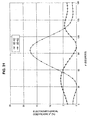
- the electrodes were formed between the piezoelectric substance 2 and the dielectric substance 3, and the relationship of the electrode thickness with the acoustic velocity V, the electromechanical coefficient k 2 , the propagation loss ⁇ , the temperature coefficient of frequency TCF, and the power flow angle PFA were measured. The results are shown in Figs. 2 to 6.
- Figs. 2 to 6 were obtained by calculation based on a method disclosed in "A method for estimating optimal cuts and propagation directions for excitation and propagation directions for excitation of piezoelectric surface waves" (J. J. Campbell, and W. R Jones, IEEE Trans. Sonics and Ultrason., Vol. SU-15 (1968) pp. 209 to 217).
- Vf indicates the acoustic velocity of the free boundary.
- TCF The temperature coefficient of frequency TCF was obtained from phase velocities V at 20°C, 25°C, and 30°C by the following equation (3).
- TCF V -1 (25°C) ⁇ [(V(30°C)-V(20°C))/10°C]- ⁇ s
- ⁇ s is the coefficient of thermal expansion of the LiNbO 3 substrate in the direction of boundary acoustic wave propagation.
- the power flow angle PFA at optional Euler angles ( ⁇ , ⁇ , ⁇ ) was obtained from the phase velocities at angles of ⁇ -0.5°, ⁇ , ⁇ +0.5° by the following equation (4).
- PFA tan -1 [V -1 ( ⁇ ) ⁇ (V( ⁇ +0.5°)-V( ⁇ -0.5°))]
- the acoustic velocities of a longitudinal wave, a fast transverse wave, and a slow transverse wave in the Y plate X propagating LiTaO 3 substrate are 6,547, 4,752, and 4,031 m/second, respectively.
- the acoustic velocities of a longitudinal wave and a slow transverse wave of SiO 2 are 5,960 and 3,757 m/second, respectively.
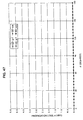
- Fig. 7 is a graph showing the relationship between the density ⁇ of the electrode material and the electrode thickness H at which the propagation loss of the SH type boundary acoustic wave becomes 0. As can be seen from Fig. 7, it is understood that when the following equation (5) holds, an SH type boundary acoustic wave having a propagation loss ⁇ of 0 can be obtained. H( ⁇ )>8,261.744 ⁇ -1.376
- electrodes such as an IDT are formed on a piezoelectric substrate made of LiNbO 3 or the like by a photolithographic method including lift-off, dry etching or the like, and on the electrodes thus formed, a dielectric film made of SiO 2 or the like is formed by a deposition method such as sputtering, evaporation, or CVD.
- a deposition method such as sputtering, evaporation, or CVD.
- the thickness of the electrodes is preferably decreased as small as possible.
- the film thickness H of the electrode material for the IDT or the like is 0.1 ⁇ or more, by the irregularities thereof, it becomes very difficult to form a dielectric thin film having superior quality, and hence the electrode thickness is preferably decreased to 0.1 ⁇ or less. Accordingly, as shown in Fig. 7, it is understood that when an electrode material having a density ⁇ of 3,745 kg/m 3 or more is used, the electrode thickness H at which the propagation loss becomes 0 can be decreased to 0.1 ⁇ .
- the electromechanical coefficient k 2 is large, such as 10% to 38%, and hence a boundary acoustic wave device having a broad band and a low loss can be obtained.
- the temperature coefficient of frequency TCF is in the range of -40 to +40 ppm/°C under most conditions, and that by adjustment of the electrode thickness, TCF can be decreased to ⁇ 20 ppm/°C or less and to ⁇ 10 ppm/°C or less and can be further decreased to ⁇ 0 ppm/°C or less.
- Fig. 8 is a view showing the relationship between the density ⁇ of the electrode material and the electrode thicknesses H at which TCFs of -20, -10, 0, -10 and +20 ppm/°C are obtained, the relationship being indicated by points and an approximation curve thereof.
- an electrode thickness H having a preferable TCF in the range of -20 to +20 ppm/°C is obtained when the following equation (6) holds
- an electrode thickness H having a more preferable TCF in the range of -10 to +10 ppm/°C is obtained when the following equation (7) holds
- an electrode thickness H having a most preferable TCF of 0 ppm/°C is obtained when the following equation (8) holds.
- the power flow angle PFA is advantageously 0 at any film thickness H.
- a boundary acoustic wave resonator shown in Fig. 1 and having the structure shown in Table 3 below was experimentally formed.
- the frequency properties of the boundary acoustic wave resonator thus formed are shown in Fig. 9.
- a Ti film having a thickness of 0.006 ⁇ was formed between the Au and a piezoelectric substance made of the LiNbO 3 .
- the impedance ratio that is, the ratio of the impedance at an antiresonant point to that at a resonant point was 45.6 dB, and the difference between the resonant frequency and the antiresonant frequency was 8.1%; hence, preferable results were obtained.
- the temperature coefficient of frequency TCF of the resonator was 45 ppm/°C.
- a small spurious response indicated by an arrow A was observed around the antiresonant frequency.
- the phenomenon described above may not cause any problem; however, for a ladder boundary acoustic wave filter or a longitudinal coupled resonator type boundary acoustic wave filter using propagation properties around the antiresonant frequency, the phenomenon described above may cause a problem in some cases. Accordingly, in order to increase the range of application of the SH type boundary acoustic wave device and to further improve the properties thereof, the above spurious response is preferably suppressed.
- the above spurious response generated around the antiresonant frequency in EXAMPLE 2 is a response of a Stoneley wave confined around the electrodes disposed at the boundary between SiO 2 and LiNbO 3 due to the increase in thickness of the electrodes as is the case of the SH type boundary acoustic wave. Since the acoustic velocity of the Stoneley wave is low than that of the SH type boundary acoustic wave in many cases, even when the electrode thickness is small as compared to that of the case of the SH type boundary acoustic wave, the Stoneley wave is present as a boundary acoustic wave.
- the SH type boundary acoustic wave has large attenuation and does not propagate unless the thickness of the Au electrode is 0.0105 ⁇ or more; however, even when the thickness of the Au electrode is 0, although the attenuation thereof is not 0, the Stoneley wave may propagate.
- the Euler angles were set to (0°, 0°, ⁇ ), (0°, 90°, ⁇ ), (90°, 0°, ⁇ ), (90°, 90°, ⁇ ), (0°, ⁇ , 0°), (0°, ⁇ , 90°), (90°, ⁇ , 0°), (90°, ⁇ , 90°), ( ⁇ , 0°, 0°), ( ⁇ , 0°, 90°), ( ⁇ , 90°, 0°), and ( ⁇ , 90°, 90°), in which ⁇ , ⁇ , ⁇ were each in the range of 0° to 180°.
- the value provided with a subscript of m indicates the calculated value in a short circuit boundary in which a metal film is disposed between the SiO 2 film and the LiNbO 3 substrate
- the value provided with a subscript f indicates the calculated value in a virtual free boundary obtained by assuming that the relative dielectric constant of a metal film is 1.
- the value provided with a prefix U2 indicates the calculated value of the SH type boundary acoustic wave
- the value provided with a prefix U3 indicates the calculated value of the Stoneley wave.
- the electromechanical coefficient k 2 of the Stoneley wave is 2% or less, since the degradation in properties based on the spurious caused by the Stoneley wave is small, a boundary acoustic wave device using the SH type boundary acoustic wave can be used for relatively limited application.
- the electromechanical coefficient k 2 is more preferably 1% or less, and in this case, the boundary acoustic wave device can be more widely used.
- the electromechanical coefficient k 2 of the Stoneley wave is even more preferably 0.1% or less, and in this case, since influence of the spurious of the Stoneley wave can be substantially ignored, the boundary acoustic wave device may be used for a filter required to have a large attenuation or a highly precise resonator in which a minute spurious resonant response is not accepted.
- the Euler angles at which the electromechanical coefficient k 2 of the Stoneley wave is 2% or less are in the range of (0°, 90°, 0°) to (0°, 90°, 50°), (0°, 90°, 130°) to (0°, 90°, 180°), (90°, 90°, 0°) to (90°, 90°, 60°), (90°, 90°, 143°) to (90°, 90°, 180°), (0°, 84°, 0°) to (0°, 120°, 0°), (90°, 68°, 90°) to (90°, 112°, 90°), and (0°, 90°, 0°) to (180°, 90°, 0°); the Euler angles at which k 2 of the Stoneley wave is 1% or less are in the range of (90°, 90°, 0°) to (90°, 90°, 52°), (90°, 90°, 164°) to (90°, 90°, 180
- a boundary acoustic wave device using the SH type boundary acoustic wave can also be provided in which the spurious response is small or the spurious is not generated.
- the acoustic velocities U2-Vm of the SH type boundary acoustic wave are mostly in the range of approximately 3,000 to 3,400 m/second, and that the change caused by the cut angle is small.
- the temperature coefficients of frequency U2-TCFm of the SH type boundary acoustic wave are mostly in the range of -30 to -39 ppm/°C, and that the change caused by the cur angle is not so significant.
- the electrode thickness H can be determined so as to decrease the temperature coefficient of frequency TCF.
- a superior power flow angle U2-PFAm such as an absolute value of 1° or less, of the SH type boundary acoustic wave can be obtained when the Euler angles are in the range of (0°, 0°, 0°) to (0°, 0°, 180°), (0°, 90°, 0°) to (0°, 90°, 10°), (0°, 90°, 74°) to (0°, 90°, 106°), (0°, 90°, 170°) to (0°, 90°, 180°), (90°, 0°, 0°) to (90°, 0°, 180°), (90°, 90°, 12°) to (90°, 90°, 31°), (90°, 90°, 106°) to (90°, 90°, 117°), (0°, 0°, 0°) to (0°, 180°, 0°), (0°, 0°, 90°) to (0°, 180°, 90°), (90°, 0°, 0°) to to (0°
- the electromechanical coefficient k 2 of the SH type boundary acoustic wave is 5% or more which is sufficiently large so as to form an RF filter;
- a boundary acoustic wave device was formed by forming electrodes made of Au having a thickness of 0.05 ⁇ on a LiNbO 3 substrate having Euler angles (0°, ⁇ , 0°), and then forming a SiO 2 film so as to cover the Au electrodes.
- the relationship of the Euler angle ⁇ on the LiNbO 3 substrate with the acoustic velocities V, the electromechanical coefficients k 2 , and the temperature coefficients of frequency TCF of the SH type boundary acoustic wave and the Stoneley wave were measured. The results are shown in Figs. 87 to 89.
- a boundary acoustic wave device was formed by forming electrodes made of Au having a thickness of 0.06 ⁇ on a LiNbO 3 substrate having Euler angles (0°, ⁇ , ⁇ ), and then forming a SiO 2 film on the electrodes made of Au.
- the relationship of the Euler angles ⁇ and ⁇ of the LiNbO 3 substrate with the acoustic velocities V, the electromechanical coefficients k 2 , the propagation losses ⁇ , and the temperature coefficients of frequency TCF of the SH type boundary acoustic wave and the Stoneley wave were measured.
- the results of the SH type boundary acoustic wave are shown in Figs. 77, and the results of the Stoneley wave are shown in Figs. 78.
- the electromechanical coefficient k 2 which is the response of the Stoneley wave, is small, such as 1.5% or less, in a region surrounded by points from A01 to A13 shown in Table 4 below.
- the electromechanical coefficient k 2 is preferably decreased to 1.0% or less, and in a region surrounded by points from C01 to C08 shown in Table 6 below, k 2 is more preferably decreased to 0.5% or less.
- the electromechanical coefficient k 2 is approximately 0%.
- the electromechanical coefficient k 2 of the SH type boundary acoustic wave is large, such as 2% or more, in a region surrounded by points F01 to F06 in Table 9 below; the electromechanical coefficient k 2 is preferably increased to 5% or more in a region surrounded by points E01 to E07 in Table 8 below; and the electromechanical coefficient k 2 is even more preferably increased to 10% or more in a region surrounded by points D01 to D07 in Table 7 below and becomes maximum at Euler angles (0°, 97°, 0°).
- Boundary acoustic wave devices were formed by forming electrodes made of Au having a thickness of 0.06 ⁇ on respective LiNbO 3 substrates having Euler angles ( ⁇ , 105°, 0°) and (0°, 105°, ⁇ ) and then forming SiO 2 films so as to cover the Au electrodes.
- the relationship of the Euler angles ⁇ and ⁇ of the LiNbO 3 substrates with the acoustic velocities V, the electromechanical coefficients k 2 , the propagation losses ⁇ , the temperature coefficients of frequency TCF, and the power flow PFAs of the SH type boundary acoustic wave and the Stoneley wave were measured. Figs.
- 79 to 82 show the results obtained when the LiNbO 3 substrate having Euler angles ( ⁇ , 105°, 0°) was used, and Figs. 83 to 86 show the results obtained when the LiNbO 3 substrate having Euler angles (0°, 105°, ⁇ ) was used.
- the propagation loss ⁇ is 0 dB/ ⁇ .
- TCF of the SH boundary acoustic wave is preferably in the range of -37 to -35 ppm/°C.
- the electromechanical coefficient k 2 of the Stoneley wave is small, such as 1.5% or less, in the range in which ⁇ is 0° to 53°; the electromechanical coefficient k 2 of the Stoneley wave is further decreased to 1.0% or less in the range in which ⁇ is 0° to 47°; and the electromechanical coefficient k 2 of the Stoneley wave is decreased to 0.5% or less in the range in which ⁇ is 0° to 38°.
- ⁇ is 0°
- the electromechanical coefficient k 2 of the Stoneley wave is decreased to approximately 0%, and hence it is understood that the spurious response caused by the Stoneley wave is decreased.
- a superior TCF of the SH boundary acoustic wave having -35 to -31 ppm/°C can be obtained.
- Fig. 70 is a schematic plan view showing an electrode structure of the SH type boundary acoustic wave resonator of this embodiment. In this structure, on both sides of an IDT 21, reflectors 22 and 23 were disposed. The impedance properties obtained when a LiNbO 3 having Euler angles (0°, 90°, 0°) was used are as shown in Fig. 71.
- the impedance ratio (ratio between the maximum and the minimum absolute values of impedances of the resonator) is 56.8 dB, and the difference between resonance frequency and antiresonance frequency (value obtained by dividing the absolute value of the difference between the resonant frequency and the antiresonant frequency by the resonant frequency) is 6.9%.
- the impedance properties obtained when a LiNbO 3 having Euler angles (0°, 105°, 0°) was used are as shown in Fig. 72.
- the impedance ratio is 59.4 dB, the difference between resonance frequency and antiresonance frequency is 6.8%, and the TCF is 31 ppm/°C.
- an SH boundary acoustic wave resonator having superior resonant properties can be formed in which the Stoneley spurious is not generated.
- the calculated values of displacement components U1, U2, and U3 of this SH type boundary acoustic wave are shown in Fig. 73.
- the displacements are concentrated around the Au which is the boundary layer and are distributed while oozing into the SiO 2 and the LiNbO 3 .
- the SH boundary acoustic wave is affected by the SiO 2 and LiNbO 3 each having high acoustic velocities, and as a result, the acoustic velocity of the SH type boundary acoustic wave cannot be decreased lower than that of the slow transverse wave of the SiO 2 .
- the acoustic velocity of the SH type boundary acoustic wave can be decreased lower than that of the slow transverse wave of the SiO 2 .
- the market for this application can be expected to grow.
- the band width of a longitudinal coupled resonator filter or that of a ladder type filter and the difference between the resonance frequency and the antiresonance frequency of a resonator are in direct proportion to the electromechanical coefficient k 2 . According to the graph shown in Fig.
- 74 is a graph showing the impedance properties obtained when a LiNbO 3 was used having ⁇ of Euler angles (90°, 90°, ⁇ ) in the range of 0° to 35°.
- Fig. 66 since the electromechanical coefficient k 2 is changed from 17.6% to 5.3% as ⁇ is changed from 0° to 35°, the difference between the resonant and the antiresonant frequencies of the resonator is decreased.
- Fig. 75 is a graph showing the relationship of ⁇ of Euler angles (90°, 90°, ⁇ ) with the difference between the resonant and the antiresonant frequencies and the impedance ratio.
- the Stoneley wave is slow as compared to the SH type boundary acoustic wave; however, when the electrode thickness is increased, the SH type boundary acoustic wave becomes slow as compared to the Stoneley wave.
- concentration of energy of the SH type boundary acoustic wave at a boundary layer having a slow acoustic velocity is significant as compared to that of the Stoneley wave.
- the thickness of the electrode at which the acoustic velocity of the Stoneley wave becomes higher or lower than that of the SH type boundary acoustic wave is changed depending on the Euler angles of the LiNbO 3 substrate; however, at an electrode thickness in the range of 0.01 ⁇ to 0.03 ⁇ , the change in relationship therebetween described above occurred.
- the reason the spurious response caused by the Stoneley wave was generated at a higher frequency side than the response of the SH type boundary acoustic wave in EXAMPLES 2, 4, and 5 is this phenomenon.
- the acoustic velocity of the Stoneley wave becomes higher than that of the SH type boundary acoustic wave.
- the acoustic velocity of the SH type boundary acoustic wave is decreased lower than that of slow transverse waves of two media forming the boundary, and the acoustic velocity of the Stoneley wave is increased higher than that of at least one of the slow transverse waves of the two media forming the boundary, the propagation loss of the Stoneley wave is increased, and hence the spurious response can be suppressed.
- the acoustic velocity of a boundary acoustic wave propagating in the IDT portion can be obtained by multiplying the response frequency of the boundary acoustic wave and a strip period ⁇ I of the IDT.
- the electrode may be formed using a conductive film composed, for example, of Fe, Ni, W, Ta, Pt, Mo, Cr, Ti, ZnO, or ITO.
- a conductive film composed, for example, of Fe, Ni, W, Ta, Pt, Mo, Cr, Ti, ZnO, or ITO.
- at least one second electrode layer made of a different metal material such as Ti, Cr, or a NiCr alloy may be laminated.
- the second electrode layer may be provided between a first electrode layer and the piezoelectric substance or between the first electrode layer and the dielectric substance, or the second electrode layers may be provided at both places described above.
- a protective layer may be formed outside the laminate composed of the dielectric substance, electrodes, and piezoelectric substance along the lamination direction.
- the boundary acoustic wave device of the present invention may be sealed in a package.
- the protective layer described above may be formed of an insulating material such as titanium oxide, aluminum nitride, or aluminum oxide, a metal film such as Au, Al, or W, or a resin such as a urethane, an epoxy, or a silicone resin.
- an insulating material such as titanium oxide, aluminum nitride, or aluminum oxide
- a metal film such as Au, Al, or W
- a resin such as a urethane, an epoxy, or a silicone resin.
- the above piezoelectric substance may be a piezoelectric film formed on a dielectric substance.
- the thickness of the dielectric substance and that of the piezoelectric substance are not required to be infinite as is the model used as the base for calculation and may be sufficient when energy of the boundary acoustic wave is confined around the electrodes which function as the boundary. That is, for example, the thickness may be 1 ⁇ or more.
- the above protective layers are formed outside of a boundary acoustic wave structure composed of a dielectric substance, electrodes, and a piezoelectric substance to form the structure composed, for example, of the protective layer, the dielectric substance, the electrodes, the piezoelectric substance, and the protective layer, and when oscillation is allowed to slightly ooze also into protective layer portions, the thickness of the dielectric substance and that of the piezoelectric substance can be decreased.
- a ladder type filter 24 having a circuit structure shown in Fig.
- the boundary acoustic wave device of the present invention since the IDT is formed using a heavy material, energy of the SH boundary acoustic wave is concentrated at and distributed around the Au-IDT which is the boundary layer, as described above, and the amount of energy oozing from the SiO 2 having a small acoustic damping to the epoxy resin having a large damping is small. Hence, even when the thickness of SiO 2 is decreased, the degradation in loss is small.
- the thickness of the epoxy resin was 3 ⁇
- the thickness of Au was 0.054 ⁇
- the thickness of LN was 146 ⁇
- the Euler angles of the LiNbO 3 were (0°, 105°, 0°).
- the IDT had an open length of 30 ⁇ and 50 pairs having a normal type single strip structure
- the reflector had 50 normal type single strip structures
- the distance between the IDT and the reflector was 0.5 ⁇ as the distance between the centers of adjacent strips
- the period of the IDT was 2.4 ⁇ m which was equal to that of the reflector.
- the electrodes may include a sheet electrode film forming a waveguide or a bus bar, an IDT or comb-shaped electrode exciting a boundary acoustic wave, and a reflector reflecting a boundary acoustic wave.
- a Z' axis is obtained by ⁇ rotation of the Z axis about the Xa axis in an anticlockwise direction.
- a plane including the Xa axis and having the Z' axis as the normal line is set as the cut surface of a substrate.
- the direction of an X' axis obtained by ⁇ rotation of the Xa axis about the Z' axis in an anticlockwise direction is set as the propagation direction of a boundary acoustic wave.
- the Z axis is set parallel to the c-axis
- the X axis is set parallel to any one of the three equivalent a-axes in three different directions
- the Y axis is set parallel to the normal line of a plane including the X axis and the Z axis.
- Euler angles ( ⁇ , ⁇ , ⁇ ) of LiNbO 3 of the present invention Euler angles equivalent thereto from a crystallographic point of view may also used.
- Euler angles equivalent thereto from a crystallographic point of view may also be used.
- F is an optional boundary acoustic-wave property such as the electromechanical coefficient k 2 , propagation loss, TCF, PFA, or a natural unidirectional property.
- PFA and natural unidirectional property for example, when the propagation direction is reversed, although a plus or a minus sign indicating the direction is changed, the absolute value of the property is not changed, and hence it can be construed that they are practically equivalent to each other.
- the technical document 7 relates to the surface acoustic wave, even when the boundary acoustic wave is discussed, the symmetry of crystal may also be handled in the same manner as disclosed the technical document 7.
- propagation properties of a boundary acoustic wave at Euler angles (30°, ⁇ , ⁇ ) are equivalent to those at Euler angles (90°, 180°- ⁇ , 180°- ⁇ ).
- propagation properties of a boundary acoustic wave at Euler angles (30°, 90°, 45°) are equivalent to those at Euler angles shown in Table 12 below.
- the material constant of the electrode used for calculation in the present invention is the value of a polycrystalline substance; however, even in a crystal substance such as an epitaxial film, since the crystal orientation dependence of a substrate dominantly influences the boundary acoustic wave properties as compared to that of the film itself, in the case of the equivalent Euler angles represented by the equation (A), equivalent propagation properties which may not cause any practical problems can be obtained.
Landscapes
- Physics & Mathematics (AREA)
- Acoustics & Sound (AREA)
- Chemical & Material Sciences (AREA)
- Engineering & Computer Science (AREA)
- Materials Engineering (AREA)
- Surface Acoustic Wave Elements And Circuit Networks Thereof (AREA)
- Paper (AREA)
- Electrical Discharge Machining, Electrochemical Machining, And Combined Machining (AREA)
- Soil Working Implements (AREA)
- Shafts, Cranks, Connecting Bars, And Related Bearings (AREA)
- Golf Clubs (AREA)
Abstract
Description
- The present invention relates to a boundary acoustic wave device using an SH type boundary acoustic wave and, in particular, to a boundary acoustic wave device having the structure in which electrodes are disposed at a boundary between a piezoelectric substance and a dielectric substrate.
- Heretofore, various surface acoustic wave devices have been used for RF and IF filters in mobile phones, resonators in VCOs, and VIF filters in televisions. The surface acoustic wave devices employ a surface acoustic wave, such as a Rayleigh wave or a first leaky wave, propagating along a surface of a medium.
- Since propagating along a surface of a medium, a surface acoustic wave is sensitive to the change in surface condition of the medium. Accordingly, in order to protect a surface of a medium along which the surface acoustic wave propagates, a surface acoustic wave element has been hermetic-sealed in a package having a cavity portion so that the surface of the medium described above is placed therein. Since a package having a cavity as described above has been used, the cost of the surface acoustic wave device has been inevitably increased. In addition, since the size of the package becomes much larger than that of a surface acoustic wave element, the size of the surface acoustic wave device has also been inevitably increased.
- Besides the surface acoustic wave described above, of acoustic waves, a boundary acoustic wave is present which propagates along a boundary between solid substances.
- For example, in "Piezoelectric Acoustic Boundary Waves Propagating Along the Interface Between SiO2 and LiTaO3" IEEE Trans. Sonics and ultrason., VOL. SU-25, No. 6, 1978 IEEE, a boundary acoustic wave device has been disclosed in which an IDT is formed on a 126° rotated Y plate X propagating LiTaO3 substrate, and on the IDT and the LiTaO3 substrate, a SiO2 film having a predetermined thickness is formed. In the above technical paper, it has been disclosed that an SV+P type boundary acoustic wave, a so-called Stoneley wave, propagates. In addition, in "Piezoelectric Acoustic Boundary Waves Propagating Along the Interface Between SiO2 and LiTaO3" IEEE Trans. Sonics and ultrason., VOL. SU-25, No. 6, 1978 IEEE, it has also been disclosed that when the film thickness of the SiO2 film described above is set to 1.0 λ (λ indicates the wavelength of a boundary acoustic wave), an electromechanical coefficient of 2% is obtained.
- The boundary acoustic wave propagates when energy thereof is concentrated at a boundary portion between solid substrates. Accordingly, since the energy is not substantially present on the bottom surface of the above LiTaO3 substrate and the surface of the SiO2 film, the properties are not changed due to the change in surface conditions of the substrate and the thin film. Hence, a cavity type package is not required, and as a result, the size of the acoustic wave device can be reduced.
- In addition, in "Highly Piezoelectric Boundary Acoustic Wave Propagating in Si/SiO2/LiNbO3 Structure" (26th EM symposium, May 1997, pp. 53 to 58), an SH type boundary acoustic wave has been disclosed propagating in a [001]-Si(110)/SiO2/Y-cut X propagating LiNbO3 structure. This SH type boundary acoustic wave is characterized in that an electromechanical coefficient k2 is large as compared to that of the Stoneley wave. In addition, also in the case of the SH type boundary acoustic wave, as is the case of the Stoneley wave, the cavity type package is not required. Furthermore, since the SH type boundary acoustic wave is an SH type wave, it is expected that the reflection coefficient of strips forming an IDT reflector is large as compared to that of the Stoneley wave. Hence, for example, when a resonator or a resonator filter is formed, by using the SH type boundary acoustic wave, miniaturization can be achieved, and in addition, it is expected to obtain steeper properties.
- As a boundary acoustic wave device, a large electromechanical coefficient is required, and in addition, small propagation loss, power flow angle, and temperature coefficient of frequency are also required. A loss occurring concomitant with propagation of the boundary acoustic wave, that is, the propagation loss degrades the insertion loss of a boundary acoustic wave filter or degrades an impedance ratio of a boundary acoustic resonator, the impedance ratio being a ratio between a resonant resistance or the impedance at a resonant frequency and the impedance at an antiresonant frequency. Accordingly, a smaller propagation loss is more preferable.
- The power flow angle is an angle showing the difference in direction between the phase velocity of a boundary acoustic wave and the group velocity of energy thereof. When the power flow angle is large, an IDT must be obliquely disposed in conformity with the power flow angle. As a result, designing of electrodes becomes complicated. In addition, due to the deviation in angle, the generation of loss is liable to occur.
- Furthermore, when operating frequency of a boundary acoustic wave device is changed by temperature, in the case of a boundary acoustic wave filter, practical passband and stopband regions are decreased. In the case of a resonator, the change in operating frequency by temperature described above causes abnormal oscillation when an oscillation circuit is formed. Hence, it is more preferable when the change in frequency per degree centigrade, i.e., TCF, is smaller.
- For example, when reflectors are provided along a propagation direction and outside a region in which a transmitting and a receiving IDT, which respectively transmits and receives a boundary acoustic wave, are provided, a resonant filter having a low loss can be formed. The band width of this resonant filter depends on the electromechanical coefficient of the boundary acoustic wave. When the electromechanical coefficient k2 is large, a wide band filter can be obtained, and when it is small, a narrow band filter is formed. Accordingly, the electromechanical coefficient k2 of a boundary acoustic wave which is used for a boundary acoustic wave device is required to have an appropriate value in consideration of its application. When an RF filter for mobile phones is formed, the electromechanical coefficient k2 is required to be 5% or more.
- However, in the boundary acoustic wave device using a Stoneley wave, disclosed in "Piezoelectric Acoustic Boundary Waves Propagating Along the Interface Between SiO2 and LiTaO3" IEEE Trans. Sonics and ultrason., VOL. SU-25, No. 6, 1978 IEEE, the electromechanical coefficient k2 was small, such as 2%.
- In addition, in the Si/SiO2/LiNbO3 Structure disclosed in "Highly Piezoelectric Boundary Wave Propagating in Si/SiO2/LiNbO3 Structure" (26th EM symposium, May 1997, pp. 53 to 58), in order to actually excite the boundary acoustic wave, as shown in Fig. 1 of Japanese Unexamined Patent Application Publication No. 10-84247, it was required to form a complicated four-layered structure of Si/SiO2/IDT/LiNbO3. Furthermore, when Si was actually disposed in the [001]-Si(110) orientation proposed as the most optimal conditions, a bonding method of high degree of difficulty had to be used as disclosed in Japanese Unexamined Patent Application Publication No. 10-84247. In general, it has been difficult to uniformly bond a wafer having a diameter of 3 inches or more, which is used for mass production, by a bonding method. In addition, when the wafer was cut into chips after bonding, defects such as peeling were liable to occur.
- As for the SH type boundary acoustic wave, as disclosed in "Investigation of Piezoelectric SH Type Boundary Acoustic Wave", Technical Report, The Institute of Electronics, Information and Communication Engineers, Vol. 96, No. 249 (US96 45-53) PAGE. 21 to 26, 1966, in the structure composed of an isotropic substance and a BGSW substrate, when the conditions are satisfied in that the acoustic velocity of a transverse wave of the isotropic substance and that of a transverse wave of the BGSW substrate are close to each other, the density ratio is small, and the piezoelectric properties are strong, the SH type boundary acoustic wave can be obtained.
- However, due to limitation of materials capable of satisfying the conditions described above, it was difficult to satisfy the aforementioned various performances and properties required for the boundary acoustic wave. For example, in the [001]-Si(110)/X-LiNbO3 structure disclosed in "Highly Piezoelectric Boundary Wave Propagating in Si/SiO2/LiNbO3 Structure" (26th EM symposium, May 1997, pp. 53 to 58), it was necessary to use a bonding method of high degree of difficulty for production.
- In consideration of the current status of the conventional techniques described above, an object of the present invention is to provide a boundary acoustic wave device using an SH type boundary acoustic wave, the boundary acoustic wave device having a large electromechanical coefficient, small propagation loss and power flow angle, a temperature coefficient of frequency TCF in an appropriate range, and a simple structure which can be manufacture by a simple method.
- In accordance with a first aspect of the present invention, there is provide a boundary acoustic wave device comprising a piezoelectric substance, a dielectric substance laminated on one surface of the piezoelectric substance, and electrodes disposed at a boundary between the piezoelectric substance and the dielectric substance, in which the boundary acoustic wave device uses an SH type boundary acoustic wave propagating along the boundary. In the boundary acoustic wave device described above, the thickness of the electrodes is determined so that the acoustic velocity of the SH type boundary acoustic wave is low as compared to that of a slow transverse wave propagating in the dielectric substance and to that of a slow transverse wave propagating in the piezoelectric substance.
- In accordance with a second aspect of the present invention, there is provided a boundary acoustic wave device comprising a piezoelectric substance, a dielectric substance laminated on one surface of the piezoelectric substance, and electrodes disposed at a boundary between the piezoelectric substance and the dielectric substance, in which the boundary acoustic wave device uses an SH type boundary acoustic wave propagating along the boundary. In the boundary acoustic wave device described above, the duty ratio of strips forming the electrodes is determined so that the acoustic velocity of the SH type boundary acoustic wave is low as compared to that of a slow transverse wave propagating in the dielectric substance and to that of a slow transverse wave propagating in the piezoelectric substance.
- In accordance with a third aspect of the present invention, there is provided a boundary acoustic wave device comprising a piezoelectric substance primarily composed of LiNbO3, a dielectric substance laminated on one surface of the piezoelectric substance, and electrodes disposed at a boundary between the piezoelectric substance and the dielectric substance, in which the boundary acoustic wave device uses an SH type boundary acoustic wave propagating along the boundary. In the boundary acoustic wave device described above, of Euler angles (, , ψ) of the piezoelectric substance primarily composed of LiNbO3 is in the range of -31° to +31°, and and ψ are in a region surrounded by points A01 to A13 in Table 1 below.
POINT ψ(°) (°) A01 0 116 A02 11 118 A03 20 123 A04 25 127 A05 33 140 A06 60 140 A07 65 132 A08 54 112 A09 48 90 A10 43 87 A11 24 90 A12 0 91 A13 0 116 - In the boundary acoustic wave device according to the third aspect of the present invention, and ψ of the Euler angles are in a region surrounded by points D01 to D07 in Table 2 below.
POINT ψ(°) (°) D01 0 126 D02 13 123 D03 25 112 D04 30 96 D05 29 80 D06 0 80 D07 0 126 - In the boundary acoustic wave device according to the third aspect of the present invention, the thickness of the electrodes is determined so that the acoustic velocity of the SH type boundary acoustic wave is low as compared to that of a slow transverse wave propagating in the dielectric substance and to that of a slow transverse wave propagating in the piezoelectric substance.
- According to the third aspect of the present invention, the duty ratio of strips forming the electrodes is determined so that the acoustic velocity of the SH type boundary acoustic wave is low as compared to that of a slow transverse wave propagating in the dielectric substance and to that of a slow transverse wave propagating in the piezoelectric substance.
- In accordance with a fourth aspect of the present invention, there is provided a boundary acoustic wave device comprising a piezoelectric substance primarily composed of LiNbO3, a dielectric substance laminated on one surface of the piezoelectric substance and primarily composed of SiO2, and electrodes disposed at a boundary between the piezoelectric substance and the dielectric substance. In the boundary acoustic wave device described above, when the density of the electrodes, the thickness of the electrodes, and the wavelength of a boundary acoustic wave are represented by ρ (kg/m3), H (λ), and λ, respectively, H>8,261.744ρ-1.376 holds, and Euler angles of the piezoelectric substance are in the range of (0°, 90°, 0°) to (0°, 90°, 38°), (0°, 90°, 142°) to (0°, 90°, 180°), (90°, 90°, 0°) to (90°, 90°, 36°), (90°, 90°, 140°) to (90°, 90°, 180°), (0°, 55°, 0°) to (0°, 134°, 0°), (90°, 51°, 0°) to (90°, 129°, 0°), or (0°, 90°, 0°) to (180°, 90°, 0°).
- According to the fourth aspect of the present invention, the Euler angles of the piezoelectric substance are equivalent to Euler angles represented by the following equation (A) at which boundary acoustic wave properties are obtained which are substantially equivalent to those of the piezoelectric substance.

- In accordance with a fifth aspect of the present invention, there is provided a boundary acoustic wave device comprising a piezoelectric substance primarily composed of LiNbO3, a dielectric substance laminated on one surface of the piezoelectric substance and primarily composed of SiO2, and electrodes disposed at a boundary between the piezoelectric substance and the dielectric substance, in which the boundary acoustic wave device uses an SH type boundary acoustic wave propagating along the boundary. In the boundary acoustic wave device described above, when the density of the electrodes, the thickness of the electrodes, and the wavelength of the boundary acoustic wave are represented by ρ (kg/m3), H (λ), and λ, respectively, H>8,261.744ρ-1.376 holds.
- In the boundary acoustic wave device according to one of the third to the fifth aspects, the density p of the electrodes is preferably more than 3,745 kg/m3.
- In the boundary acoustic wave device according to one of the third to the fifth aspects, the thickness H of the electrodes satisfies the following equation (1).
- In accordance with a sixth aspect of the present invention, there is provided a boundary acoustic wave device comprising a boundary acoustic-wave propagation structure in which an SH type boundary acoustic wave and a Stoneley wave propagate. In the boundary acoustic wave device described above, the acoustic velocity of the SH type boundary acoustic wave is low as compared to that of slow transverse waves of two media forming a boundary, and the acoustic velocity of the Stoneley wave is high as compared to that of at least one of the slow transverse waves of the two media.
- According to one of the first to the sixth aspects of the present invention, the electrodes each preferably primarily comprise an electrode layer which is composed of at least one selected from the group consisting of Au, Ag, Cu, Al, Fe, Ni, W, Ta, Pt, Mo, Cr, Ti, ZnO, ITO, and an alloy primarily containing at least one of the above conductive materials.
- In addition, besides the electrode layer, the electrodes may each further comprise at least one second electrode layer containing a conductive material other than the conductive materials forming the electrode layer.
- In the boundary acoustic wave device of the first aspect according to the present invention, there are provided the piezoelectric substance, the dielectric substance laminated on one surface of the piezoelectric substance, and the electrodes disposed at the boundary between the piezoelectric substance and the dielectric substance, and the thickness of the electrodes is determined so that the acoustic velocity of the SH type boundary acoustic wave is low as compared to that of a slow transverse wave propagating in the dielectric substance and to that of a slow transverse wave propagating in the piezoelectric substance.
- In addition, according to the second aspect of the present invention, there are provided the piezoelectric substance, the dielectric substance laminated on one surface of the piezoelectric substance, and the electrodes disposed at the boundary between the piezoelectric substance and the dielectric substance, and the duty ratio of the strips forming the electrodes is determined so that the acoustic velocity of the SH type boundary acoustic wave is low as compared to that of a slow transverse wave propagating in the dielectric substance and to that of a slow transverse wave propagating in the piezoelectric substance.
- According to the first and the second aspects of the present invention, since the thickness of the electrodes or the duty ratio of the sprits is determined as described above, an SH type boundary acoustic wave device can be provided in which the SH type boundary acoustic wave propagates in the dielectric substance and in the piezoelectric substance.
- In the boundary acoustic wave device of the third aspect according to the present invention, since the piezoelectric substance primarily composed of LiNbO3 is used, of the Euler angles (, , ψ) of the LiNbO3 is in the range of -31° to +31°, and and ψ are in the region surrounded by the points A01 to A13 in Table 1 described above, the spurious caused by the Stoneley wave can be effectively suppressed, and the electromechanical coefficient k2 of the SH type boundary acoustic wave can be increased.
- In particular, when and ψ of the Euler angles are in the region surrounded by the points D01 to D07 in Table 2, the electromechanical coefficient k2 of the SH type boundary acoustic wave can be increased to 10% or more.
- In addition, in the boundary acoustic wave device of the third aspect according to the present invention, when the thickness of the electrodes is determined so that the acoustic velocity of the SH type boundary acoustic wave is low as compared to that of a slow transverse wave propagating in the dielectric substance and to that of a slow transverse wave propagating in the piezoelectric substance, or when the duty ratio of the strips forming the electrodes is determined so that the acoustic velocity of the SH type boundary acoustic wave is low as compared to that of a slow transverse wave propagating in the dielectric substance and to that of a slow transverse wave propagating in the piezoelectric substance, an SH type boundary acoustic wave device can be provided in which the SH type boundary acoustic wave reliably propagates along the boundary between the dielectric substance and the piezoelectric substance.
- According to the boundary acoustic wave device of the fourth aspect of the present invention, in the structure in which the dielectric substance primarily composed of SiO2 is laminated on one surface of the piezoelectric substance primarily composed of LiNbO3, and in which the electrodes are disposed at the boundary between the piezoelectric substance and the dielectric substance, since H>8,261.744ρ- 1.376 holds, and the Euler angles of the piezoelectric substance are in the specific region described above, a boundary acoustic wave device can be provided which uses a boundary acoustic wave and which has a large electromechanical coefficient.
- In addition, in the boundary acoustic wave device of the fourth aspect according to the present invention, the Euler angles of the piezoelectric substance described above may be substituted for Euler angles represented by the equation (A) at which boundary acoustic wave properties are substantially equivalent to those of the piezoelectric substance.
- According to the fifth aspect of the present invention, since there are provided the piezoelectric substance primarily composed of LiNbO3, the dielectric substance laminated on one surface of the piezoelectric substance and primarily composed of SiO2, and the electrodes disposed at the boundary between the piezoelectric substance and the dielectric substance, and when the density of the electrodes, the thickness of the electrodes, and the wavelength of the boundary acoustic wave are represented by ρ (kg/m3), H (λ), and λ, respectively, since H>8,261.744ρ-1.376 holds, a boundary acoustic wave device can be provided which can propagate the SH type boundary acoustic wave while the spurious caused by the Stoneley wave can be effectively suppressed.
- In addition, according to the third to the fifth aspects of the present invention, when the density ρ is more than 3,745 kg/m3, the thickness of the electrodes at which the propagation loss is 0 can be decreased. Hence, the electrodes can be easily formed.
- Furthermore, when the electrode thickness H satisfies the above equation (1), the temperature coefficient of frequency TCF of the SH type boundary acoustic wave can be decreased to ± 20 ppm or less.
- According to the sixth aspect of the present invention, in the boundary acoustic wave device having the boundary acoustic-wave propagation structure in which the SH type boundary acoustic wave and the Stoneley wave propagate, since the acoustic velocity of the SH type boundary acoustic wave is low as compared to that of slow transverse waves of two media forming a boundary, and the acoustic velocity of the Stoneley wave is high as compared to that of at least one of the slow transverse waves of the two media, the propagation loss of the Stoneley wave is degraded, thereby the spurious caused by the Stoneley wave is suppressed, and as a result, frequency properties of a boundary acoustic wave device using the SH type boundary acoustic wave can be improved.
- In the present invention, when the electrodes each primarily comprise an electrode layer which is composed of at least one selected from the group consisting of Au, Ag, Cu, Al, Fe, Ni, W, Ta, Pt, Mo, Cr, Ti, ZnO, ITO, and an alloy primarily containing at least one of the above metals, a boundary acoustic wave device using the SH type boundary acoustic wave can be provided according to the present invention. In addition, when the electrodes each further comprise at least one second electrode layer composed of a metal other than the metals forming the electrode layer, by selecting a metal material forming the second electrode layer, the adhesion between the electrodes and the dielectric substance or the piezoelectric substance can be improved, or electric power resistance can be improved.
-
- Fig. 1 is a front cross-sectional view of a boundary acoustic wave device of one embodiment according to the present invention.
- Fig. 2 is a graph showing the relationship between the acoustic velocity V and the thickness H/λ of an electrode, which is obtained when electrodes are each formed between a piezoelectric substance and a dielectric substance using electrode materials having different densities.
- Fig. 3 is a graph showing the relationship between the propagation loss α and the thickness H/λ of an electrode, which is obtained when electrodes are each formed between a piezoelectric substance and a dielectric substance using electrode materials having different densities.
- Fig. 4 is a graph showing the relationship between the electromechanical coefficient k2 and the thickness H/λ of an electrode, which is obtained when electrodes are each formed between a piezoelectric substance and a dielectric substance using electrode materials having different densities.
- Fig. 5 is a graph showing the relationship between the temperature coefficient of frequency TCF and the thickness H/λ of an electrode, which is obtained when electrodes are each formed between a piezoelectric substance and a dielectric substance using electrode materials having different densities.
- Fig. 6 is a graph showing the relationship between the power flow angle PFA and the thickness H/λ of an electrode, which is obtained when electrodes are each formed between a piezoelectric substance and a dielectric substance using electrode materials having different densities.
- Fig. 7 is a graph showing the relationship between the density ρ of an electrode material and the electrode thickness H (λ) at which the propagation loss is 0.
- Fig. 8 is a graph showing the relationship between the density ρ of an electrode material and the electrode thickness H (λ) at which TCF is -20, -10, 0, +10, and +20 ppm/°C.
- Fig. 9 is a graph showing the frequency properties of a boundary acoustic wave resonator experimentally formed in EXAMPLE 2.
- Fig. 10 is a graph showing the relationship between Euler angle and the acoustic velocity V in the structure in which Au electrodes are formed on a LiNbO3 substrate having Euler angles (, 0°, 0°) and a SiO2 film is formed.
- Fig. 11 is a graph showing the relationship between Euler angle and the electromechanical coefficient k2 in the structure in which Au electrodes are formed on a LiNbO3 substrate having Euler angles (, 0°, 0°) and a Si02 film is formed.
- Fig. 12 is a graph showing the relationship between Euler angle and the propagation loss α in the structure in which Au electrodes are formed on a LiNbO3 substrate having Euler angles (, 0°, 0°) and a SiO2 film is formed.
- Fig. 13 is a graph showing the relationship between Euler angle and the temperature coefficient of frequency TCF in the structure in which Au electrodes are formed on a LiNbO3 substrate having Euler angles (, 0°, 0°) and a Si02 film is formed.
- Fig. 14 is a graph showing the relationship between Euler angle and the power flow angle PFA in the structure in which Au electrodes are formed on a LiNbO3 substrate having Euler angles (, 0°, 0°) and a Si02 film is formed.
- Fig. 15 is a graph showing the relationship between Euler angle and the acoustic velocity V in the structure in which Au electrodes are formed on a LiNbO3 substrate having Euler angles (, 0°, 90°) and a Si02 film is formed.
- Fig. 16 is a graph showing the relationship between Euler angle and the electromechanical coefficient k2 in the structure in which Au electrodes are formed on a LiNbO3 substrate having Euler angles (, 0°, 90°) and a Si02 film is formed.
- Fig. 17 is a graph showing the relationship between Euler angle and the propagation loss α in the structure in which Au electrodes are formed on a LiNbO3 substrate having Euler angles (, 0°, 90°) and a Si02 film is formed.
- Fig. 18 is a graph showing the relationship between Euler angle and the temperature coefficient of frequency TCF in the structure in which Au electrodes are formed on a LiNbO3 substrate having Euler angles (, 0°, 90°) and a SiO2 film is formed.
- Fig. 19 is a graph showing the relationship between Euler angle and the power flow angle PFA in the structure in which Au electrodes are formed on a LiNbO3 substrate having Euler angles (, 0°, 90°) and a SiO2 film is formed.
- Fig. 20 is a graph showing the relationship between Euler angle and the acoustic velocity V in the structure in which Au electrodes are formed on a LiNbO3 substrate having Euler angles (, 90°, 0°) and a Si02 film is formed.
- Fig. 21 is a graph showing the relationship between Euler angle and the electromechanical coefficient k2 in the structure in which Au electrodes are formed on a LiNbO3 substrate having Euler angles (, 90°, 0°) and a SiO2 film is formed.
- Fig. 22 is a graph showing the relationship between Euler angle and the propagation loss α in the structure in which Au electrodes are formed on a LiNbO3 substrate having Euler angles (, 90°, 0°) and a Si02 film is formed.
- Fig. 23 is a graph showing the relationship between Euler angle and the temperature coefficient of frequency TCF in the structure in which Au electrodes are formed on a LiNbO3 substrate having Euler angles (, 90°, 0°) and a Si02 film is formed.
- Fig. 24 is a graph showing the relationship between Euler angle and the power flow angle PFA in the structure in which Au electrodes are formed on a LiNbO3 substrate having Euler angles (, 90°, 0°) and a Si02 film is formed.
- Fig. 25 is a graph showing the relationship between Euler angle and the acoustic velocity V in the structure in which Au electrodes are formed on a LiNbO3 substrate having Euler angles (, 90°, 90°) and a SiO2 film is formed.
- Fig. 26 is a graph showing the relationship between Euler angle and the electromechanical coefficient k2 in the structure in which Au electrodes are formed on a LiNbO3 substrate having Euler angles (, 90°, 90°) and a Si02 film is formed.
- Fig. 27 is a graph showing the relationship between Euler angle and the propagation loss α in the structure in which Au electrodes are formed on a LiNbO3 substrate having Euler angles (, 90°, 90°) and a Si02 film is formed.
- Fig. 28 is a graph showing the relationship between Euler angle and the temperature coefficient of frequency TCF in the structure in which Au electrodes are formed on a LiNbO3 substrate having Euler angles (, 90°, 90°) and a Si02 film is formed.
- Fig. 29 is a graph showing the relationship between Euler angle and the power flow angle PFA in the structure in which Au electrodes are formed on a LiNbO3 substrate having Euler angles (, 90°, 90°) and a SiO2 film is formed.
- Fig. 30 is a graph showing the relationship between Euler angle and the acoustic velocity V in the structure in which Au electrodes are formed on a LiNbO3 substrate having Euler angles (0°, , 0°) and a Si02 film is formed.
- Fig. 31 is a graph showing the relationship between Euler angle and the electromechanical coefficient k2 in the structure in which Au electrodes are formed on a LiNbO3 substrate having Euler angles (0°, , 0°) and a Si02 film is formed.
- Fig. 32 is a graph showing the relationship between Euler angle and the propagation loss α in the structure in which Au electrodes are formed on a LiNbO3 substrate having Euler angles (0°, , 0°) and a Si02 film is formed.
- Fig. 33 is a graph showing the relationship between Euler angle and the temperature coefficient of frequency TCF in the structure in which Au electrodes are formed on a LiNbO3 substrate having Euler angles (0°, , 0°) and a Si02 film is formed.
- Fig. 34 is a graph showing the relationship between Euler angle and the power flow angle PFA in the structure in which Au electrodes are formed on a LiNbO3 substrate having Euler angles (0°, , 0°) and a SiO2 film is formed.
- Fig. 35 is a graph showing the relationship between Euler angle and the acoustic velocity V in the structure in which Au electrodes are formed on a LiNbO3 substrate having Euler angles (0°, , 90°) and a Si02 film is formed.
- Fig. 36 is a graph showing the relationship between Euler angle and the electromechanical coefficient k2 in the structure in which Au electrodes are formed on a LiNbO3 substrate having Euler angles (0°, , 90°) and a SiO2 film is formed.
- Fig. 37 is a graph showing the relationship between Euler angle and the propagation loss α in the structure in which Au electrodes are formed on a LiNbO3 substrate having Euler angles (0°, , 90°) and a Si02 film is formed.
- Fig. 38 is a graph showing the relationship between Euler angle and the temperature coefficient of frequency TCF in the structure in which Au electrodes are formed on a LiNbO3 substrate having Euler angles (0°, , 90°) and a SiO2 film is formed.
- Fig. 39 is a graph showing the relationship between Euler angle and the power flow angle PFA in the structure in which Au electrodes are formed on a LiNbO3 substrate having Euler angles (0°, , 90°) and a SiO2 film is formed.
- Fig. 40 is a graph showing the relationship between Euler angle and the acoustic velocity V in the structure in which Au electrodes are formed on a LiNbO3 substrate having Euler angles (90°, , 0°) and a SiO2 film is formed.
- Fig. 41 is a graph showing the relationship between Euler angle and the electromechanical coefficient k2 in the structure in which Au electrodes are formed on a LiNbO3 substrate having Euler angles (90°, , 0°) and a SiO2 film is formed.
- Fig. 42 is a graph showing the relationship between Euler angle and the propagation loss α in the structure in which Au electrodes are formed on a LiNbO3 substrate having Euler angles (90°, , 0°) and a Si02 film is formed.
- Fig. 43 is a graph showing the relationship between Euler angle and the temperature coefficient of frequency TCF in the structure in which Au electrodes are formed on a LiNbO3 substrate having Euler angles (90°, , 0°) and a Si02 film is formed.
- Fig. 44 is a graph showing the relationship between Euler angle and the power flow angle PFA in the structure in which Au electrodes are formed on a LiNbO3 substrate having Euler angles (90°, , 0°) and a SiO2 film is formed.
- Fig. 45 is a graph showing the relationship between Euler angle and the acoustic velocity V in the structure in which Au electrodes are formed on a LiNbO3 substrate having Euler angles (90°, , 90°) and a Si02 film is formed.
- Fig. 46 is a graph showing the relationship between Euler angle and the electromechanical coefficient k2 in the structure in which Au electrodes are formed on a LiNbO3 substrate having Euler angles (90°, , 90°) and a Si02 film is formed.
- Fig. 47 is a graph showing the relationship between Euler angle and the propagation loss α in the structure in which Au electrodes are formed on a LiNbO3 substrate having Euler angles (90°, , 90°) and a Si02 film is formed.
- Fig. 48 is a graph showing the relationship between Euler angle and the temperature coefficient of frequency TCF in the structure in which Au electrodes are formed on a LiNbO3 substrate having Euler angles (90°, , 90°) and a Si02 film is formed.
- Fig. 49 is a graph showing the relationship between Euler angle and the power flow angle PFA in the structure in which Au electrodes are formed on a LiNbO3 substrate having Euler angles (90°, , 90°) and a Si02 film is formed.
- Fig. 50 is a graph showing the relationship between Euler angle ψ and the acoustic velocity V in the structure in which Au electrodes are formed on a LiNbO3 substrate having Euler angles (0°, 0°, ψ) and a Si02 film is formed.
- Fig. 51 is a graph showing the relationship between Euler angle ψ and the electromechanical coefficient k2 in the structure in which Au electrodes are formed on a LiNbO3 substrate having Euler angles (0°, 0°, ψ) and a SiO2 film is formed.
- Fig. 52 is a graph showing the relationship between Euler angle ψ and the propagation loss α in the structure in which Au electrodes are formed on a LiNbO3 substrate having Euler angles (0°, 0°, ψ) and a SiO2 film is formed.
- Fig. 53 is a graph showing the relationship between Euler angle ψ and the temperature coefficient of frequency TCF in the structure in which Au electrodes are formed on a LiNbO3 substrate having Euler angles (0°, 0°, ψ) and a Si02 film is formed.
- Fig. 54 is a graph showing the relationship between Euler angle ψ and the power flow angle PFA in the structure in which Au electrodes are formed on a LiNbO3 substrate having Euler angles (0°, 0°, ψ) and a SiO2 film is formed.
- Fig. 55 is a graph showing the relationship between Euler angle ψ and the acoustic velocity V in the structure in which Au electrodes are formed on a LiNbO3 substrate having Euler angles (0°, 90°, ψ) and a Si02 film is formed.
- Fig. 56 is a graph showing the relationship between Euler angle ψ and the electromechanical coefficient k2 in the structure in which Au electrodes are formed on a LiNbO3 substrate having Euler angles (0°, 90°, ψ) and a Si02 film is formed.
- Fig. 57 is a graph showing the relationship between Euler angle ψ and the propagation loss α in the structure in which Au electrodes are formed on a LiNbO3 substrate having Euler angles (0°, 90°, ψ) and a Si02 film is formed.
- Fig. 58 is a graph showing the relationship between Euler angle ψ and the temperature coefficient of frequency TCF in the structure in which Au electrodes are formed on a LiNbO3 substrate having Euler angles (0°, 90°, ψ) and a SiO2 film is formed.
- Fig. 59 is a graph showing the relationship between Euler angle ψ and the power flow angle PFA in the structure in which Au electrodes are formed on a LiNbO3 substrate having Euler angles (0°, 90°, ψ) and a Si02 film is formed.
- Fig. 60 is a graph showing the relationship between Euler angle ψ and the acoustic velocity V in the structure in which Au electrodes are formed on a LiNbO3 substrate having Euler angles (90°, 0°, ψ) and a SiO2 film is formed.
- Fig. 61 is a graph showing the relationship between Euler angle ψ and the electromechanical coefficient k2 in the structure in which Au electrodes are formed on a LiNbO3 substrate having Euler angles (90°, 0°, ψ) and a Si02 film is formed.
- Fig. 62 is a graph showing the relationship between Euler angle ψ and the propagation loss α in the structure in which Au electrodes are formed on a LiNbO3 substrate having Euler angles (90°, 0°, ψ) and a Si02 film is formed.
- Fig. 63 is a graph showing the relationship between Euler angle ψ and the temperature coefficient of frequency TCF in the structure in which Au electrodes are formed on a LiNbO3 substrate having Euler angles (90°, 0°, ψ) and a Si02 film is formed.
- Fig. 64 is a graph showing the relationship between Euler angle ψ and the power flow angle PFA in the structure in which Au electrodes are formed on a LiNbO3 substrate having Euler angles (90°, 0°, ψ) and a SiO2 film is formed.
- Fig. 65 is a graph showing the relationship between Euler angle ψ and the acoustic velocity V in the structure in which Au electrodes are formed on a LiNbO3 substrate having Euler angles (90°, 90°, ψ) and a Si02 film is formed.
- Fig. 66 is a graph showing the relationship between Euler angle ψ and the electromechanical coefficient k2 in the structure in which Au electrodes are formed on a LiNbO3 substrate having Euler angles (90°, 90°, ψ) and a Si02 film is formed.
- Fig. 67 is a graph showing the relationship between Euler angle ψ and the propagation loss α in the structure in which Au electrodes are formed on a LiNbO3 substrate having Euler angles (90°, 90°, ψ) and a Si02 film is formed.
- Fig. 68 is a graph showing the relationship between Euler angle ψ and the temperature coefficient of frequency TCF in the structure in which Au electrodes are formed on a LiNbO3 substrate having Euler angles (90°, 90°, ψ) and a Si02 film is formed.
- Fig. 69 is a graph showing the relationship between Euler angle ψ and the power flow angle PFA in the structure in which Au electrodes are formed on a LiNbO3 substrate having Euler angles (90°, 90°, ψ) and a SiO2 film is formed.
- Fig. 70 is a schematic plan view of an electrode structure of an SH type boundary acoustic wave resonator prepared in EXAMPLE 6.
- Fig. 71 is a graph showing the impedance properties obtained in the case in which LiNbO3 having Euler angle (0°, 90°, 0°) is used in EXAMPLE 6.
- Fig. 72 is a graph showing the impedance properties obtained in the case in which LiNbO3 having Euler angles (0°, 105°, 0°) is used in EXAMPLE 6.
- Fig. 73 is a graph showing calculated values of displacement components U1, U2, and U3 of an SH type boundary acoustic wave in a boundary acoustic wave device of EXAMPLE 6.
- Fig. 74 includes graphs showing the impedance properties in the case in which LiNbO3 having Euler angles (90°, 90°, ψ) is used at ψ in the range of 0° to 35° in EXAMPLE 7.
- Fig. 75 is a graph showing the relationship of ψ of Euler angles (90°, 90°, ψ) with the difference between a resonant frequency and an antiresonant frequency and the impedance ratio in EXAMPLE 7.
- Fig. 76 is a view showing a circuit structure of a ladder type filter formed using an SH type boundary acoustic wave resonator in EXAMPLE 8.
- Fig. 77 is a graph showing the relationship of Euler angles and ψ and the electromechanical coefficient k2 of an SH boundary acoustic wave in the structure in which an Au electrode 0.06 λ thick is formed on a LiNbO3 substrate having Euler angles (0°, , ψ), and a SiO2 film is further formed in EXAMPLE 4.
- Fig. 78 is a graph showing the relationship of Euler angles and ψ and the electromechanical coefficient k2 of a Stoneley wave in the structure in which an Au electrode 0.06 λ thick is formed on a LiNbO3 substrate having Euler angles (0°, , ψ), and a SiO2 film is further formed in EXAMPLE 4.
- Fig. 79 is a graph showing the relationship between Euler angle and the acoustic velocities V of an SH boundary acoustic wave and a Stoneley wave obtained when a LiNbO3 substrate having Euler angles (, 105°, 0°) is used in EXAMPLE 5.
- Fig. 80 is a graph showing the relationship between Euler angle and the temperature coefficient of frequency TCF obtained when a LiNbO3 substrate having Euler angles (, 105°, 0°) is used in EXAMPLE 5.
- Fig. 81 is a graph showing the relationship between Euler angle and the electromechanical coefficient k2 obtained when a LiNbO3 substrate having Euler angles (, 105°, 0°) is used in EXAMPLE 5.
- Fig. 82 is a graph showing the relationship between Euler angle and the power flow angle obtained when a LiNbO3 substrate having Euler angles (, 105°, 0°) is used in EXAMPLE 5.
- Fig. 83 is a graph showing the relationship between Euler angle and the acoustic velocities V of an SH boundary acoustic wave and a Stoneley wave obtained when a LiNbO3 substrate having Euler angles (0°, 105°, ψ) is used in EXAMPLE 5.
- Fig. 84 is a graph showing the relationship between Euler angle and the temperature coefficient of frequency TCF obtained when a LiNbO3 substrate having Euler angles (0°, 105°, ψ) is used in EXAMPLE 5.
- Fig. 85 is a graph showing the relationship between Euler angle and the electromechanical coefficient k2 obtained when a LiNbO3 substrate having Euler angles (0°, 105°, ψ) is used in EXAMPLE 5.
- Fig. 86 is a graph showing the relationship between Euler angle and the power flow angle obtained when a LiNbO3 substrate having Euler angles (0°, 105°, ψ) is used in EXAMPLE 5.
- Fig. 87 is a graph showing the relationship of Euler angle and the acoustic velocity V in the structure in which an Au electrode 0.05 λ thick is formed on a LiNbO3 substrate having Euler angles (0°, , 0°), and a SiO2 film is further formed in EXAMPLE 4.
- Fig. 88 is a graph showing the relationship of Euler angle and the electromechanical coefficient k2 in the structure in which an Au electrode 0.05 λ thick is formed on a LiNbO3 substrate having Euler angles (0°, , 0°), and a SiO2 film is further formed in EXAMPLE 4.
- Fig. 89 is a graph showing the relationship of Euler angle and the temperature coefficient of frequency TCF in the structure in which an Au electrode 0.05 λ thick is formed on a LiNbO3 substrate having Euler angles (0°, , 0°), and a SiO2 film is further formed in EXAMPLE 4.
-
- Hereinafter, explanation of particular examples of the present invention will be made with reference to figures so as to make the present invention apparent.
- When a boundary acoustic wave is propagated between two solid layers, the conditions must be satisfied in that energy of the boundary acoustic wave is concentrated between the solid layers. In this case, as described above, in "Investigation of Piezoelectric SH Type Boundary Acoustic Wave", Technical Report, The Institute of Electronics, Information and Communication Engineers, Vol. 96, No. 249 (US96 45-53) PAGE. 21 to 26, 1966, a method has been disclosed in which materials are selected so that the acoustic velocity of the transverse wave of the isotropic substance and that of the BGSW substrate are close to each other, the density ratio therebetween is small, and the piezoelectric properties are strong.
- In general, when a high velocity region and a low velocity region are present, the wave concentrates at the region in which the acoustic velocity is low and propagates therethrough. Accordingly, the inventor of the present invention discovered that when the acoustic velocity of a boundary acoustic wave propagating between solid layers is decreased by increasing the thickness of electrodes using a material made of a metal such as Au, which has a large density and low acoustic velocity, as an electrode material disposed between the two solid layers, the condition in which the energy is concentrated between the solid layers can be satisfied, and as a result, the present invention was made.
- Heretofore, there have been known three types of bulk waves propagating in a solid substance, that is, a longitudinal wave, a fast transverse wave, and a slow transverse wave, and they are called a P wave, an SH wave, and an SV wave, respectively. Whether the SH wave or the SV wave becomes a slow transverse wave is determined by the anisotropic properties of a base material. Among the three types of bulk waves described above, a bulk wave having the lowest acoustic velocity is a slow transverse wave. When the solid substance is an isotropic substance such as SiO2, only one type of transverse wave propagates therethrough, and this transverse wave is a slow transverse wave.
- In addition, in a boundary acoustic wave propagating in an anisotropic base material such as a piezoelectric substrate, in most cases, three displacement components of the P wave, the SH wave, and the SV wave propagate while being coupled, and the type of boundary acoustic wave is determined by the primary component. For example, the Stoneley wave is a boundary acoustic wave primarily composed of the P wave and the SV wave, and the SH type boundary acoustic wave is a boundary acoustic wave primarily composed of the SH component. In addition, depending on the conditions, the SH wave component and the P wave or the SV wave component may propagate in some cases without being coupled therebetween.
- In the boundary acoustic wave, since the above three displacement components propagate while being coupled, for example, in a boundary acoustic wave having an acoustic velocity faster than the SH wave, the SH component and the SV component leak, and in a boundary acoustic wave having an acoustic velocity faster than the SV wave, the SV component leaks. This leaky-wave component causes the propagation loss of the boundary acoustic wave.
- Accordingly, when the acoustic velocity of the SH type boundary acoustic wave is decreased low as compared to that of two slow transverse waves of two solid layers, energy of the SH type boundary acoustic wave can be concentrated around electrodes disposed between the two solid layers, and an SH type boundary acoustic wave having a large electromechanical coefficient k2 can be propagated; hence, as a result, the condition can be obtained in which the propagation loss is 0. The present invention was made based on the consideration as described above.
- In addition, when at least one of the solid layers is formed from a piezoelectric substance, and the other solid layer is formed from a dielectric substance including a piezoelectric substance, the SH type boundary acoustic wave is excited by electrodes disposed between the solid layers. According to the knowledge of the inventor of the present invention, when a piezoelectric substance is used as the dielectric substance, and a film of the piezoelectric substance is formed by an inexpensive film forming method such as sputtering or CVD, the piezoelectric constant of the piezoelectric substance becomes unstable, and unnecessary spurious responses are generated; hence, a material having no piezoelectric properties is preferably used as the dielectric substance.
- Fig. 1 is a schematic front cross-sectional view of a boundary acoustic wave device of one embodiment according to the present invention. In a boundary acoustic wave device 1, on the upper surface of a piezoelectric substance 2 in the form of a plate, a dielectric substance 3 is provided. At the boundary between the piezoelectric substance 2 and the dielectric substance 3, an IDT 4 and reflectors 5 and 6 are disposed as electrodes. The reflectors 5 and 6 are disposed on both sides of the IDT 4 along a propagation direction of a surface acoustic wave, and by this arrangement, a boundary acoustic wave resonator is formed in this embodiment.
- The feature of the boundary acoustic wave device 1 of this embodiment is that the thickness of the IDT 4 and that of the reflectors 5 and 6 are increased so that the acoustic velocity of the SH type boundary acoustic wave is low as compared to that of a slow transverse wave propagating in the dielectric substance 3 and that of a slow transverse wave propagating in the piezoelectric substance 2.
- In this embodiment, since the thickness of the electrodes is increased, and thereby the acoustic velocity of the SH type boundary acoustic wave is decreased lower than that of the respective slow transverse waves propagating in the piezoelectric substance 2 and the dielectric substance 3, the energy of the SH type boundary acoustic wave is concentrated at the boundary between the piezoelectric substance 2 and the dielectric substance 3. Hence, an SH type boundary acoustic wave having a large electromechanical coefficient k2 can be propagated with a small propagation loss.
- In addition to the propagation of the SH type boundary acoustic wave by increasing the thickness of the electrodes, according to the present invention, by controlling the duty ratio of strips forming the electrodes as described below, the acoustic velocity of the SH type boundary acoustic wave can be decreased lower than that of the respective slow transverse waves propagating in the piezoelectric substance 2 and the dielectric substance 3, and thereby the SH type boundary acoustic wave can be concentrated at the boundary and can be propagated therethrough.
- Hereinafter, with reference to particular examples, the present invention will be described in more detail.
- As the piezoelectric substance 2, a LiNbO3 substrate having Euler angles (0°, 90°, 0°), that is, a Y plate X propagating LiTaO3 substrate was prepared. By using the LiNbO3 substrate, superior piezoelectric properties can be obtained. In addition, as a material for forming the dielectric substance 3, SiO2 was used. A thin film can be easily formed from SiO2, and since having a positive temperature coefficient of frequency TCF which offsets a negative TCF of the LiNbO3, SiO2 can improve the temperature properties.
- By using various electrode materials having different densities, the electrodes were formed between the piezoelectric substance 2 and the dielectric substance 3, and the relationship of the electrode thickness with the acoustic velocity V, the electromechanical coefficient k2, the propagation loss α, the temperature coefficient of frequency TCF, and the power flow angle PFA were measured. The results are shown in Figs. 2 to 6.
- The results shown in Figs. 2 to 6 were obtained by calculation based on a method disclosed in "A method for estimating optimal cuts and propagation directions for excitation and propagation directions for excitation of piezoelectric surface waves" (J. J. Campbell, and W. R Jones, IEEE Trans. Sonics and Ultrason., Vol. SU-15 (1968) pp. 209 to 217).
- In the case of a free boundary, the displacement, the potential, the normal line component of an electric flux density, and the stress in the up and down direction at the respective boundaries between SiO2 and Au and between Au and LiNbO3 were regarded as being continuous, the thicknesses of SiO2 and LiNbO3 were regarded as infinite, and the relative dielectric constant of Au was regarded as 1, so that the acoustic velocity and the propagation loss were obtained. In addition, in the case of a short-circuit boundary, the potentials at the respective boundaries between SiO2 and Au and between Au and LiNbO3 were regarded as 0. In addition, the electromechanical coefficient k2 was obtained by the following equation (2).
- In the above equation, Vf indicates the acoustic velocity of the free boundary.
- The temperature coefficient of frequency TCF was obtained from phase velocities V at 20°C, 25°C, and 30°C by the following equation (3).
- In the above equation, αs is the coefficient of thermal expansion of the LiNbO3 substrate in the direction of boundary acoustic wave propagation.
- In addition, the power flow angle PFA at optional Euler angles (, , ψ) was obtained from the phase velocities at angles of ψ-0.5°, ψ, ψ+0.5° by the following equation (4).
- The acoustic velocities of a longitudinal wave, a fast transverse wave, and a slow transverse wave in the Y plate X propagating LiTaO3 substrate are 6,547, 4,752, and 4,031 m/second, respectively. In addition, the acoustic velocities of a longitudinal wave and a slow transverse wave of SiO2 are 5,960 and 3,757 m/second, respectively.
- According to the graphs shown in Figs. 2 and 3, it is understood that, by any type of electrode materials, at the thickness at which the acoustic velocity of the SH type boundary acoustic wave becomes 3,757 m/second or less which is the lowest velocity among the longitudinal wave, fast transverse wave, and slow transverse waves, the propagation loss α of the SH type boundary acoustic wave becomes 0.
- Fig. 7 is a graph showing the relationship between the density ρ of the electrode material and the electrode thickness H at which the propagation loss of the SH type boundary acoustic wave becomes 0. As can be seen from Fig. 7, it is understood that when the following equation (5) holds, an SH type boundary acoustic wave having a propagation loss α of 0 can be obtained.
- In addition, when this type of boundary acoustic wave device is manufactured, electrodes such as an IDT are formed on a piezoelectric substrate made of LiNbO3 or the like by a photolithographic method including lift-off, dry etching or the like, and on the electrodes thus formed, a dielectric film made of SiO2 or the like is formed by a deposition method such as sputtering, evaporation, or CVD. Hence, due to irregularities caused by the thickness of the IDT, the dielectric film may be obliquely grown or the quality thereof may become non-uniform in some cases, and as a result, the properties of the boundary acoustic wave device may be degraded in some cases. In order to avoid the degradation of the properties described above, the thickness of the electrodes is preferably decreased as small as possible.
- According to research carried out by the inventors of the present invention, when the film thickness H of the electrode material for the IDT or the like is 0.1 λ or more, by the irregularities thereof, it becomes very difficult to form a dielectric thin film having superior quality, and hence the electrode thickness is preferably decreased to 0.1 λ or less. Accordingly, as shown in Fig. 7, it is understood that when an electrode material having a density ρ of 3,745 kg/m3 or more is used, the electrode thickness H at which the propagation loss becomes 0 can be decreased to 0.1 λ.
- In addition, as can be seen from Fig. 4, it is understood that at the electrode thickness at which the above equation (5) holds, the electromechanical coefficient k2 is large, such as 10% to 38%, and hence a boundary acoustic wave device having a broad band and a low loss can be obtained.
- In addition, as can be seen from Fig. 5, it is understood that the temperature coefficient of frequency TCF is in the range of -40 to +40 ppm/°C under most conditions, and that by adjustment of the electrode thickness, TCF can be decreased to ± 20 ppm/°C or less and to ± 10 ppm/°C or less and can be further decreased to ± 0 ppm/°C or less.
- Fig. 8 is a view showing the relationship between the density ρ of the electrode material and the electrode thicknesses H at which TCFs of -20, -10, 0, -10 and +20 ppm/°C are obtained, the relationship being indicated by points and an approximation curve thereof. As can be seen from Fig. 8, an electrode thickness H having a preferable TCF in the range of -20 to +20 ppm/°C is obtained when the following equation (6) holds, an electrode thickness H having a more preferable TCF in the range of -10 to +10 ppm/°C is obtained when the following equation (7) holds, and an electrode thickness H having a most preferable TCF of 0 ppm/°C is obtained when the following equation (8) holds.
- In addition, as can be seen from Fig. 6, it is understood that the power flow angle PFA is advantageously 0 at any film thickness H.
- Based on the results obtained in EXAMPLE 1 described above, a boundary acoustic wave resonator shown in Fig. 1 and having the structure shown in Table 3 below was experimentally formed. The frequency properties of the boundary acoustic wave resonator thus formed are shown in Fig. 9.
- In order to increase the adhesion between Au and LiNbO3, a Ti film having a thickness of 0.006 λ was formed between the Au and a piezoelectric substance made of the LiNbO3.
ITEMS DETAILS STRUCTURE SiO2/Au/LiNbO3 SiO2 THICKNESS 7.5 λ Au THICKNESS 0.035 λ IDT, REFLECTOR PERIOD λ 3.2 µm 3.2 µm IDT CONFIGURATION NORMAL TYPE SINGLE STRIP, 50 STRIPS, OPEN LENGTH OF 25 λ REFLECTOR CONFIGURATION NORMAL TYPE SINGLE STRIP, 40 STRIPS, OPEN LENGTH OF 25 λ - In the boundary acoustic wave resonator described above, the impedance ratio, that is, the ratio of the impedance at an antiresonant point to that at a resonant point was 45.6 dB, and the difference between the resonant frequency and the antiresonant frequency was 8.1%; hence, preferable results were obtained. In addition, the temperature coefficient of frequency TCF of the resonator was 45 ppm/°C.
- Accordingly, since preferable resonant properties could be obtained with a small number of strips, such as 52 pairs of electrode fingers of the IDT and 40 strips of the reflectors, it is believed that the reflection coefficient of the strips of the IDT and reflectors is high.
- However, as shown in Fig. 9, a small spurious response indicated by an arrow A was observed around the antiresonant frequency. In application in which propagation properties around the resonant frequency is used, for example, in a boundary acoustic wave trap circuit, the phenomenon described above may not cause any problem; however, for a ladder boundary acoustic wave filter or a longitudinal coupled resonator type boundary acoustic wave filter using propagation properties around the antiresonant frequency, the phenomenon described above may cause a problem in some cases. Accordingly, in order to increase the range of application of the SH type boundary acoustic wave device and to further improve the properties thereof, the above spurious response is preferably suppressed.
- The above spurious response generated around the antiresonant frequency in EXAMPLE 2 is a response of a Stoneley wave confined around the electrodes disposed at the boundary between SiO2 and LiNbO3 due to the increase in thickness of the electrodes as is the case of the SH type boundary acoustic wave. Since the acoustic velocity of the Stoneley wave is low than that of the SH type boundary acoustic wave in many cases, even when the electrode thickness is small as compared to that of the case of the SH type boundary acoustic wave, the Stoneley wave is present as a boundary acoustic wave.
- For example, when a SiO2 film having a sufficiently large thickness is formed on a Y-cut X propagating (represented by Euler angles (0°,90°, 0°)) LiNbO3 substrate so that the surface acoustic wave such as a Rayleigh wave or a first leaky wave is not excited, and Au electrodes are disposed between the LiNbO3 substrate and the SiO2 film, the SH type boundary acoustic wave has large attenuation and does not propagate unless the thickness of the Au electrode is 0.0105 λ or more; however, even when the thickness of the Au electrode is 0, although the attenuation thereof is not 0, the Stoneley wave may propagate.
- Accordingly, in order to suppress the spurious caused by the Stoneley wave, by using the calculation method of EXAMPLE 1, the relationship of the Euler angles of the LiNbO3 substrate with the acoustic velocities V, the electromechanical coefficients k2, the propagation losses α, the temperature coefficients of frequency TCF, and the power flow angles PFA of the Stoneley wave and the SH type boundary acoustic wave were measured, respectively.
- As the structure used for this measurement, on a LiNbO3 substrate, Au electrodes were formed, and a SiO2 film was also formed. The thickness of the Au electrodes was set to 0.07 λ, and the Euler angles were set to (0°, 0°, ψ), (0°, 90°, ψ), (90°, 0°, ψ), (90°, 90°, ψ), (0°, , 0°), (0°,, 90°), (90°, , 0°), (90°, , 90°), (, 0°, 0°), (, 0°, 90°), (, 90°, 0°), and (, 90°, 90°), in which ψ, , were each in the range of 0° to 180°.
- In Figs. 10 to 69, the results are shown.
- In Figs. 10 to 69, the value provided with a subscript of m indicates the calculated value in a short circuit boundary in which a metal film is disposed between the SiO2 film and the LiNbO3 substrate, and the value provided with a subscript f indicates the calculated value in a virtual free boundary obtained by assuming that the relative dielectric constant of a metal film is 1. The value provided with a prefix U2 indicates the calculated value of the SH type boundary acoustic wave, and the value provided with a prefix U3 indicates the calculated value of the Stoneley wave.
- When the electromechanical coefficient k2 of the Stoneley wave is 2% or less, since the degradation in properties based on the spurious caused by the Stoneley wave is small, a boundary acoustic wave device using the SH type boundary acoustic wave can be used for relatively limited application. The electromechanical coefficient k2 is more preferably 1% or less, and in this case, the boundary acoustic wave device can be more widely used. In addition, the electromechanical coefficient k2 of the Stoneley wave is even more preferably 0.1% or less, and in this case, since influence of the spurious of the Stoneley wave can be substantially ignored, the boundary acoustic wave device may be used for a filter required to have a large attenuation or a highly precise resonator in which a minute spurious resonant response is not accepted.
- In Figs. 10 to 69, the Euler angles at which the electromechanical coefficient k2 of the Stoneley wave is 2% or less are in the range of (0°, 90°, 0°) to (0°, 90°, 50°), (0°, 90°, 130°) to (0°, 90°, 180°), (90°, 90°, 0°) to (90°, 90°, 60°), (90°, 90°, 143°) to (90°, 90°, 180°), (0°, 84°, 0°) to (0°, 120°, 0°), (90°, 68°, 90°) to (90°, 112°, 90°), and (0°, 90°, 0°) to (180°, 90°, 0°); the Euler angles at which k2 of the Stoneley wave is 1% or less are in the range of (90°, 90°, 0°) to (90°, 90°, 52°), (90°, 90°, 164°) to (90°, 90°, 180°), (0°, 91°, 0°) to (0°, 114°, 0°), (90°, 78°, 90°) to (90°, 102°, 90°), (7°, 90°, 0°) to (53°, 90°, 0°), (67°, 90°, 0°) to (113°, 90°, 0°), and (127°, 90°, 0°) to (173°, 90°, 0°); and the Euler angles at which k2 of the Stoneley wave is 0.1% or less are in the range of (90°, 90°, 20°) to (90°, 90°, 40°), and (0°, 200°, 0°) to (0°, 106°, 0°).
- By using a LiNbO3 substrate having the Euler angles in one of the ranges described above, a boundary acoustic wave device using the SH type boundary acoustic wave can also be provided in which the spurious response is small or the spurious is not generated.
- Under all the conditions of the calculated results in Figs. 10 to 69, the propagation losses U2-αm and U2-αf of the SH type boundary acoustic wave were 0, and superior propagation properties were obtained.
- In addition, it is understood that the acoustic velocities U2-Vm of the SH type boundary acoustic wave are mostly in the range of approximately 3,000 to 3,400 m/second, and that the change caused by the cut angle is small.
- Accordingly, by the equation (5) described above, it is understood that even when the cut angle is changed, an electrode thickness H at which the propagation loss is 0 can be obtained.
- In addition, it is understood that the temperature coefficients of frequency U2-TCFm of the SH type boundary acoustic wave are mostly in the range of -30 to -39 ppm/°C, and that the change caused by the cur angle is not so significant. Hence, it is understood that even when the cut angle is changed in accordance with the above equations (6) to (8), the electrode thickness H can be determined so as to decrease the temperature coefficient of frequency TCF.
- In particular, when the Euler angles are in the range of (0°, 90°, 0°) to (0°, 90°, 68°), (0°, 90°, 112°) to (0°, 90°, 180°), (90°, 90°, 0°) to (90°, 90°, 77°), (90°, 90°, 120°) to (90°, 90°, 180°), (0°, 32°, 0°) to (0°, 137°, 0°), (0°, 120°, 90°) to (0°, 154°, 90°), (90°, 38°, 0°) to (90°, 142°, 0°), (90°, 30°, 90°) to (90°, 48°, 90°), (90°, 132°, 90°) to (90°, 149°, 90°), and (0°, 90°, 0°) to (180°, 90°, 0°), U2-TCFm is -35 ppm/°C or more and are superior to that obtained by different Euler angles.
- In addition, a superior power flow angle U2-PFAm, such as an absolute value of 1° or less, of the SH type boundary acoustic wave can be obtained when the Euler angles are in the range of (0°, 0°, 0°) to (0°, 0°, 180°), (0°, 90°, 0°) to (0°, 90°, 10°), (0°, 90°, 74°) to (0°, 90°, 106°), (0°, 90°, 170°) to (0°, 90°, 180°), (90°, 0°, 0°) to (90°, 0°, 180°), (90°, 90°, 12°) to (90°, 90°, 31°), (90°, 90°, 106°) to (90°, 90°, 117°), (0°, 0°, 0°) to (0°, 180°, 0°), (0°, 0°, 90°) to (0°, 180°, 90°), (90°, 0°, 0°) to (90°, 22°, 0°), (90°, 158°, 0°) to (90°, 180°, 0°), (90°, 68°, 90°) to (90°, 112°, 90°), (0°, 0°, 0°) to (180°, 0°, 0°), (0°, 0°, 90°) to (180°, 0°, 90°), (0°, 90°, 0°) to (8°, 90°, 0°), (52°, 90°, 0°) to (68°, 90°, 0°), (112°, 90°, 0°) to (128°, 90°, 0°), (172°, 90°, 0°) to (180°, 90°, 0°), (0°, 90°, 90°) to (16°, 90°, 90°), (44°, 90°, 90°) to (76°, 90°, 90°), (104°, 90°, 90°) to (136°, 90°, 90°), and (164°, 90°, 90°) to (180°, 90°, 90°).
- In addition, when the Euler angles are in the range of (0°, 90°, 0°) to (0°, 90°, 38°), (0°, 90°, 142°) to (0°, 90°, 180°), (90°, 90°, 0°) to (90°, 90°, 36°), (90°, 90°, 140°) to (90°, 90°, 180°), (0°, 55°, 0°) to (0°, 134°, 0°), (90°, 51°, 0°) to (90°, 129°, 0°), and (0°, 90°, 0°) to (180°, 90°, 0°), the electromechanical coefficient k2 of the SH type boundary acoustic wave is 5% or more which is sufficiently large so as to form an RF filter; when the Euler angles are in the range of (0°, 90°, 0°) to (0°, 90°, 25°), (0°, 90°, 155°) to (0°, 90°, 180°), (90°, 90°, 0°) to (90°, 90°, 23°), (90°, 90°, 151°) to (90°, 90°, 180°), (0°, 67°, 0°) to (0°, 121°, 0°), (90°, 63°, 0°) to (90°, 117°, 0°), and (0°, 90°, 0°) to (180°, 90°, 0°), the electromechanical coefficient k2 is more preferably increased to 10% or more; and when the Euler angles are in the range of (0°, 90°, 0°) to (0°, 90°, 13°), (0°, 90°, 167°) to (0°, 90°, 180°) , (90°, 90°, 0°) to (90°, 90°, 11°), (90°, 90°, 162°) to (90°, 90°, 180°), (0°, 80°, 0°) to (0°, 110°, 0°), (90°, 75°, 0°) to (90°, 105°, 0°), and (0°, 90°, 0°) to (180°, 90°, 0°), the electromechanical coefficient k2 is more preferably increased to 15% or more.
- According to the knowledge of the inventor of the present invention, as for superior Euler angles at which K2 of the Stoneley wave is decreased, Euler angles at which U2-TCFm becomes -35 ppm/°C or more, and Euler angles at which the power flow angle U2-PFAm becomes 1% or less, even when , , and ψ are deviated up to approximately 5° from the ranges, superior properties equivalent to those described above can be obtained. In addition, the calculated values were obtained when the thickness of the Au electrode was 0.07 λ, and in the case of another electrode material, equivalent results to those described above are also obtained.
- A boundary acoustic wave device was formed by forming electrodes made of Au having a thickness of 0.05 λ on a LiNbO3 substrate having Euler angles (0°, , 0°), and then forming a SiO2 film so as to cover the Au electrodes. In this boundary acoustic wave device, the relationship of the Euler angle on the LiNbO3 substrate with the acoustic velocities V, the electromechanical coefficients k2, and the temperature coefficients of frequency TCF of the SH type boundary acoustic wave and the Stoneley wave were measured. The results are shown in Figs. 87 to 89.
- In the entire region indicated by =0° to 180°, the propagation loss α was 0 dB/λ and the power flow angle PFA was 0.
- As can be seen from Fig. 88, in the case in which the SH type boundary acoustic wave is used when is 106°, it is understood that the electromechanical coefficient k2 of the Stoneley wave, which causes a spurious response, becomes approximately 0.
- Next, a boundary acoustic wave device was formed by forming electrodes made of Au having a thickness of 0.06 λ on a LiNbO3 substrate having Euler angles (0°, , ψ), and then forming a SiO2 film on the electrodes made of Au. In this boundary acoustic wave device, the relationship of the Euler angles and ψ of the LiNbO3 substrate with the acoustic velocities V, the electromechanical coefficients k2, the propagation losses α, and the temperature coefficients of frequency TCF of the SH type boundary acoustic wave and the Stoneley wave were measured. The results of the SH type boundary acoustic wave are shown in Figs. 77, and the results of the Stoneley wave are shown in Figs. 78.
- In the entire regions shown in Figs. 77 and 78, the propagation loss α was 0 dB/λ. In addition, as for the acoustic velocities V and the temperature coefficients of frequency TCF, with respect to the condition at which is 0° shown in Figs. 87 to 89, a significant change was not observed. Hence, in Figs. 77 and 78, only the results of the electromechanical coefficient k2 (%) are shown.
- As can be seen from Fig. 78, the electromechanical coefficient k2, which is the response of the Stoneley wave, is small, such as 1.5% or less, in a region surrounded by points from A01 to A13 shown in Table 4 below. In addition, in a region surrounded by points from B01 to B12 shown in Table 5 below, the electromechanical coefficient k2 is preferably decreased to 1.0% or less, and in a region surrounded by points from C01 to C08 shown in Table 6 below, k2 is more preferably decreased to 0.5% or less. In addition, at Euler angles (0°, 106°, 0°), the electromechanical coefficient k2, that is, the response of the Stoneley wave, is approximately 0%.
POINT ψ(°) (°) A01 0 116 A02 11 118 A03 20 123 A04 25 127 A05 33 140 A06 60 140 A07 65 132 A08 54 112 A09 48 90 A10 43 87 A11 24 90 A12 0 91 A13 0 116 POINT ψ(°) (°) B01 0 114 B02 11 115 B03 24 120 B04 37 132 B05 42 137 B06 48 137 B07 52 135 B08 55 129 B09 46 99 B10 40 93 B11 0 94 B12 0 114 POINT ψ(°) (°) C01 0 112 C02 11 112 C03 36 116 C04 40 110 C05 36 103 C06 20 99 C07 0 98 C08 0 112 - As can be seen from Fig. 77, the electromechanical coefficient k2 of the SH type boundary acoustic wave is large, such as 2% or more, in a region surrounded by points F01 to F06 in Table 9 below; the electromechanical coefficient k2 is preferably increased to 5% or more in a region surrounded by points E01 to E07 in Table 8 below; and the electromechanical coefficient k2 is even more preferably increased to 10% or more in a region surrounded by points D01 to D07 in Table 7 below and becomes maximum at Euler angles (0°, 97°, 0°).
POINT ψ(°) (°) D01 0 126 D02 13 123 D03 25 112 D04 30 96 D05 29 80 D06 0 80 D07 0 126 POINT ψ(°) (°) E01 0 133 E02 16 129 E03 27 120 E04 37 98 E05 38 80 E06 0 80 E07 0 POINT ψ(°) (°) F01 20 140 F02 34 125 F03 44 106 F04 55 80 F05 0 80 F06 20 140 - In addition, under the conditions shown in Tables 4 to 9, it was confirmed that even when Ag, Cu, Al, Fe, Ni, W, Ta, Pt, Mo, Cr, Ti, ZnO, or ITO is used as the electrode material instead of Au, superior properties can also be obtained as described above.
- In addition, in Figs. 77 and 78 and Tables 4 to 9, it was confirmed that when -ψ is substituted for ψ, or +180° is substituted for , for example, a plus or a minus sign of the power flow angle is merely reversed, and superior properties can also be obtained as described above.
- Boundary acoustic wave devices were formed by forming electrodes made of Au having a thickness of 0.06 λ on respective LiNbO3 substrates having Euler angles (, 105°, 0°) and (0°, 105°, ψ) and then forming SiO2 films so as to cover the Au electrodes. In the case described above, the relationship of the Euler angles and ψ of the LiNbO3 substrates with the acoustic velocities V, the electromechanical coefficients k2, the propagation losses α, the temperature coefficients of frequency TCF, and the power flow PFAs of the SH type boundary acoustic wave and the Stoneley wave were measured. Figs. 79 to 82 show the results obtained when the LiNbO3 substrate having Euler angles (, 105°, 0°) was used, and Figs. 83 to 86 show the results obtained when the LiNbO3 substrate having Euler angles (0°, 105°, ψ) was used. In the entire region indicated by =0° to 90°, the propagation loss α is 0 dB/λ.
- As can be seen from Figs. 79 to 82, the electromechanical coefficient k2 of the Stoneley wave is small, such as 1.5% or less, in the range indicated by =0° to 31°; k2 of the Stoneley wave is further decreased to 1.0% or less in the range indicated by =0° to 26°; and k2 of the Stoneley wave is decreased to 0.5% or less in the range indicated by =0° to 19°. In addition, it is understood that the electromechanical coefficient k2 of the Stoneley wave becomes approximately 0% when =0° holds and that hence the spurious response caused by the Stoneley wave is decreased. Furthermore, in the range indicated by =0° to 90°, TCF of the SH boundary acoustic wave is preferably in the range of -37 to -35 ppm/°C.
- In addition, it was confirmed that in both cases in which the Euler angles are (, 105°, 0°) and (-, 105°, 0°), results equivalent to each other are obtained.
- In addition, as can be seen from Figs. 83 to 86, the electromechanical coefficient k2 of the Stoneley wave is small, such as 1.5% or less, in the range in which ψ is 0° to 53°; the electromechanical coefficient k2 of the Stoneley wave is further decreased to 1.0% or less in the range in which ψ is 0° to 47°; and the electromechanical coefficient k2 of the Stoneley wave is decreased to 0.5% or less in the range in which ψ is 0° to 38°. When ψ is 0°, the electromechanical coefficient k2 of the Stoneley wave is decreased to approximately 0%, and hence it is understood that the spurious response caused by the Stoneley wave is decreased. In addition, in the range in which ψ is 0° to 90°, a superior TCF of the SH boundary acoustic wave having -35 to -31 ppm/°C can be obtained.
- In addition, it was confirmed that when the Euler angles are (0°, 105°, ψ) and (0°, 105°, -ψ), for example, a plus or a minus sign of the power flow angle is merely reversed, and that properties equivalent to each other can be obtained.
- Under the conditions shown in Table 10 below, an SH type boundary acoustic wave resonator was formed. Fig. 70 is a schematic plan view showing an electrode structure of the SH type boundary acoustic wave resonator of this embodiment. In this structure, on both sides of an IDT 21, reflectors 22 and 23 were disposed. The impedance properties obtained when a LiNbO3 having Euler angles (0°, 90°, 0°) was used are as shown in Fig. 71. The impedance ratio (ratio between the maximum and the minimum absolute values of impedances of the resonator) is 56.8 dB, and the difference between resonance frequency and antiresonance frequency (value obtained by dividing the absolute value of the difference between the resonant frequency and the antiresonant frequency by the resonant frequency) is 6.9%.
- The impedance properties obtained when a LiNbO3 having Euler angles (0°, 105°, 0°) was used are as shown in Fig. 72. The impedance ratio is 59.4 dB, the difference between resonance frequency and antiresonance frequency is 6.8%, and the TCF is 31 ppm/°C.
- When a LiNbO3 is used having Euler angles in the range in which the electromechanical coefficient of the SH type boundary acoustic wave is increased, Euler angles in the range in which the electromechanical coefficient of the Stoneley wave is decreased, Euler angles in the range in which the temperature coefficient of frequency TCF of the SH type boundary acoustic wave is decreased, and Euler angles in the range in which the power flow angle of the SH type boundary acoustic wave is decreased, an SH boundary acoustic wave resonator having superior resonant properties can be formed in which the Stoneley spurious is not generated.
- The calculated values of displacement components U1, U2, and U3 of this SH type boundary acoustic wave are shown in Fig. 73. As shown in the figure, the displacements are concentrated around the Au which is the boundary layer and are distributed while oozing into the SiO2 and the LiNbO3. Accordingly, when the electrode thickness is small as described above, the SH boundary acoustic wave is affected by the SiO2 and LiNbO3 each having high acoustic velocities, and as a result, the acoustic velocity of the SH type boundary acoustic wave cannot be decreased lower than that of the slow transverse wave of the SiO2. On the other hand, when the electrode thickness is increases in accordance with the condition represented by the equation (5), the acoustic velocity of the SH type boundary acoustic wave can be decreased lower than that of the slow transverse wave of the SiO2.
ITEMS DETAILS STRUCTURE SiO2/Au/LiNbO3 SiO2 THICKNESS 3 λ Au THICKNESS 0.055 λ IDT, REFLECTOR PERIOD λ 2.2 µm IDT CONFIGURATION NORMAL TYPE SINGLE STRIP, 50 PAIRS, OPEN LENGTH OF 31 λ, CROSS WIDTH of 30 λ REFLECTOR CONFIGURATION NORMAL TYPE SINGLE STRIP, 51 STRIPS, OPEN LENGTH OF 31 λ - When the band width of a longitudinal coupled resonator filter or that of a ladder type filter and the difference between the resonance frequency and the antiresonance frequency of a resonator can be optionally adjusted, the market for this application can be expected to grow. The band width of a longitudinal coupled resonator filter or that of a ladder type filter and the difference between the resonance frequency and the antiresonance frequency of a resonator are in direct proportion to the electromechanical coefficient k2. According to the graph shown in Fig. 66, at Euler angles in the range of (90°, 90°, 0°) to (90°, 90°, 60°) and (90°, 90°, 143°) to (90°, 90°, 180°), it is understood that the electromechanical coefficient k2 of the SH type boundary acoustic wave, which is a primary response, is 0.8% to 17.8%, and that the electromechanical coefficient of the Stoneley wave, which is a spurious response, is small, such as 2%. Hence, in order to adjust the electromechanical coefficient k2 of the SH type boundary acoustic wave, an SH boundary acoustic wave resonator was formed having the structure shown in Table 11 below. Fig. 74 is a graph showing the impedance properties obtained when a LiNbO3 was used having ψ of Euler angles (90°, 90°, ψ) in the range of 0° to 35°. As shown in Fig. 66, since the electromechanical coefficient k2 is changed from 17.6% to 5.3% as ψ is changed from 0° to 35°, the difference between the resonant and the antiresonant frequencies of the resonator is decreased. Fig. 75 is a graph showing the relationship of ψ of Euler angles (90°, 90°, ψ) with the difference between the resonant and the antiresonant frequencies and the impedance ratio. It is understood that the difference between the resonant and the antiresonant frequencies is decreased when ψ is changed from 0° to 60° as is the change in k2 shown in Fig. 66. In addition, it can be confirmed that when ψ is in the range of 0° to 50°, superior resonant properties having an impedance ratio of 30 dB or more can be obtained. When a ladder type filter or 2IDT or 3IDT longitudinal coupled resonator type filter is formed under the same conditions as described above, as has been well known, the band width of the filter is two times the difference between the resonant and the antiresonant frequencies. Hence, various devices from broad-band resonators and filters to narrow-band resonators and filters can be formed.
ITEMS DETAILS STRUCTURE SiO2/Au/LiNbO3 SiO2 THICKNESS 3 λ Au THICKNESS 0.055 λ IDT, REFLECTOR PERIOD λ 2.2 µm IDT CONFIGURATION NORMAL TYPE SINGLE STRIP, 50 PAIRS, OPEN LENGTH OF 31 λ, CROSS WIDTH of 30 λ REFLECTOR CONFIGURATION NORMAL TYPE SINGLE STRIP, 51 STRIPS, OPEN LENGTH OF 31 λ - When the thickness H of the electrode is small, the Stoneley wave is slow as compared to the SH type boundary acoustic wave; however, when the electrode thickness is increased, the SH type boundary acoustic wave becomes slow as compared to the Stoneley wave. The reason for this is believed that concentration of energy of the SH type boundary acoustic wave at a boundary layer having a slow acoustic velocity is significant as compared to that of the Stoneley wave.
- The thickness of the electrode at which the acoustic velocity of the Stoneley wave becomes higher or lower than that of the SH type boundary acoustic wave is changed depending on the Euler angles of the LiNbO3 substrate; however, at an electrode thickness in the range of 0.01 λ to 0.03 λ, the change in relationship therebetween described above occurred. The reason the spurious response caused by the Stoneley wave was generated at a higher frequency side than the response of the SH type boundary acoustic wave in EXAMPLES 2, 4, and 5 is this phenomenon.
- As described above, when the response of the Stoneley wave, which is a spurious response, is disposed at a higher frequency side than the response of the SH type boundary acoustic wave, which is a primary response, the acoustic velocity of the Stoneley wave becomes higher than that of the SH type boundary acoustic wave. In this case, when the acoustic velocity of the SH type boundary acoustic wave is decreased lower than that of slow transverse waves of two media forming the boundary, and the acoustic velocity of the Stoneley wave is increased higher than that of at least one of the slow transverse waves of the two media forming the boundary, the propagation loss of the Stoneley wave is increased, and hence the spurious response can be suppressed. When a boundary acoustic wave device is formed using an IDT, the acoustic velocity of a boundary acoustic wave propagating in the IDT portion can be obtained by multiplying the response frequency of the boundary acoustic wave and a strip period λI of the IDT.
- In addition, besides Au, Ag, Cu, or Al, the electrode may be formed using a conductive film composed, for example, of Fe, Ni, W, Ta, Pt, Mo, Cr, Ti, ZnO, or ITO. In addition, in order to improve adhesion and electric power resistance, onto an electrode layer made of Au, Ag, Cu, Al, or an alloy thereof, at least one second electrode layer made of a different metal material such as Ti, Cr, or a NiCr alloy may be laminated. In this case, the second electrode layer may be provided between a first electrode layer and the piezoelectric substance or between the first electrode layer and the dielectric substance, or the second electrode layers may be provided at both places described above.
- Furthermore, in the boundary acoustic wave device of the present invention, in order to improve the strength of the boundary acoustic wave device or to prevent corrosive gases from entering, a protective layer may be formed outside the laminate composed of the dielectric substance, electrodes, and piezoelectric substance along the lamination direction. In some cases, the boundary acoustic wave device of the present invention may be sealed in a package.
- The protective layer described above may be formed of an insulating material such as titanium oxide, aluminum nitride, or aluminum oxide, a metal film such as Au, Al, or W, or a resin such as a urethane, an epoxy, or a silicone resin.
- In addition, in the present invention, the above piezoelectric substance may be a piezoelectric film formed on a dielectric substance.
- In the present invention, the thickness of the dielectric substance and that of the piezoelectric substance are not required to be infinite as is the model used as the base for calculation and may be sufficient when energy of the boundary acoustic wave is confined around the electrodes which function as the boundary. That is, for example, the thickness may be 1 λ or more.
- In addition, when the above protective layers are formed outside of a boundary acoustic wave structure composed of a dielectric substance, electrodes, and a piezoelectric substance to form the structure composed, for example, of the protective layer, the dielectric substance, the electrodes, the piezoelectric substance, and the protective layer, and when oscillation is allowed to slightly ooze also into protective layer portions, the thickness of the dielectric substance and that of the piezoelectric substance can be decreased. For example, in a ladder type filter 24 having a circuit structure shown in Fig. 76 formed by using an SH type boundary acoustic wave resonator having an epoxy resin/SiO2/Au-IDT/LiNbO3 structure, when the thickness of SiO2 was 1 λ, the insertion loss of the propagation properties was 1.5 dB, and when the thickness was 0.71 λ, the loss was 1.8 dB; hence, it was confirmed that although being degraded as the thickness of SiO2 is decreased, the loss is still at a practically acceptable level. In the boundary acoustic wave device of the present invention, since the IDT is formed using a heavy material, energy of the SH boundary acoustic wave is concentrated at and distributed around the Au-IDT which is the boundary layer, as described above, and the amount of energy oozing from the SiO2 having a small acoustic damping to the epoxy resin having a large damping is small. Hence, even when the thickness of SiO2 is decreased, the degradation in loss is small.
- In this case, the thickness of the epoxy resin was 3 λ, the thickness of Au was 0.054 λ, the thickness of LN was 146 λ, and the Euler angles of the LiNbO3 were (0°, 105°, 0°). In addition, in the SH type boundary acoustic wave resonator used for the ladder type filter, the IDT had an open length of 30 λ and 50 pairs having a normal type single strip structure, the reflector had 50 normal type single strip structures, the distance between the IDT and the reflector was 0.5 λ as the distance between the centers of adjacent strips, and the period of the IDT was 2.4 µm which was equal to that of the reflector.
- Furthermore, in the present invention, the electrodes may include a sheet electrode film forming a waveguide or a bus bar, an IDT or comb-shaped electrode exciting a boundary acoustic wave, and a reflector reflecting a boundary acoustic wave.
- In addition, in this specification, as the Euler angles which represent the cut surface of a substrate and the propagation direction of a boundary acoustic wave, the right-hand Euler angle system is used which has been disclosed in "Acoustic Wave Device Technology Handbook" (edited by Acoustic Wave Device Technology 150th Committee of the Japan Society for the Promotion of Science, first print/first edition issued on Nov. 30, 2001, p. 549). That is, with respect to crystal axes X, Y, and Z of LN, an Xa axis is obtained by rotation of the X axis about the Z axis in an anticlockwise direction. Next, a Z' axis is obtained by rotation of the Z axis about the Xa axis in an anticlockwise direction. A plane including the Xa axis and having the Z' axis as the normal line is set as the cut surface of a substrate. Subsequently, the direction of an X' axis obtained by ψ rotation of the Xa axis about the Z' axis in an anticlockwise direction is set as the propagation direction of a boundary acoustic wave.
- In addition, as for the crystal axes X, Y, and Z of LiNbO3 represented as the initial values of Euler angles, the Z axis is set parallel to the c-axis, the X axis is set parallel to any one of the three equivalent a-axes in three different directions, and the Y axis is set parallel to the normal line of a plane including the X axis and the Z axis.
- In addition to the Euler angles (, , ψ) of LiNbO3 of the present invention, Euler angles equivalent thereto from a crystallographic point of view may also used. For example, according to technical document 7 (Journal of the Acoustical Society of Japan, Vol. 36, No. 3, 1980, pp. 140 to 145), since LiNbO3 is a trigonal crystal belonging to the 3 m point group, the following equation (A) holds.

- In the above equation, F is an optional boundary acoustic-wave property such as the electromechanical coefficient k2, propagation loss, TCF, PFA, or a natural unidirectional property. As for PFA and natural unidirectional property, for example, when the propagation direction is reversed, although a plus or a minus sign indicating the direction is changed, the absolute value of the property is not changed, and hence it can be construed that they are practically equivalent to each other. In addition, although the technical document 7 relates to the surface acoustic wave, even when the boundary acoustic wave is discussed, the symmetry of crystal may also be handled in the same manner as disclosed the technical document 7. For example, propagation properties of a boundary acoustic wave at Euler angles (30°, , ψ) are equivalent to those at Euler angles (90°, 180°-, 180°-ψ). In addition, propagation properties of a boundary acoustic wave at Euler angles (30°, 90°, 45°) are equivalent to those at Euler angles shown in Table 12 below.
- In addition, the material constant of the electrode used for calculation in the present invention is the value of a polycrystalline substance; however, even in a crystal substance such as an epitaxial film, since the crystal orientation dependence of a substrate dominantly influences the boundary acoustic wave properties as compared to that of the film itself, in the case of the equivalent Euler angles represented by the equation (A), equivalent propagation properties which may not cause any practical problems can be obtained.
Claims (14)
- A boundary acoustic wave device comprising: a piezoelectric substance; a dielectric substance laminated on one surface of the piezoelectric substance; and electrodes disposed at a boundary between the piezoelectric substance and the dielectric substance, the boundary acoustic wave device using an SH type boundary acoustic wave propagating along the boundary,
wherein the thickness of the electrodes is determined so that the acoustic velocity of the SH type boundary acoustic wave is low as compared to that of a slow transverse wave propagating in the dielectric substance and to that of a slow transverse wave propagating in the piezoelectric substance. - A boundary acoustic wave device comprising: a piezoelectric substance; a dielectric substance laminated on one surface of the piezoelectric substance; and electrodes disposed at a boundary between the piezoelectric substance and the dielectric substance, the boundary acoustic wave device using an SH type boundary acoustic wave propagating along the boundary,
wherein the duty ratio of strips forming the electrodes is determined so that the acoustic velocity of the SH type boundary acoustic wave is low as compared to that of a slow transverse wave propagating in the dielectric substance and to that of a slow transverse wave propagating in the piezoelectric substance. - A boundary acoustic wave device comprising: a piezoelectric substance primarily composed of LiNbO3; a dielectric substance laminated on one surface of the piezoelectric substance; and
electrodes disposed at a boundary between the piezoelectric substance and the dielectric substance, the boundary acoustic wave device using an SH type boundary acoustic wave propagating along the boundary,
wherein of Euler angles (, , ψ) of the piezoelectric substance primarily composed of LiNbO3 is in the range of - 31° to +31°, and and ψ are in a region surrounded by points A01 to A13 in Table 1 below.POINT ψ(°) (°) A01 0 116 A02 11 118 A03 20 123 A04 25 127 A05 33 140 A06 60 140 A07 65 132 A08 54 112 A09 48 90 A10 43 87 A11 24 90 A12 0 91 A13 0 116 - The boundary acoustic wave device according to Claim 3,
wherein and ψ of the Euler angles are in a region surrounded by points D01 to D07 in Table 2 below.POINT ψ(°) (°) D01 0 126 D02 13 123 D03 25 112 D04 30 96 D05 29 80 D06 0 80 D07 0 126 - The boundary acoustic wave device according to Claim 3 or 4, wherein the thickness of the electrodes is determined so that the acoustic velocity of the SH type boundary acoustic wave is low as compared to that of a slow transverse wave propagating in the dielectric substance and to that of a slow transverse wave propagating in the piezoelectric substance.
- The boundary acoustic wave device according to Claim 3 or 4, wherein the duty ratio of strips forming the electrodes is determined so that the acoustic velocity of the SH type boundary acoustic wave is low as compared to that of a slow transverse wave propagating in the dielectric substance and to that of a slow transverse wave propagating in the piezoelectric substance.
- A boundary acoustic wave device comprising: a piezoelectric substance primarily composed of LiNbO3; a dielectric substance laminated on one surface of the piezoelectric substance and primarily composed of SiO2; and electrodes disposed at a boundary between the piezoelectric substance and the dielectric substance,
wherein when the density of the electrodes, the thickness of the electrodes, and the wavelength of a boundary acoustic wave are represented by ρ (kg/m3), H (λ), and λ, respectively, H>8,261.744ρ-1.376 holds, and Euler angles of the piezoelectric substance are in the range of
(0°, 90°, 0°) to (0°, 90°, 38°), (0°, 90°, 142°) to (0°, 90°, 180°), (90°, 90°, 0°) to (90°, 90°, 36°), (90°, 90°, 140°) to (90°, 90°, 180°), (0°, 55°, 0°) to (0°, 134°, 0°), (90°, 51°, 0°) to (90°, 129°, 0°) , or (0°, 90°, 0°) to (180°, 90°, 0°). - The boundary acoustic wave device according to Claim 7,
wherein the Euler angles of the piezoelectric substance are equivalent to Euler angles represented by the following equation (A) at which boundary acoustic wave properties are obtained which are substantially equivalent to those of the piezoelectric substance.
- A boundary acoustic wave device comprising: a piezoelectric substance primarily composed of LiNbO3; a dielectric substance laminated on one surface of the piezoelectric substance and primarily composed of SiO2; and electrodes disposed at a boundary between the piezoelectric substance and the dielectric substance, the boundary acoustic wave device using an SH type boundary acoustic wave propagating along the boundary,
wherein when the density of the electrodes, the thickness of the electrodes, and the wavelength of the boundary acoustic wave are represented by ρ (kg/m3), H (λ), and λ, respectively, H>8,261.744ρ-1.376 holds. - The boundary acoustic wave device according to one of Claims 3 to 9, wherein the density ρ of the electrodes is more than 3,745 kg/m3.
- The boundary acoustic wave device according to one of Claims 3 to 9, wherein the thickness H of the electrodes satisfies the following equation (1).
- A boundary acoustic wave device comprising a boundary acoustic-wave propagation structure in which an SH type boundary acoustic wave and a Stoneley wave propagate,
wherein the acoustic velocity of the SH type boundary acoustic wave is low as compared to that of slow transverse waves of two media forming a boundary, and the acoustic velocity of the Stoneley wave is high as compared to that of at least one of the slow transverse waves of the two media. - The boundary acoustic wave device according to one of Claims 1 to 12, wherein the electrodes each primarily comprise an electrode layer which is composed of at least one selected from the group consisting of Au, Ag, Cu, Al, Fe, Ni, W, Ta, Pt, Mo, Cr, Ti, ZnO, ITO, and an alloy primarily containing at least one of the above conductive materials.
- The boundary acoustic wave device according to Claim 13, wherein, besides the electrode layer, the electrodes each further comprise at least one second electrode layer containing a conductive material other than the conductive materials forming the electrode layer.
Priority Applications (3)
| Application Number | Priority Date | Filing Date | Title |
|---|---|---|---|
| EP08102783A EP1947763A3 (en) | 2003-02-10 | 2003-12-16 | Boundary acoustic wave device |
| EP08102784A EP1928089A3 (en) | 2003-02-10 | 2003-12-16 | Boundary acoustic wave device |
| EP09169275A EP2139110A1 (en) | 2003-02-10 | 2003-12-16 | Boundary acoustic wave device |
Applications Claiming Priority (7)
| Application Number | Priority Date | Filing Date | Title |
|---|---|---|---|
| JP2003032409 | 2003-02-10 | ||
| JP2003032409 | 2003-02-10 | ||
| JP2003171041 | 2003-06-16 | ||
| JP2003171041 | 2003-06-16 | ||
| JP2003369303 | 2003-10-29 | ||
| JP2003369303 | 2003-10-29 | ||
| PCT/JP2003/016068 WO2004070946A1 (en) | 2003-02-10 | 2003-12-16 | Elastic boundary wave device |
Related Child Applications (3)
| Application Number | Title | Priority Date | Filing Date |
|---|---|---|---|
| EP08102783A Division EP1947763A3 (en) | 2003-02-10 | 2003-12-16 | Boundary acoustic wave device |
| EP08102784A Division EP1928089A3 (en) | 2003-02-10 | 2003-12-16 | Boundary acoustic wave device |
| EP09169275A Division EP2139110A1 (en) | 2003-02-10 | 2003-12-16 | Boundary acoustic wave device |
Publications (3)
| Publication Number | Publication Date |
|---|---|
| EP1610460A1 true EP1610460A1 (en) | 2005-12-28 |
| EP1610460A4 EP1610460A4 (en) | 2006-06-07 |
| EP1610460B1 EP1610460B1 (en) | 2009-12-09 |
Family
ID=32854112
Family Applications (4)
| Application Number | Title | Priority Date | Filing Date |
|---|---|---|---|
| EP03778944A Expired - Lifetime EP1610460B1 (en) | 2003-02-10 | 2003-12-16 | Elastic boundary wave device |
| EP08102784A Withdrawn EP1928089A3 (en) | 2003-02-10 | 2003-12-16 | Boundary acoustic wave device |
| EP09169275A Withdrawn EP2139110A1 (en) | 2003-02-10 | 2003-12-16 | Boundary acoustic wave device |
| EP08102783A Withdrawn EP1947763A3 (en) | 2003-02-10 | 2003-12-16 | Boundary acoustic wave device |
Family Applications After (3)
| Application Number | Title | Priority Date | Filing Date |
|---|---|---|---|
| EP08102784A Withdrawn EP1928089A3 (en) | 2003-02-10 | 2003-12-16 | Boundary acoustic wave device |
| EP09169275A Withdrawn EP2139110A1 (en) | 2003-02-10 | 2003-12-16 | Boundary acoustic wave device |
| EP08102783A Withdrawn EP1947763A3 (en) | 2003-02-10 | 2003-12-16 | Boundary acoustic wave device |
Country Status (8)
| Country | Link |
|---|---|
| US (1) | US7471027B2 (en) |
| EP (4) | EP1610460B1 (en) |
| JP (1) | JP4356613B2 (en) |
| KR (2) | KR100851219B1 (en) |
| AT (1) | ATE451752T1 (en) |
| AU (1) | AU2003289100A1 (en) |
| DE (1) | DE60330506D1 (en) |
| WO (1) | WO2004070946A1 (en) |
Cited By (3)
| Publication number | Priority date | Publication date | Assignee | Title |
|---|---|---|---|---|
| US7902717B2 (en) * | 2006-09-29 | 2011-03-08 | Murata Manufacturing Co., Ltd. | Boundary acoustic wave device and method for manufacturing the same |
| US8710713B2 (en) | 2005-04-25 | 2014-04-29 | Murata Manufacturing Co., Ltd. | Boundary acoustic wave device |
| US8773221B2 (en) | 2008-06-30 | 2014-07-08 | Murata Manufacturing Co., Ltd. | Band rejection filter |
Families Citing this family (43)
| Publication number | Priority date | Publication date | Assignee | Title |
|---|---|---|---|---|
| JP4497159B2 (en) * | 2004-04-08 | 2010-07-07 | 株式会社村田製作所 | Boundary acoustic wave filter |
| DE102004058016B4 (en) | 2004-12-01 | 2014-10-09 | Epcos Ag | High-bandwidth surface acoustic wave device |
| EP1871006B1 (en) * | 2005-04-08 | 2017-07-19 | Murata Manufacturing Co., Ltd. | Elastic wave element |
| CN101167247B (en) * | 2005-05-16 | 2012-02-29 | 株式会社村田制作所 | Elastic boundary wave apparatus |
| JP4466655B2 (en) * | 2005-05-20 | 2010-05-26 | 株式会社村田製作所 | Boundary acoustic wave device |
| JP2008235950A (en) * | 2005-05-26 | 2008-10-02 | Murata Mfg Co Ltd | Elastic boundary wave device |
| WO2007007475A1 (en) * | 2005-07-13 | 2007-01-18 | Murata Manufacturing Co., Ltd. | Elastic wave filter |
| EP1903677A4 (en) * | 2005-07-13 | 2009-08-12 | Murata Manufacturing Co | Boundary acoustic wave filter |
| WO2007007462A1 (en) * | 2005-07-14 | 2007-01-18 | Murata Manufacturing Co., Ltd. | Elastic boundary wave device and method of manufacturing the same |
| JP4001157B2 (en) | 2005-07-22 | 2007-10-31 | 株式会社村田製作所 | Boundary acoustic wave device |
| DE112006003566B4 (en) * | 2006-01-06 | 2013-07-11 | Murata Manufacturing Co., Ltd. | Elastikwellenfilter |
| TWI325687B (en) * | 2006-02-23 | 2010-06-01 | Murata Manufacturing Co | Boundary acoustic wave device and method for producing the same |
| JP2007267366A (en) * | 2006-02-28 | 2007-10-11 | Fujitsu Media Device Kk | Elastic boundary wave element, resonator and filter |
| CN101395796B (en) * | 2006-03-02 | 2012-08-22 | 株式会社村田制作所 | Acoustic wave device |
| EP2023485A4 (en) | 2006-05-30 | 2010-02-03 | Murata Manufacturing Co | Boundary acoustic wave device |
| DE112007001405B4 (en) * | 2006-06-16 | 2013-12-24 | Murata Manufacturing Co., Ltd. | Surface acoustic wave device |
| WO2007145057A1 (en) * | 2006-06-16 | 2007-12-21 | Murata Manufacturing Co., Ltd. | Surface acoustic wave device |
| DE112007002083B4 (en) * | 2006-09-21 | 2018-05-30 | Murata Manufacturing Co., Ltd. | Boundary acoustic wave device |
| WO2008038493A1 (en) * | 2006-09-25 | 2008-04-03 | Murata Manufacturing Co., Ltd. | Boundary acoustic wave device |
| WO2008038459A1 (en) * | 2006-09-25 | 2008-04-03 | Murata Manufacturing Co., Ltd. | Boundary acoustic wave filter |
| WO2008038506A1 (en) | 2006-09-27 | 2008-04-03 | Murata Manufacturing Co., Ltd. | Boundary acoustic wave device |
| WO2008044411A1 (en) | 2006-10-12 | 2008-04-17 | Murata Manufacturing Co., Ltd. | Elastic boundary-wave device |
| JP4826633B2 (en) * | 2006-11-24 | 2011-11-30 | 株式会社村田製作所 | Boundary wave device manufacturing method and boundary acoustic wave device |
| JP4894861B2 (en) * | 2006-12-25 | 2012-03-14 | 株式会社村田製作所 | Boundary acoustic wave device |
| WO2008087836A1 (en) * | 2007-01-19 | 2008-07-24 | Murata Manufacturing Co., Ltd. | Manufacturing method for elastic boundary wave device |
| WO2008102577A1 (en) * | 2007-02-19 | 2008-08-28 | Murata Manufacturing Co., Ltd. | Surface acoustic wave sensor |
| JP4811516B2 (en) * | 2007-03-06 | 2011-11-09 | 株式会社村田製作所 | Boundary acoustic wave device |
| JP5104031B2 (en) * | 2007-05-22 | 2012-12-19 | 株式会社村田製作所 | Boundary acoustic wave device and manufacturing method thereof |
| WO2009054121A1 (en) * | 2007-10-23 | 2009-04-30 | Panasonic Corporation | Boundary acoustic wave device |
| JPWO2009090715A1 (en) * | 2008-01-17 | 2011-05-26 | 株式会社村田製作所 | Surface acoustic wave device |
| WO2009119007A1 (en) * | 2008-03-27 | 2009-10-01 | 株式会社村田製作所 | Surface acoustic wave filter device |
| JP5125728B2 (en) * | 2008-04-28 | 2013-01-23 | パナソニック株式会社 | Elastic wave device, resonator using the same, filter, and electronic device |
| US9160299B2 (en) | 2009-09-11 | 2015-10-13 | Panasonic Intellectual Property Management Co., Ltd. | Acoustic wave element and acoustic wave element sensor |
| US8044553B2 (en) | 2010-02-22 | 2011-10-25 | Triquint Semiconductor, Inc. | Temperature compensated surface acoustic wave device and method having buried interdigital transducers for providing an improved insertion loss and quality factor |
| US9852055B2 (en) * | 2013-02-25 | 2017-12-26 | International Business Machines Corporation | Multi-level memory compression |
| JP6242954B1 (en) * | 2016-07-11 | 2017-12-06 | 浜松ホトニクス株式会社 | Radiation detector |
| DE102017111448B4 (en) * | 2017-05-24 | 2022-02-10 | RF360 Europe GmbH | SAW device with suppressed spurious mode signals |
| DE102019204755A1 (en) | 2018-04-18 | 2019-10-24 | Skyworks Solutions, Inc. | ACOUSTIC WAVING DEVICE WITH MULTILAYER PIEZOELECTRIC SUBSTRATE |
| DE102018113624A1 (en) * | 2018-06-07 | 2019-12-12 | RF360 Europe GmbH | An electroacoustic resonator and RF filter comprising an electroacoustic resonator |
| JP2020145567A (en) * | 2019-03-06 | 2020-09-10 | 株式会社村田製作所 | Acoustic wave device |
| KR102205988B1 (en) * | 2019-04-19 | 2021-01-22 | 주식회사 아이.티.에프 | SAW filter package and a method for manufacturing the same |
| WO2021246447A1 (en) * | 2020-06-04 | 2021-12-09 | 株式会社村田製作所 | Elastic wave device |
| US11588463B2 (en) * | 2020-09-24 | 2023-02-21 | Huawei Technologies Co., Ltd. | Surface acoustic wave devices with ultra-thin transducers |
Citations (3)
| Publication number | Priority date | Publication date | Assignee | Title |
|---|---|---|---|---|
| US4328472A (en) * | 1980-11-03 | 1982-05-04 | United Technologies Corporation | Acoustic guided wave devices |
| DE4132309A1 (en) * | 1991-09-27 | 1993-04-01 | Siemens Ag | Stoneley wave component - having finger electrodes made of material and of height to produce no wave reflections |
| US20020057036A1 (en) * | 2000-09-25 | 2002-05-16 | Murata Manufacturing Co., Ltd. | Surface acoustic wave device |
Family Cites Families (15)
| Publication number | Priority date | Publication date | Assignee | Title |
|---|---|---|---|---|
| US964553A (en) | 1909-04-01 | 1910-07-19 | Robert William Ralph | Display device. |
| US4484098A (en) * | 1983-12-19 | 1984-11-20 | United Technologies Corporation | Environmentally stable lithium niobate acoustic wave devices |
| JP3177946B2 (en) * | 1996-02-09 | 2001-06-18 | 住友電気工業株式会社 | Surface acoustic wave device |
| JP3702050B2 (en) | 1996-09-09 | 2005-10-05 | 株式会社東芝 | Boundary acoustic wave device |
| JPH10178331A (en) * | 1996-12-19 | 1998-06-30 | Matsushita Electric Ind Co Ltd | Surface acoustic wave element |
| WO1998052279A1 (en) | 1997-05-12 | 1998-11-19 | Hitachi, Ltd. | Elastic wave device |
| US6025363A (en) | 1998-11-17 | 2000-02-15 | Giles, Jr.; James A. | Composition for suppressing appetite |
| US6420815B1 (en) | 1999-09-16 | 2002-07-16 | Sanyo Electric Co., Ltd. | Substrate for surface acoustic wave device and surface acoustic wave device |
| JP3495659B2 (en) * | 1999-09-16 | 2004-02-09 | 三洋電機株式会社 | Substrate for surface acoustic wave device and surface acoustic wave device |
| FR2799906B1 (en) | 1999-10-15 | 2002-01-25 | Pierre Tournois | INTERFACE ACOUSTIC WAVE FILTER, PARTICULARLY FOR WIRELESS LINKS |
| JP2001196895A (en) * | 2000-01-11 | 2001-07-19 | Seiko Epson Corp | Surface acoustic wave device |
| JP4604335B2 (en) * | 2000-11-01 | 2011-01-05 | 凸版印刷株式会社 | Spherical boundary wave element |
| JP3918497B2 (en) * | 2000-11-02 | 2007-05-23 | 株式会社村田製作所 | Edge reflection type surface acoustic wave device |
| JP3864697B2 (en) * | 2000-11-14 | 2007-01-10 | セイコーエプソン株式会社 | Surface acoustic wave device |
| JP4497159B2 (en) * | 2004-04-08 | 2010-07-07 | 株式会社村田製作所 | Boundary acoustic wave filter |
-
2003
- 2003-12-16 JP JP2004567901A patent/JP4356613B2/en not_active Expired - Lifetime
- 2003-12-16 AU AU2003289100A patent/AU2003289100A1/en not_active Abandoned
- 2003-12-16 WO PCT/JP2003/016068 patent/WO2004070946A1/en active Application Filing
- 2003-12-16 EP EP03778944A patent/EP1610460B1/en not_active Expired - Lifetime
- 2003-12-16 DE DE60330506T patent/DE60330506D1/en not_active Expired - Lifetime
- 2003-12-16 US US10/543,316 patent/US7471027B2/en active Active
- 2003-12-16 EP EP08102784A patent/EP1928089A3/en not_active Withdrawn
- 2003-12-16 EP EP09169275A patent/EP2139110A1/en not_active Withdrawn
- 2003-12-16 KR KR1020077017564A patent/KR100851219B1/en active IP Right Grant
- 2003-12-16 EP EP08102783A patent/EP1947763A3/en not_active Withdrawn
- 2003-12-16 KR KR1020057014610A patent/KR100766263B1/en active IP Right Grant
- 2003-12-16 AT AT03778944T patent/ATE451752T1/en not_active IP Right Cessation
Patent Citations (3)
| Publication number | Priority date | Publication date | Assignee | Title |
|---|---|---|---|---|
| US4328472A (en) * | 1980-11-03 | 1982-05-04 | United Technologies Corporation | Acoustic guided wave devices |
| DE4132309A1 (en) * | 1991-09-27 | 1993-04-01 | Siemens Ag | Stoneley wave component - having finger electrodes made of material and of height to produce no wave reflections |
| US20020057036A1 (en) * | 2000-09-25 | 2002-05-16 | Murata Manufacturing Co., Ltd. | Surface acoustic wave device |
Non-Patent Citations (1)
| Title |
|---|
| See also references of WO2004070946A1 * |
Cited By (3)
| Publication number | Priority date | Publication date | Assignee | Title |
|---|---|---|---|---|
| US8710713B2 (en) | 2005-04-25 | 2014-04-29 | Murata Manufacturing Co., Ltd. | Boundary acoustic wave device |
| US7902717B2 (en) * | 2006-09-29 | 2011-03-08 | Murata Manufacturing Co., Ltd. | Boundary acoustic wave device and method for manufacturing the same |
| US8773221B2 (en) | 2008-06-30 | 2014-07-08 | Murata Manufacturing Co., Ltd. | Band rejection filter |
Also Published As
| Publication number | Publication date |
|---|---|
| KR100851219B1 (en) | 2008-08-07 |
| EP1928089A2 (en) | 2008-06-04 |
| KR20050107417A (en) | 2005-11-11 |
| JP4356613B2 (en) | 2009-11-04 |
| EP2139110A1 (en) | 2009-12-30 |
| EP1947763A3 (en) | 2009-01-14 |
| WO2004070946A1 (en) | 2004-08-19 |
| EP1947763A2 (en) | 2008-07-23 |
| US7471027B2 (en) | 2008-12-30 |
| EP1928089A3 (en) | 2009-01-14 |
| EP1610460B1 (en) | 2009-12-09 |
| KR100766263B1 (en) | 2007-10-15 |
| ATE451752T1 (en) | 2009-12-15 |
| DE60330506D1 (en) | 2010-01-21 |
| AU2003289100A1 (en) | 2004-08-30 |
| JPWO2004070946A1 (en) | 2006-06-01 |
| EP1610460A4 (en) | 2006-06-07 |
| KR20070089884A (en) | 2007-09-03 |
| US20060071579A1 (en) | 2006-04-06 |
Similar Documents
| Publication | Publication Date | Title |
|---|---|---|
| EP1610460B1 (en) | Elastic boundary wave device | |
| US7737603B2 (en) | Boundary acoustic wave device | |
| US7489065B2 (en) | Boundary acoustic wave device | |
| US7323803B2 (en) | Boundary acoustic wave device | |
| US7315107B2 (en) | Surface acoustic wave device | |
| CN117792334A (en) | Elastic wave device | |
| JP4109877B2 (en) | Surface acoustic wave functional element | |
| US20080111450A1 (en) | Boundary acoustic wave device | |
| CN100586011C (en) | Boundary acoustic wave device |
Legal Events
| Date | Code | Title | Description |
|---|---|---|---|
| PUAI | Public reference made under article 153(3) epc to a published international application that has entered the european phase |
Free format text: ORIGINAL CODE: 0009012 |
|
| 17P | Request for examination filed |
Effective date: 20050908 |
|
| AK | Designated contracting states |
Kind code of ref document: A1 Designated state(s): AT BE BG CH CY CZ DE DK EE ES FI FR GB GR HU IE IT LI LU MC NL PT RO SE SI SK TR |
|
| AX | Request for extension of the european patent |
Extension state: AL LT LV MK |
|
| DAX | Request for extension of the european patent (deleted) | ||
| A4 | Supplementary search report drawn up and despatched |
Effective date: 20060425 |
|
| 17Q | First examination report despatched |
Effective date: 20071109 |
|
| RIC1 | Information provided on ipc code assigned before grant |
Ipc: H03H 9/02 20060101AFI20080613BHEP |
|
| GRAP | Despatch of communication of intention to grant a patent |
Free format text: ORIGINAL CODE: EPIDOSNIGR1 |
|
| GRAS | Grant fee paid |
Free format text: ORIGINAL CODE: EPIDOSNIGR3 |
|
| GRAA | (expected) grant |
Free format text: ORIGINAL CODE: 0009210 |
|
| AK | Designated contracting states |
Kind code of ref document: B1 Designated state(s): AT BE BG CH CY CZ DE DK EE ES FI FR GB GR HU IE IT LI LU MC NL PT RO SE SI SK TR |
|
| REG | Reference to a national code |
Ref country code: GB Ref legal event code: FG4D |
|
| REG | Reference to a national code |
Ref country code: CH Ref legal event code: EP |
|
| REG | Reference to a national code |
Ref country code: IE Ref legal event code: FG4D |
|
| REF | Corresponds to: |
Ref document number: 60330506 Country of ref document: DE Date of ref document: 20100121 Kind code of ref document: P |
|
| REG | Reference to a national code |
Ref country code: NL Ref legal event code: VDEP Effective date: 20091209 |
|
| PG25 | Lapsed in a contracting state [announced via postgrant information from national office to epo] |
Ref country code: SE Free format text: LAPSE BECAUSE OF FAILURE TO SUBMIT A TRANSLATION OF THE DESCRIPTION OR TO PAY THE FEE WITHIN THE PRESCRIBED TIME-LIMIT Effective date: 20091209 Ref country code: FI Free format text: LAPSE BECAUSE OF FAILURE TO SUBMIT A TRANSLATION OF THE DESCRIPTION OR TO PAY THE FEE WITHIN THE PRESCRIBED TIME-LIMIT Effective date: 20091209 |
|
| PG25 | Lapsed in a contracting state [announced via postgrant information from national office to epo] |
Ref country code: SI Free format text: LAPSE BECAUSE OF FAILURE TO SUBMIT A TRANSLATION OF THE DESCRIPTION OR TO PAY THE FEE WITHIN THE PRESCRIBED TIME-LIMIT Effective date: 20091209 |
|
| PG25 | Lapsed in a contracting state [announced via postgrant information from national office to epo] |
Ref country code: AT Free format text: LAPSE BECAUSE OF FAILURE TO SUBMIT A TRANSLATION OF THE DESCRIPTION OR TO PAY THE FEE WITHIN THE PRESCRIBED TIME-LIMIT Effective date: 20091209 |
|
| PG25 | Lapsed in a contracting state [announced via postgrant information from national office to epo] |
Ref country code: BG Free format text: LAPSE BECAUSE OF FAILURE TO SUBMIT A TRANSLATION OF THE DESCRIPTION OR TO PAY THE FEE WITHIN THE PRESCRIBED TIME-LIMIT Effective date: 20100309 Ref country code: MC Free format text: LAPSE BECAUSE OF NON-PAYMENT OF DUE FEES Effective date: 20100701 Ref country code: RO Free format text: LAPSE BECAUSE OF FAILURE TO SUBMIT A TRANSLATION OF THE DESCRIPTION OR TO PAY THE FEE WITHIN THE PRESCRIBED TIME-LIMIT Effective date: 20091209 Ref country code: EE Free format text: LAPSE BECAUSE OF FAILURE TO SUBMIT A TRANSLATION OF THE DESCRIPTION OR TO PAY THE FEE WITHIN THE PRESCRIBED TIME-LIMIT Effective date: 20091209 Ref country code: ES Free format text: LAPSE BECAUSE OF FAILURE TO SUBMIT A TRANSLATION OF THE DESCRIPTION OR TO PAY THE FEE WITHIN THE PRESCRIBED TIME-LIMIT Effective date: 20100320 Ref country code: NL Free format text: LAPSE BECAUSE OF FAILURE TO SUBMIT A TRANSLATION OF THE DESCRIPTION OR TO PAY THE FEE WITHIN THE PRESCRIBED TIME-LIMIT Effective date: 20091209 Ref country code: PT Free format text: LAPSE BECAUSE OF FAILURE TO SUBMIT A TRANSLATION OF THE DESCRIPTION OR TO PAY THE FEE WITHIN THE PRESCRIBED TIME-LIMIT Effective date: 20100409 |
|
| REG | Reference to a national code |
Ref country code: CH Ref legal event code: PL |
|
| PG25 | Lapsed in a contracting state [announced via postgrant information from national office to epo] |
Ref country code: SK Free format text: LAPSE BECAUSE OF FAILURE TO SUBMIT A TRANSLATION OF THE DESCRIPTION OR TO PAY THE FEE WITHIN THE PRESCRIBED TIME-LIMIT Effective date: 20091209 Ref country code: BE Free format text: LAPSE BECAUSE OF FAILURE TO SUBMIT A TRANSLATION OF THE DESCRIPTION OR TO PAY THE FEE WITHIN THE PRESCRIBED TIME-LIMIT Effective date: 20091209 Ref country code: CZ Free format text: LAPSE BECAUSE OF FAILURE TO SUBMIT A TRANSLATION OF THE DESCRIPTION OR TO PAY THE FEE WITHIN THE PRESCRIBED TIME-LIMIT Effective date: 20091209 |
|
| PLBE | No opposition filed within time limit |
Free format text: ORIGINAL CODE: 0009261 |
|
| STAA | Information on the status of an ep patent application or granted ep patent |
Free format text: STATUS: NO OPPOSITION FILED WITHIN TIME LIMIT |
|
| PG25 | Lapsed in a contracting state [announced via postgrant information from national office to epo] |
Ref country code: IE Free format text: LAPSE BECAUSE OF NON-PAYMENT OF DUE FEES Effective date: 20091216 Ref country code: GR Free format text: LAPSE BECAUSE OF FAILURE TO SUBMIT A TRANSLATION OF THE DESCRIPTION OR TO PAY THE FEE WITHIN THE PRESCRIBED TIME-LIMIT Effective date: 20100310 Ref country code: LI Free format text: LAPSE BECAUSE OF NON-PAYMENT OF DUE FEES Effective date: 20091231 Ref country code: CH Free format text: LAPSE BECAUSE OF NON-PAYMENT OF DUE FEES Effective date: 20091231 Ref country code: CY Free format text: LAPSE BECAUSE OF FAILURE TO SUBMIT A TRANSLATION OF THE DESCRIPTION OR TO PAY THE FEE WITHIN THE PRESCRIBED TIME-LIMIT Effective date: 20091209 |
|
| 26N | No opposition filed |
Effective date: 20100910 |
|
| PG25 | Lapsed in a contracting state [announced via postgrant information from national office to epo] |
Ref country code: DK Free format text: LAPSE BECAUSE OF FAILURE TO SUBMIT A TRANSLATION OF THE DESCRIPTION OR TO PAY THE FEE WITHIN THE PRESCRIBED TIME-LIMIT Effective date: 20091209 |
|
| PG25 | Lapsed in a contracting state [announced via postgrant information from national office to epo] |
Ref country code: IT Free format text: LAPSE BECAUSE OF FAILURE TO SUBMIT A TRANSLATION OF THE DESCRIPTION OR TO PAY THE FEE WITHIN THE PRESCRIBED TIME-LIMIT Effective date: 20091209 |
|
| PG25 | Lapsed in a contracting state [announced via postgrant information from national office to epo] |
Ref country code: LU Free format text: LAPSE BECAUSE OF NON-PAYMENT OF DUE FEES Effective date: 20091216 |
|
| PG25 | Lapsed in a contracting state [announced via postgrant information from national office to epo] |
Ref country code: HU Free format text: LAPSE BECAUSE OF FAILURE TO SUBMIT A TRANSLATION OF THE DESCRIPTION OR TO PAY THE FEE WITHIN THE PRESCRIBED TIME-LIMIT Effective date: 20100610 |
|
| PG25 | Lapsed in a contracting state [announced via postgrant information from national office to epo] |
Ref country code: TR Free format text: LAPSE BECAUSE OF FAILURE TO SUBMIT A TRANSLATION OF THE DESCRIPTION OR TO PAY THE FEE WITHIN THE PRESCRIBED TIME-LIMIT Effective date: 20091209 |
|
| REG | Reference to a national code |
Ref country code: FR Ref legal event code: PLFP Year of fee payment: 13 |
|
| REG | Reference to a national code |
Ref country code: FR Ref legal event code: PLFP Year of fee payment: 14 |
|
| REG | Reference to a national code |
Ref country code: FR Ref legal event code: PLFP Year of fee payment: 15 |
|
| PGFP | Annual fee paid to national office [announced via postgrant information from national office to epo] |
Ref country code: GB Payment date: 20221222 Year of fee payment: 20 Ref country code: FR Payment date: 20221222 Year of fee payment: 20 Ref country code: DE Payment date: 20221213 Year of fee payment: 20 |
|
| REG | Reference to a national code |
Ref country code: DE Ref legal event code: R071 Ref document number: 60330506 Country of ref document: DE |
|
| REG | Reference to a national code |
Ref country code: GB Ref legal event code: PE20 Expiry date: 20231215 |
|
| PG25 | Lapsed in a contracting state [announced via postgrant information from national office to epo] |
Ref country code: GB Free format text: LAPSE BECAUSE OF EXPIRATION OF PROTECTION Effective date: 20231215 |
|
| PG25 | Lapsed in a contracting state [announced via postgrant information from national office to epo] |
Ref country code: GB Free format text: LAPSE BECAUSE OF EXPIRATION OF PROTECTION Effective date: 20231215 |