EP1610451A2 - Steuerung eines Pulsweitenmodulators in einem Wechselrichter - Google Patents
Steuerung eines Pulsweitenmodulators in einem Wechselrichter Download PDFInfo
- Publication number
- EP1610451A2 EP1610451A2 EP05076337A EP05076337A EP1610451A2 EP 1610451 A2 EP1610451 A2 EP 1610451A2 EP 05076337 A EP05076337 A EP 05076337A EP 05076337 A EP05076337 A EP 05076337A EP 1610451 A2 EP1610451 A2 EP 1610451A2
- Authority
- EP
- European Patent Office
- Prior art keywords
- voltage
- circuit
- frequency converter
- supply network
- basis
- Prior art date
- Legal status (The legal status is an assumption and is not a legal conclusion. Google has not performed a legal analysis and makes no representation as to the accuracy of the status listed.)
- Withdrawn
Links
Images
Classifications
-
- H—ELECTRICITY
- H02—GENERATION; CONVERSION OR DISTRIBUTION OF ELECTRIC POWER
- H02M—APPARATUS FOR CONVERSION BETWEEN AC AND AC, BETWEEN AC AND DC, OR BETWEEN DC AND DC, AND FOR USE WITH MAINS OR SIMILAR POWER SUPPLY SYSTEMS; CONVERSION OF DC OR AC INPUT POWER INTO SURGE OUTPUT POWER; CONTROL OR REGULATION THEREOF
- H02M5/00—Conversion of AC power input into AC power output, e.g. for change of voltage, for change of frequency, for change of number of phases
- H02M5/40—Conversion of AC power input into AC power output, e.g. for change of voltage, for change of frequency, for change of number of phases with intermediate conversion into DC
- H02M5/42—Conversion of AC power input into AC power output, e.g. for change of voltage, for change of frequency, for change of number of phases with intermediate conversion into DC by static converters
- H02M5/44—Conversion of AC power input into AC power output, e.g. for change of voltage, for change of frequency, for change of number of phases with intermediate conversion into DC by static converters using discharge tubes or semiconductor devices to convert the intermediate DC into AC
- H02M5/453—Conversion of AC power input into AC power output, e.g. for change of voltage, for change of frequency, for change of number of phases with intermediate conversion into DC by static converters using discharge tubes or semiconductor devices to convert the intermediate DC into AC using devices of a triode or transistor type requiring continuous application of a control signal
- H02M5/458—Conversion of AC power input into AC power output, e.g. for change of voltage, for change of frequency, for change of number of phases with intermediate conversion into DC by static converters using discharge tubes or semiconductor devices to convert the intermediate DC into AC using devices of a triode or transistor type requiring continuous application of a control signal using semiconductor devices only
Definitions
- the present invention relates to a method for controlling a pulse width modulator in the inverter of a PWM frequency converter provided with a voltage intermediate circuit and to a frequency converter provided with a pulse width modulator.
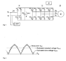
- Fig. 1 presents a PWM frequency converter connected to a 1-phase network to feed a three-phase load. It comprises a mains bridge 10 for rectifying the single-phase alternating voltage U L , N, of the supply network to produce a DC intermediate-circuit direct voltage U DC1 and a load bridge (inverter) 11 for inverting the DC intermediate-circuit direct voltage to produce a variable-frequency three-phase alternating voltage U R , U S , U T , which can be used e.g. to feed a three-phase motor 13.
- the load bridge is a full-wave bridge with a control unit 12 controlling the semiconductor switches V11 - V16 of each phase, each of the switches being connected in inverse-parallel with a free-wheeling diode D11 - D16.
- the mains bridge 10 may be an uncontrolled full-wave bridge with upper and lower arm diodes D1-D4 connected to the phase and free-wheeling arms.
- PWM frequency converters use either an AC inductor L AC as presented in the figure or a DC inductor connected between the mains bridge and the intermediate-circuit capacitor C DC .
- a PWM inverter is used to produce a motor supply voltage whose amplitude and frequency can be adjusted independently of each other.
- the motor may be a cage induction motor or e.g. a permanent-magnet or separately excited synchronous motor.
- the control signals for controlling the semiconductor switches V11 - V16 of the inverter bridge are generated in a PWM modulator by using e.g. sine-triangle comparison or vector modulation, such as space vector PWM.
- Space Vector PWM is a pulse width modulation method especially well suited for digital implementation of the modulation of the inverter of a frequency converter provided with a voltage intermediate circuit, wherein the switching times for the switch positions of the inverter bridge are generally calculated by software. From the switching vectors used during a switching cycle, an output voltage space vector consistent with the reference value is formed as an average value.
- the switching references for the inverter are generated utilizing a measured intermediate-circuit voltage value U dc1 , so the motor supply voltage is consistent with the reference value regardless of small variations in the intermediate-circuit voltage.
- the direct voltage circuit can be implemented by controlling the frequency converter e.g. according to patent specification FI 111201, in which case the capacitor in the direct voltage circuit will not serve as an intermediate energy storage and its voltage in the loaded state will follow the rectified supply network voltage.
- the capacitor is not needed to smooth the intermediate-circuit direct voltage, so it is possible to use capacitor of a considerably lower rating than conventional intermediate-circuit capacitors (typically only about 1 % of the value of a conventional capacitor).
- the present invention relates especially to this type of a modulation method for a pulse width modulator in the inverter section of a frequency converter provided with a small intermediate-circuit capacitor (to generate the switching references for the inverter bridge) in frequency converters fed from a 1-phase supply. It is characteristic of such a device that, in a loaded state of the device, the waveform U dc1 of its intermediate-circuit voltage follows the instantaneous value of the rectified supply network phase voltage relatively accurately. Therefore, in the solution of the invention, the PWM switching references for the semiconductor switches are generated without measurement of the intermediate-circuit voltage, using a simple method of estimating the intermediate-circuit voltage.
- the object of the invention is to simplify the practical implementation of pulse-width modulation, i.e. to simplify the structure of the equipment without substantially compromising on the controllability of the motor.
- the estimate of the intermediate-circuit voltage is a constant voltage.
- an intermediate-circuit voltage value estimated on the basis of the phase angle of the measured mains voltage is used for compensating the modulation of the inverter.
- the information regarding the phase angle of the supply mains voltage which is needed in the method of estimating the intermediate-circuit voltage according to the second embodiment can be produced in a simple way by using a zero voltage detector circuit and a phase-locked loop comprised in it, because the supply mains frequency varies very little.
- the required information regarding the phase angle of the supply mains voltage can be produced on the basis of a motor current measurement.
- a small capacitor C DC is used in the intermediate voltage circuit.
- the intermediate-circuit voltage follows the rectified mains voltage and thus varies greatly.
- the intermediate-circuit voltage U dc1 can theoretically have values between 0 volts and the peak value of the supply phase voltage.
- Fig. 2 presents a diagram of the principle of the situation.
- an estimate is formed for the intermediate-circuit voltage.
- the estimate used may consist of either the constant voltage U dc1C remaining constant and produced on the basis of the load or the intermediate-circuit voltage value U dc1S estimated on the basis of the phase angle of the measured mains voltage.
- the information needed by the control unit regarding the phase angle of the supply network voltage is produced by means of a zero detector circuit VDET detecting the zero point of the voltage, which circuit may contain a phase-locked loop.
- the method of estimating the intermediate-circuit voltage according to the third embodiment utilizes the fact that the motor current shows a strong component having a frequency equaling twice the supply frequency (e.g. 100Hz when the supply frequency is 50Hz).
- the information needed by the control unit regarding the phase angle of the supply network voltage is deduced from the phase angle of this current harmonic, which is seen from the current measurement of the frequency converter.
Landscapes
- Engineering & Computer Science (AREA)
- Power Engineering (AREA)
- Inverter Devices (AREA)
Applications Claiming Priority (2)
| Application Number | Priority Date | Filing Date | Title |
|---|---|---|---|
| FI20040838A FI116647B (fi) | 2004-06-17 | 2004-06-17 | Vaihtosuuntaajan pulssinleveysmodulaattorin ohjaus |
| FI20040838 | 2004-06-17 |
Publications (2)
| Publication Number | Publication Date |
|---|---|
| EP1610451A2 true EP1610451A2 (de) | 2005-12-28 |
| EP1610451A3 EP1610451A3 (de) | 2008-05-21 |
Family
ID=32524513
Family Applications (1)
| Application Number | Title | Priority Date | Filing Date |
|---|---|---|---|
| EP05076337A Withdrawn EP1610451A3 (de) | 2004-06-17 | 2005-06-09 | Steuerung eines Pulsweitenmodulators in einem Wechselrichter |
Country Status (3)
| Country | Link |
|---|---|
| US (1) | US7190597B2 (de) |
| EP (1) | EP1610451A3 (de) |
| FI (1) | FI116647B (de) |
Families Citing this family (9)
| Publication number | Priority date | Publication date | Assignee | Title |
|---|---|---|---|---|
| JP4577062B2 (ja) * | 2005-03-28 | 2010-11-10 | 株式会社デンソー | インバータ制御装置 |
| FI121803B (fi) * | 2005-05-03 | 2011-04-15 | Vacon Oyj | Taajuusmuuttajan valvontajärjestely |
| DE102007052301A1 (de) * | 2007-10-31 | 2009-05-07 | Kostal Industrie Elektrik Gmbh | Photovoltaik-Wechselrichtereinheit |
| WO2014028873A2 (en) * | 2012-08-16 | 2014-02-20 | Perfect Galaxy International Limited | Dc to ac power converter |
| EP2966765A1 (de) * | 2014-07-11 | 2016-01-13 | ABB Technology Oy | Stromwandlersystem mit Gleichstromschienen aus Carbonfasern |
| CN107769259B (zh) * | 2017-12-01 | 2019-08-23 | 北京航空航天大学 | 一种基于离散平均模型的逆变器电流预测控制方法 |
| EP4302392B1 (de) * | 2021-03-04 | 2025-06-18 | SEW-EURODRIVE GmbH & Co. KG | Verfahren zum betreiben eines antriebssystems und antriebssystem zur durchführung des verfahrens |
| CN118677279B (zh) * | 2024-08-23 | 2024-12-10 | 深圳市拓普泰克技术股份有限公司 | 双频控制反激逆变器并网功率因数的方法及控制器 |
| CN118694199B (zh) * | 2024-08-23 | 2024-12-06 | 深圳市拓普泰克技术股份有限公司 | 双电流控制反激逆变器并网功率因数的方法及控制器 |
Family Cites Families (6)
| Publication number | Priority date | Publication date | Assignee | Title |
|---|---|---|---|---|
| JP3265398B2 (ja) * | 1992-01-30 | 2002-03-11 | 株式会社日立製作所 | 直流送電装置の制御装置 |
| DE4428682C2 (de) | 1994-08-12 | 1997-01-23 | Robert Seuffer Gmbh & Co | Verfahren zur Versorgung einer induktiven Last mit sinusförmigem Wechselstrom und Wechselstromsteller hierfür |
| DE19935048A1 (de) | 1999-07-26 | 2001-02-08 | Mulfingen Elektrobau Ebm | System zum Betreiben einer Wechselstromlast, insbesondere eines Wechselstrom-Motors mit Drehzahleinstellung |
| JP4065375B2 (ja) * | 2001-11-20 | 2008-03-26 | 松下電器産業株式会社 | モータ駆動装置及びモータ駆動方法 |
| CN1669208A (zh) * | 2002-07-15 | 2005-09-14 | 皇家飞利浦电子股份有限公司 | 逆变器 |
| EP1496605A1 (de) | 2003-07-07 | 2005-01-12 | Vacon Oyj | Frequenzwandler und sein Steuerungsverfahren |
-
2004
- 2004-06-17 FI FI20040838A patent/FI116647B/fi not_active IP Right Cessation
-
2005
- 2005-06-09 EP EP05076337A patent/EP1610451A3/de not_active Withdrawn
- 2005-06-16 US US11/153,623 patent/US7190597B2/en not_active Expired - Fee Related
Also Published As
| Publication number | Publication date |
|---|---|
| EP1610451A3 (de) | 2008-05-21 |
| US7190597B2 (en) | 2007-03-13 |
| FI116647B (fi) | 2006-01-13 |
| FI20040838A0 (fi) | 2004-06-17 |
| US20050281060A1 (en) | 2005-12-22 |
Similar Documents
| Publication | Publication Date | Title |
|---|---|---|
| CN203675027U (zh) | 无传感器的电动机控制 | |
| US8503205B2 (en) | AC/DC converter with a PFC and a DC/DC converter | |
| EP2346151A1 (de) | Stromwandler | |
| US20140028237A1 (en) | Inverter control apparatus and control method thereof | |
| JPWO2020115800A1 (ja) | 電力変換装置 | |
| CN111149287A (zh) | 功率转换装置 | |
| US7294989B2 (en) | Frequency converter overvoltage protection | |
| CA2598099C (en) | Electric power converter apparatus | |
| KR20080068254A (ko) | 인버터의 입력전류 검출장치 및 그 방법 | |
| KR101911265B1 (ko) | 병렬 운전 모터의 구동 장치 및 이를 포함하는 공기 조화기 | |
| US7190597B2 (en) | Control of an inverter pulse-width modulator | |
| JP2022066920A (ja) | 電力変換システム | |
| JP2911447B2 (ja) | 電動機の制御装置 | |
| JP3773794B2 (ja) | 電力変換装置 | |
| CN100399697C (zh) | 绕线式转子感应电动机的控制器 | |
| EP1511168A2 (de) | Verfahren zur Impulsbreitenmodulation für einen Frequenzumrichter | |
| FI116648B (fi) | Vaihtosuuntaajan pulssinleveysmodulaattorin ohjaus | |
| Krishnaveni et al. | Design and implementation of low cost four switch inverter for BLDC motor drive with active power factor correction | |
| Arunraj et al. | A novel zeta converter with pi controller for power factor correction in induction motor | |
| Parihar et al. | Performance analysis of improved power quality converter fed PMBLDC motor drive | |
| CN101471622B (zh) | 换流器的控制装置 | |
| US20060265160A1 (en) | Arrangement for monitoring a frequency converter | |
| JPH09289776A (ja) | 電源装置のインバータ回路 | |
| KR101911267B1 (ko) | 전력 변환 장치 및 이를 포함하는 공기 조화기 | |
| JP2827986B2 (ja) | 誘導電動機の制御方法及び装置 |
Legal Events
| Date | Code | Title | Description |
|---|---|---|---|
| PUAI | Public reference made under article 153(3) epc to a published international application that has entered the european phase |
Free format text: ORIGINAL CODE: 0009012 |
|
| AK | Designated contracting states |
Kind code of ref document: A2 Designated state(s): AT BE BG CH CY CZ DE DK EE ES FI FR GB GR HU IE IS IT LI LT LU MC NL PL PT RO SE SI SK TR |
|
| AX | Request for extension of the european patent |
Extension state: AL BA HR LV MK YU |
|
| PUAL | Search report despatched |
Free format text: ORIGINAL CODE: 0009013 |
|
| AK | Designated contracting states |
Kind code of ref document: A3 Designated state(s): AT BE BG CH CY CZ DE DK EE ES FI FR GB GR HU IE IS IT LI LT LU MC NL PL PT RO SE SI SK TR |
|
| AX | Request for extension of the european patent |
Extension state: AL BA HR LV MK YU |
|
| 17P | Request for examination filed |
Effective date: 20080701 |
|
| AKX | Designation fees paid |
Designated state(s): AT BE BG CH CY CZ DE DK EE ES FI FR GB GR HU IE IS IT LI LT LU MC NL PL PT RO SE SI SK TR |
|
| STAA | Information on the status of an ep patent application or granted ep patent |
Free format text: STATUS: THE APPLICATION IS DEEMED TO BE WITHDRAWN |
|
| 18D | Application deemed to be withdrawn |
Effective date: 20170103 |