EP1610360A1 - Dummy wafer - Google Patents
Dummy wafer Download PDFInfo
- Publication number
- EP1610360A1 EP1610360A1 EP04724415A EP04724415A EP1610360A1 EP 1610360 A1 EP1610360 A1 EP 1610360A1 EP 04724415 A EP04724415 A EP 04724415A EP 04724415 A EP04724415 A EP 04724415A EP 1610360 A1 EP1610360 A1 EP 1610360A1
- Authority
- EP
- European Patent Office
- Prior art keywords
- carbon fibers
- gpa
- cfrp
- layer
- tensile modulus
- Prior art date
- Legal status (The legal status is an assumption and is not a legal conclusion. Google has not performed a legal analysis and makes no representation as to the accuracy of the status listed.)
- Withdrawn
Links
Images
Classifications
-
- C—CHEMISTRY; METALLURGY
- C08—ORGANIC MACROMOLECULAR COMPOUNDS; THEIR PREPARATION OR CHEMICAL WORKING-UP; COMPOSITIONS BASED THEREON
- C08J—WORKING-UP; GENERAL PROCESSES OF COMPOUNDING; AFTER-TREATMENT NOT COVERED BY SUBCLASSES C08B, C08C, C08F, C08G or C08H
- C08J5/00—Manufacture of articles or shaped materials containing macromolecular substances
- C08J5/04—Reinforcing macromolecular compounds with loose or coherent fibrous material
- C08J5/0405—Reinforcing macromolecular compounds with loose or coherent fibrous material with inorganic fibres
- C08J5/042—Reinforcing macromolecular compounds with loose or coherent fibrous material with inorganic fibres with carbon fibres
-
- H—ELECTRICITY
- H10—SEMICONDUCTOR DEVICES; ELECTRIC SOLID-STATE DEVICES NOT OTHERWISE PROVIDED FOR
- H10P—GENERIC PROCESSES OR APPARATUS FOR THE MANUFACTURE OR TREATMENT OF DEVICES COVERED BY CLASS H10
- H10P14/00—Formation of materials, e.g. in the shape of layers or pillars
- H10P14/20—Formation of materials, e.g. in the shape of layers or pillars of semiconductor materials
-
- H—ELECTRICITY
- H10—SEMICONDUCTOR DEVICES; ELECTRIC SOLID-STATE DEVICES NOT OTHERWISE PROVIDED FOR
- H10P—GENERIC PROCESSES OR APPARATUS FOR THE MANUFACTURE OR TREATMENT OF DEVICES COVERED BY CLASS H10
- H10P72/00—Handling or holding of wafers, substrates or devices during manufacture or treatment thereof
- H10P72/06—Apparatus for monitoring, sorting, marking, testing or measuring
- H10P72/0606—Position monitoring, e.g. misposition detection or presence detection
-
- C—CHEMISTRY; METALLURGY
- C08—ORGANIC MACROMOLECULAR COMPOUNDS; THEIR PREPARATION OR CHEMICAL WORKING-UP; COMPOSITIONS BASED THEREON
- C08J—WORKING-UP; GENERAL PROCESSES OF COMPOUNDING; AFTER-TREATMENT NOT COVERED BY SUBCLASSES C08B, C08C, C08F, C08G or C08H
- C08J2363/00—Characterised by the use of epoxy resins; Derivatives of epoxy resins
Definitions
- the present invention relates to a dummy wafer that is used in a process for manufacturing a semiconductor such as a semiconductor integrated circuit and a semiconductor memory.
- processing known as dummy processing wherein various processing is performed using a dummy wafer on which no actual IC pattern is formed, has been performed for the operation test of, for example, a plasma etching apparatus, a CVD apparatus, a sputtering apparatus or the like; the number adjustment of wafers in batch process; the countermeasure against the loading effect; or the like.
- a plasma etching apparatus such as a plasma CVD apparatus
- a dummy wafer has also been used for protecting a substrate-supported electrode from the plasma.
- Further object of the present invention is to provide a dummy wafer that has substantially uniform flexural rigidity and is excellent in planarity, preferably even if it is very thin below the SEMI standard.
- the following dummy wafer is provided:
- X 1 to X 2 that indicates a range of numeric values means the range between X 1 and X 2 including both X 1 and X 2 .
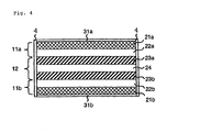
- 1 wafer substrate; 2a, 2b: principal surface, 3:end surface, 4: end surface coating layer, 5a, 5b:principal surface coating layer, 11a, b: skin layer, 12: core layer, 21a,b: CFRP layer containing PAN-based carbon fibers having a tensile modulus of 230 GPa, 22a, b: CFRP layer containing pitch-based carbon fibers having a tensile modulus of 800 GPa, 23a, b: glass-fiber reinforced plastic layer, 24: CFRP layers containing pitch-based carbon fibers having a tensile modulus of 600 GPa, 31a, b:carbon-fiber cloth layer.
- the shape of the dummy wafer of the present invention is normally the same shape as the prime wafer used in an actual semiconductor product.
- the shapes of prime wafers are specified in, for example, the SEMI (Semiconductor Equipment and Materials International) Standard. The same applies to the dimensions of dummy wafers.
- CFRP carbon fiber reinforced plastic
- CFRP can be obtained by impregnating a matrix resin into reinforcing fibers mainly composed of carbon fibers to form a prepreg, laminating the prepregs as required, and curing the matrix resin.
- thermosetting resin a thermosetting resin, a thermoplastic resin, and a mixture of two or more of these resins can be used; and in particular, a thermosetting resin can be preferably used.
- thermosetting resins such as epoxy resins, aramid resins, bismaleimide resins, phenolic resins, furan resins, urea resins, unsaturated polyester resins, epoxy acrylate resins, diallyl phthalate resins, vinyl ester resins, thermosetting polyimide resins, and melamine resins can be used; and in particular, an epoxy resin can be preferably used.
- thermoplastic resin resins such as nylon resins, liquid crystalline aromatic polyamide resins, polyester resins, liquid crystalline aromatic polyester resins, polypropylene resins, polyether sulfone resins, polyphenylene sulfide resins, polyether ether ketone resins, polysulfone resins, polyvinyl chloride resins, vinylon resins, aramid resins, and fluorocarbon resins can be used.
- the matrix resin has a viscosity of preferably 5,000 poise to 1,000,000 poise, more preferably 10,000 poise to 1,000,000 poise, and further preferably 50,000 poise to 150,000 poise at 25°C; and preferably 1,000 poise to 30,000 poise, and more preferably 1,000 poise to 10,000 poise at 50°C.
- the viscosity at 25°C of the matrix resin for producing CFRP be not higher than 1,000,000 poise, the hardening of the prepreg and the lowering of tackiness can be excellently prevented; and by making the viscosity be not lower than 5,000 poise, the difficulty in correcting the lamination of the prepreg due to strong tackiness so that the once bonded prepreg when the prepreg is laminated is difficult to peel off can be excellently prevented.
- the viscosity at 50°C be not lower than 1,000 poise, the impregnation of the resin is easy and the increase in resin flow during shape forming can be excellently prevented; and by making the viscosity at 50°C be not higher than 30,000 poise, the decrease in resin flow during shape forming and the inferior impregnation of the resin can be excellently prevented.
- the quantity of the matrix resin contained in the prepreg is preferably selected to be within a range from 20% by mass to 50% by mass to the total quantity of the reinforcing fibers and the matrix resin, more preferably within a range from 25% by mass to 45% by mass, regardless of whether optional components, such as a filler, are contained or not.
- the heat resistant temperature of a dummy wafer can be elevated to 230°C, a dummy wafer having extremely favorable composite properties and excellent heat resistance, and substantially free of out gas can be produced.
- Out gas is a gas that comes out of the resin, and it may be a contamination source of the semiconductor manufacturing process.
- epoxy resin composition consisting of one or the combination of two or more selected from bisphenol-A epoxy resin, phenol novolak epoxy resin, glycidyl amine epoxy resin and bisphenol-F epoxy resin, and diaminodiphenyl sulfone is preferable.
- a bisphenol-A epoxy resin that has a liquid form at 20°C is preferably used as the bisphenol-A epoxy resin.
- a liquid form at 20°C means that the viscosity of the resin is within a range of 1 poise to 1000 poise, preferably 10 poise to 500 poise at this temperature.
- Specific examples of bisphenol-A epoxy resins that have a liquid form at 20°C include bisphenol-A epoxy resins marketed under the trade names or product numbers of Epotohto YD128 and YD134 (manufactured by Tohto Kasei Co., Ltd.), and Epikote 828 and 834 (manufactured by Yuka Shell Epoxy Co., Ltd.).
- the content of the bisphenol-A epoxy resin in the epoxy resin composition is selected to be preferably within a range of 20 parts by mass to 40 parts by mass to 100 parts by mass of the total quantity of epoxy resins, more preferably 25 parts by mass to 35 parts by mass.
- the content be 40 parts by mass or lower, it is possible to excellently prevent the difficulty in handling of the prepreg when the prepreg is formed due to the elevation of tackiness, and it is possible to excellently prevent the lowering of the composite properties when a composite material is formed, and the lowering of heat resistance and moisture resistance.
- phenol novolak epoxy resin a phenol novolak epoxy resin that has a viscosity at 52°C of 10 poise to 3000 poise, and more preferably 10 poise to 2000 poise, is preferably used.
- usable resins include phenol novolak epoxy resins marketed under the trade names or product numbers of Epikote 152 and 154 (manufactured by Yuka Shell Epoxy Co., Ltd.), DEN 431, 438 and 439 (manufactured by Dow Chemical Co.), and Phenotohto YP 50 and YDPN 638 (manufactured by Tohto Kasei Co., Ltd.).
- the use thereof can improve the composite properties, heat resistance and moisture resistance of a composite material.
- the content of the phenol novolak epoxy resin in the epoxy resin composition is selected to be preferably within a range of 40 parts by mass to 60 parts by mass to 100 parts by mass of the total quantity of epoxy resins, more preferably 45 parts by mass to 55 parts by mass.
- glycidyl amine epoxy resin 4-functional glycidyl amine epoxy resin is preferable, and more specifically, tetraglycidyl diaminodiphenylmethane is preferable.
- This type of 4-functional glycidyl amine epoxy resin is marketed under the trade names or product numbers such as Epotohto YH 434 (manufactured by Tohto Kasei Co., Ltd.), ELM 434 (manufactured by Sumitomo Chemical Co., Ltd.), and Epikote 604 (manufactured by Yuka Shell Epoxy Co., Ltd.).
- Epotohto YH 434 manufactured by Tohto Kasei Co., Ltd.
- ELM 434 manufactured by Sumitomo Chemical Co., Ltd.
- Epikote 604 manufactured by Yuka Shell Epoxy Co., Ltd.
- the bisphenol-F epoxy resin is a condensation reaction product of bisphenol-F with epichlorohydrin.
- the bisphenol-F epoxy resin whose epoxy equivalent is within a range of 155 to 190, and whose viscosity at 25°C is within a range of 4.0 poise to 4.5 poise is preferably used.
- Examples of commercially available products include Epikote 807 (manufactured by Yuka Shell Epoxy Co., Ltd.), Epotohto YDF 170 (manufactured by Tohto Kasei Co., Ltd.), and Epiclon 830 (manufactured by Dainippon Ink & Chemicals, Inc.).
- the blending quantity thereof is selected from ranges preferably 50 parts by mass or less, more preferably 40 parts by mass or less, and further preferably 15 parts by mass or less to 100 parts by mass of the total quantity of epoxy resins.
- a phenoxy resin can be used, and typically, the phenoxy resin represented by the following formula or the epoxy-modified phenoxy resin thereof can be used.
- phenoxy resins those marketed under the trade names or product numbers of YP 50 (manufactured by Tohto Kasei Co., Ltd.), and PKHH (manufactured by Phenoxy Associates) can be used.
- the content thereof can be selected to be preferably within a range of 5 parts by mass to 20 parts by mass to 100 parts by mass of the total quantity of epoxy resins, more preferably 7 parts by mass to 18 parts by mass.
- diaminodiphenyl sulfone 4,4'-diaminodiphenyl sulfone and 3,3'-diaminodiphenyl sulfone can be used, and 4,4'-diaminodiphenyl sulfone is preferable.
- This is a component that functions as a curing agent, and for example, Seikacure-S (trade name, manufactured by Wakayama Kasei Kogyo) can be preferably used.
- the Seikacure-S is in the form of powder having an average particle diameter of 8 ⁇ m to 9 ⁇ m.
- the quantity is selected from a range of preferably 30 parts by mass to 50 parts by mass to 100 parts by mass of the total quantity of epoxy resins in the epoxy resin composition, more preferably 35 parts by mass to 45 parts by mass.
- the quantity is selected from a range of preferably 30 parts by mass to 50 parts by mass to 100 parts by mass of the total quantity of epoxy resins in the epoxy resin composition, more preferably 35 parts by mass to 45 parts by mass.
- diaminodiphenyl sulfone is in the form of fine particles that have diameters from 0.01 ⁇ m to 10 ⁇ m, and is dispersed in the above-described epoxy resin composition.
- a publicly known dispersing method wherein appropriate means for kneading such as a kneader and a 3-roll machine is used can be adopted.
- an epoxy resin other than that described above, a toughning agent, fillers, coloring agent, etc. can be blended as required within the range not to damage the properties.
- Fillers include inorganic fillers, such as mica, alumina, talc, fine silica powder, wollastonite, sepiolite, basic magnesium sulfate, zinc powder, aluminum powder, clay, calcium carbonate, titanium dioxide, calcium sulfate, barium sulfate, and carbon black; and organic fillers such as Teflon powder, polyethylene powder, polyamide powder, and EVA (ethylene-vinyl acetate copolymer) powder.
- the quantity of the added filer in the above-described epoxy resin composition can be normally about 5 parts by mass to 60 parts by mass to 100 parts of the total quantity of epoxy resins.
- Coloring agents that can be used include azo pigments, phthalocyanine-based pigments, quinacridone-based pigments, anthraquinone-based pigments and the like as organic pigments; and titanium dioxide, chrome yellow, cobalt violet, colcothar as inorganic pigments.
- a curing agent other than the above-described diaminodiphenyl sulfone or a curing accelerator can be blended as required.
- the curing agents include diaminodiphenyl sulfone, diaminodiethyl benzene or the like; and examples of curing accelerators include boron trifluoride monoethylamine complex, boron trichloride monoethylamine complex.
- the tensile modulus of the carbon fiber to be used is preferably 400 GPa or more, more preferably 500 GPa or more, and further preferably 600 GPa or more.
- the tensile modulus of the carbon fiber to be used is preferably not more than 1000 GPa, more preferably not more than 900 GPa, and further preferably not more than 800 GPa.
- a pitch-based carbon fiber can be preferably used as the carbon fiber that has such a tensile modulus.
- the use of the pitch-based carbon fiber is also preferable in view of the costs.
- the pitch-based carbon fiber is a carbon fiber obtained from pitch and the PAN-based carbon fiber is a carbon fiber obtained from polyacrylonitrile.
- carbon fibers can be used alone as the reinforcing fibers for CFRP, carbon fibers can also be used in combination of with glass fibers, aramid fibers, stainless-steal fibers, copper fibers, nickel fibers, titanium fibers, tungsten fibers, silicon carbide fibers, alumina fibers, titanium carbide fibers, boron nitride fibers, or other fibers.
- the form of the above-described reinforcing fibers is not specifically limited, but one-dimensional reinforcement, two-dimensional reinforcement, three-dimensional reinforcement, or random reinforcement can be appropriately selected depending on purposes.
- the reinforcing fibers can be used as short fibers, woven fabrics, non-woven fabrics, unidirectional material, two-dimensional fabrics, three-dimensional fabrics, or the like; and more specifically the lamination of materials, such as felt, matt, knot cloth, Warif, quasi-isotropic material, plain weave, satin fabric, twill weave, mock leno weave and leno weave can also be used.
- CFRP can be manufactured by normally known methods.
- the reinforcing fibers processed in the form as described above is impregnated with a thermosetting resin as a matrix resin to form prepreg, and CFRP can be manufactured by further laminating, and curing and shape forming, that is, by cure-shape-forming the prepregs.
- the method to impregnate the above-described reinforcing fibers with a matrix resin can be appropriately adopted.
- a thermosetting resin is used as the matrix resin
- a method wherein the reinforcing fibers is impregnated with the resin heated normally to 60°C to 90°C, known as a hot-melt method can be preferably adopted.
- the content of the matrix resin in the manufactured prepreg is preferably within a range of 20% by mass to 50% by mass, more preferably 25% by mass to 45% by mass to the total quantity of the reinforcing fibers and the matrix resin.
- a filler can be added to the matrix resin as desired, and examples of such fillers include mica, alumina, talc, fine silica powder, wollastonite, sepiolite, basic magnesium sulfate, calcium carbonate, polytetrafluoroethylene powder, zinc powder, aluminum powder, and fine organic particles, such as fine acrylic particles, fine epoxy resin particles, fine polyamide particles, and fine polyurethane particles.
- the prepreg is finally shaped into CFRP.
- the shaping methods an autoclave shaping method, a sheet rolling shaping method and the like can be used.
- the prepreg can be laminated to be a shape suitable for a dummy wafer, and heated and cured in an autoclave or by a press normally at 110°C to 150°C for 30 minutes to 3 hours to form CFRP.
- the resulting CFRP can have a stable quality and containing few voids.
- the heating temperature is 150°C to 200°C
- the curing time is 30 minutes to 2 hours.
- the resulting CFRP can further be processed into a shape suitable for the dummy wafer using machining or the like.
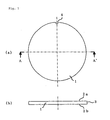
- Figure 1 is a schematic view showing an embodiment of a dummy wafer of the present invention, (a) is a top view and (b) is an A-A' sectional view.
- the dummy wafer is consisits of a wafer substrate 1.
- the wafer substrate is plate-shaped, specifically disc-shaped, and has a principal surface 2a on the upper surface side, a principal surface 2b on the lower surface side, and an end surface 3, and has a notch 4 for alignment.
- the dummy wafer is not necessarily consists of the wafer substrate alone, but can include, for example, a coating layer for desired purposes, such as dust-generation prevention and scratch prevention.
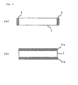
- the dummy wafer shown in Figure 2 (a) has a end surface coating layer 4 for coating the end surface on the end surface of the wafer substrate 1.
- the dummy wafer shown in Figure 2 (b) has principal surface coating layers 5a and 5b for coating each principal surface on the principal surfaces of the wafer substrate 1.
- the coating layers can be formed, for example, of a resin. When a notch is formed by machining, the processed surface can be provided with a coating layer.
- the wafer substrate can consists of a plate-shaped carbon fiber reinforced plastic (CFRP), or may be a plate-shaped laminate, wherein, for example, layers consists of a plurality of CFRPs (hereafter, a layer consists of CFRP is referred to as a CFRP layer) having the same shape as the intended wafer substrate but being thinner are joined and laminated in the thickness direction.
- CFRP layer a layer consists of CFRP
- the wafer substrate can also have another layer having the same shape as the wafer substrate but being thinner in addition to a CFRP layer.
- a layer consisting of a resin, and a layer consisting of a fiber reinforced plastic wherein carbon fibers are not major reinforcing fibers are exemplified.
- the wafer substrate having a plurality of CFRP layers may be a wafer substrate wherein all the CFRP layers of the same shape, size and material are laminated in the same orientation, it is not necessarily required to have such a constitution.
- One or more of thickness, material and orientation may be different in the plurality of CFRP layers.
- CFRP layers of the same shape, size and material may be laminated in different orientations.
- CFRP has a character that it is difficult to bend in the orientation direction of carbon fibers, and easy to bend in a direction perpendicular thereto.
- Different orientations of multiple CFRP layers are preferable in that the isotropy of the deflection of the wafer substrate wherein these CFRP layers are laminated is improved.
- the wafer substrate has multiple one-dimensionally reinforced CFRP layers (this layer is a layer consisting of a carbon fiber reinforced plastic made of a cured and shaped product of unidirectional prepreg having carbon fibers oriented in one direction) and the tensile modulus of carbon fibers in a part of layers among the multiple one-dimensionally reinforced CFRP layers is higher than the tensile modulus of carbon fibers in the other layers.
- this layer is a layer consisting of a carbon fiber reinforced plastic made of a cured and shaped product of unidirectional prepreg having carbon fibers oriented in one direction
- the tensile modulus of carbon fibers in a part of layers among the multiple one-dimensionally reinforced CFRP layers is higher than the tensile modulus of carbon fibers in the other layers.
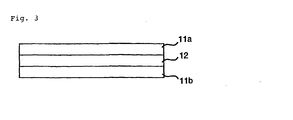
- a wafer substrate having skin layers 11 a and 11 b disposed on two principal surface sides, respectively, and a core layer 12 interposed between them is schematically shown.
- the properties of the skin layer rather than the core layer are important, and in particular, the properties of the outermost layer are important.
- the modulus of elasticity of laminated carbon fibers it is further preferable to make the modulus of elasticity of laminated carbon fibers to be different, and it is preferable to use carbon fibers having medium or high modulus of elasticity for the outermost layer of the skin layer (the reinforcing direction, that is the orientation direction of carbon fibers, in the outermost layer is made the reference direction of the dummy wafer), and carbon fibers having higher modulus of elasticity than the outermost layer for the inner layer (it is further preferable that this layer is oriented in a direction different from the reference direction, for example, of 90°).
- the reinforcing direction that is the orientation direction of carbon fibers, in the outermost layer is made the reference direction of the dummy wafer
- this layer is oriented in a direction different from the reference direction, for example, of 90°.
- counter-clockwise directions are indicated as + directions.
- a preferable example of wafer substrate is a dummy wafer wherein the wafer substrate has two skin layers each located on principal surface side, and a core layer located between said two skin layers; both of the two skin layers have a plurality of the one-dimensionally reinforced CFRP layers; when the orientation direction of carbon fibers in one of the two outermost CFRP layers, which are one-dimensionally reinforced CFRP layers located closest to the principal surface side in each of the two skin layers, is made to be a reference direction, the orientation direction of carbon fibers in the other outermost CFRP layer falls within an angle range from -20° to +20° with respect to the reference direction; the tensile modulus of carbon fibers in both the two outermost CFRP layers is 200 GPa to 600 GPa; both the two skin layers have a one-dimensionally reinforced CFRP layer containing carbon fibers oriented in an angle range from +75° to +90° with respect to the reference direction and having a tensile modulus of 400 GPa to 1000 GPa and higher than the tens
- Flexural rigidity is the product obtained by multiplying the flexural modulus of the layer by the cube of the distance from the neutral axis and by the thickness of the layer.
- the outermost layer is most easily influenced by the distance from the neutral axis.
- the thickness of each of the two skin layers is preferably 10% to 45% the total thickness of the two skin layers and the core layer.
- a dummy wafer comprising a wafer substrate including a carbon fiber reinforced plastic, wherein the wafer substrate has two skin layers each located on principal surface side, and a core layer located between the two skin layers; both of the two skin layers have a plurality of one-dimensionally reinforced CFRP layers, said one-dimensionally reinforced CFRP layer being a layer consisting of carbon fiber reinforced plastic consisting of a cured and shaped product of a unidirectional prepreg in which carbon fibers are oriented in one direction; when the orientation direction of carbon fibers in one of the two outermost CFRP layers, which are one-dimensionally reinforced CFRP layers located closest to the principal surface side in each of said two skin layers, is made to be a reference direction, the orientation direction of carbon fibers in the other outermost CFRP layer falls within an angle range from -20° to +20° with respect to the reference direction; the tensile modulus of carbon fibers in both the two outermost CFRP layers is 200 GPa to 600 GPa; both the two skin layers have
- At least one of the two skin layers further has a one-dimensionally reinforced CFRP layer containing carbon fibers oriented in an angle range from +30° to +60° with respect to the reference direction and having a tensile modulus 1.5 times to 3.0 times that of carbon fibers of the outermost CFRP layer contained in the skin layer, and/or a one-dimensionally reinforced CFRP layer containing carbon fibers oriented in an angle range from -30° to -60° with respect to the reference direction and having a tensile modulus 1.5 times to 3.0 times that of carbon fibers of the outermost CFRP layer contained in the skin layer.
- the dummy wafer of the above-described configurations it is preferable that the dummy wafer further has a carbon fiber cloth layer on each of the principal surfaces in the view point of preventing the front layer from peeling off in machining.
- the wafer substrate can be manufactured, for example, by machining a plate-like CRFP to form a desired shape, such as a circle.
- the wafer substrate can be manufactured by joining multiple plate-like CFRPs as required to form an integrated plate-like member having a desired thickness, and machining it to form a desired shape.
- the wafer substrate can be manufactured by joining one or more plate-like CFRPs in combination with a plate-like member made of other material to form an integrated plate-like member, and machining it to form a desired shape.
- SEMI M1.14-95 specifies the guideline of a mirror-surface single crystalline silicon wafer of a diameter of 300 mm to 400 mm.
- the required conditions for dimensions and tolerance described in this guideline are summarized in Table 1.
- the shape and size of the dummy wafer used in place of such a silicon wafer should be the same as the shape and size of the silicon wafer, the thickness thereof is as thin as 0.8 mm as shown in Table 1, and in some cases, further thin wafers as 0.5 mm are required.
- CFRP CFRP
- the processed surface is coated by a resin that has resistance to polar solvents, and cures at a low temperature of 70°C or lower (hereafter referred to as a coating resin).
- a coating resin a resin that has resistance to polar solvents, and cures at a low temperature of 70°C or lower
- the term "processed surface” used herein means the portion on which carbon fibers in CFRP are exposed by processing, such as machining, and specifically, a cut surface, a polished surface, a rounded surface, a holed surface, a thinned surface and the like are included.
- the end surface of a wafer substrate is a processed surface formed by machining, it is preferable that the end surface is provided with a coating layer as Figure 2 (a) shows.
- this coating has the effect of protecting the end surface, such as the prevention of scratches.
- coating resins include an acrylic resin, an ultraviolet-curing epoxy resin, an epoxy resin that cures at room temperature to medium temperature, a moisture-curing silicone resin, and the mixture of two or more resins selected from these resins.
- the mixing mass ratio of two kinds of resins selected from these resins is preferably 1:0.05 to 0.05:1.
- Resistance of a resin against a polar solvent means that even if the resin-applied surface is wiped with cloth soaked by a polar solvent, the applied surface is not easily dissolved, swollen, or does not become sticky, and dirt or dust derived from carbon fibers, such as fine carbon particles does not substantially fly from the dummy wafer, and furthermore, the cloth used for wiping the resin-applied surface is not substantially contaminated by fine carbon particles or the like.
- a polar solvent is an acetone-based or alcohol-based solvent or the like, for example, acetone, diethyl ketone, methyl ethyl ketone, methanol, ethanol, isopropyl alcohol, the mixture thereof and the like.
- acrylic resins include polyester acrylate, urethane acrylate, polyether acrylate, epoxy acrylate, polybutadiene acrylate, silicone acrylate, acryl acrylate, the mixture thereof and the like.
- the resin By adding a peroxide for room-temperature curing or a catalyst for ultraviolet curing to the coating resin, the resin can be cured at room temperature or by ultraviolet irradiation.
- the epoxy resin that cures at room temperature to medium temperature means an epoxy resin that cures normally at 10°C to 90°C, preferably at 20°C to 80°C. If the resin cures at 90°C or below, the thermal deformation of CFRP members can be prevented.
- an epoxide reaction product of an alicyclic amine and/or an aromatic amine with an epoxy resin can be preferably used.
- ultraviolet-curing epoxy resin for example, a liquid bis-phenol epoxy resin, an alicyclic epoxy resin, or a mixture thereof can be used.
- An aromatic diazonium salt, an aromatic iodonium salt, an aromatic sulfonium salt, a metallocene compound, or a mixture thereof can be added to the ultraviolet-curing epoxy resin as a curing catalyst.
- an alkyd-modified silicone resin an epoxy-modified silicone resin, a moisture-curing alcohol silicone resin, a moisture-curing oxime silicone resin, or an addition-reaction silicone resin can be used.
- the moisture-curing alcohol silicone resin or the moisture-curing oxime silicone resin are preferably used.
- moisture-curing alcohol-type silicone resin for example, SR 2410, SR 2406, SR 2420, and SR 2416 (trade names, manufactured by Dow Corning Toray Silicone Co., Ltd.), and KE 4895 (trade name, manufactured by Shin-Etsu Chemical Co., Ltd.) can be used.
- dibutyl tin diacetate, dibutyl tin dilaurate, or a mixture thereof can be used as the curing catalyst for the above-described moisture-curing alcohol silicone resin.
- moisture-curing oxime silicone resin for example, SR 2405 and SR 2411 (trade names, manufactured by Dow Corning Toray Silicone Co., Ltd.), and KE 445 (trade name, manufactured by Shin-Etsu Chemical Co., Ltd.) can be used.
- dibutyl tin diacetate, dibutyl tin dilaurate, or a mixture thereof can be used as in the case of the moisture-curing alcohol silicone resin.
- a coating method a method wherein a coating resin diluted to 5 parts by mass to 60 parts by mass with a solvent is applied onto the processed surface of a dummy wafer, and the applied resin is heated and cured at 70°C or below, is preferably used.
- a dummy wafer having resistance against polar solvents, and whose processed surface is coated with a resin that cured at a low temperature of 70°C or below (coating resin) can be obtained.
- the concentration of the coating resin diluted with a solvent be 5 parts by mass or above, the thinning of the coating film obtained by applying the diluted coating resin onto the processed surface can be prevented; and by making it be 60 parts by mass or below, the occurrence of concavity and convexity on the surface of the member due to uneven coating after the applied coating resin has cured can be excellently prevented.
- the method for applying the coating resin is not specifically limited. Any methods can be appropriately used as long as the coating resin can be coated on the processed surface of the dummy wafer, and brushing, spraying, roll-coating or the like can be adopted.
- the thickness of the coating layer obtained by applying and curing the coating resin diluted with a solvent can be, for example, 5 ⁇ m to 30 ⁇ m.
- the thickness can be 30 ⁇ m or below, the consumption of a long time for drying can be prevented, and dripping or unevenness can be excellently prevented.
- the thickness can be 5 ⁇ m or above, the effect of coating can be well obtained.
- the curing temperature of the above-described coating resin is preferably 20°C to 70°C, and by curing at 70°C or below, the warp or deformation of the dummy wafer due to heat can be excellently prevented during curing.
- a dummy wafer shown in Figure 4 was fabricated using the procedures described below:
- Epotohto YD 128 (trade name, manufactured by Tohto Kasei Co., Ltd.)
- phenol novolak epoxy resin 50 parts by mass of Epotohto YDPN 638 (trade name, manufactured by Tohto Kasei Co., Ltd.)
- Phenotohto YP 50 (trade name, manufactured by Tohto Kasei Co., Ltd.) were mixed at 200°C for 1.5 hours, and cooled to 90°C.
- Epotohto YH 434 (trade name, manufactured by Tohto Kasei Co., Ltd.), which is a glycidyl-amine epoxy resin
- DDS 4,4'-diaminodiphenyl sulfone
- a skin layer having a thickness of 0.156 mm was fabricated by laminating one unidirectional prepreg sheet obtained by drawing and aligning pitch-based carbon fibers having a tensile modulus of 800 GPa in one direction and impregnating them with the epoxy resin composition obtained in the above (1) (fiber mass per unit area: 70 g/m 2 , resin content: 38% by mass, thickness: 0.067 mm) so that the reinforcing direction thereof becomes 90° direction with respect to the reference direction of the dummy wafer; and one unidirectional prepreg sheet obtained by drawing and aligning PAN-based carbon fibers having a tensile modulus of 230 GPa in one direction and impregnating them with the epoxy resin composition obtained in the above (1) (fiber mass per unit area: 85 g/m 2 , resin content: 38% by mass, thickness: 0.089 mm) (the reinforcing direction becomes the reference direction of the dummy wafer, i.e.
- the prepreg sheets containing the pitch-based carbon fibers become CFRP layers 22a and 22b containing pitch-based carbon fibers
- the prepreg sheets containing the PAN-based carbon fibers become CFRP layers 21 a and 21 b containing PAN-based carbon fibers (these become the outermost CFRP layer).
- One of the unidirectional prepreg sheets that had pitch-based carbon fibers of a tensile modulus of 600 GPa was first laminated so that the reinforcing direction thereof became +45° with respect to the reference direction of the dummy wafer, and then, one of the above-described unidirectional prepreg sheets that had pitch-based carbon fibers of a tensile modulus of 600 GPa was laminated so that the reinforcing direction thereof became -45° with respect to the reference direction of the dummy wafer. Further thereon, the above-described glass-fiber woven prepreg sheet was laminated so that one of the reinforcing directions thereof agreed with the reference direction of the dummy wafer.
- one of the unidirectional prepreg sheets that had pitch-based carbon fibers of a tensile modulus of 600 GPa was first laminated so that the reinforcing direction thereof became -45° with respect to the reference direction of the dummy wafer, and then, one of the above-described unidirectional prepreg sheets that had pitch-based carbon fibers of a tensile modulus of 600 GPa was laminated so that the reinforcing direction thereof became +45° with respect to the reference direction of the dummy wafer; and the laminate was cured in an autoclave to fabricate a core layer of a thickness of 0.258 mm.
- the percentage by volume of the cured and shaped product of the former prepregs, in which the pitch-based carbon fibers were used, in the core layer was 74%, and the balance 26% was the cured and shaped product of the latter prepreg in which glass fibers were used.
- a moisture-curing alcohol silicone coating agent SR 2419 (trade name, manufactured by Dow Corning Toray Silicone Co., Ltd., resin content: 20 parts by mass, solvent: ligroin) was applied to the above-described processed surface using a brush. After drying the applied silicone coating agent, it was cured in a drying furnace at 50°C for 1 hour to further accelerate the cure of the coating agent to form a coating layer 4 to obtain a dummy wafer.
- the applied surface was sufficiently wiped using clean cloth (polyester knit) free of duct soaked with ethanol, and no contamination of the coating-resin applied surface of the end portion of the dummy wafer and the clean cloth was observed.
- Strip test specimens of 20 mm wide ⁇ 80 mm long ( ⁇ 0.770 mm thick) were cut out of the above described dummy wafer. Two kinds of cutting directions of the test specimens were a direction wherein the reference direction of the dummy wafer agreed to the length direction of the above described test specimen (0° test specimen), and a direction wherein the 90° to the reference direction of the dummy wafer agreed to the length direction of the above described test specimen (90° test specimen).
- flexural moduli were measured by the three-point flexural test. The distance between fulcrums in the three-point flexural test was 60 mm.
- Example 2 shows that the dummy wafer in Example 1 had isotropy, wherein difference in flexural moduli between the reference direction and 90° to the reference direction was small.
- the thicknesses of the dummy wafer were measured.
- the number of points where the thicknesses were measured was 121.
- the difference between the maximum thickness and the minimum thickness was 0.02 mm, and the dummy wafer of Example 1 had an even thickness.
- a graphite plate of substantially the same shape as the dummy wafer (a mass of 1 kg) was placed on the above-described dummy wafer, and was subjected to 50 cycles of thermal shock tests wherein the dummy wafer was placed in an electric furnace in the atmosphere at 200°C for 10 minutes, and thereafter taken out and cooled in the air for 10 minutes at room temperature.
- no abnormality such as warp and delamination occurred.
- unidirectional prepreg sheets There were used three kinds of unidirectional prepreg sheets: a unidirectional prepreg sheet obtained by drawing and aligning pitch-based carbon fibers having a tensile modulus of 500 GPa in one direction and impregnating them with the epoxy resin composition obtained in the above (1) (fiber mass per unit area: 50 g/m 2 , resin content: 38% by mass, thickness: 0.048 mm); a unidirectional prepreg sheet obtained by drawing and aligning pitch-based carbon fibers having a tensile modulus of 800 GPa in one direction and impregnating them with the epoxy resin composition obtained in the above (1) (fiber mass per unit area: 50 g/m 2 , resin content: 38% by mass, thickness: 0.048 mm); and a unidirectional prepreg sheet obtained by drawing and aligning PAN-based carbon fibers having a tensile modulus of 230 GPa in one direction and impregnating them with the epoxy resin composition obtained in the above (1) (fiber mass per unit area
- the unidirectional prepreg sheets having pitch-based carbon fibers of a tensile modulus of 500 GPa, and the unidirectional prepreg sheets having pitch-based carbon fibers of a tensile modulus of 800 GPa were used; as a core layer, the unidirectional prepreg sheets having PAN-based carbon fibers of a tensile modulus of 230 GPa were used; and after laminating unidirectional prepreg sheets used for the skin layers and the core layer, the wafer substrate having the skin layers and the core layer was integrally shaped.
- one unidirectional prepreg sheet having pitch-based carbon fibers of a tensile modulus of 500 GPa (the reinforcing direction thereof becomes the reference direction of the dummy wafer) was disposed, and thereon, unidirectional prepreg sheets having pitch-based carbon fibers of a tensile modulus of 800 GPa were laminated so that the reinforcing direction of each sheet becomes sequentially 90°, +45°, and -45° to the reference direction of the dummy wafer, respectively.
- one unidirectional prepreg sheet having PAN-based carbon fibers of a tensile modulus of 230 GPa was laminated thereon so that the reinforcing direction thereof becomes the reference direction of the dummy wafer; two unidirectional prepreg sheets each having PAN-based carbon fibers of a tensile modulus of 230 GPa were laminated thereon so that the reinforcing directions thereof are perpendicular to the reference direction of the dummy wafer; and further one unidirectional prepreg sheet having PAN-based carbon fibers of a tensile modulus of 230 GPa was laminated thereon so that the reinforcing direction thereof becomes the reference direction of the dummy wafer.
- unidirectional prepreg sheets each having pitch-based carbon fibers of a tensile modulus of 800 GPa were laminated so that the reinforcing direction of each sheet becomes sequentially -45°, +45°, and 90° to the reference direction of the dummy wafer, respectively; and finally thereon, one unidirectional prepreg sheet having pitch-based carbon fibers of a tensile modulus of 500 GPa was laminated so that the reinforcing direction thereof becomes the reference direction of the dummy wafer.
- the laminated constitution of the dummy wafer according to Example 2 has, in the order from one principal surface, (500 GPa, 0°, one layer), (800 GPa, 90°, one layer), (800 GPa, +45°, one layer), (800 GPa, -45°, one layer), (230 GPa, 0°, one layer), (230 GPa, 90°, two layers), (230 GPa, 0°, one layer), (800 GPa, -45°, one layer), (800 GPa, +45°, one layer), (800 GPa, 90°, one layer), and (500 GPa, 0°, one layer).
- (500 GPa, 0°, one layer) indicates that there is one layer of a one-dimensionally reinforced CFRP layer wherein carbon fibers of a tensile modulus of 500 GPa is oriented to the 0° direction (the same applies to the following).
- Example 2 In the same manner as in Example 1, a carbon-fiber cloth layer was disposed on each principal surface of the above-described prepreg laminate, the laminate was cured in an autoclave to obtain a disc-shaped wafer substrate of a thickness of 0.772 mm and a diameter of 300 mm from the CFRP plate.
- a dummy wafer was fabricated in the same manner as in Example 1, except that this wafer substrate was used.
- Strip test specimens of 20 mm wide ⁇ 80 mm long ( ⁇ 0.772 mm thick) were cut out of the above described dummy wafer. Two kinds of cutting directions of the test specimens were a direction wherein the reference direction of the dummy wafer agreed to the length direction of the above described test specimen (0° test specimen), and a direction wherein the 90° to the reference direction of the dummy wafer agreed to the length direction of the above described test specimen (90° test specimen).
- flexural moduli were measured by the three-point flexural test. The distance between fulcrums in the three-point flexural test was 60 mm.
- Example 2 had isotropy, wherein difference in flexural moduli between the reference direction and 90° to the reference direction was small.
- the thicknesses of the dummy wafer were measured.
- the number of points where the thicknesses were measured was 121.
- the difference between the maximum thickness and the minimum thickness was 0.02 mm, and the dummy wafer of Example 2 had an even thickness.
- a graphite plate of substantially the same shape as the dummy wafer (a mass of 1 kg) was placed on the above-described dummy wafer, and was subjected to 50 cycles of thermal shock tests wherein the dummy wafer was placed in an electric furnace in the atmosphere at 200°C for 10 minutes, and thereafter taken out of the furnace and cooled in the air for 10 minutes at room temperature.
- no abnormality such as warp and delamination occurred.
- Outgas properties were evaluated under a condition of a vacuum of 7.0 ⁇ 10 -3 Pa or below.
- the dummy wafer of Example 2 had favorable outgas properties for both the mass loss and the re-condensate mass ratio.
- unidirectional prepreg sheets There were used three kinds of unidirectional prepreg sheets: a unidirectional prepreg sheet obtained by drawing and aligning PAN-based carbon fibers having a tensile modulus of 230 GPa in one direction and impregnating them with the epoxy resin composition obtained in the above (1) (fiber mass per unit area: 50 g/m 2 , resin content: 38% by mass, thickness: 0.052 mm); a unidirectional prepreg sheet obtained by drawing and aligning PAN-based carbon fibers having a tensile modulus of 380 GPa in one direction and impregnating them with the epoxy resin composition obtained in the above (1) (fiber mass per unit area: 45 g/m 2 , resin content: 38% by mass, thickness: 0.047 mm); and a unidirectional prepreg sheet obtained by drawing and aligning PAN-based carbon fibers having a tensile modulus of 230 GPa in one direction and impregnating them with the epoxy resin composition obtained in the above (1) (fiber
- the prepreg sheets of a thickness of 0.052 mm among the unidirectional prepreg sheets having PAN-based carbon fibers of a tensile modulus of 230 GPa, and the unidirectional prepreg sheets having PAN-based carbon fibers of a tensile modulus of 380 GPa were used; as a core layer, the unidirectional prepreg sheets of a thickness of 0.047 mm among the unidirectional prepreg sheets having PAN-based carbon fibers of a tensile modulus of 230 GPa were used; and after laminating the unidirectional prepreg sheets used for the above-described skin layers and core layer, the wafer substrate having the skin layers and the core layer was integrally shaped.
- one prepreg sheet of a thickness of 0.052 mm (the reinforcing direction thereof becomes the 0° direction of the dummy wafer) among the unidirectional prepreg sheets having PAN-based carbon fibers of a tensile modulus of 230 GPa was disposed, and thereon, unidirectional prepreg sheets having PAN-based carbon fibers of a tensile modulus of 380 GPa were laminated so that the reinforcing direction of each sheet becomes sequentially 90°, +45°, and -45° to the 0° direction of the dummy wafer, respectively.
- one prepreg sheet of a thickness of 0.047 mm among the unidirectional prepreg sheets having PAN-based carbon fibers of a tensile modulus of 230 GPa was laminated thereon so that the reinforcing direction thereof becomes the 0° direction of the dummy wafer; two prepreg sheets of a thickness of 0.047 mm among the unidirectional prepreg sheets each having PAN-based carbon fibers of a tensile modulus of 230 GPa were laminated thereon so that the reinforcing directions thereof are perpendicular to the 0° direction of the dummy wafer; and further one prepreg sheet of a thickness of 0.047 mm among the unidirectional prepreg sheets having PAN-based carbon fibers of a tensile modulus of 230 GPa was laminated thereon so that the reinforcing direction thereof becomes the 0° direction of the dummy wafer.
- unidirectional prepreg sheets each having PAN-based carbon fibers of a tensile modulus of 380 GPa were laminated so that the reinforcing direction of each sheet becomes sequentially -45°, +45°, and 90° to the 0° direction of the dummy wafer, respectively; and finally thereon, one prepreg sheet of a thickness of 0.052 mm among the unidirectional prepreg sheets having PAN-based carbon fibers of a tensile modulus of 230 GPa was laminated so that the reinforcing direction thereof becomes the 0° direction of the dummy wafer.
- the laminated constitution of the dummy wafer according to Example 3 has, in the order from one principal surface, (230 GPa, 0°, one layer), (380 GPa, 90°, one layer), (380 GPa, +45°, one layer), (380 GPa, -45°, one layer), (230 GPa, 0°, one layer), (230 GPa, 90°, two layers), (230 GPa, 0°, one layer), (380 GPa, -45°, one layer), (380 GPa, +45°, one layer), (380 GPa, 90°, one layer), and (230 GPa, 0°, one layer).
- Example 2 In the same manner as in Example 1, a carbon-fiber cloth layer was disposed on each principal surface of the above-described prepreg laminate, and the laminate was cured in an autoclave to obtain a disc-shaped wafer substrate of a thickness of 0.774 mm and a diameter of 300 mm from the CFRP plate.
- a dummy wafer was fabricated in the same manner as in Example 1, except that this wafer substrate was used.
- Strip test specimens of 20 mm wide ⁇ 80 mm long ( ⁇ 0.774 mm thick) were cut out of the above described dummy wafer. Two kinds of cutting directions of the test specimens were a direction wherein the reference direction of the dummy wafer agreed to the length direction of the above described test specimen (0° test specimen), and a direction wherein the 90° to the reference direction of the dummy wafer agreed to the length direction of the above described test specimen (90° test specimen).
- flexural moduli were measured by the three-point flexural test. The distance between fulcrums in the three-point flexural test was 60 mm.
- Example 2 As Table 2 shows, the dummy wafer in Example 2 had isotropy, wherein difference in flexural moduli between the reference direction and 90° to the reference direction was small.
- the thicknesses of the dummy wafer were measured.
- the number of points where the thicknesses were measured was 121.
- the difference between the maximum thickness and the minimum thickness was 0.02 mm, and the dummy wafer of Example 3 had an even thickness.
- a graphite plate of substantially the same shape as the dummy wafer (a mass of 1 kg) was placed on the above-described dummy wafer, and was subjected to 50 cycles of thermal shock tests wherein the dummy wafer was placed in an electric furnace in the atmosphere at 200°C for 10 minutes, and thereafter taken out of the furnace and cooled in the air for 10 minutes at room temperature.
- no abnormality such as warp and delamination occurred.
- the total of 8 above-described unidirectional prepreg sheets having PAN-based carbon fibers of a tensile modulus of 230 GPa were laminated so that the reinforcing direction of each sheet becomes sequentially 0°, 90°, +45°, -45°, -45°, +45°, 90°, and 0° to the reference direction of the dummy wafer, respectively.
- Example 2 In the same manner as in Example 1, a carbon-fiber cloth layer was disposed on each principal surface of the above-described prepreg laminate, the laminate was cured in an autoclave to obtain a disc-shaped wafer substrate of a thickness of 0.776 mm and a diameter of 300 mm from the CFRP plate.
- a dummy wafer was fabricated in the same manner as in Example 1, except that this wafer substrate was used, and no coating layer was provided on the processed surface.
- Strip test specimens of 20 mm wide ⁇ 80 mm long ( ⁇ 0.776 mm thick) were cut out of the above described dummy wafer. Two kinds of cutting directions of the test specimens were a direction wherein the reference direction of the dummy wafer agreed to the length direction of the above described test specimen (0° test specimen), and a direction wherein the 90° direction to the reference direction of the dummy wafer agreed to the length direction of the above described test specimen (90° test specimen).
- flexural moduli were measured by the three-point flexural test. The distance between fulcrums in the three-point flexural test was 60 mm.
- Example 4 As Table 1 shows, in the dummy wafer in Example 4, difference in flexural moduli between the reference direction and 90° to the reference direction was large compared with Examples 1 to 3, and anisotropy in rigidity was observed. However, the dummy wafer still had rigidity usable as a dummy wafer.
- Mechanical property test Example 1 Example 2
- Example 3 Example 4 0° direction flexural modulus GPa 73 87 62 63 90° direction flexural modulus GPa 68 85 63 50
- a dummy wafer that was rigid and had high strength, was relatively inexpensive, and easily responded to light sensors. Furthermore, a dummy wafer that produced little dust, and dummy wafer that had heat resistance were provided.
Landscapes
- Chemical & Material Sciences (AREA)
- Chemical Kinetics & Catalysis (AREA)
- Engineering & Computer Science (AREA)
- Manufacturing & Machinery (AREA)
- Materials Engineering (AREA)
- Health & Medical Sciences (AREA)
- Inorganic Chemistry (AREA)
- Medicinal Chemistry (AREA)
- Polymers & Plastics (AREA)
- Organic Chemistry (AREA)
- Laminated Bodies (AREA)
- Moulding By Coating Moulds (AREA)
- Reinforced Plastic Materials (AREA)
Abstract
A dummy wafer including a carbon fiber reinforced plastic (CFRP).
Specifically the dummy wafer has a wafer substrate including CFRP, the
substrate has two skin layers disposed on respective principal surface side and
a core layer interposed between the skin layers, and each of the skin layers
has multiple one-dimensionally reinforced layers consisting of a cured and
shaped product of unidirectional prepreg. With reference to the orientation
direction of one of the one-dimensionally reinforced layers on the side closest
to the principal surface (outermost layer) in each of the skin layers, the other
outermost layer is oriented in a specific direction; the tensile modulus of CF in
each outermost layer is within a specific range; each skin layer has a
one-dimensionally reinforced layer that contains CF oriented in a specific
direction and has the tensile modulus within a specific range; and the core layer
has a one-dimensionally reinforced layer that contains CF oriented in a specific
direction and having the tensile modulus within a specific range, and a
one-dimensionally reinforced layer that contains CF oriented in a specific
direction and having the tensile modulus within a specific range. The dummy
wafer has high strength, is inexpensive, and easily responds to light sensors.
Description
The present invention relates to a dummy wafer that is used in a process
for manufacturing a semiconductor such as a semiconductor integrated circuit
and a semiconductor memory.
Heretofore, in processes for manufacturing semiconductors, such as
semiconductor integrated circuits and semiconductor memories, processing
known as dummy processing, wherein various processing is performed using a
dummy wafer on which no actual IC pattern is formed, has been performed for
the operation test of, for example, a plasma etching apparatus, a CVD
apparatus, a sputtering apparatus or the like; the number adjustment of wafers
in batch process; the countermeasure against the loading effect; or the like. In
addition, when cleaning of the reaction chamber of various plasma apparatuses,
such as a plasma CVD apparatus is performed with plasma cleaning, a dummy
wafer has also been used for protecting a substrate-supported electrode from
the plasma.
Heretofore, the following dummy wafers have been used in the process
for manufacturing semiconductor devices, and each of them has had a
problem:
Although a technique to solve these problems has been disclosed in, for
example, Japanese Patent Laid-Open No. 2002-175959, there is still room for
improvement in aspects of mechanical strength and the like.
It is an object of the present invention to provide a dummy wafer that is
rigid and has a high strength even when it is thin and of large diameter, e.g.,
300 mm in diameter × 0.5 mm to 0.75 mm in thickness, is relatively inexpensive,
and easily responds to a light sensor. It is another object of the present
invention to provide a dummy wafer that produces little dust or a dummy wafer
that resists to heat.
Further object of the present invention is to provide a dummy wafer that
has substantially uniform flexural rigidity and is excellent in planarity, preferably
even if it is very thin below the SEMI standard.
According to the present invention, the following dummy wafer is
provided:
the tensile modulus of the carbon fibers in a part of layers among said plurality of one-dimensionally reinforced CFRP layers is higher than the tensile modulus of the carbon fiber in the other layers.
said wafer substrate has two skin layers each located on principal surface side, and a core layer located between said two skin layers;
both of said two skin layers have a plurality of said one-dimensionally reinforced CFRP layers;
when the orientation direction of carbon fibers in one of the two outermost CFRP layers, which are one-dimensionally reinforced CFRP layers located closest to the principal surface side in each of said two skin layers, is made to be a reference direction, the orientation direction of carbon fibers in the other outermost CFRP layer falls within an angle range from -20° to +20° with respect to the reference direction;
the tensile modulus of carbon fibers in both the two outermost CFRP layers is 200 GPa to 600 GPa;
both the two skin layers have a one-dimensionally reinforced CFRP layer containing carbon fibers oriented in an angle range from +75° to +90° with respect to the reference direction and having a tensile modulus of 400 GPa to 1000 GPa and higher than the tensile modulus of carbon fibers in either outermost CFRP layer and/or a one-dimensionally reinforced CFRP layer containing carbon fibers oriented in an angle range from -75° to -90° with respect to the reference direction and having a tensile modulus of 400 GPa to 1000 GPa and higher than the tensile modulus of carbon fibers in either outermost CFRP layer; and
said core layer has a one-dimensionally reinforced CFRP layer containing carbon fibers oriented in an angle range from +30° to +60° with respect to the reference direction and having a tensile modulus of 400 GPa to 1000 GPa, and/or a one-dimensionally reinforced CFRP layer containing carbon fibers oriented in an angle range from -30° to -60° and having a tensile modulus of 400 GPa to 1000 GPa.
said wafer substrate has two skin layers each located on principal surface sides, and a core layer located between said two skin layers;
both of said two skin layers have a plurality of one-dimensionally reinforced CFRP layers, said one-dimensionally reinforced CFRP layer being a layer consisting of a carbon fiber reinforced plastic consisting of a cured and shaped product of a unidirectional prepreg in which carbon fibers are oriented in one direction;
when the orientation direction of carbon fibers in one of the two outermost CFRP layers, which are one-dimensionally reinforced CFRP layers located closest to the principal surface side in each of said two skin layers, is made to be a reference direction, the orientation direction of carbon fibers in the other outermost CFRP layer falls within an angle range from -20° to +20° with respect to the reference direction;
the tensile modulus of carbon fibers in both the two outermost CFRP layers is 200 GPa to 600 GPa;
both the two skin layers have a one-dimensionally reinforced CFRP layer containing carbon fibers oriented in an angle range from +75° to +90° with respect to the reference direction and having a tensile modulus 1.5 times to 3.0 times that of carbon fibers of the outermost CFRP layer contained in the skin layer, and/or a one-dimensionally reinforced CFRP layer containing carbon fibers oriented in an angle range from -75° to -90° with respect to the reference direction and having a tensile modulus 1.5 times to 3.0 times that of carbon fibers of the outermost CFRP layer contained in the skin layer;
said core layer has a one-dimensionally reinforced CFRP layer containing carbon fibers oriented in an angle range from -20° to +20° with respect to the reference direction and having a tensile modulus of 200 GPa to 400 GPa; and
said core layer also has a one-dimensionally reinforced CFRP layer containing carbon fibers oriented in an angle range from +75° to +90° with respect to the reference direction and having a tensile modulus of 200 GPa to 400 GPa and/or a one-dimensionally reinforced CFRP layer containing carbon fibers oriented in an angle range from -75° to -90° with respect to the reference direction and having a tensile modulus of 200 GPa to 400 GPa.
said wafer substrate has a processed surface, and
has a coating layer that coats said processed surface and consists of a resin that has resistance against polar solvent and cures at a temperature of 70°C or lower.
In this description, unless otherwise specified, the expression of "X1 to
X2" that indicates a range of numeric values means the range between X1 and
X2 including both X1 and X2.
1: wafer substrate; 2a, 2b: principal surface, 3:end surface, 4: end
surface coating layer, 5a, 5b:principal surface coating layer, 11a, b: skin layer,
12: core layer, 21a,b: CFRP layer containing PAN-based carbon fibers having a
tensile modulus of 230 GPa, 22a, b: CFRP layer containing pitch-based carbon
fibers having a tensile modulus of 800 GPa, 23a, b: glass-fiber reinforced
plastic layer, 24: CFRP layers containing pitch-based carbon fibers having a
tensile modulus of 600 GPa, 31a, b:carbon-fiber cloth layer.
Although there is no particular limitation in the shape of the dummy wafer
of the present invention, it is normally the same shape as the prime wafer used
in an actual semiconductor product. The shapes of prime wafers are specified
in, for example, the SEMI (Semiconductor Equipment and Materials
International) Standard. The same applies to the dimensions of dummy
wafers.
A carbon fiber reinforced plastic (hereafter referred to as CFRP) is light,
difficult to break, can easily raise the plane flatness and reduce strain, easily
responds to a light sensor, and is inexpensive compared with silicon and the
like. Since the dummy wafer of the present invention contains such an
excellent CFRP, it is extremely excellent in these aspects. In addition, since
CFRP is not transparent like quartz and the like, it responds easily to a light
sensor.
CFRP can be obtained by impregnating a matrix resin into reinforcing
fibers mainly composed of carbon fibers to form a prepreg, laminating the
prepregs as required, and curing the matrix resin.
As the matrix resin, a thermosetting resin, a thermoplastic resin, and a
mixture of two or more of these resins can be used; and in particular, a
thermosetting resin can be preferably used.
As the thermosetting resin, thermosetting resins such as epoxy resins,
aramid resins, bismaleimide resins, phenolic resins, furan resins, urea resins,
unsaturated polyester resins, epoxy acrylate resins, diallyl phthalate resins,
vinyl ester resins, thermosetting polyimide resins, and melamine resins can be
used; and in particular, an epoxy resin can be preferably used.
As the thermoplastic resin, resins such as nylon resins, liquid crystalline
aromatic polyamide resins, polyester resins, liquid crystalline aromatic
polyester resins, polypropylene resins, polyether sulfone resins, polyphenylene
sulfide resins, polyether ether ketone resins, polysulfone resins, polyvinyl
chloride resins, vinylon resins, aramid resins, and fluorocarbon resins can be
used.
The matrix resin has a viscosity of preferably 5,000 poise to 1,000,000
poise, more preferably 10,000 poise to 1,000,000 poise, and further preferably
50,000 poise to 150,000 poise at 25°C; and preferably 1,000 poise to 30,000
poise, and more preferably 1,000 poise to 10,000 poise at 50°C. By making
the viscosity at 25°C of the matrix resin for producing CFRP be not higher than
1,000,000 poise, the hardening of the prepreg and the lowering of tackiness
can be excellently prevented; and by making the viscosity be not lower than
5,000 poise, the difficulty in correcting the lamination of the prepreg due to
strong tackiness so that the once bonded prepreg when the prepreg is
laminated is difficult to peel off can be excellently prevented. Furthermore, by
making the viscosity at 50°C be not lower than 1,000 poise, the impregnation of
the resin is easy and the increase in resin flow during shape forming can be
excellently prevented; and by making the viscosity at 50°C be not higher than
30,000 poise, the decrease in resin flow during shape forming and the inferior
impregnation of the resin can be excellently prevented.
The quantity of the matrix resin contained in the prepreg is preferably
selected to be within a range from 20% by mass to 50% by mass to the total
quantity of the reinforcing fibers and the matrix resin, more preferably within a
range from 25% by mass to 45% by mass, regardless of whether optional
components, such as a filler, are contained or not.
If an epoxy resin composition using diaminodiphenyl sulfone as a curing
agent is used as the matrix resin, the heat resistant temperature of a dummy
wafer can be elevated to 230°C, a dummy wafer having extremely favorable
composite properties and excellent heat resistance, and substantially free of
out gas can be produced. Out gas is a gas that comes out of the resin, and it
may be a contamination source of the semiconductor manufacturing process.
Although various epoxy resins can be used as the epoxy resin used in
the above-described epoxy resin composition, an epoxy resin composition
consisting of one or the combination of two or more selected from bisphenol-A
epoxy resin, phenol novolak epoxy resin, glycidyl amine epoxy resin and
bisphenol-F epoxy resin, and diaminodiphenyl sulfone is preferable.
As the bisphenol-A epoxy resin, a bisphenol-A epoxy resin that has a
liquid form at 20°C is preferably used. Here, a liquid form at 20°C means that
the viscosity of the resin is within a range of 1 poise to 1000 poise, preferably
10 poise to 500 poise at this temperature. Specific examples of bisphenol-A
epoxy resins that have a liquid form at 20°C include bisphenol-A epoxy resins
marketed under the trade names or product numbers of Epotohto YD128 and
YD134 (manufactured by Tohto Kasei Co., Ltd.), and Epikote 828 and 834
(manufactured by Yuka Shell Epoxy Co., Ltd.). The content of the bisphenol-A
epoxy resin in the epoxy resin composition is selected to be preferably within a
range of 20 parts by mass to 40 parts by mass to 100 parts by mass of the total
quantity of epoxy resins, more preferably 25 parts by mass to 35 parts by mass.
By making the content of the bisphenol-A epoxy resin be 20 parts by mass or
higher, it is possible to excellently prevent the difficulty of impregnation into the
fiber bundle of carbon fibers or the like due to the increase in the viscosity of
the epoxy resin composition, and to excellently prevent the lowering of
tackiness when the prepreg, which is an intermediate material, is formed. On
the other hand, by making the content be 40 parts by mass or lower, it is
possible to excellently prevent the difficulty in handling of the prepreg when the
prepreg is formed due to the elevation of tackiness, and it is possible to
excellently prevent the lowering of the composite properties when a composite
material is formed, and the lowering of heat resistance and moisture resistance.
As the phenol novolak epoxy resin, a phenol novolak epoxy resin that
has a viscosity at 52°C of 10 poise to 3000 poise, and more preferably 10 poise
to 2000 poise, is preferably used. Specific examples of usable resins include
phenol novolak epoxy resins marketed under the trade names or product
numbers of Epikote 152 and 154 (manufactured by Yuka Shell Epoxy Co., Ltd.),
DEN 431, 438 and 439 (manufactured by Dow Chemical Co.), and Phenotohto
YP 50 and YDPN 638 (manufactured by Tohto Kasei Co., Ltd.). The use
thereof can improve the composite properties, heat resistance and moisture
resistance of a composite material. The content of the phenol novolak epoxy
resin in the epoxy resin composition is selected to be preferably within a range
of 40 parts by mass to 60 parts by mass to 100 parts by mass of the total
quantity of epoxy resins, more preferably 45 parts by mass to 55 parts by
mass.
As the glycidyl amine epoxy resin, 4-functional glycidyl amine epoxy
resin is preferable, and more specifically, tetraglycidyl diaminodiphenylmethane
is preferable. This type of 4-functional glycidyl amine epoxy resin is marketed
under the trade names or product numbers such as Epotohto YH 434
(manufactured by Tohto Kasei Co., Ltd.), ELM 434 (manufactured by Sumitomo
Chemical Co., Ltd.), and Epikote 604 (manufactured by Yuka Shell Epoxy Co.,
Ltd.). By mixing this component in the epoxy resin composition, the composite
properties, heat resistance and moisture resistance of CFRP can further be
improved. The content thereof is selected to be preferably within a range of
10 parts by mass to 30 parts by mass to 100 parts by mass of the total quantity
of epoxy resins, more preferably 15 parts by mass to 25 parts by mass.
The bisphenol-F epoxy resin is a condensation reaction product of
bisphenol-F with epichlorohydrin. The bisphenol-F epoxy resin whose epoxy
equivalent is within a range of 155 to 190, and whose viscosity at 25°C is within
a range of 4.0 poise to 4.5 poise is preferably used. Examples of
commercially available products include Epikote 807 (manufactured by Yuka
Shell Epoxy Co., Ltd.), Epotohto YDF 170 (manufactured by Tohto Kasei Co.,
Ltd.), and Epiclon 830 (manufactured by Dainippon Ink & Chemicals, Inc.).
When the bisphenol-F epoxy resin is blended to the epoxy resin composition,
the blending quantity thereof is selected from ranges preferably 50 parts by
mass or less, more preferably 40 parts by mass or less, and further preferably
15 parts by mass or less to 100 parts by mass of the total quantity of epoxy
resins. By making the content be 50 parts by mass or less, the viscosity of the
finally obtained epoxy resin composition can be easily controlled, the adequate
prepreg can be easily prepared, and the lowering of the glass transition
temperature of the cured product can be prevented to obtain excellent heat
resistance.
As a further component, a phenoxy resin can be used, and typically, the
phenoxy resin represented by the following formula or the epoxy-modified
phenoxy resin thereof can be used. As specific examples of phenoxy resins,
those marketed under the trade names or product numbers of YP 50
(manufactured by Tohto Kasei Co., Ltd.), and PKHH (manufactured by
Phenoxy Associates) can be used. The content thereof can be selected to be
preferably within a range of 5 parts by mass to 20 parts by mass to 100 parts
by mass of the total quantity of epoxy resins, more preferably 7 parts by mass
to 18 parts by mass.
As the diaminodiphenyl sulfone, 4,4'-diaminodiphenyl sulfone and
3,3'-diaminodiphenyl sulfone can be used, and 4,4'-diaminodiphenyl sulfone is
preferable. This is a component that functions as a curing agent, and for
example, Seikacure-S (trade name, manufactured by Wakayama Kasei Kogyo)
can be preferably used. The Seikacure-S is in the form of powder having an
average particle diameter of 8 µm to 9 µm. The quantity is selected from a
range of preferably 30 parts by mass to 50 parts by mass to 100 parts by mass
of the total quantity of epoxy resins in the epoxy resin composition, more
preferably 35 parts by mass to 45 parts by mass. By making the quantity be
30 parts by mass or higher, the properties, heat resistance and moisture
resistance when CFRP is formed are excellent; and by making the quantity be
50 parts by mass or lower, the epoxy resin composition can be easily
impregnated into the fiber bundle.
It is preferable that diaminodiphenyl sulfone is in the form of fine particles
that have diameters from 0.01 µm to 10 µm, and is dispersed in the
above-described epoxy resin composition. For this dispersion, a publicly
known dispersing method wherein appropriate means for kneading such as a
kneader and a 3-roll machine is used can be adopted.
To the above-described epoxy resin composition, an epoxy resin other
than that described above, a toughning agent, fillers, coloring agent, etc. can
be blended as required within the range not to damage the properties. Fillers
include inorganic fillers, such as mica, alumina, talc, fine silica powder,
wollastonite, sepiolite, basic magnesium sulfate, zinc powder, aluminum
powder, clay, calcium carbonate, titanium dioxide, calcium sulfate, barium
sulfate, and carbon black; and organic fillers such as Teflon powder,
polyethylene powder, polyamide powder, and EVA (ethylene-vinyl acetate
copolymer) powder. When filler is added, the quantity of the added filer in the
above-described epoxy resin composition can be normally about 5 parts by
mass to 60 parts by mass to 100 parts of the total quantity of epoxy resins.
Coloring agents that can be used include azo pigments,
phthalocyanine-based pigments, quinacridone-based pigments,
anthraquinone-based pigments and the like as organic pigments; and titanium
dioxide, chrome yellow, cobalt violet, colcothar as inorganic pigments.
In addition, in the above-described epoxy resin composition, a curing
agent other than the above-described diaminodiphenyl sulfone or a curing
accelerator can be blended as required. Examples of the curing agents
include diaminodiphenyl sulfone, diaminodiethyl benzene or the like; and
examples of curing accelerators include boron trifluoride monoethylamine
complex, boron trichloride monoethylamine complex.
As carbon fibers contained in CFRP, pitch-based carbon fibers or
polyacrylonitrile(PAN)-based carbon fibers can be used. From the point of
view to obtain tensile modulus equivalent to or higher than the tensile modulus
of a silicon wafer, the tensile modulus of the carbon fiber to be used is
preferably 400 GPa or more, more preferably 500 GPa or more, and further
preferably 600 GPa or more. In view of handling and shape-forming, the
tensile modulus of the carbon fiber to be used is preferably not more than 1000
GPa, more preferably not more than 900 GPa, and further preferably not more
than 800 GPa. As the carbon fiber that has such a tensile modulus, a
pitch-based carbon fiber can be preferably used. The use of the pitch-based
carbon fiber is also preferable in view of the costs. The pitch-based carbon
fiber is a carbon fiber obtained from pitch and the PAN-based carbon fiber is a
carbon fiber obtained from polyacrylonitrile.
Although carbon fibers can be used alone as the reinforcing fibers for
CFRP, carbon fibers can also be used in combination of with glass fibers,
aramid fibers, stainless-steal fibers, copper fibers, nickel fibers, titanium fibers,
tungsten fibers, silicon carbide fibers, alumina fibers, titanium carbide fibers,
boron nitride fibers, or other fibers.
The form of the above-described reinforcing fibers is not specifically
limited, but one-dimensional reinforcement, two-dimensional reinforcement,
three-dimensional reinforcement, or random reinforcement can be appropriately
selected depending on purposes. For example, the reinforcing fibers can be
used as short fibers, woven fabrics, non-woven fabrics, unidirectional material,
two-dimensional fabrics, three-dimensional fabrics, or the like; and more
specifically the lamination of materials, such as felt, matt, knot cloth, Warif,
quasi-isotropic material, plain weave, satin fabric, twill weave, mock leno weave
and leno weave can also be used.
CFRP can be manufactured by normally known methods. For example,
the reinforcing fibers processed in the form as described above is impregnated
with a thermosetting resin as a matrix resin to form prepreg, and CFRP can be
manufactured by further laminating, and curing and shape forming, that is, by
cure-shape-forming the prepregs. Above all, it is a preferable manufacturing
method to obtain a shaped product having a predetermined tensile modulas by
laminating prepregs, in which unidirectional material is used for reinforcing
fibers, with appropriately orienting the prepregs in a combination of 0°, ±45°,
90° and the like.
Although heretofore known methods can be appropriately adopted as the
method to impregnate the above-described reinforcing fibers with a matrix resin.
When a thermosetting resin is used as the matrix resin, a method wherein the
reinforcing fibers is impregnated with the resin heated normally to 60°C to 90°C,
known as a hot-melt method can be preferably adopted. The content of the
matrix resin in the manufactured prepreg is preferably within a range of 20% by
mass to 50% by mass, more preferably 25% by mass to 45% by mass to the
total quantity of the reinforcing fibers and the matrix resin.
A filler can be added to the matrix resin as desired, and examples of
such fillers include mica, alumina, talc, fine silica powder, wollastonite, sepiolite,
basic magnesium sulfate, calcium carbonate, polytetrafluoroethylene powder,
zinc powder, aluminum powder, and fine organic particles, such as fine acrylic
particles, fine epoxy resin particles, fine polyamide particles, and fine
polyurethane particles.
The prepreg is finally shaped into CFRP. As the shaping methods, an
autoclave shaping method, a sheet rolling shaping method and the like can be
used. For example, when a thermosetting resin is used as the matrix resin,
the prepreg can be laminated to be a shape suitable for a dummy wafer, and
heated and cured in an autoclave or by a press normally at 110°C to 150°C for
30 minutes to 3 hours to form CFRP. The resulting CFRP can have a stable
quality and containing few voids.
As the preferred shaping conditions when the above-described epoxy
resin composition is used, the heating temperature is 150°C to 200°C, and the
curing time is 30 minutes to 2 hours.
Since the dummy wafer requires a high processing accuracy, the
resulting CFRP can further be processed into a shape suitable for the dummy
wafer using machining or the like.
Embodiments of a dummy wafer containing CFRP will be described
below in detail referring to the drawings.
Figure 1 is a schematic view showing an embodiment of a dummy wafer
of the present invention, (a) is a top view and (b) is an A-A' sectional view.
The dummy wafer is consisits of a wafer substrate 1. The wafer substrate is
plate-shaped, specifically disc-shaped, and has a principal surface 2a on the
upper surface side, a principal surface 2b on the lower surface side, and an
end surface 3, and has a notch 4 for alignment.
The dummy wafer is not necessarily consists of the wafer substrate
alone, but can include, for example, a coating layer for desired purposes, such
as dust-generation prevention and scratch prevention. The dummy wafer
shown in Figure 2 (a) has a end surface coating layer 4 for coating the end
surface on the end surface of the wafer substrate 1. The dummy wafer shown
in Figure 2 (b) has principal surface coating layers 5a and 5b for coating each
principal surface on the principal surfaces of the wafer substrate 1. There can
be various variations wherein, for example, only one principal surface coating
layer (5a or 5b) on the wafer substrate 1, or in addition to one or both principal
surface coating layers, a end surface coating layer can also be formed. The
coating layers can be formed, for example, of a resin. When a notch is formed
by machining, the processed surface can be provided with a coating layer.
[Wafer substrate]
The wafer substrate can consists of a plate-shaped carbon fiber
reinforced plastic (CFRP), or may be a plate-shaped laminate, wherein, for
example, layers consists of a plurality of CFRPs (hereafter, a layer consists of
CFRP is referred to as a CFRP layer) having the same shape as the intended
wafer substrate but being thinner are joined and laminated in the thickness
direction. Furthermore, for example, the wafer substrate can also have
another layer having the same shape as the wafer substrate but being thinner
in addition to a CFRP layer. As another layer, a layer consisting of a resin,
and a layer consisting of a fiber reinforced plastic wherein carbon fibers are not
major reinforcing fibers are exemplified.
Although the wafer substrate having a plurality of CFRP layers may be a
wafer substrate wherein all the CFRP layers of the same shape, size and
material are laminated in the same orientation, it is not necessarily required to
have such a constitution. One or more of thickness, material and orientation
may be different in the plurality of CFRP layers.
For example, in a wafer substrate, CFRP layers of the same shape, size
and material may be laminated in different orientations. CFRP has a
character that it is difficult to bend in the orientation direction of carbon fibers,
and easy to bend in a direction perpendicular thereto. Different orientations of
multiple CFRP layers are preferable in that the isotropy of the deflection of the
wafer substrate wherein these CFRP layers are laminated is improved.
In addition, for example, there is a configuration wherein the wafer
substrate has multiple one-dimensionally reinforced CFRP layers (this layer is a
layer consisting of a carbon fiber reinforced plastic made of a cured and
shaped product of unidirectional prepreg having carbon fibers oriented in one
direction) and the tensile modulus of carbon fibers in a part of layers among the
multiple one-dimensionally reinforced CFRP layers is higher than the tensile
modulus of carbon fibers in the other layers.
In Figure 3, a wafer substrate having skin layers 11 a and 11 b disposed
on two principal surface sides, respectively, and a core layer 12 interposed
between them is schematically shown.
In a wafer substrate as shown in Figure 3, for the strength of the dummy
wafer against bending, the properties of the skin layer rather than the core layer
are important, and in particular, the properties of the outermost layer are
important.
In order to obtain a substantially uniform flexural rigidity (since thinner
dummy wafers bend more easily from the portions with lower flexural rigidity,
uniform flexural properties become more important in thinner dummy wafers), it
is further preferable to make the modulus of elasticity of laminated carbon
fibers to be different, and it is preferable to use carbon fibers having medium or
high modulus of elasticity for the outermost layer of the skin layer (the
reinforcing direction, that is the orientation direction of carbon fibers, in the
outermost layer is made the reference direction of the dummy wafer), and
carbon fibers having higher modulus of elasticity than the outermost layer for
the inner layer (it is further preferable that this layer is oriented in a direction
different from the reference direction, for example, of 90°). In this description,
to indicate angles, counter-clockwise directions are indicated as + directions.
A preferable example of wafer substrate is a dummy wafer wherein
the wafer substrate has two skin layers each located on principal surface side, and a core layer located between said two skin layers;
both of the two skin layers have a plurality of the one-dimensionally reinforced CFRP layers;
when the orientation direction of carbon fibers in one of the two outermost CFRP layers, which are one-dimensionally reinforced CFRP layers located closest to the principal surface side in each of the two skin layers, is made to be a reference direction, the orientation direction of carbon fibers in the other outermost CFRP layer falls within an angle range from -20° to +20° with respect to the reference direction;
the tensile modulus of carbon fibers in both the two outermost CFRP layers is 200 GPa to 600 GPa;
both the two skin layers have a one-dimensionally reinforced CFRP layer containing carbon fibers oriented in an angle range from +75° to +90° with respect to the reference direction and having a tensile modulus of 400 GPa to 1000 GPa and higher than the tensile modulus of carbon fibers in either outermost CFRP layer and/or a one-dimensionally reinforced CFRP layer containing carbon fibers oriented in an angle range from -75° to -90° with respect to the reference direction and having a tensile modulus of 400 GPa to 1000 GPa and higher than the tensile modulus of carbon fibers in either outermost CFRP layer; and
the core layer has a one-dimensionally reinforced CFRP layer containing carbon fibers oriented in an angle range from +30° to +60° with respect to the reference direction and having a tensile modulus of 400 GPa to 1000 GPa, and/or a one-dimensionally reinforced CFRP layer containing carbon fibers oriented in an angle range from -30° to -60° and having a tensile modulus of 400 GPa to 1000 GPa.
the wafer substrate has two skin layers each located on principal surface side, and a core layer located between said two skin layers;
both of the two skin layers have a plurality of the one-dimensionally reinforced CFRP layers;
when the orientation direction of carbon fibers in one of the two outermost CFRP layers, which are one-dimensionally reinforced CFRP layers located closest to the principal surface side in each of the two skin layers, is made to be a reference direction, the orientation direction of carbon fibers in the other outermost CFRP layer falls within an angle range from -20° to +20° with respect to the reference direction;
the tensile modulus of carbon fibers in both the two outermost CFRP layers is 200 GPa to 600 GPa;
both the two skin layers have a one-dimensionally reinforced CFRP layer containing carbon fibers oriented in an angle range from +75° to +90° with respect to the reference direction and having a tensile modulus of 400 GPa to 1000 GPa and higher than the tensile modulus of carbon fibers in either outermost CFRP layer and/or a one-dimensionally reinforced CFRP layer containing carbon fibers oriented in an angle range from -75° to -90° with respect to the reference direction and having a tensile modulus of 400 GPa to 1000 GPa and higher than the tensile modulus of carbon fibers in either outermost CFRP layer; and
the core layer has a one-dimensionally reinforced CFRP layer containing carbon fibers oriented in an angle range from +30° to +60° with respect to the reference direction and having a tensile modulus of 400 GPa to 1000 GPa, and/or a one-dimensionally reinforced CFRP layer containing carbon fibers oriented in an angle range from -30° to -60° and having a tensile modulus of 400 GPa to 1000 GPa.
Flexural rigidity is the product obtained by multiplying the flexural
modulus of the layer by the cube of the distance from the neutral axis and by
the thickness of the layer. Thus, the outermost layer is most easily influenced
by the distance from the neutral axis. In this regard, the thickness of each of
the two skin layers is preferably 10% to 45% the total thickness of the two skin
layers and the core layer.
Another preferable configuration is a dummy wafer comprising a wafer
substrate including a carbon fiber reinforced plastic, wherein
the wafer substrate has two skin layers each located on principal surface side, and a core layer located between the two skin layers;
both of the two skin layers have a plurality of one-dimensionally reinforced CFRP layers, said one-dimensionally reinforced CFRP layer being a layer consisting of carbon fiber reinforced plastic consisting of a cured and shaped product of a unidirectional prepreg in which carbon fibers are oriented in one direction;
when the orientation direction of carbon fibers in one of the two outermost CFRP layers, which are one-dimensionally reinforced CFRP layers located closest to the principal surface side in each of said two skin layers, is made to be a reference direction, the orientation direction of carbon fibers in the other outermost CFRP layer falls within an angle range from -20° to +20° with respect to the reference direction;
the tensile modulus of carbon fibers in both the two outermost CFRP layers is 200 GPa to 600 GPa;
both the two skin layers have a one-dimensionally reinforced CFRP layer containing carbon fibers oriented in an angle range from +75° to +90° with respect to the reference direction and having a tensile modulus 1.5 times to 3.0 times that of carbon fibers of the outermost CFRP layer contained in the skin layer, and/or a one-dimensionally reinforced CFRP layer containing carbon fibers oriented in an angle range from -75° to -90° with respect to the reference direction and having a tensile modulus 1.5 times to 3.0 times that of carbon fibers of the outermost CFRP layer contained in the skin layer;
the core layer has a one-dimensionally reinforced CFRP layer containing carbon fibers oriented in an angle range from -20° to +20° with respect to the reference direction and having a tensile modulus of 200 GPa to 400 GPa; and
the core layer also has a one-dimensionally reinforced CFRP layer containing carbon fibers oriented in an angle range from +75° to +90° with respect to the reference direction and having a tensile modulus of 200 GPa to 400 GPa and/or a one-dimensionally reinforced CFRP layer containing carbon fibers oriented in an angle range from -75° to -90° with respect to the reference direction and having a tensile modulus of 200 GPa to 400 GPa.
the wafer substrate has two skin layers each located on principal surface side, and a core layer located between the two skin layers;
both of the two skin layers have a plurality of one-dimensionally reinforced CFRP layers, said one-dimensionally reinforced CFRP layer being a layer consisting of carbon fiber reinforced plastic consisting of a cured and shaped product of a unidirectional prepreg in which carbon fibers are oriented in one direction;
when the orientation direction of carbon fibers in one of the two outermost CFRP layers, which are one-dimensionally reinforced CFRP layers located closest to the principal surface side in each of said two skin layers, is made to be a reference direction, the orientation direction of carbon fibers in the other outermost CFRP layer falls within an angle range from -20° to +20° with respect to the reference direction;
the tensile modulus of carbon fibers in both the two outermost CFRP layers is 200 GPa to 600 GPa;
both the two skin layers have a one-dimensionally reinforced CFRP layer containing carbon fibers oriented in an angle range from +75° to +90° with respect to the reference direction and having a tensile modulus 1.5 times to 3.0 times that of carbon fibers of the outermost CFRP layer contained in the skin layer, and/or a one-dimensionally reinforced CFRP layer containing carbon fibers oriented in an angle range from -75° to -90° with respect to the reference direction and having a tensile modulus 1.5 times to 3.0 times that of carbon fibers of the outermost CFRP layer contained in the skin layer;
the core layer has a one-dimensionally reinforced CFRP layer containing carbon fibers oriented in an angle range from -20° to +20° with respect to the reference direction and having a tensile modulus of 200 GPa to 400 GPa; and
the core layer also has a one-dimensionally reinforced CFRP layer containing carbon fibers oriented in an angle range from +75° to +90° with respect to the reference direction and having a tensile modulus of 200 GPa to 400 GPa and/or a one-dimensionally reinforced CFRP layer containing carbon fibers oriented in an angle range from -75° to -90° with respect to the reference direction and having a tensile modulus of 200 GPa to 400 GPa.
In this dummy wafer, it is preferable that at least one of the two skin
layers further has a one-dimensionally reinforced CFRP layer containing
carbon fibers oriented in an angle range from +30° to +60° with respect to the
reference direction and having a tensile modulus 1.5 times to 3.0 times that of
carbon fibers of the outermost CFRP layer contained in the skin layer, and/or a
one-dimensionally reinforced CFRP layer containing carbon fibers oriented in
an angle range from -30° to -60° with respect to the reference direction and
having a tensile modulus 1.5 times to 3.0 times that of carbon fibers of the
outermost CFRP layer contained in the skin layer.
In the dummy wafer of the above-described configurations, it is
preferable that the dummy wafer further has a carbon fiber cloth layer on each
of the principal surfaces in the view point of preventing the front layer from
peeling off in machining.
The wafer substrate can be manufactured, for example, by machining a
plate-like CRFP to form a desired shape, such as a circle. Alternatively, the
wafer substrate can be manufactured by joining multiple plate-like CFRPs as
required to form an integrated plate-like member having a desired thickness,
and machining it to form a desired shape. Furthermore, the wafer substrate
can be manufactured by joining one or more plate-like CFRPs in combination
with a plate-like member made of other material to form an integrated plate-like
member, and machining it to form a desired shape.
For silicon wafers, for example, SEMI M1.14-95 specifies the guideline of
a mirror-surface single crystalline silicon wafer of a diameter of 300 mm to 400
mm. The required conditions for dimensions and tolerance described in this
guideline are summarized in Table 1.
Although the shape and size of the dummy wafer used in place of such a
silicon wafer should be the same as the shape and size of the silicon wafer, the
thickness thereof is as thin as 0.8 mm as shown in Table 1, and in some cases,
further thin wafers as 0.5 mm are required. In order to manufacture such a
thin dummy wafer, it is preferable that many thin prepreg sheets are laminated.
This is because a degree of freedom on the design of a dummy wafer can be
obtained by using multiple prepregs, and for example, a dummy wafer that
meets the required dimension, tolerance and the like specified in SEMI
Standards can be easily obtained. It is particularly preferable to change the
orientation of the multiple prepreg sheets to form quasi isotropic lamination (for
example a combination of 0/90/45°), and also to adequately change the
modulus of elasticity of respective reinforcing fibers. This is because the
anisotropy of the flexural rigidity of CFRP can be eliminated. For these
purposes, it is preferable to manufacture CFRP using a prepreg sheet having a
thickness of 100 µm or less. It is more preferable that the thickness of all the
prepreg sheets used for manufacturing CFRP is 30 µm to 100 µm.
| Property | Dimension | Dimension | Dimension | Allowance | Unit |
| Diameter | 300.00 | 350.00 | 400.00 | ±0.25 | mm |
| Center thickness | 775 | 800 | 825 | ±25 | µm |
| Notch standards | |||||
| Depth | 1.00 | 1.00 | 1.00 | +0.25, -0.00 | mm |
| Angle | 90 | 90 | 90 | +5, -1 | degrees |
| Bow (max.) | 65 | 65 | 65 | µm | |
| Warp (max.) | 75 | 75 | 75 | µm | |
| Total thickness change (GBIR) (max.) | 25 | 25 | 25 | µm | |
| Edge shape coordinate: Cy | 258 | 267 | 275 | µm | |
| Nominal weight of wafer | 128 | 179 | 242 | g |
When the wafer substrate has a processed surface, it is preferable that
the processed surface is coated by a resin that has resistance to polar solvents,
and cures at a low temperature of 70°C or lower (hereafter referred to as a
coating resin). The term "processed surface" used herein means the portion
on which carbon fibers in CFRP are exposed by processing, such as machining,
and specifically, a cut surface, a polished surface, a rounded surface, a holed
surface, a thinned surface and the like are included. For example, when the
end surface of a wafer substrate is a processed surface formed by machining, it
is preferable that the end surface is provided with a coating layer as Figure 2
(a) shows. By coating the processed surface, contamination by carbon from
the processed surface can be prevented, and a dummy wafer treated so as to
be hard to contaminate precision equipment materials can be obtained while
utilizing the lightness and high rigidity originally possessed by the CFRP
dummy wafer. In addition, this coating has the effect of protecting the end
surface, such as the prevention of scratches.
Examples of coating resins include an acrylic resin, an ultraviolet-curing
epoxy resin, an epoxy resin that cures at room temperature to medium
temperature, a moisture-curing silicone resin, and the mixture of two or more
resins selected from these resins.
For example, the mixing mass ratio of two kinds of resins selected from
these resins is preferably 1:0.05 to 0.05:1.
Resistance of a resin against a polar solvent means that even if the
resin-applied surface is wiped with cloth soaked by a polar solvent, the applied
surface is not easily dissolved, swollen, or does not become sticky, and dirt or
dust derived from carbon fibers, such as fine carbon particles does not
substantially fly from the dummy wafer, and furthermore, the cloth used for
wiping the resin-applied surface is not substantially contaminated by fine
carbon particles or the like.
A polar solvent is an acetone-based or alcohol-based solvent or the like,
for example, acetone, diethyl ketone, methyl ethyl ketone, methanol, ethanol,
isopropyl alcohol, the mixture thereof and the like.
The above-described acrylic resins include polyester acrylate, urethane
acrylate, polyether acrylate, epoxy acrylate, polybutadiene acrylate, silicone
acrylate, acryl acrylate, the mixture thereof and the like.
By adding a peroxide for room-temperature curing or a catalyst for
ultraviolet curing to the coating resin, the resin can be cured at room
temperature or by ultraviolet irradiation.
The epoxy resin that cures at room temperature to medium temperature
means an epoxy resin that cures normally at 10°C to 90°C, preferably at 20°C
to 80°C. If the resin cures at 90°C or below, the thermal deformation of CFRP
members can be prevented. As the above-described epoxy resin that cures at
room temperature to medium temperature, an epoxide reaction product of an
alicyclic amine and/or an aromatic amine with an epoxy resin can be preferably
used.
As the above-described ultraviolet-curing epoxy resin, for example, a
liquid bis-phenol epoxy resin, an alicyclic epoxy resin, or a mixture thereof can
be used. An aromatic diazonium salt, an aromatic iodonium salt, an aromatic
sulfonium salt, a metallocene compound, or a mixture thereof can be added to
the ultraviolet-curing epoxy resin as a curing catalyst.
As the above-described silicone resin, an alkyd-modified silicone resin,
an epoxy-modified silicone resin, a moisture-curing alcohol silicone resin, a
moisture-curing oxime silicone resin, or an addition-reaction silicone resin can
be used. The moisture-curing alcohol silicone resin or the moisture-curing
oxime silicone resin are preferably used.
As the above-described moisture-curing alcohol-type silicone resin, for
example, SR 2410, SR 2406, SR 2420, and SR 2416 (trade names,
manufactured by Dow Corning Toray Silicone Co., Ltd.), and KE 4895 (trade
name, manufactured by Shin-Etsu Chemical Co., Ltd.) can be used.
As the curing catalyst for the above-described moisture-curing alcohol
silicone resin, dibutyl tin diacetate, dibutyl tin dilaurate, or a mixture thereof can
be used.
As the above-described moisture-curing oxime silicone resin, for
example, SR 2405 and SR 2411 (trade names, manufactured by Dow Corning
Toray Silicone Co., Ltd.), and KE 445 (trade name, manufactured by Shin-Etsu
Chemical Co., Ltd.) can be used.
As the curing catalyst for the above-described moisture-curing oxime
silicone resin, dibutyl tin diacetate, dibutyl tin dilaurate, or a mixture thereof can
be used as in the case of the moisture-curing alcohol silicone resin.
As a coating method, a method wherein a coating resin diluted to 5 parts
by mass to 60 parts by mass with a solvent is applied onto the processed
surface of a dummy wafer, and the applied resin is heated and cured at 70°C or
below, is preferably used. By using this method, a dummy wafer having
resistance against polar solvents, and whose processed surface is coated with
a resin that cured at a low temperature of 70°C or below (coating resin) can be
obtained. By making the concentration of the coating resin diluted with a
solvent be 5 parts by mass or above, the thinning of the coating film obtained
by applying the diluted coating resin onto the processed surface can be
prevented; and by making it be 60 parts by mass or below, the occurrence of
concavity and convexity on the surface of the member due to uneven coating
after the applied coating resin has cured can be excellently prevented.
The method for applying the coating resin is not specifically limited. Any
methods can be appropriately used as long as the coating resin can be coated
on the processed surface of the dummy wafer, and brushing, spraying,
roll-coating or the like can be adopted.
The thickness of the coating layer obtained by applying and curing the
coating resin diluted with a solvent can be, for example, 5 µm to 30 µm. By
making the thickness be 30 µm or below, the consumption of a long time for
drying can be prevented, and dripping or unevenness can be excellently
prevented. On the other hand, by making the thickness be 5 µm or above, the
effect of coating can be well obtained.
The curing temperature of the above-described coating resin is
preferably 20°C to 70°C, and by curing at 70°C or below, the warp or
deformation of the dummy wafer due to heat can be excellently prevented
during curing.
A dummy wafer shown in Figure 4 was fabricated using the procedures
described below:
As a bis-phenol-A epoxy resin, 30 parts by mass of Epotohto YD 128
(trade name, manufactured by Tohto Kasei Co., Ltd.), as a phenol novolak
epoxy resin, 50 parts by mass of Epotohto YDPN 638 (trade name,
manufactured by Tohto Kasei Co., Ltd.), and as a phenoxy resin, 10 parts by
mass of Phenotohto YP 50 (trade name, manufactured by Tohto Kasei Co.,
Ltd.) were mixed at 200°C for 1.5 hours, and cooled to 90°C. To this mixture,
20 parts by mass of Epotohto YH 434 (trade name, manufactured by Tohto
Kasei Co., Ltd.), which is a glycidyl-amine epoxy resin, and 40 parts by mass of
4,4'-diaminodiphenyl sulfone (DDS) (trade name: Seikacure S, manufactured
by Wakayama Kasei Kogyou Co. Ltd.), which is a curing agent. are evenly
mixed under a vacuum degassing to obtain a heat-resistant epoxy resin
composition, and the mixture was transferred to another vessel and cooled.
A skin layer having a thickness of 0.156 mm was fabricated by
laminating one unidirectional prepreg sheet obtained by drawing and aligning
pitch-based carbon fibers having a tensile modulus of 800 GPa in one direction
and impregnating them with the epoxy resin composition obtained in the above
(1) (fiber mass per unit area: 70 g/m2, resin content: 38% by mass, thickness:
0.067 mm) so that the reinforcing direction thereof becomes 90° direction with
respect to the reference direction of the dummy wafer; and one unidirectional
prepreg sheet obtained by drawing and aligning PAN-based carbon fibers
having a tensile modulus of 230 GPa in one direction and impregnating them
with the epoxy resin composition obtained in the above (1) (fiber mass per unit
area: 85 g/m2, resin content: 38% by mass, thickness: 0.089 mm) (the
reinforcing direction becomes the reference direction of the dummy wafer, i.e.
0° direction); and curing the laminate in an autoclave. The percentage by
volume of the cured and shaped product of the former prepreg, in which the
pitch-based carbon fibers were used, in the skin layer was 43%, and the
balance 57% was the cured and shaped product of the latter prepreg in which
the PAN-based carbon fibers were used. When the dummy wafer is
completed, the prepreg sheets containing the pitch-based carbon fibers
become CFRP layers 22a and 22b containing pitch-based carbon fibers, and
the prepreg sheets containing the PAN-based carbon fibers become CFRP
layers 21 a and 21 b containing PAN-based carbon fibers (these become the
outermost CFRP layer).
There were used unidirectional prepreg sheets obtained by drawing and
aligning pitch-based carbon fibers having a tensile modulus of 600 GPa in one
direction and impregnating the fibers with the above-described epoxy resin
composition (fiber mass per unit area: 50 g/m2, resin content: 38% by mass,
thickness: 0.048 mm) and a glass-fiber woven prepreg sheet obtained by
impregnating a woven glass-fiber having glass fibers in the two orthogonal
direction with the epoxy resin composition obtained in the above (1) (fiber mass
per unit area: 80 g/m2, resin content: 35% by mass, thickness: 0.066 mm).
One of the unidirectional prepreg sheets that had pitch-based carbon fibers of a
tensile modulus of 600 GPa was first laminated so that the reinforcing direction
thereof became +45° with respect to the reference direction of the dummy
wafer, and then, one of the above-described unidirectional prepreg sheets that
had pitch-based carbon fibers of a tensile modulus of 600 GPa was laminated
so that the reinforcing direction thereof became -45° with respect to the
reference direction of the dummy wafer. Further thereon, the above-described
glass-fiber woven prepreg sheet was laminated so that one of the reinforcing
directions thereof agreed with the reference direction of the dummy wafer.
Finally thereon, one of the unidirectional prepreg sheets that had pitch-based
carbon fibers of a tensile modulus of 600 GPa was first laminated so that the
reinforcing direction thereof became -45° with respect to the reference direction
of the dummy wafer, and then, one of the above-described unidirectional
prepreg sheets that had pitch-based carbon fibers of a tensile modulus of 600
GPa was laminated so that the reinforcing direction thereof became +45° with
respect to the reference direction of the dummy wafer; and the laminate was
cured in an autoclave to fabricate a core layer of a thickness of 0.258 mm.
The percentage by volume of the cured and shaped product of the
former prepregs, in which the pitch-based carbon fibers were used, in the core
layer was 74%, and the balance 26% was the cured and shaped product of the
latter prepreg in which glass fibers were used. When the dummy wafer is
completed, laminates of the prepreg sheets containing the pitch-based carbon
fibers become CFRP layers 23a and 23b containing pitch-based carbon fibers,
and the prepreg sheet containing glass fibers becomes glass-fiber reinforced
plastic layer 24 containing glass fibers.
Two skin layers as described above were prepared, the above-described
core layer was interposed and joined between the skin layers, and carbon-fiber
fabrics (satin fabrics, thickness: 0.1 mm) each having a tensile modulus of 230
GPa were laminated on the surfaces of the both skin layers, respectively, to
form carbon-fiber cloth layers, to obtain a CFRP plate of a thickness of 0.770
mm. When the dummy wafer is completed, the cloth layers become
carbon-fiber cloth layers 31 a and 31 b. From the CFRP plate, a disc-shaped
wafer substrate of a diameter of 300 mm was obtained by machining. The
orientation directions of the carbon fibers in the outermost CFRP layers present
in the two skin layers were matched to each other.
After wiping the end portion of the above-described disc-shaped CFRP
plate, which was a processed surface, with clean cloth (polyester knit) free of
duct soaked with ethanol, a moisture-curing alcohol silicone coating agent, SR
2419 (trade name, manufactured by Dow Corning Toray Silicone Co., Ltd.,
resin content: 20 parts by mass, solvent: ligroin) was applied to the
above-described processed surface using a brush. After drying the applied
silicone coating agent, it was cured in a drying furnace at 50°C for 1 hour to
further accelerate the cure of the coating agent to form a coating layer 4 to
obtain a dummy wafer.
At this time, no unevenness or irregularity of the applied surface was
observed. Thereafter, the applied surface was sufficiently wiped using clean
cloth (polyester knit) free of duct soaked with ethanol, and no contamination of
the coating-resin applied surface of the end portion of the dummy wafer and the
clean cloth was observed.
Strip test specimens of 20 mm wide × 80 mm long (× 0.770 mm thick)
were cut out of the above described dummy wafer. Two kinds of cutting
directions of the test specimens were a direction wherein the reference
direction of the dummy wafer agreed to the length direction of the above
described test specimen (0° test specimen), and a direction wherein the 90° to
the reference direction of the dummy wafer agreed to the length direction of the
above described test specimen (90° test specimen). Using the above
described test specimens, flexural moduli were measured by the three-point
flexural test. The distance between fulcrums in the three-point flexural test
was 60 mm.
As Table 2 shows, the dummy wafer in Example 1 had isotropy, wherein
difference in flexural moduli between the reference direction and 90° to the
reference direction was small.
At the center of the above-described dummy wafer, and at points of
every 15° on circumferences on 30 mm, 60 mm, 90 mm, 120 mm and 150 mm
(the circumference of the dummy wafer) from the center in the radial direction,
the thicknesses of the dummy wafer were measured. The number of points
where the thicknesses were measured was 121. The difference between the
maximum thickness and the minimum thickness was 0.02 mm, and the dummy
wafer of Example 1 had an even thickness.
A graphite plate of substantially the same shape as the dummy wafer (a
mass of 1 kg) was placed on the above-described dummy wafer, and was
subjected to 50 cycles of thermal shock tests wherein the dummy wafer was
placed in an electric furnace in the atmosphere at 200°C for 10 minutes, and
thereafter taken out and cooled in the air for 10 minutes at room temperature.
As a result, no abnormality, such as warp and delamination occurred.
Furthermore, no change in the mass before and after the test occurred.
Outgas properties were evaluated under a condition of a vacuum of 7.0 x
10-3 Pa or below. The dummy wafer of Example 1 had favorable outgas
properties for both the mass loss and the re-condensate mass ratio.
An epoxy resin composition was fabricated in the same manner as in
Example 1.
There were used three kinds of unidirectional prepreg sheets: a
unidirectional prepreg sheet obtained by drawing and aligning pitch-based
carbon fibers having a tensile modulus of 500 GPa in one direction and
impregnating them with the epoxy resin composition obtained in the above (1)
(fiber mass per unit area: 50 g/m2, resin content: 38% by mass, thickness:
0.048 mm); a unidirectional prepreg sheet obtained by drawing and aligning
pitch-based carbon fibers having a tensile modulus of 800 GPa in one direction
and impregnating them with the epoxy resin composition obtained in the above
(1) (fiber mass per unit area: 50 g/m2, resin content: 38% by mass, thickness:
0.048 mm); and a unidirectional prepreg sheet obtained by drawing and
aligning PAN-based carbon fibers having a tensile modulus of 230 GPa in one
direction and impregnating them with the epoxy resin composition obtained in
the above (1) (fiber mass per unit area: 45 g/m2, resin content: 38% by mass,
thickness: 0.047 mm).
As skin layers, the unidirectional prepreg sheets having pitch-based
carbon fibers of a tensile modulus of 500 GPa, and the unidirectional prepreg
sheets having pitch-based carbon fibers of a tensile modulus of 800 GPa were
used; as a core layer, the unidirectional prepreg sheets having PAN-based
carbon fibers of a tensile modulus of 230 GPa were used; and after laminating
unidirectional prepreg sheets used for the skin layers and the core layer, the
wafer substrate having the skin layers and the core layer was integrally shaped.
With regard to the laminating order, first, one unidirectional prepreg
sheet having pitch-based carbon fibers of a tensile modulus of 500 GPa (the
reinforcing direction thereof becomes the reference direction of the dummy
wafer) was disposed, and thereon, unidirectional prepreg sheets having
pitch-based carbon fibers of a tensile modulus of 800 GPa were laminated so
that the reinforcing direction of each sheet becomes sequentially 90°, +45°, and
-45° to the reference direction of the dummy wafer, respectively.
Next, one unidirectional prepreg sheet having PAN-based carbon fibers
of a tensile modulus of 230 GPa was laminated thereon so that the reinforcing
direction thereof becomes the reference direction of the dummy wafer; two
unidirectional prepreg sheets each having PAN-based carbon fibers of a tensile
modulus of 230 GPa were laminated thereon so that the reinforcing directions
thereof are perpendicular to the reference direction of the dummy wafer; and
further one unidirectional prepreg sheet having PAN-based carbon fibers of a
tensile modulus of 230 GPa was laminated thereon so that the reinforcing
direction thereof becomes the reference direction of the dummy wafer.
Further thereon, unidirectional prepreg sheets each having pitch-based
carbon fibers of a tensile modulus of 800 GPa were laminated so that the
reinforcing direction of each sheet becomes sequentially -45°, +45°, and 90° to
the reference direction of the dummy wafer, respectively; and finally thereon,
one unidirectional prepreg sheet having pitch-based carbon fibers of a tensile
modulus of 500 GPa was laminated so that the reinforcing direction thereof
becomes the reference direction of the dummy wafer.
Accordingly, the laminated constitution of the dummy wafer according to
Example 2 has, in the order from one principal surface, (500 GPa, 0°, one
layer), (800 GPa, 90°, one layer), (800 GPa, +45°, one layer), (800 GPa, -45°,
one layer), (230 GPa, 0°, one layer), (230 GPa, 90°, two layers), (230 GPa, 0°,
one layer), (800 GPa, -45°, one layer), (800 GPa, +45°, one layer), (800 GPa,
90°, one layer), and (500 GPa, 0°, one layer). Here, (500 GPa, 0°, one layer)
indicates that there is one layer of a one-dimensionally reinforced CFRP layer
wherein carbon fibers of a tensile modulus of 500 GPa is oriented to the 0°
direction (the same applies to the following).
In the same manner as in Example 1, a carbon-fiber cloth layer was
disposed on each principal surface of the above-described prepreg laminate,
the laminate was cured in an autoclave to obtain a disc-shaped wafer substrate
of a thickness of 0.772 mm and a diameter of 300 mm from the CFRP plate.
A dummy wafer was fabricated in the same manner as in Example 1,
except that this wafer substrate was used.
Strip test specimens of 20 mm wide × 80 mm long (× 0.772 mm thick)
were cut out of the above described dummy wafer. Two kinds of cutting
directions of the test specimens were a direction wherein the reference
direction of the dummy wafer agreed to the length direction of the above
described test specimen (0° test specimen), and a direction wherein the 90° to
the reference direction of the dummy wafer agreed to the length direction of the
above described test specimen (90° test specimen). Using the above
described test specimens, flexural moduli were measured by the three-point
flexural test. The distance between fulcrums in the three-point flexural test
was 60 mm.
As Table 1 shows, the dummy wafer in Example 2 had isotropy, wherein
difference in flexural moduli between the reference direction and 90° to the
reference direction was small.
At the center of the above-described dummy wafer, and at points of
every 15° on circumferences on 30 mm, 60 mm, 90 mm, 120 mm and 150 mm
(the circumference of the dummy wafer) from the center in the radial direction,
the thicknesses of the dummy wafer were measured. The number of points
where the thicknesses were measured was 121. The difference between the
maximum thickness and the minimum thickness was 0.02 mm, and the dummy
wafer of Example 2 had an even thickness.
A graphite plate of substantially the same shape as the dummy wafer (a
mass of 1 kg) was placed on the above-described dummy wafer, and was
subjected to 50 cycles of thermal shock tests wherein the dummy wafer was
placed in an electric furnace in the atmosphere at 200°C for 10 minutes, and
thereafter taken out of the furnace and cooled in the air for 10 minutes at room
temperature. As a result, no abnormality, such as warp and delamination
occurred. Furthermore, no change in the mass before and after the test
occurred.
Outgas properties were evaluated under a condition of a vacuum of 7.0 ×
10-3 Pa or below. The dummy wafer of Example 2 had favorable outgas
properties for both the mass loss and the re-condensate mass ratio.
An epoxy resin composition was fabricated in the same manner as in
Example 1.
There were used three kinds of unidirectional prepreg sheets: a
unidirectional prepreg sheet obtained by drawing and aligning PAN-based
carbon fibers having a tensile modulus of 230 GPa in one direction and
impregnating them with the epoxy resin composition obtained in the above (1)
(fiber mass per unit area: 50 g/m2, resin content: 38% by mass, thickness:
0.052 mm); a unidirectional prepreg sheet obtained by drawing and aligning
PAN-based carbon fibers having a tensile modulus of 380 GPa in one direction
and impregnating them with the epoxy resin composition obtained in the above
(1) (fiber mass per unit area: 45 g/m2, resin content: 38% by mass, thickness:
0.047 mm); and a unidirectional prepreg sheet obtained by drawing and
aligning PAN-based carbon fibers having a tensile modulus of 230 GPa in one
direction and impregnating them with the epoxy resin composition obtained in
the above (1) (fiber mass per unit area: 45 g/m2, resin content: 38% by mass,
thickness: 0.047 mm).
As skin layers, the prepreg sheets of a thickness of 0.052 mm among the
unidirectional prepreg sheets having PAN-based carbon fibers of a tensile
modulus of 230 GPa, and the unidirectional prepreg sheets having PAN-based
carbon fibers of a tensile modulus of 380 GPa were used; as a core layer, the
unidirectional prepreg sheets of a thickness of 0.047 mm among the
unidirectional prepreg sheets having PAN-based carbon fibers of a tensile
modulus of 230 GPa were used; and after laminating the unidirectional prepreg
sheets used for the above-described skin layers and core layer, the wafer
substrate having the skin layers and the core layer was integrally shaped.
With regard to the laminating order, first, one prepreg sheet of a
thickness of 0.052 mm (the reinforcing direction thereof becomes the 0°
direction of the dummy wafer) among the unidirectional prepreg sheets having
PAN-based carbon fibers of a tensile modulus of 230 GPa was disposed, and
thereon, unidirectional prepreg sheets having PAN-based carbon fibers of a
tensile modulus of 380 GPa were laminated so that the reinforcing direction of
each sheet becomes sequentially 90°, +45°, and -45° to the 0° direction of the
dummy wafer, respectively.
Next, one prepreg sheet of a thickness of 0.047 mm among the
unidirectional prepreg sheets having PAN-based carbon fibers of a tensile
modulus of 230 GPa was laminated thereon so that the reinforcing direction
thereof becomes the 0° direction of the dummy wafer; two prepreg sheets of a
thickness of 0.047 mm among the unidirectional prepreg sheets each having
PAN-based carbon fibers of a tensile modulus of 230 GPa were laminated
thereon so that the reinforcing directions thereof are perpendicular to the 0°
direction of the dummy wafer; and further one prepreg sheet of a thickness of
0.047 mm among the unidirectional prepreg sheets having PAN-based carbon
fibers of a tensile modulus of 230 GPa was laminated thereon so that the
reinforcing direction thereof becomes the 0° direction of the dummy wafer.
Further thereon, unidirectional prepreg sheets each having PAN-based
carbon fibers of a tensile modulus of 380 GPa were laminated so that the
reinforcing direction of each sheet becomes sequentially -45°, +45°, and 90° to
the 0° direction of the dummy wafer, respectively; and finally thereon, one
prepreg sheet of a thickness of 0.052 mm among the unidirectional prepreg
sheets having PAN-based carbon fibers of a tensile modulus of 230 GPa was
laminated so that the reinforcing direction thereof becomes the 0° direction of
the dummy wafer.
Accordingly, the laminated constitution of the dummy wafer according to
Example 3 has, in the order from one principal surface, (230 GPa, 0°, one
layer), (380 GPa, 90°, one layer), (380 GPa, +45°, one layer), (380 GPa, -45°,
one layer), (230 GPa, 0°, one layer), (230 GPa, 90°, two layers), (230 GPa, 0°,
one layer), (380 GPa, -45°, one layer), (380 GPa, +45°, one layer), (380 GPa,
90°, one layer), and (230 GPa, 0°, one layer).
In the same manner as in Example 1, a carbon-fiber cloth layer was
disposed on each principal surface of the above-described prepreg laminate,
and the laminate was cured in an autoclave to obtain a disc-shaped wafer
substrate of a thickness of 0.774 mm and a diameter of 300 mm from the
CFRP plate.
A dummy wafer was fabricated in the same manner as in Example 1,
except that this wafer substrate was used.
Strip test specimens of 20 mm wide × 80 mm long (× 0.774 mm thick)
were cut out of the above described dummy wafer. Two kinds of cutting
directions of the test specimens were a direction wherein the reference
direction of the dummy wafer agreed to the length direction of the above
described test specimen (0° test specimen), and a direction wherein the 90° to
the reference direction of the dummy wafer agreed to the length direction of the
above described test specimen (90° test specimen). Using the above
described test specimens, flexural moduli were measured by the three-point
flexural test. The distance between fulcrums in the three-point flexural test
was 60 mm.
As Table 2 shows, the dummy wafer in Example 2 had isotropy, wherein
difference in flexural moduli between the reference direction and 90° to the
reference direction was small.
At the center of the above-described dummy wafer, and at points of
every 15° on circumferences on 30 mm, 60 mm, 90 mm, 120 mm and 150 mm
(the circumference of the dummy wafer) from the center in the radial direction,
the thicknesses of the dummy wafer were measured. The number of points
where the thicknesses were measured was 121. The difference between the
maximum thickness and the minimum thickness was 0.02 mm, and the dummy
wafer of Example 3 had an even thickness.
A graphite plate of substantially the same shape as the dummy wafer (a
mass of 1 kg) was placed on the above-described dummy wafer, and was
subjected to 50 cycles of thermal shock tests wherein the dummy wafer was
placed in an electric furnace in the atmosphere at 200°C for 10 minutes, and
thereafter taken out of the furnace and cooled in the air for 10 minutes at room
temperature. As a result, no abnormality, such as warp and delamination
occurred. Furthermore, no change in the mass before and after the test
occurred.
Outgas properties were evaluated under a condition of a vacuum of 7.0 ×
10-3 Pa or below. The dummy wafer of Example 3 had favorable outgas
properties for both the mass loss and the re-condensate mass ratio.
An epoxy resin composition was fabricated in the same manner as in
Example 1.
Unidirectional prepreg sheets obtained by drawing and aligning
PAN-based carbon fibers of a tensile modulus of 230 GPa in one direction and
impregnating them with the epoxy resin composition obtained in the above (1)
(fiber mass per unit area: 70 g/m2, resin content: 37% by mass, thickness:
0.072 mm) were used.
With regard to the laminating order, the total of 8 above-described
unidirectional prepreg sheets having PAN-based carbon fibers of a tensile
modulus of 230 GPa were laminated so that the reinforcing direction of each
sheet becomes sequentially 0°, 90°, +45°, -45°, -45°, +45°, 90°, and 0° to the
reference direction of the dummy wafer, respectively.
In the same manner as in Example 1, a carbon-fiber cloth layer was
disposed on each principal surface of the above-described prepreg laminate,
the laminate was cured in an autoclave to obtain a disc-shaped wafer substrate
of a thickness of 0.776 mm and a diameter of 300 mm from the CFRP plate.
A dummy wafer was fabricated in the same manner as in Example 1,
except that this wafer substrate was used, and no coating layer was provided
on the processed surface.
When the processed surface was wiped using clean cloth free of dust
soaked with ethanol as in Example 1, black dirt was observed on the clean
cloth. No such a phenomenon was found on surfaces other than the
processed surface.
Strip test specimens of 20 mm wide × 80 mm long (× 0.776 mm thick)
were cut out of the above described dummy wafer. Two kinds of cutting
directions of the test specimens were a direction wherein the reference
direction of the dummy wafer agreed to the length direction of the above
described test specimen (0° test specimen), and a direction wherein the 90°
direction to the reference direction of the dummy wafer agreed to the length
direction of the above described test specimen (90° test specimen). Using the
above described test specimens, flexural moduli were measured by the
three-point flexural test. The distance between fulcrums in the three-point
flexural test was 60 mm.
As Table 1 shows, in the dummy wafer in Example 4, difference in
flexural moduli between the reference direction and 90° to the reference
direction was large compared with Examples 1 to 3, and anisotropy in rigidity
was observed. However, the dummy wafer still had rigidity usable as a
dummy wafer.
| Mechanical property test | ||||
| Example 1 | Example 2 | Example 3 | Example 4 | |
| 0° direction flexural modulus GPa | 73 | 87 | 62 | 63 |
| 90° direction flexural modulus GPa | 68 | 85 | 63 | 50 |
According to the present invention, there was provided a dummy wafer
that was rigid and had high strength, was relatively inexpensive, and easily
responded to light sensors. Furthermore, a dummy wafer that produced little
dust, and dummy wafer that had heat resistance were provided.
Claims (13)
- A dummy wafer comprising a carbon fiber reinforced plastic.
- The dummy wafer according to claim 1 having a wafer substrate including a carbon fiber reinforced plastic.
- The dummy wafer according to claim 2, wherein said carbon fiber reinforced plastic includes carbon fibers having a tensile modulus of 400 GPa or higher.
- The dummy wafer according to claim 3, wherein said carbon fibers are pitch-based carbon fibers.
- The dummy wafer according to claim 2, wherein said wafer substrate has a plurality of CFRP layers which are layers consisting of a carbon fiber reinforced plastic.
- The dummy wafer according to claim 5, wherein said wafer substrate has a plurality of one-dimensionally reinforced CFRP layers, said one-dimensionally reinforced CFRP layer being a layer consisting of a carbon fiber reinforced plastic consisting of a cured and shaped product of a unidirectional prepreg in which carbon fibers are oriented in one direction, and
the tensile modulus of the carbon fibers in a part of layers among said plurality of one-dimensionally reinforced CFRP layers is higher than the tensile modulus of the carbon fiber in the other layers. - The dummy wafer according to claim 6, wherein
said wafer substrate has two skin layers each located on principal surface side, and a core layer located between said two skin layers;
both of said two skin layers have a plurality of said one-dimensionally reinforced CFRP layers;
when the orientation direction of carbon fibers in one of the two outermost CFRP layers, which are one-dimensionally reinforced CFRP layers located closest to the principal surface side in each of said two skin layers, is made to be a reference direction, the orientation direction of carbon fibers in the other outermost CFRP layer falls within an angle range from -20° to +20° with respect to the reference direction;
the tensile modulus of carbon fibers in both the two outermost CFRP layers is 200 GPa to 600 GPa;
both the two skin layers have a one-dimensionally reinforced CFRP layer containing carbon fibers oriented in an angle range from +75° to +90° with respect to the reference direction and having a tensile modulus of 400 GPa to 1000 GPa and higher than the tensile modulus of carbon fibers in either outermost CFRP layer and/or a one-dimensionally reinforced CFRP layer containing carbon fibers oriented in an angle range from -75° to -90° with respect to the reference direction and having a tensile modulus of 400 GPa to 1000 GPa and higher than the tensile modulus of carbon fibers in either outermost CFRP layer; and
said core layer has a one-dimensionally reinforced CFRP layer containing carbon fibers oriented in an angle range from +30° to +60° with respect to the reference direction and having a tensile modulus of 400 GPa to 1000 GPa, and/or a one-dimensionally reinforced CFRP layer containing carbon fibers oriented in an angle range from -30° to -60° and having a tensile modulus of 400 GPa to 1000 GPa. - The dummy wafer according to claim 7, wherein the thickness of each of said two skin layers is 10% to 45% the total thickness of said two skin layers and the core layer.
- A dummy wafer comprising a wafer substrate including a carbon fiber reinforced plastic, wherein
said wafer substrate has two skin layers each located on principal surface side, and a core layer located between said two skin layers;
both of said two skin layers have a plurality of one-dimensionally reinforced CFRP layers, said one-dimensionally reinforced CFRP layer being a layer consisting of a carbon fiber reinforced plastic consisting of a cured and shaped product of a unidirectional prepreg in which carbon fibers are oriented in one direction;
when the orientation direction of carbon fibers in one of the two outermost CFRP layers, which are one-dimensionally reinforced CFRP layers located closest to the principal surface side in each of said two skin layers, is made to be a reference direction, the orientation direction of carbon fibers in the other outermost CFRP layer falls within an angle range from -20° to +20° with respect to the reference direction;
the tensile modulus of carbon fibers in both the two outermost CFRP layers is 200 GPa to 600 GPa;
both the two skin layers have a one-dimensionally reinforced CFRP layer containing carbon fibers oriented in an angle range from +75° to +90° with respect to the reference direction and having a tensile modulus 1.5 times to 3.0 times that of carbon fibers of the outermost CFRP layer contained in the skin layer, and/or a one-dimensionally reinforced CFRP layer containing carbon fibers oriented in an angle range from -75° to -90° with respect to the reference direction and having a tensile modulus 1.5 times to 3.0 times that of carbon fibers of the outermost CFRP layer contained in the skin layer;
said core layer has a one-dimensionally reinforced CFRP layer containing carbon fibers oriented in an angle range from -20° to +20° with respect to the reference direction and having a tensile modulus of 200 GPa to 400 GPa; and
said core layer also has a one-dimensionally reinforced CFRP layer containing carbon fibers oriented in an angle range from +75° to +90° with respect to the reference direction and having a tensile modulus of 200 GPa to 400 GPa and/or a one-dimensionally reinforced CFRP layer containing carbon fibers oriented in an angle range from -75° to -90° with respect to the reference direction and having a tensile modulus of 200 GPa to 400 GPa. - The dummy wafer according to claim 9, wherein at least one of said two skin layers further has a one-dimensionally reinforced CFRP layer containing carbon fibers oriented in an angle range from +30° to +60° with respect to the reference direction and having a tensile modulus 1.5 times to 3.0 times that of carbon fibers of the outermost CFRP layer contained in the skin layer, and/or a one-dimensionally reinforced CFRP layer containing carbon fibers oriented in an angle range from -30° to -60° with respect to the reference direction and having a tensile modulus 1.5 times to 3.0 times that of carbon fibers of the outermost CFRP layer contained in the skin layer.
- The dummy wafer according to any one of claims 6 to 10 further comprising a carbon fiber cloth layer on each of the principal surfaces.
- The dummy wafer according to any one of claims 1 to 11, wherein the matrix resin contained in said carbon fiber reinforced plastic contains an epoxy resin composition that contains diaminodiphenylsulfone as a curing agent.
- The dummy wafer according to any one of claims 2 to 12, wherein
said wafer substrate has a processed surface, and
has a coating layer that coats said processed surface and consists of a resin that has resistance against polar solvent and cures at a temperature of 70°C or lower.
Applications Claiming Priority (3)
| Application Number | Priority Date | Filing Date | Title |
|---|---|---|---|
| JP2003096293 | 2003-03-31 | ||
| JP2003096293 | 2003-03-31 | ||
| PCT/JP2004/004514 WO2004088733A1 (en) | 2003-03-31 | 2004-03-30 | Dummy wafer |
Publications (2)
| Publication Number | Publication Date |
|---|---|
| EP1610360A1 true EP1610360A1 (en) | 2005-12-28 |
| EP1610360A4 EP1610360A4 (en) | 2010-07-14 |
Family
ID=33127479
Family Applications (1)
| Application Number | Title | Priority Date | Filing Date |
|---|---|---|---|
| EP04724415A Withdrawn EP1610360A4 (en) | 2003-03-31 | 2004-03-30 | FICTIVE PLATE |
Country Status (7)
| Country | Link |
|---|---|
| US (1) | US20060186404A1 (en) |
| EP (1) | EP1610360A4 (en) |
| JP (1) | JP4599293B2 (en) |
| KR (1) | KR20050113267A (en) |
| CN (1) | CN1768414A (en) |
| TW (1) | TW200511473A (en) |
| WO (1) | WO2004088733A1 (en) |
Families Citing this family (7)
| Publication number | Priority date | Publication date | Assignee | Title |
|---|---|---|---|---|
| US20090142645A1 (en) * | 2007-11-30 | 2009-06-04 | Valtion Teknillinen Tutkimuskeskus | Bipolar plate, method for producing bipolar plate and PEM fuel cell |
| EP3566782B1 (en) * | 2017-01-06 | 2022-02-23 | Jamco Corporation | Method for applying insulative coating to carbon-fiber exposed end of composite material part using dispenser device |
| JP6993092B2 (en) * | 2017-03-27 | 2022-02-04 | 本田技研工業株式会社 | Fiber reinforced plastic products |
| CN108666233B (en) * | 2017-03-31 | 2021-02-05 | 上海新昇半导体科技有限公司 | Wafer preparation method capable of being used as separation blade or control blade and wafer |
| JP7116549B2 (en) * | 2018-02-06 | 2022-08-10 | 信越ポリマー株式会社 | dummy wafer |
| US11192988B2 (en) * | 2019-02-13 | 2021-12-07 | Kompozitor Kft. | Phenol-furan resin composition |
| US11035898B1 (en) * | 2020-05-11 | 2021-06-15 | International Test Solutions, Inc. | Device and method for thermal stabilization of probe elements using a heat conducting wafer |
Family Cites Families (17)
| Publication number | Priority date | Publication date | Assignee | Title |
|---|---|---|---|---|
| US4956411A (en) * | 1988-02-05 | 1990-09-11 | Mitsubishi Rayon Company, Ltd. | Epoxy resin composition for composite material from m- or o-substituted triglycidylaminophenols, diaminodiphenylsulfone and latent curing agents |
| US5151327A (en) * | 1990-03-15 | 1992-09-29 | Nitto Denko Corporation | Adhesive sheet for reinforcing thin rigid plates |
| TW252128B (en) * | 1992-02-07 | 1995-07-21 | Nippon Steel Corp | |
| US5447785A (en) * | 1993-03-02 | 1995-09-05 | Toray Industries, Inc. | Cloth prepreg, process for producing the same and reinforcing fabric |
| JPH1012692A (en) * | 1996-06-25 | 1998-01-16 | Nisshinbo Ind Inc | Dummy wafer |
| JPH11124693A (en) * | 1997-10-20 | 1999-05-11 | Nippon Steel Corp | Parts for precision equipment |
| JP3641553B2 (en) * | 1998-06-16 | 2005-04-20 | 新日本石油株式会社 | Fiber reinforced composite material molding |
| JP2000091171A (en) * | 1998-09-09 | 2000-03-31 | Bridgestone Corp | Wafer |
| US6177143B1 (en) * | 1999-01-06 | 2001-01-23 | Allied Signal Inc | Electron beam treatment of siloxane resins |
| JP3211203B2 (en) * | 1999-03-29 | 2001-09-25 | 川崎重工業株式会社 | High strength fiber reinforced composite material and method for producing the same |
| JP2000343476A (en) * | 1999-06-09 | 2000-12-12 | Nippon Mitsubishi Oil Corp | Transport members |
| DE10018290B4 (en) * | 2000-04-13 | 2004-07-15 | Elringklinger Ag | Cylinder head gasket and process for its manufacture |
| JP2002274948A (en) * | 2001-03-23 | 2002-09-25 | Toshiba Ceramics Co Ltd | Silicon-silicon carbide composite member for semiconductor heat treatment |
| EP1219578B1 (en) * | 2000-12-27 | 2006-03-22 | Toshiba Ceramics Co., Ltd. | Silicon/silicon carbide composite and process for manufacturing the same |
| JP2003068594A (en) * | 2001-08-29 | 2003-03-07 | Tokai Carbon Co Ltd | SiC dummy wafer and method of manufacturing the same |
| US6703116B2 (en) * | 2001-09-19 | 2004-03-09 | Nippon Mitsubishi Oil Corporation | CFRP component for use in conveyor with its processed surface coated and method of coating |
| US6815037B2 (en) * | 2001-09-19 | 2004-11-09 | Nippon Mitsubishi Oil Corporation | Carrier member made of a UV resistant fiber-reinforced composite material and process for producing thereof |
-
2004
- 2004-03-29 TW TW093108555A patent/TW200511473A/en unknown
- 2004-03-30 WO PCT/JP2004/004514 patent/WO2004088733A1/en not_active Ceased
- 2004-03-30 EP EP04724415A patent/EP1610360A4/en not_active Withdrawn
- 2004-03-30 KR KR1020057018403A patent/KR20050113267A/en not_active Ceased
- 2004-03-30 JP JP2005504241A patent/JP4599293B2/en not_active Expired - Fee Related
- 2004-03-30 US US10/549,981 patent/US20060186404A1/en not_active Abandoned
- 2004-03-30 CN CNA2004800090784A patent/CN1768414A/en active Pending
Also Published As
| Publication number | Publication date |
|---|---|
| JPWO2004088733A1 (en) | 2006-07-06 |
| KR20050113267A (en) | 2005-12-01 |
| US20060186404A1 (en) | 2006-08-24 |
| TW200511473A (en) | 2005-03-16 |
| JP4599293B2 (en) | 2010-12-15 |
| WO2004088733A1 (en) | 2004-10-14 |
| CN1768414A (en) | 2006-05-03 |
| EP1610360A4 (en) | 2010-07-14 |
Similar Documents
| Publication | Publication Date | Title |
|---|---|---|
| TWI677418B (en) | Notched prepreg and notched prepreg sheet | |
| US7871705B2 (en) | Carbon fiber composite transfer member with reflective surfaces | |
| EP2578388A2 (en) | Method for the fabrication of prepregs | |
| CN101181833B (en) | Method for production of intermediate material for forming FRP | |
| US20080247857A1 (en) | End effector and robot for transporting substrate | |
| US8703244B2 (en) | Prepreg and method of manufacturing the prepreg | |
| US20160214328A1 (en) | Bonding of composite materials | |
| WO2012133096A1 (en) | Prepreg and fiber reinforced composite material | |
| US20060186404A1 (en) | Dummy wafer | |
| JP2010150310A (en) | Epoxy resin composition, fiber-reinforced composite material and method for manufacturing the same | |
| US20150274913A1 (en) | Prepreg, carbon-fiber-reinforced composite material, and robot hand | |
| KR20190127685A (en) | Prepreg and Fiber Reinforced Composites | |
| JP6294244B2 (en) | Surface treated glass fiber film | |
| US20050058805A1 (en) | Polymer composite molded body and method for producing the same | |
| JP7298610B2 (en) | Prepreg sheets and prepreg stacks useful for making low void content fiber reinforced composites | |
| CN1599947A (en) | Transfer member with electric conductivity and its manufacturing method | |
| JP4655329B2 (en) | Unidirectional prepreg and fiber reinforced composites | |
| JP2008305839A (en) | Transfer jig | |
| JP2020045481A (en) | Prepreg, prepreg with release sheet, and fiber-reinforced composite material | |
| JP7771535B2 (en) | Laminate and sensor | |
| JPH11156705A (en) | Carrier plate made of fiber reinforced plastic | |
| KR930009294B1 (en) | Interply-hybridized laminated material | |
| TW202545724A (en) | Laminated substrates and their manufacturing methods, conveyors, conveying devices, and semiconductor manufacturing apparatus. | |
| JPH1158223A (en) | Polishing jig and manufacture thereof | |
| JP2009099648A (en) | Conveyance implement |
Legal Events
| Date | Code | Title | Description |
|---|---|---|---|
| PUAI | Public reference made under article 153(3) epc to a published international application that has entered the european phase |
Free format text: ORIGINAL CODE: 0009012 |
|
| 17P | Request for examination filed |
Effective date: 20050927 |
|
| AK | Designated contracting states |
Kind code of ref document: A1 Designated state(s): AT BE BG CH CY CZ DE DK EE ES FI FR GB GR HU IE IT LI LU MC NL PL PT RO SE SI SK TR |
|
| AX | Request for extension of the european patent |
Extension state: AL LT LV MK |
|
| DAX | Request for extension of the european patent (deleted) | ||
| A4 | Supplementary search report drawn up and despatched |
Effective date: 20100615 |
|
| STAA | Information on the status of an ep patent application or granted ep patent |
Free format text: STATUS: THE APPLICATION IS DEEMED TO BE WITHDRAWN |
|
| 18D | Application deemed to be withdrawn |
Effective date: 20101231 |