EP1610117A2 - Dispositif à balayage de lumière - Google Patents
Dispositif à balayage de lumière Download PDFInfo
- Publication number
- EP1610117A2 EP1610117A2 EP05020027A EP05020027A EP1610117A2 EP 1610117 A2 EP1610117 A2 EP 1610117A2 EP 05020027 A EP05020027 A EP 05020027A EP 05020027 A EP05020027 A EP 05020027A EP 1610117 A2 EP1610117 A2 EP 1610117A2
- Authority
- EP
- European Patent Office
- Prior art keywords
- sample
- light
- focusing
- optics
- focusing optics
- Prior art date
- Legal status (The legal status is an assumption and is not a legal conclusion. Google has not performed a legal analysis and makes no representation as to the accuracy of the status listed.)
- Withdrawn
Links
- 230000003287 optical effect Effects 0.000 claims abstract description 20
- 230000005284 excitation Effects 0.000 claims description 48
- 238000001514 detection method Methods 0.000 claims description 44
- 230000033001 locomotion Effects 0.000 claims description 16
- 238000006073 displacement reaction Methods 0.000 claims description 5
- 230000005540 biological transmission Effects 0.000 claims description 4
- 238000003384 imaging method Methods 0.000 claims description 4
- 230000004936 stimulating effect Effects 0.000 claims 1
- 230000000638 stimulation Effects 0.000 abstract 2
- 239000000523 sample Substances 0.000 description 71
- 239000000126 substance Substances 0.000 description 5
- 239000013307 optical fiber Substances 0.000 description 4
- 238000005070 sampling Methods 0.000 description 4
- 238000006243 chemical reaction Methods 0.000 description 3
- 238000000034 method Methods 0.000 description 3
- 230000000903 blocking effect Effects 0.000 description 2
- 238000012937 correction Methods 0.000 description 2
- 230000008878 coupling Effects 0.000 description 2
- 238000010168 coupling process Methods 0.000 description 2
- 238000005859 coupling reaction Methods 0.000 description 2
- 239000007850 fluorescent dye Substances 0.000 description 2
- 238000010353 genetic engineering Methods 0.000 description 2
- 239000003550 marker Substances 0.000 description 2
- 206010001497 Agitation Diseases 0.000 description 1
- 230000004888 barrier function Effects 0.000 description 1
- 230000001419 dependent effect Effects 0.000 description 1
- 238000011161 development Methods 0.000 description 1
- 239000000975 dye Substances 0.000 description 1
- 230000008030 elimination Effects 0.000 description 1
- 238000003379 elimination reaction Methods 0.000 description 1
- 238000005516 engineering process Methods 0.000 description 1
- 238000011835 investigation Methods 0.000 description 1
- 238000005259 measurement Methods 0.000 description 1
- 230000002906 microbiologic effect Effects 0.000 description 1
- 230000010287 polarization Effects 0.000 description 1
- 230000001902 propagating effect Effects 0.000 description 1
- 238000002310 reflectometry Methods 0.000 description 1
- 238000007493 shaping process Methods 0.000 description 1
- 230000001629 suppression Effects 0.000 description 1
- 238000012549 training Methods 0.000 description 1
Images

Classifications
-
- G—PHYSICS
- G01—MEASURING; TESTING
- G01N—INVESTIGATING OR ANALYSING MATERIALS BY DETERMINING THEIR CHEMICAL OR PHYSICAL PROPERTIES
- G01N21/00—Investigating or analysing materials by the use of optical means, i.e. using sub-millimetre waves, infrared, visible or ultraviolet light
- G01N21/62—Systems in which the material investigated is excited whereby it emits light or causes a change in wavelength of the incident light
- G01N21/63—Systems in which the material investigated is excited whereby it emits light or causes a change in wavelength of the incident light optically excited
- G01N21/64—Fluorescence; Phosphorescence
- G01N21/645—Specially adapted constructive features of fluorimeters
- G01N21/6452—Individual samples arranged in a regular 2D-array, e.g. multiwell plates
Definitions
- the present invention relates to a light scanning device for excitation and detection of secondary light, in particular fluorescent light, from a sample with a light emission device to emit excitation light with one for secondary light excitation on or in the sample suitable wavelength, a focusing optics for focusing of the excitation light on the sample, a sample holding device for releasable Holder of the sample, a detection unit with detection optics for the excitation secondary light emitted from the sample and having a detector device for conversion of the secondary light into electrical signals.
- Such light scanning devices are used, for example, for molecular biological or used genetic engineering studies. It will be a variety of to be examined Substances are applied in a field-like manner on a support and with a fluorescent marker temporarily brought into contact. Those substances to be investigated which have an affinity for the tag, bind the tag itself and can thus be excited to emit fluorescent light. By the excitability Fluorescence thus becomes the property of the substance under investigation, the marker to bind to itself, visible, giving conclusions about the nature of the sample material can be pulled.
- this object is achieved by a light scanning device of the beginning mentioned type, which is characterized in that the sample holding device is rotatable to rotate the sample relative to the excitation light such that different Subareas of the sample with the excitation light for the emission of secondary light excitable are.
- the beginning is called Lichtabtastvorraum characterized in that the focusing optics rotatably supported is to guide the excitation light along a circular arc on the sample.
- the previously known scanning system is used tilting mirrors replaced by a mechanical rotation of either the sample or the Scanning light beam, whereby in each case a circular arc is scanned on the sample surface.
- An increase of inaccuracies or inaccuracies occurring according to the galvanometer principle Tolerances in the rotation of the tilting mirror in the previously known scanning devices the relatively large inaccuracies in the position coordinates of the scanning on lead the sample is excluded in the device according to the invention, since the beam axis is not tilted relative to the sample surface.
- high spatial resolutions of up to 2 ⁇ m e.g. when using a suitable laser diode as a light emitting device can be achieved.
- the Focusing optics for focusing the excitation light on a subregion of the sample a relatively inexpensive lens with a small diameter and a small corrected Field area exist. This allows high cost savings in the inventive Device by using a simple and cheap focusing optics and the elimination of the costly brackets and controls for the tilting mirror achieve.
- the focusing optics is radially with respect the axis of rotation of the sample holder displaceable or the sample holder in radial Direction displaceable with respect to the optical axis of the focusing optics.
- two or more are each each other associated pairs of the focusing optics and the detection unit provided.
- the sampling time can be especially when using large samples and high resolution considerably reduced.
- the two pairs of focusing optics and Detection unit is halved the sampling time of the sample area.
- the two pairs of focusing optics and detection unit a distance of their optical Have paths that is equal to half the radius of the Monabtast Structure.
- the pairs of the focusing optics and the detection unit mechanically coupled together. In this case, by the mechanical Coupling control elements for radial displacement of the focusing optics saved, thereby again the costs of the light scanning device according to the invention are reduced, and on the other hand, the rigid mechanical connection makes a more accurate positioning guaranteed.
- a plurality of light sources with different emission light wavelengths and / or color filters of different transmission wavelengths be provided before the individual detector devices, what the Increased flexibility and versatility of the system.
- a light scanning device for exciting and detection of secondary light, in particular fluorescent light, on one Sample.
- the light scanning device comprises a light emitting device for emitting excitation light with one for a secondary light excitation on or in the sample of suitable wavelength, a focusing optics for focusing the excitation light to a portion of the sample, a sample holding device for releasable Holder of the sample and a detection unit with a detection optics for Excitation of the sample emitted secondary light and with a detector device for Conversion of the detected and imaged secondary light into electrical signals.
- the Sample holding device is rotatable for rotation of the sample relative to the excitation light such that different subregions of the sample with the excitation light to the emission of secondary light are excitable.
- a light scanning device for exciting and detection of secondary light, in particular fluorescent light, on one Sample.
- the light scanning device comprises a light emitting device for emitting excitation light with one for a secondary light excitation on or in the sample of suitable wavelength, a focusing optics for focusing the excitation light to a portion of the sample, a sample holding device for releasable Holder of the sample, a detection unit with a detection optics for that when excited emitted from the sample secondary light and with a detector device for Conversion of the detected and imaged secondary light into electrical signals.
- the Focusing optics are rotatably supported to guide the excitation light along a Arc on the sample.
- the focusing optics displaceable radially with respect to a rotation axis of the sample-holding device.
- the sample holder is displaceable in the radial direction with respect to a rotational axis of the focusing optics.
- the detection unit and the focusing optics coupled together and at least partially a common optical path.
- the focusing optics and the detection optics of the detection unit have a common beam splitter, to combine the optical paths of the excitation light and the secondary light or to separate.
- the beam splitter is a dichroic beam splitter that reflects either the excitation light or the secondary light and the other light is substantially transmitted.
- the beam splitter Reflected and transmitted according to another embodiment of the second aspect the beam splitter the light incident on him in a ratio of 50:50.
- At least two mutually associated pairs of the focusing optics and the Detection unit provided.
- the pair of focusing optics and the detection unit mechanically coupled together.
- the detector device a pinhole in an imaging plane of the detection optics intended for the secondary light.
- Blocking filter for suppressing the excitation light provided in front of the detector device.
- the detector device and / or the light emission device fixedly provided.
- the detector device and / or the light emission device with the detection optics or the focusing optics coupled to the light transmission via optical fibers.
- a Color filter for transmitting a specific wavelength of the secondary light before Detector device provided.
- the light emitting device comprises a plurality of laser diodes each having a different output wavelength.
- FIG. 1 an embodiment of the light scanning device according to the invention is schematic shown.
- a light emitting device 10 which is e.g. to a laser emits a light beam 11 which is incident on a first unit 30 with a focusing optics for the light beam and a detection optics for the secondary light strikes.
- the first unit 30 comprises a carrier body 35 for holding a beam splitter cube 33, a focusing lens 34 for focusing the light emission device 10 emitted light on the sample, a detection lens 32 for detection and Collection of secondary light and a detector 31.
- the carrier body 35 has along the propagation path of the emission light beam 11 recesses, the one Allow passage of the light beam 11.
- the beam splitter 33 is arranged so that the beam 11 is partially substantially is reflected vertically and then along a through the focusing lens 34 extending optical axis 12 extends.
- the through the beam splitter 33rd Transmitted part of the beam leaves at a corresponding second recess the carrier body 35 and meets a second unit 40, which substantially to first unit 30 is constructed identically.
- the second unit 40 thus comprises a detector 41, a detection lens 42 for detection and collection of the secondary light, a beam splitter 43 and a focusing optics 44, which are all held in a carrier body 45.
- the carrier body 45 has again suitably arranged recesses for entry and exit of the of Light emitting device 10 generated, straight-line propagating beam 11th on.
- the two units 30 and 40 are rigid Connection 51 mechanically coupled. As indicated by the horizontal arrows are the units 30 and 40 together along the propagation direction of the undeflected, from the emission device 10 emitted beam 11 slidably.
- a sample 22 Opposite the two focusing lenses 34 and 44 is a sample 22 arranged, which is releasably supported on a sample holder 20.
- the sample holder 20 In the embodiment shown, a turntable supported on an axis of rotation 21 is shown. to Mounting the sample 22 on the turntable 20, not shown clamping elements or vacuum suction lines, but usually the normal friction the sample on the base is sufficient.
- the distance between the units 30 and 40 is half the radius of the area to be scanned on the sample 22.
- the optical path of the light beam emitted from the light emitting device 10 11 initially runs substantially parallel to the surface of the sample 22 and becomes respectively at the beam splitters 33 and 43 in a direction substantially perpendicular to the surface the sample 22 deflected to the excitation light on the focusing lenses 34th and 44 to focus on two locations of the sample surface. That at fluorescence of the Sample surface radiated secondary light goes into the upper half-space (if the sample holder 20 absorbed). Of this, only that part is used for the detector, the from the optics 34, 32 and 44, 42 can be received. After collection by the Focusing lenses 34 and 44, the secondary light goes to the beam splitters 33 and 43th above.
- a portion of the secondary light is respectively at the beam splitters 33 and 43 in the direction the light emitting device 10, while another part through the beam splitter cube goes through and on the respective detection objectives 32 and 42, the secondary light to the corresponding detector 31 and 41, respectively.
- a polarizing beam splitter cube which is a polarized excitation light reflected with high reflectivity in the direction of the samples.
- the fluorescent Molecules are randomly distributed and emit in all polarization directions. Therefore, little reflection is given to the light emitting device 10, while the most light goes through the beam splitter.
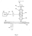
- FIG. 2 is another embodiment of the invention Lichtabtastvorraum shown.
- a light emitting device 110 e.g. a laser generates an excitation light beam 111, which refers to a schematically illustrated beam expansion optics 115 for Expansion of the excitation light beam hits.
- the beam expanding optics 115 may simultaneously contain a spatial filter to improve the beam quality.
- a dichroic beam splitter 164 the Exciting light almost completely at a right angle towards a sample 122 reflected.
- a focusing lens 165 which focuses the excitation light to a small spot on the sample.
- the sample 122 is again on a turntable 120 as in the previous embodiment removably mounted, which is rotatably supported via a rotation axis 121.
- the focusing optics are located first 165 followed by the dichroic beamsplitter 164 designed so that is the fluorescent light different in wavelength from the excitation light is almost completely transmitted to a detection optics 163, the fluorescent light focused on a pinhole 161, behind which a detector 162 is arranged.
- Embodiments may include a blocking filter for suppressing stray light from the Be provided light emission device in front of the respective detectors.
- a blocking filter for suppressing stray light from the Be provided light emission device in front of the respective detectors.
- the Barrier filter and the pinhole (which, of course, before the detectors 31 and 41 the embodiment shown in Fig. 1 is providable) is a strong suppression of achieved scattered excitation light and significantly improves the signal-to-noise ratio.
- the focusing lens 165 is combined with the beam splitter 164, the detection lens 163, the pinhole 161 and the detector 162 along the optical axis of the excitation light beam 111 between Light generating device and beam splitter displaced.
- an emission filter could also be used to match the wavelength to select the emission light.
- the light emitting device and / or the detection unit (s) could be used to arrange fixed and the light via flexible optical fibers to couple to the slidable focusing optics.
- the beam splitter could be omitted.
- Such Use of optical fibers in the embodiment shown in Fig. 1 allows a fixed arrangement of the detectors 31 and 41 with respect to the sliding movement of the Focusing lens, with a flexible connection between the detectors and the Focusing optics would be made by means of optical fibers.
- Figs. 1 and 2 would also be an arrangement conceivable for measurement in transmission.
- the beam splitter cube would respectively omitted and the detection units on the opposite side of the excitation the sample and the sample holder which is transparent in this case.
- the proof optics would then be with the linear movement of the or the excitation light beam coupled accordingly on the sample 22.
- the sample is applied to a carrier by means of a microspot application method, which is detachably mounted on the sample holder.
- the carrier can be a circular Be disc or have any other flat shape.
- the carrier is subjected to microdosing techniques, e.g. using a microdroppiezo technology, used. This makes it possible to spot single spot samples in the range of typically Apply 30 to 100 microns in diameter.
- the invention provides the significant advantage that the positioning of the scanning light beam on the sample due to the rotational movement or the linear movement is more controllable than by means of tilting the tilting mirror according to the prior Technique in which a gain of a positional tolerance as a mirror galvanometer occurred.
- the sampling time can be significant be shortened, wherein the rigid connection of the imaging and detection optics leads to an improvement of the positioning.
- the confocal arranged in front of the detectors Aperture diaphragms prevent the crosstalk of the two detectors assigned Channels and suppress stray light from the environment of the excitation light spot, causing the signal-to-noise ratio is improved.
- the possibility of multiple light emission devices and using different filters increases the flexibility of the system.
Landscapes
- Health & Medical Sciences (AREA)
- Nuclear Medicine, Radiotherapy & Molecular Imaging (AREA)
- Physics & Mathematics (AREA)
- Life Sciences & Earth Sciences (AREA)
- Chemical & Material Sciences (AREA)
- Analytical Chemistry (AREA)
- Biochemistry (AREA)
- General Health & Medical Sciences (AREA)
- General Physics & Mathematics (AREA)
- Immunology (AREA)
- Pathology (AREA)
- Investigating, Analyzing Materials By Fluorescence Or Luminescence (AREA)
- Microscoopes, Condenser (AREA)
Applications Claiming Priority (3)
| Application Number | Priority Date | Filing Date | Title |
|---|---|---|---|
| DE19707226A DE19707226A1 (de) | 1997-02-24 | 1997-02-24 | Lichtabtastvorrichtung |
| DE19707226 | 1997-02-24 | ||
| EP97953740A EP0961929B1 (fr) | 1997-02-24 | 1997-12-04 | Dispositif de balayage lumineux |
Related Parent Applications (1)
| Application Number | Title | Priority Date | Filing Date |
|---|---|---|---|
| EP97953740A Division EP0961929B1 (fr) | 1997-02-24 | 1997-12-04 | Dispositif de balayage lumineux |
Publications (2)
| Publication Number | Publication Date |
|---|---|
| EP1610117A2 true EP1610117A2 (fr) | 2005-12-28 |
| EP1610117A3 EP1610117A3 (fr) | 2006-05-10 |
Family
ID=7821242
Family Applications (2)
| Application Number | Title | Priority Date | Filing Date |
|---|---|---|---|
| EP05020027A Withdrawn EP1610117A3 (fr) | 1997-02-24 | 1997-12-04 | Dispositif à balayage de lumière |
| EP97953740A Expired - Lifetime EP0961929B1 (fr) | 1997-02-24 | 1997-12-04 | Dispositif de balayage lumineux |
Family Applications After (1)
| Application Number | Title | Priority Date | Filing Date |
|---|---|---|---|
| EP97953740A Expired - Lifetime EP0961929B1 (fr) | 1997-02-24 | 1997-12-04 | Dispositif de balayage lumineux |
Country Status (6)
| Country | Link |
|---|---|
| US (1) | US6211989B1 (fr) |
| EP (2) | EP1610117A3 (fr) |
| JP (2) | JP3660691B2 (fr) |
| AU (1) | AU5753998A (fr) |
| DE (2) | DE19707226A1 (fr) |
| WO (1) | WO1998038495A1 (fr) |
Families Citing this family (67)
| Publication number | Priority date | Publication date | Assignee | Title |
|---|---|---|---|---|
| US5631734A (en) * | 1994-02-10 | 1997-05-20 | Affymetrix, Inc. | Method and apparatus for detection of fluorescently labeled materials |
| US6048734A (en) | 1995-09-15 | 2000-04-11 | The Regents Of The University Of Michigan | Thermal microvalves in a fluid flow method |
| DE19844713C2 (de) * | 1998-09-29 | 2001-09-20 | Gsf Forschungszentrum Umwelt | Fluoreszenz-Meßvorrichtung |
| JP2000121559A (ja) * | 1998-10-14 | 2000-04-28 | Hitachi Denshi Ltd | 微小点光量読取装置 |
| JP3597729B2 (ja) * | 1999-05-11 | 2004-12-08 | 日立ソフトウエアエンジニアリング株式会社 | 蛍光測光方法及び蛍光測光装置 |
| US7423750B2 (en) * | 2001-11-29 | 2008-09-09 | Applera Corporation | Configurations, systems, and methods for optical scanning with at least one first relative angular motion and at least one second angular motion or at least one linear motion |
| US20050279949A1 (en) * | 1999-05-17 | 2005-12-22 | Applera Corporation | Temperature control for light-emitting diode stabilization |
| DE19959742A1 (de) * | 1999-12-10 | 2001-06-13 | Zeiss Carl | System zur Kompensation von Richtungs- und Positionsschwankungen eines von einem Laser erzeugten Lichtes |
| US6912076B2 (en) * | 2000-03-17 | 2005-06-28 | Accu-Sort Systems, Inc. | Coplanar camera scanning system |
| US6563581B1 (en) * | 2000-07-14 | 2003-05-13 | Applera Corporation | Scanning system and method for scanning a plurality of samples |
| US6603546B1 (en) * | 2000-07-21 | 2003-08-05 | I.S.S. (Usa) Inc. | Rapid high throughput spectrometer and method |
| CA2418271A1 (fr) | 2000-08-03 | 2002-07-04 | Perlegen Sciences | Balayage optique haute performance d'un substrat |
| US6789040B2 (en) | 2000-08-22 | 2004-09-07 | Affymetrix, Inc. | System, method, and computer software product for specifying a scanning area of a substrate |
| US6692700B2 (en) | 2001-02-14 | 2004-02-17 | Handylab, Inc. | Heat-reduction methods and systems related to microfluidic devices |
| US8895311B1 (en) | 2001-03-28 | 2014-11-25 | Handylab, Inc. | Methods and systems for control of general purpose microfluidic devices |
| US7010391B2 (en) | 2001-03-28 | 2006-03-07 | Handylab, Inc. | Methods and systems for control of microfluidic devices |
| US7323140B2 (en) | 2001-03-28 | 2008-01-29 | Handylab, Inc. | Moving microdroplets in a microfluidic device |
| US7829025B2 (en) | 2001-03-28 | 2010-11-09 | Venture Lending & Leasing Iv, Inc. | Systems and methods for thermal actuation of microfluidic devices |
| US6852287B2 (en) | 2001-09-12 | 2005-02-08 | Handylab, Inc. | Microfluidic devices having a reduced number of input and output connections |
| US6490533B2 (en) | 2001-04-26 | 2002-12-03 | Affymetrix, Inc. | System, method, and product for dynamic noise reduction in scanning of biological materials |
| US6650411B2 (en) | 2001-04-26 | 2003-11-18 | Affymetrix, Inc. | System, method, and product for pixel clocking in scanning of biological materials |
| US6643015B2 (en) | 2001-04-26 | 2003-11-04 | Affymetrix, Inc. | System, method, and product for symmetrical filtering in scanning of biological materials |
| DE10136863A1 (de) * | 2001-07-28 | 2003-02-20 | Berthold Tech Gmbh & Co Kg | Vorrichtung zur wahlweisen Messung von insbesondere Lumineszenz- und/oder Fluoreszenzstrahlung |
| EP1345026B1 (fr) | 2002-03-15 | 2010-05-05 | Affymetrix, Inc. | Système et methode de balayage de materiaux biologiques |
| DE20214868U1 (de) * | 2002-07-31 | 2003-03-13 | Tecan Trading Ag Maennedorf | Vorrichtung zum Messen der Lebensdauer der Fluoreszenz von Fluorophoren in Proben |
| US7148043B2 (en) | 2003-05-08 | 2006-12-12 | Bio-Rad Laboratories, Inc. | Systems and methods for fluorescence detection with a movable detection module |
| EP2402089A1 (fr) | 2003-07-31 | 2012-01-04 | Handylab, Inc. | Traitement d'échantillons contenant des particules |
| US7317415B2 (en) | 2003-08-08 | 2008-01-08 | Affymetrix, Inc. | System, method, and product for scanning of biological materials employing dual analog integrators |
| US8852862B2 (en) | 2004-05-03 | 2014-10-07 | Handylab, Inc. | Method for processing polynucleotide-containing samples |
| EP2345739B8 (fr) | 2004-05-03 | 2016-12-07 | Handylab, Inc. | Dispositif microfluidique permettant de traiter des échantillons contenant un polynucléotide |
| WO2006014494A2 (fr) * | 2004-07-07 | 2006-02-09 | Corcoran Timothy C | Imagerie par fluorescence a etiquettes multiples utilisant des matrices d'excitation-emission |
| WO2006027406A1 (fr) * | 2004-09-10 | 2006-03-16 | Wallac Oy | Instruments et procede de mesure optique d'un dosage de proximite homogene, luminescent, amplifie |
| JP4577645B2 (ja) * | 2004-09-30 | 2010-11-10 | 横河電機株式会社 | スクリーニング装置 |
| US7709249B2 (en) * | 2005-04-01 | 2010-05-04 | 3M Innovative Properties Company | Multiplex fluorescence detection device having fiber bundle coupling multiple optical modules to a common detector |
| US7507575B2 (en) * | 2005-04-01 | 2009-03-24 | 3M Innovative Properties Company | Multiplex fluorescence detection device having removable optical modules |
| US8351026B2 (en) | 2005-04-22 | 2013-01-08 | Affymetrix, Inc. | Methods and devices for reading microarrays |
| US7727473B2 (en) | 2005-10-19 | 2010-06-01 | Progentech Limited | Cassette for sample preparation |
| US7754148B2 (en) | 2006-12-27 | 2010-07-13 | Progentech Limited | Instrument for cassette for sample preparation |
| WO2007091530A1 (fr) * | 2006-02-07 | 2007-08-16 | The Furukawa Electric Co., Ltd. | Photodetecteur et appareil de mesure d'objet |
| US7998708B2 (en) | 2006-03-24 | 2011-08-16 | Handylab, Inc. | Microfluidic system for amplifying and detecting polynucleotides in parallel |
| US8088616B2 (en) * | 2006-03-24 | 2012-01-03 | Handylab, Inc. | Heater unit for microfluidic diagnostic system |
| EP2001990B1 (fr) | 2006-03-24 | 2016-06-29 | Handylab, Inc. | Système intégré de traitement d'échantillons microfluides et son procédé d'utilisation |
| US10900066B2 (en) | 2006-03-24 | 2021-01-26 | Handylab, Inc. | Microfluidic system for amplifying and detecting polynucleotides in parallel |
| US11806718B2 (en) | 2006-03-24 | 2023-11-07 | Handylab, Inc. | Fluorescence detector for microfluidic diagnostic system |
| US8009889B2 (en) | 2006-06-27 | 2011-08-30 | Affymetrix, Inc. | Feature intensity reconstruction of biological probe array |
| EP2091647A2 (fr) | 2006-11-14 | 2009-08-26 | Handylab, Inc. | Système microfluidique utilisé pour amplifier et détecter des polynucléotides en parallèle |
| WO2008060604A2 (fr) | 2006-11-14 | 2008-05-22 | Handylab, Inc. | Système microfluidique utilisé pour amplifier et détecter des polynucléotides en parallèle |
| AU2008276211B2 (en) | 2007-07-13 | 2015-01-22 | Handylab, Inc. | Polynucleotide capture materials, and methods of using same |
| US8133671B2 (en) | 2007-07-13 | 2012-03-13 | Handylab, Inc. | Integrated apparatus for performing nucleic acid extraction and diagnostic testing on multiple biological samples |
| USD621060S1 (en) | 2008-07-14 | 2010-08-03 | Handylab, Inc. | Microfluidic cartridge |
| US9618139B2 (en) * | 2007-07-13 | 2017-04-11 | Handylab, Inc. | Integrated heater and magnetic separator |
| AU2013205267B2 (en) * | 2007-07-13 | 2015-08-13 | Handylab, Inc. | Integrated apparatus for performing nucleic acid extraction and diagnostic testing on multiple biological samples |
| US8182763B2 (en) | 2007-07-13 | 2012-05-22 | Handylab, Inc. | Rack for sample tubes and reagent holders |
| US20090136385A1 (en) | 2007-07-13 | 2009-05-28 | Handylab, Inc. | Reagent Tube |
| US9186677B2 (en) | 2007-07-13 | 2015-11-17 | Handylab, Inc. | Integrated apparatus for performing nucleic acid extraction and diagnostic testing on multiple biological samples |
| US8105783B2 (en) | 2007-07-13 | 2012-01-31 | Handylab, Inc. | Microfluidic cartridge |
| US8287820B2 (en) | 2007-07-13 | 2012-10-16 | Handylab, Inc. | Automated pipetting apparatus having a combined liquid pump and pipette head system |
| USD618820S1 (en) | 2008-07-11 | 2010-06-29 | Handylab, Inc. | Reagent holder |
| USD787087S1 (en) | 2008-07-14 | 2017-05-16 | Handylab, Inc. | Housing |
| US9767342B2 (en) | 2009-05-22 | 2017-09-19 | Affymetrix, Inc. | Methods and devices for reading microarrays |
| BR112012021202B1 (pt) | 2010-02-23 | 2020-06-09 | Genturadx Usa Inc | aparelho e métodos para preparação, reação e detecção integradas de amostras |
| ES2769028T3 (es) | 2011-04-15 | 2020-06-24 | Becton Dickinson Co | Termociclador microfluídico de barrido en tiempo real |
| CA2834790C (fr) | 2011-05-04 | 2019-04-09 | Luminex Corporation | Appareil et procede pour la preparation, la reaction et la detection integrees d'echantillons |
| EP3273253B1 (fr) | 2011-09-30 | 2020-08-26 | Becton, Dickinson and Company | Bande de réactif unifiée |
| USD692162S1 (en) | 2011-09-30 | 2013-10-22 | Becton, Dickinson And Company | Single piece reagent holder |
| WO2013067202A1 (fr) | 2011-11-04 | 2013-05-10 | Handylab, Inc. | Dispositif de préparation d'échantillons de polynucléotides |
| BR112014018995B1 (pt) | 2012-02-03 | 2021-01-19 | Becton, Dickson And Company | sistemas para executar ensaio automatizado |
Citations (7)
| Publication number | Priority date | Publication date | Assignee | Title |
|---|---|---|---|---|
| US5091652A (en) * | 1990-01-12 | 1992-02-25 | The Regents Of The University Of California | Laser excited confocal microscope fluorescence scanner and method |
| EP0504432A1 (fr) * | 1990-10-09 | 1992-09-23 | Idemitsu Petrochemical Co. Ltd. | Procede d'analyse immunologique quantitative |
| US5223718A (en) * | 1992-08-10 | 1993-06-29 | Alcor, Inc. | Method and apparatus for quantifying thermal oxidation tester tube deposits |
| US5459325A (en) * | 1994-07-19 | 1995-10-17 | Molecular Dynamics, Inc. | High-speed fluorescence scanner |
| WO1996009548A1 (fr) * | 1994-09-21 | 1996-03-28 | The University Court Of The University Of Glasgow | Dispositif et procede destines a effectuer des analyses d'echantillons |
| US5537247A (en) * | 1994-03-15 | 1996-07-16 | Technical Instrument Company | Single aperture confocal imaging system |
| EP0753779A2 (fr) * | 1995-07-13 | 1997-01-15 | Yokogawa Electric Corporation | Microscope confocal |
Family Cites Families (4)
| Publication number | Priority date | Publication date | Assignee | Title |
|---|---|---|---|---|
| US3918812A (en) * | 1973-05-07 | 1975-11-11 | Us Energy | Diagnoses of disease states by fluorescent measurements utilizing scanning laser beams |
| US4405993A (en) * | 1981-01-02 | 1983-09-20 | Hewlett-Packard Company | Liquid crystal disc memory system |
| US4626684A (en) * | 1983-07-13 | 1986-12-02 | Landa Isaac J | Rapid and automatic fluorescence immunoassay analyzer for multiple micro-samples |
| US5022757A (en) * | 1989-01-23 | 1991-06-11 | Modell Mark D | Heterodyne system and method for sensing a target substance |
-
1997
- 1997-02-24 DE DE19707226A patent/DE19707226A1/de not_active Withdrawn
- 1997-12-04 US US09/367,949 patent/US6211989B1/en not_active Expired - Lifetime
- 1997-12-04 JP JP53720398A patent/JP3660691B2/ja not_active Expired - Fee Related
- 1997-12-04 WO PCT/EP1997/006793 patent/WO1998038495A1/fr active IP Right Grant
- 1997-12-04 DE DE59712623T patent/DE59712623D1/de not_active Expired - Lifetime
- 1997-12-04 EP EP05020027A patent/EP1610117A3/fr not_active Withdrawn
- 1997-12-04 AU AU57539/98A patent/AU5753998A/en not_active Abandoned
- 1997-12-04 EP EP97953740A patent/EP0961929B1/fr not_active Expired - Lifetime
-
2005
- 2005-01-24 JP JP2005015926A patent/JP2005140796A/ja active Pending
Patent Citations (7)
| Publication number | Priority date | Publication date | Assignee | Title |
|---|---|---|---|---|
| US5091652A (en) * | 1990-01-12 | 1992-02-25 | The Regents Of The University Of California | Laser excited confocal microscope fluorescence scanner and method |
| EP0504432A1 (fr) * | 1990-10-09 | 1992-09-23 | Idemitsu Petrochemical Co. Ltd. | Procede d'analyse immunologique quantitative |
| US5223718A (en) * | 1992-08-10 | 1993-06-29 | Alcor, Inc. | Method and apparatus for quantifying thermal oxidation tester tube deposits |
| US5537247A (en) * | 1994-03-15 | 1996-07-16 | Technical Instrument Company | Single aperture confocal imaging system |
| US5459325A (en) * | 1994-07-19 | 1995-10-17 | Molecular Dynamics, Inc. | High-speed fluorescence scanner |
| WO1996009548A1 (fr) * | 1994-09-21 | 1996-03-28 | The University Court Of The University Of Glasgow | Dispositif et procede destines a effectuer des analyses d'echantillons |
| EP0753779A2 (fr) * | 1995-07-13 | 1997-01-15 | Yokogawa Electric Corporation | Microscope confocal |
Also Published As
| Publication number | Publication date |
|---|---|
| JP2000509826A (ja) | 2000-08-02 |
| EP0961929A1 (fr) | 1999-12-08 |
| DE59712623D1 (de) | 2006-05-24 |
| US6211989B1 (en) | 2001-04-03 |
| DE19707226A1 (de) | 1998-08-27 |
| JP2005140796A (ja) | 2005-06-02 |
| AU5753998A (en) | 1998-09-18 |
| EP1610117A3 (fr) | 2006-05-10 |
| EP0961929B1 (fr) | 2006-04-19 |
| JP3660691B2 (ja) | 2005-06-15 |
| WO1998038495A1 (fr) | 1998-09-03 |
Similar Documents
| Publication | Publication Date | Title |
|---|---|---|
| EP0961929B1 (fr) | Dispositif de balayage lumineux | |
| DE10004191B4 (de) | Fluoreszenz-Scanmikroskop | |
| DE60202027T2 (de) | Multi-Photonen-Endoskop | |
| DE19653413C2 (de) | Rastermikroskop, bei dem eine Probe in mehreren Probenpunkten gleichzeitig optisch angeregt wird | |
| EP0961945B1 (fr) | Dispositif de balayage lumineux | |
| EP1354234B1 (fr) | Systeme optique et procede d'activation et de mesure de la fluorescence sur ou dans des echantillons traites avec des colorants fluorescents | |
| DE10105391A1 (de) | Scanmikroskop und Modul für ein Scanmikroskop | |
| DE10038528A1 (de) | Verfahren und Anordnung zur Erhöhung der spektralen und räumlichen Detektorauflösung | |
| DE102007047461A1 (de) | Verfahren und optische Anordnung zur Untersuchung einer Probe | |
| DE10043992B4 (de) | Verfahren zur Untersuchung einer Probe und konfokales Scan-Mikroskop | |
| EP1420281A2 (fr) | Méthode et dispositif pour l'acquisition optique à vaste profondeur de champ | |
| EP0941470B1 (fr) | Module de spectroscopie a correlation de fluorescence pour un microscope | |
| EP1496386A2 (fr) | Système pour la détection de la radiation émise ou rétrodiffusée par un échantillon comprenant deux objectifs | |
| DE10121064A1 (de) | Vorrichtung und Verfahren zur optischen Messung von chemischen und/oder biologischen Proben | |
| DE19822869C2 (de) | Optisches Nahfeldmikroskop | |
| DE10231776B4 (de) | Verfahren zur Scanmikroskopie und Scanmikroskop | |
| WO2004055570A2 (fr) | Microscope coherent | |
| EP0961930A1 (fr) | Dispositif de balayage lumineux | |
| DE19950225A1 (de) | Anordnung zur optischen Abtastung eines Objekts | |
| EP1049952B1 (fr) | Systeme de balayage optique d'un objet | |
| DE10209322A1 (de) | Vorrichtung zum Ablenken eines Lichtstrahles und Scanmikroskop | |
| DE102012211780A1 (de) | Vorrichtung zur Halterung und Beleuchtung von Proben für ein Mikroskop | |
| WO2002090947A2 (fr) | Microscope pour analyse de la fluctuation de fluorescence et module de mesure ou module de balayage de la fluctuation de fluorescence et procede de mesure de la fluctuation de fluorescence ainsi que procede et dispositif d'alignement d'un microscope pour analyse de la fluctuation de fluorescence | |
| DE20221635U1 (de) | Optisches System zum Anregen und Messen von Fluoreszenz an oder in mit Fluoreszenzfarbstoffen behandelten Proben | |
| LU92846B1 (de) | Verfahren und Beleuchtungsanordnung zum Beleuchten einer Probenschicht mit einem Lichtblatt |
Legal Events
| Date | Code | Title | Description |
|---|---|---|---|
| PUAI | Public reference made under article 153(3) epc to a published international application that has entered the european phase |
Free format text: ORIGINAL CODE: 0009012 |
|
| AC | Divisional application: reference to earlier application |
Ref document number: 0961929 Country of ref document: EP Kind code of ref document: P |
|
| AK | Designated contracting states |
Kind code of ref document: A2 Designated state(s): AT BE CH DE DK ES FI FR GB GR IE IT LI LU MC NL PT SE |
|
| AX | Request for extension of the european patent |
Extension state: AL LT LV MK RO SI |
|
| PUAL | Search report despatched |
Free format text: ORIGINAL CODE: 0009013 |
|
| AK | Designated contracting states |
Kind code of ref document: A3 Designated state(s): AT BE CH DE DK ES FI FR GB GR IE IT LI LU MC NL PT SE |
|
| AX | Request for extension of the european patent |
Extension state: AL LT LV MK RO SI |
|
| 17P | Request for examination filed |
Effective date: 20061030 |
|
| 17Q | First examination report despatched |
Effective date: 20061208 |
|
| AKX | Designation fees paid |
Designated state(s): DE FR GB IT NL |
|
| GRAP | Despatch of communication of intention to grant a patent |
Free format text: ORIGINAL CODE: EPIDOSNIGR1 |
|
| RAP1 | Party data changed (applicant data changed or rights of an application transferred) |
Owner name: BODENSEEWERK PERKIN-ELMER GMBH |
|
| INTG | Intention to grant announced |
Effective date: 20160617 |
|
| INTG | Intention to grant announced |
Effective date: 20160620 |
|
| STAA | Information on the status of an ep patent application or granted ep patent |
Free format text: STATUS: THE APPLICATION IS DEEMED TO BE WITHDRAWN |
|
| 18D | Application deemed to be withdrawn |
Effective date: 20161101 |