EP1607809B1 - Vefahren zur Generierung von optimalen Steuerungsproblemen für industrielle Prozesse - Google Patents
Vefahren zur Generierung von optimalen Steuerungsproblemen für industrielle Prozesse Download PDFInfo
- Publication number
- EP1607809B1 EP1607809B1 EP04405350A EP04405350A EP1607809B1 EP 1607809 B1 EP1607809 B1 EP 1607809B1 EP 04405350 A EP04405350 A EP 04405350A EP 04405350 A EP04405350 A EP 04405350A EP 1607809 B1 EP1607809 B1 EP 1607809B1
- Authority
- EP
- European Patent Office
- Prior art keywords
- mld
- subsystems
- dependent
- subsystem
- variables
- Prior art date
- Legal status (The legal status is an assumption and is not a legal conclusion. Google has not performed a legal analysis and makes no representation as to the accuracy of the status listed.)
- Expired - Lifetime
Links
Images
Classifications
-
- G—PHYSICS
- G05—CONTROLLING; REGULATING
- G05B—CONTROL OR REGULATING SYSTEMS IN GENERAL; FUNCTIONAL ELEMENTS OF SUCH SYSTEMS; MONITORING OR TESTING ARRANGEMENTS FOR SUCH SYSTEMS OR ELEMENTS
- G05B13/00—Adaptive control systems, i.e. systems automatically adjusting themselves to have a performance which is optimum according to some preassigned criterion
- G05B13/02—Adaptive control systems, i.e. systems automatically adjusting themselves to have a performance which is optimum according to some preassigned criterion electric
- G05B13/04—Adaptive control systems, i.e. systems automatically adjusting themselves to have a performance which is optimum according to some preassigned criterion electric involving the use of models or simulators
- G05B13/042—Adaptive control systems, i.e. systems automatically adjusting themselves to have a performance which is optimum according to some preassigned criterion electric involving the use of models or simulators in which a parameter or coefficient is automatically adjusted to optimise the performance
Definitions
- the invention relates to the field of industrial process modelling, optimal control and advanced scheduling. It departs from a method of merging two arbitrarily interconnected Mixed Logical Dynamic (MLD) subsystems into a combined MLD system and a method of designing a model based controller or scheduler for real-time control or scheduling of an industrial process.
- MLD Mixed Logical Dynamic
- MLD Mixed logical dynamical
- the variables mentioned are vectors and A , B i , C , D i , E i are matrices of suitable dimensions.
- the MLD system (Eqs.1) must be such that for any given x(t) and u(t) the values of ⁇ ( t ) and z ( t ) are defined uniquely.
- Formulations or relationships in the form of Eqs.1 appear naturally when logical statements are written as propositional calculus expressions, or when bounds on the states are set explicitly.
- MLD systems generalize a wide set of models, among which there are linear hybrid systems and even nonlinear systems whose nonlinearities can be expressed or at least suitably approximated by piecewise linear functions.
- Model predictive control is a procedure of solving an optimal-control problem, which includes system dynamics and constraints on the system output, state and input variables.
- the main idea of model predictive control is to use a model of the plant or process, valid at least around a certain operating point, to predict the future evolution of the system. Based on this prediction, at each time step t the controller selects a sequence of future command inputs or control signals through an on-line optimization procedure, which aims at optimizing a performance, cost or objective function, and enforces fulfillment of the constraints. Only the first sample of the optimal sequence of future command inputs is actually applied to the system at time t . At time t +1, a new sequence is evaluated to replace the previous one. This on-line re-planning provides the desired feedback control feature.
- Model Predictive Control can be applied for stabilizing a MLD system to an equilibrium state or to track a desired reference trajectory via feedback control.
- MILP Mixed Integer Linear Programming
- the vector g denotes a cost vector
- the matrix A is a constraint matrix
- the vector b is termed a boundary vector.
- Standard procedures can be adapted to handle time varying parameters such as cost and price coefficients.
- the solution of the MILP problem can be obtained by reverting to the commercial optimisation problem solver for solving linear, mixed-integer and quadratic programming problems called CPLEX (http://www.ilog.com/products/cplex/) .
- Model predictive control in combination with Mixed Logical Dynamical (MLD) systems descriptions has been used for modeling and control of processes in the utility automation and process industry.
- MPC Model predictive control
- MLD Mixed Logical Dynamical
- the original MLD subsystems are related or connected via pairs of dependent input and output variables, which pairs are transformed into additional auxiliary variables of the combined MLD system.
- the equations describing the original MLD subsystems and involving said dependent input and output variables in turn are converted into constraints of the combined MLD system involving the additional auxiliary variables.
- the core technical aspect of the invention concerns the automatic merging of two arbitrarily connected MLD subsystems into one composite MLD system.
- a repeated use of the merging procedure allows to generate any arbitrarily complex MLD system containing the complete description of an industrial process.
- the industrial process can be decomposed in several sub-processes, each MLD subsystem representing a sub-process is established independently from the others in the MLD framework, and the industrial process is reproduced as a sequence of interconnected MLD blocks.
- an optimal control problem is generated via adding an ultimate MLD block whose unique output becomes the objective function of the problem.
- MPC Model Predictive Control
- the invention simplifies the modelling of complex industrial processes in the Mixed Logical Dynamic (MLD) framework and allows to automatically generate and solve optimal control problems and scheduling applications for said industrial processes. Preferably, this is done by graphically representing any MLD subsystem by a block whose input / output ports match the input / output variables of the MLD formulation. In a graphical environment, any specific industrial process may then be reproduced by instantiating blocks from a library of basic MLD elements or atomic MLD blocks and by properly connecting them in order to obtain a graphical representation of the process. In case an appropriate library is available, this procedure will not require any expert knowledge from the end user apart from the ability to build the graphical interconnections mentioned.
- MLD Mixed Logical Dynamic
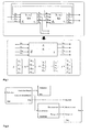
- Fig.1 shows two MLD blocks or subsystems S1 and S2 , defined respectively by the matrices A 1 , B 1 1..3 , C 1 , D 1 1...3 , E 1 1...5 and A 2 , B 2 1..3 , C 2 , D 2 1....3 , E 2 1...5 , as well as by the vectors of states s 1 , x 2 , the vectors of inputs u 1 , u 2 , the vectors of outputs y 1 , y 2 , the vectors of real auxiliary variables z 1 , z 2 , and the vectors of Boolean auxiliary variables ⁇ 1 , ⁇ 2 .
- the MLD subsystem S1, S2 are interconnected as indicated by the arrows joining the two blocks.
- the goal is to merge S1 and S2 in order to obtain one single or combined MLD system S described by the matrices A , B 1..3 , C , D 1 ,..,3, E 1,..,5 and the corresponding vectors of states x , inputs u , outputs y , real auxiliary variables z and Boolean auxiliary variables ⁇ .
- the vectors of states, inputs and outputs can contain both real (denoted with the index r ) and Boolean (index b ) variables. If this is the case, all the real variables will have to be grouped and placed in the corresponding vector before the Boolean ones.
- certain variables are independent of the other MLD block (denoted with the prefix i ) and some are dependent (prefix d ). Pairs of the dependent variables are represented in Fig.1 by a common arrow pointing from one MLD block ( S1, S2) to the other MLD block ( S2 , S1).
- the other matrices B 1..3 involved in the state dynamic of the system S based on the corresponding matrices (B1 1..3 , B 2 1..3 ) of the subsystems S1, S2, undergo, in a first step, a corresponding swap of rows.
- a swap of columns is executed on the matrices C , E 4 of the system S multiplying the resulting state vector x and being based on the corresponding matrices ( C 1 , E 1 4 ; C 2 , E 2 4 ) of the subsystems S1, S2.
- the matrices involved in the output dynamic (C, D 1...3 ) of the system S are based on the corresponding matrices ( C 1 , D 1 1...3 ; C 2 , D 2 1,...3 ) of the subsystems S1, S2.
- u [i u r1 , i u r2 , i u b1 , i u b2 ] .
- the input matrix B 1 in a second step, will undergo a swap between the columns corresponding to i u b 1 and i u , 2 and, in a third step, will have to have the columns corresponding to the dependent inputs ( d u r1 ,d u b1 and d u r2 , d u b2 ) deleted.
- the other input matrices D 1 , E 1 of the system S being based on the matrices (D 1 1 , E 1 1 ; D 2 1 , E 2 1 ) of the subsystems S1, S2 , will undergo a swap of columns between i u b1 and i u r 2 and, in a second step, will have the columns corresponding to the dependent inputs (d u r1 , d u b1 ; d u r2 , d u b2 ) deleted.
- the eliminated real dependent inputs d u r1 , d u r2 will then be substituted by additional real auxiliary variables z 12 , z 21 added to the real auxiliary variables z of the combined system S .
- Boolean dependent inputs d u b1 , d u b2 will be replaced by additional Boolean auxiliary variables ⁇ 12 , ⁇ 21 , added to the Boolean auxiliary variables ⁇ of the combined system S.
- This transformation is obtained or executed by appending the columns deleted from the matrices B 1 , D 1 and E 1 (observing a change of sign for the latter) to the matrices B 3 , D 3 , and E 3 if real or to the matrices B 2 , D 2 , and E 2 if Boolean.
- Eq.1b comprises terms of the type D 1 1 d u 1 wherein the dependent inputs d u 1 have to be replaced by the additional auxiliary real and/or Boolean variables ( z 12, ⁇ 12 ) introduced above. Likewise, the dependent inputs d u 2 have to be replaced by the additional auxiliary variables ( z 2I , ⁇ 21 ) introduced above.
- the combined or merged MLD system S resulting from the procedure outlined above in turn can be considered as a subsystem itself.
- a complex MLD system S tot representing all relevant technical aspects of an arbitrarily complex industrial installation or process can be generated. Thereby order of merging of the "basic" MLD subsystems or "atomic" MLD blocks does not have any impact on the final result and may be chosen at will.
- an objective function or cost functional f has to be defined.
- this is most conveniently done via adding a functional MLD subsystem S cost comprising exactly one independent scalar output variable y cost representing the objective to be optimized.
- This functional MLD subsystem S cost is ultimately merged to the complex MLD system S tot representing all relevant technical aspects of the physical process.
- all the outputs of the complex MLD system S tot that are related to costs are regarded as dependent outputs with corresponding dependent inputs of the functional MLD subsystem S cost .
- the method according to the invention is completely general and can be applied to many industrial processes with a limited effort.
- a particular implementation of the invention in a cement plant is presented in more detail with reference to Fig.2 .
- Cement mill scheduling implies deciding when to produce a certain cement grade on which mills. Due to the number of mills, grades, silos, conveyor belts and the various operating constraints the problem is quite complex. In a hybrid system framework, the mills are treated as finite state or on/off machines that associate different energy consumptions and throughputs depending on the cement grade produced. Generally, a library of basic MLD blocks or subsystems is provided for each basic element or sub-process of the complex industrial process being modeled. In a cement mills scheduling example, these blocks typically consist of the MLD formulation for a "mill”, “silo" and "electricity".
- the representation of the grinding section of a cement plant according to Fig.2 comprises one MLD block associated to the Cement Mill (one input, three outputs), one MLD block associated to the Cement Silo (one input) and one associated to the Electricity section (one input, two outputs).
- the optimal control problem is generated via adding a functional or cost MLD block, of which the unique output variable y cost becomes the objective function of the problem.
- the next step is to iteratively merge two interconnected MLD blocks to obtain a combined block, until only one block is left.
- the final MLD block, resulting from the merging process will have as inputs all the independent inputs of the various MLD subsystems, i.e.
- Fig.2 represent interconnections between the individual blocks or subsystems just as in Fig.1 .
Landscapes
- Engineering & Computer Science (AREA)
- Software Systems (AREA)
- Artificial Intelligence (AREA)
- Computer Vision & Pattern Recognition (AREA)
- Evolutionary Computation (AREA)
- Medical Informatics (AREA)
- Health & Medical Sciences (AREA)
- Physics & Mathematics (AREA)
- General Physics & Mathematics (AREA)
- Automation & Control Theory (AREA)
- Feedback Control In General (AREA)
- General Factory Administration (AREA)
- Management, Administration, Business Operations System, And Electronic Commerce (AREA)
Claims (7)
- Verfahren zum Entwurf einer auf Modellen basierenden Steuerung oder Ablaufsteuerung zur Echtzeitsteuerung oder Ablaufsteuerung eines industriellen Prozesses, wobei die Steuerung oder Ablaufsteuerung auf einem gemischt logisch-dynamischen bzw. MLD-System (S) basiert, das den industriellen Prozeß repräsentiert und durch Zusammenführen zweier beliebig verbundener gemischt logisch-dynamischer bzw. MLD-Teilsysteme (S1, S2) erhalten wird, wobei- jedes MLD-Teilsystem (S1, S2) einen Teilprozeß des industriellen Prozesses repräsentiert,- in den MLD-Teilsystemen (S1, S2) und dem kombinierten MLD-System (S) jeweils Vektoren von Zuständen ( x 1, x 2, x ), Vektoren von Eingaben ( u 1 , u 2 , u), Vektoren von Ausgaben ( y 1 , y 2, y ), reelle Hilfsvariablen ( z 1 , z 2 , z ) und boolesche Hilfsvariablen (δ 1, δ 2 , δ) vorkommen und sie durch eine Zustandsgleichung (Gl. 1a), eine Ausgangsgleichung (Gl. 1b) und Nebenbedingungen (Gl. 1c) beschrieben werden,- die beiden Teilsysteme (S1, S2) über abhängige Paare (dy 1 , du 2, dy 2, du 1 ) verbunden werden, die durch eine abhängige Ausgabe (dy 1, dy 2) eines Teilsystems (S1, S2) und eine abhängige Eingabe (du 2, du 1) des anderen Teilsystems (S2, S1) gebildet werden und- die unabhängigen Eingaben (iu 1, iu 2) und Ausgaben (iy 1, iy 2) der Teilsysteme (S1, S2) nicht Teil der abhängigen Paare (dy 1, du 2, dy 2, du 1) sind,dadurch gekennzeichnet, daß- der Zustandsvektor ( x ) des kombinierten Systems (S) aus den entsprechenden Zuständen ( x 1; x 2 ) der Teilsysteme (S1, S2) zusammengesetzt ist,- die Eingangs- und Ausgangsvektoren ( u, y ) des kombinierten Systems (S) aus den entsprechenden unabhängigen Eingaben S(iu 1, iu 2 ) und Ausgaben (iv 1, i v2 ) der Teilsysteme (S1, S2) zusammengesetzt sind,- die Hilfsvariablen ( z , δ) des kombinierten Systems (S) die entsprechenden Hilfsvariablen (z 1, δ 1; z 2, δ 1 ) der Teilsysteme (S1, S2) umfassen,- jedes abhängige Paar (dy 1, du 2; dy 2, du 1) durch eine zusätzliche reelle und/oder boolesche Hilfsvariable (z 12, z 21, δ 12, δ 21) des kombinierten Systems (S) ersetzt wird,- die Ausgangsgleichungen (G1. 1b) für die abhängigen Ausgaben (dy 1, dy 2 ) jedes Teilsystems (S1, S2) in zusätzliche Nebenbedingungen (G1. 1d) des kombinierten Systems (S) umgesetzt werden, in dem die zusätzlichen reellen und/oder booleschen Hilfsvariablen (z 12, z 21, δ 12, δ 21) vorkommen.
- Verfahren nach Anspruch 1, wobei in den Gleichungen (G1. 1) für die Teilsysteme (S1, S2) Matrizen (A1 , B1, C1, D1, E1; A2, B2, C2, D2, E2) vorkommen, die zu entsprechenden Matrizen (A, B, C, D, E) für das kombinierte System (S) kombiniert werden,
dadurch gekennzeichnet, daß die Zeilen und Spalten der Matrizen (A, B, C, D, E) für das kombinierte System (S), die abhängigen Eingaben (du 1, du 2) und Ausgaben (dy1, dy2) entsprechen, eliminiert und durch zusätzliche Zeilen und Spalten ersetzt werden, die den reellen und/oder booleschen Hilfsvariablen (z 12, z 21, δ 12, δ 21) entsprechen. - Verfahren nach Anspruch 1 oder Anspruch 2, dadurch gekennzeichnet, daß das kombinierte MLD-System (S) als ein MLD-Teilsystem betrachtet und seinerseits mit einem weiteren Teilsystem (S3) zusammengeführt wird.
- Verfahren nach Anspruch 3, dadurch gekennzeichnet, daß durch iteratives Kombinieren von MLD-Teilsystemen (S1, S2, S, S3) ein komplexes MLD-System (Stot ) erzeugt wird.
- Verfahren nach Anspruch 4, dadurch gekennzeichnet, daß eines der MLD-Teilsysteme ein funktionales MLD-Teilsystem (Scost ) ist, das eine eindeutige skalare unabhängige Ausgangsvariable (ycost) umfaßt, die ein zu optimierendes Ziel des komplexen MLD-Systems (Stot) repräsentiert.
- Auf Modellen basierende Steuerung oder Ablaufsteuerung zur Echtzeitsteuerung oder Ablaufsteuerung eines industriellen Prozesses, wobei die Steuerung oder Ablaufsteuerung auf einem gemischt logisch-dynamischen bzw. MLD-System (S) basiert, das den industriellen Prozeß repräsentiert und durch Zusammenführen zweier beliebig verbundener gemischt logisch-dynamischer bzw. MLD-Teilsysteme (S1, S2) erhalten wird, wobei- jedes MLD-Teilsystem (S1, S2) einen Teilprozeß des industriellen Prozesses repräsentiert,- in den MLD-Teilsystemen (S1, S2) und dem kombinierten MLD-System (S) jeweils Vektoren von Zuständen ( x 1, x 2, x ), Vektoren von Eingaben ( u 1, u 2, u) , Vektoren von Ausgaben ( y 1, y 2 , y ) , reelle Hilfsvariablen ( z 1 , z 2 , z ) und boolesche Hilfsvariablen ( δ 1, δ 2 , δ) vorkommen und sie durch eine Zustandsgleichung (Gl. 1a), eine Ausgangsgleichung (Gl. 1b) und Nebenbedingungen (Gl. 1c) beschrieben werden,- die beiden Teilsysteme (S1, S2) über abhängige Paare (dy 1 , du 2, dy 2, du 1) verbunden werden, die durch eine abhängige Ausgabe (dy 1, dy 2) eines Teilsystems (S1, S2) und eine abhängige Eingabe (du 2, du 1) des anderen Teilsystems (S2, S1) gebildet werden und- die unabhängigen Eingaben (iu 1, iu 2 ) und Ausgaben (iy 1, iy 2 ) der Teilsysteme (S1, S2) nicht Teil der abhängigen Paare (dy 1, du 2, dy 2 , du 1) sind,dadurch gekennzeichnet, daß- der Zustandsvektor (x ) des kombinierten Systems (S) aus den entsprechenden Zuständen (x 1 ; x 2 ) der Teilsysteme (S1, S2) zusammengesetzt ist,- die Eingangs- und Ausgangsvektoren ( u, y ) des kombinierten Systems (S) aus den entsprechenden unabhängigen Eingaben (iu 1, iu 2 ) und Ausgaben (iy 1 , iy 2) der Teilsysteme (S1, S2) zusammengesetzt sind,- die Hilfsvariablen ( z, δ ) des kombinierten Systems (S) die entsprechenden Hilfsvariablen ( z 1, δ 1; z 2, δ 2 ) der Teilsysteme (S1, S2) umfassen,- jedes abhängige Paar (dy 1, du 2; dy 2, du 1 ) durch eine zusätzliche reelle und/oder boolesche Hilfsvariable ( z 12, z 21, δ 12, δ 21 ) des kombinierten Systems (S) ersetzt wird,- die Ausgangsgleichungen (Gl. 1b) für die abhängigen Ausgaben (dy1, dy2) jedes Teilsystems (S1, S2) in zusätzliche Nebenbedingungen (G1. 1d) des kombinierten Systems (S) umgesetzt werden, in denen die zusätzlichen reellen und/oder booleschen Hilfsvariablen (z 12, z 21, δ 12, δ 21) vorkommen.
- Steuerung oder Ablaufsteuerung nach Anspruch 6, dadurch gekennzeichnet, daß eines der MLD-Teilsysteme ein funktionales MLD-Teilsystem (Scost ) ist, das eine eindeutige skalare unabhängige Ausgangsvariable (ycost) umfaßt, die ein Ziel des MLD-System (S) repräsentiert, und daß die Ausgangsvariable (ycost) in einer Formulierung der modellprädiktiven Steuerung (MPC) mit den unabhängigen Eingaben (iu ) der MLD-Teilsysteme als Befehls- oder Steuervariablen verwendet wird.
Priority Applications (8)
| Application Number | Priority Date | Filing Date | Title |
|---|---|---|---|
| EP04405350A EP1607809B1 (de) | 2004-06-07 | 2004-06-07 | Vefahren zur Generierung von optimalen Steuerungsproblemen für industrielle Prozesse |
| ES04405350T ES2301956T3 (es) | 2004-06-07 | 2004-06-07 | Metodo de generacion de problemas de control optimo para procesos industriales. |
| DE602004012399T DE602004012399T2 (de) | 2004-06-07 | 2004-06-07 | Vefahren zur Generierung von optimalen Steuerungsproblemen für industrielle Prozesse |
| AT04405350T ATE389200T1 (de) | 2004-06-07 | 2004-06-07 | Vefahren zur generierung von optimalen steuerungsproblemen für industrielle prozesse |
| JP2007513655A JP4594385B2 (ja) | 2004-06-07 | 2005-06-06 | 産業プロセスのための最適制御問題を生成する方法 |
| PCT/CH2005/000317 WO2005121910A1 (en) | 2004-06-07 | 2005-06-06 | Method of generating optimal control problems for industrial processes |
| CNA2005800183270A CN1965271A (zh) | 2004-06-07 | 2005-06-06 | 产生针对工业过程的最优控制问题的方法 |
| US11/633,031 US7933664B2 (en) | 2004-06-07 | 2006-12-04 | Method of generating optimal control problems for industrial processes |
Applications Claiming Priority (1)
| Application Number | Priority Date | Filing Date | Title |
|---|---|---|---|
| EP04405350A EP1607809B1 (de) | 2004-06-07 | 2004-06-07 | Vefahren zur Generierung von optimalen Steuerungsproblemen für industrielle Prozesse |
Publications (2)
| Publication Number | Publication Date |
|---|---|
| EP1607809A1 EP1607809A1 (de) | 2005-12-21 |
| EP1607809B1 true EP1607809B1 (de) | 2008-03-12 |
Family
ID=34932136
Family Applications (1)
| Application Number | Title | Priority Date | Filing Date |
|---|---|---|---|
| EP04405350A Expired - Lifetime EP1607809B1 (de) | 2004-06-07 | 2004-06-07 | Vefahren zur Generierung von optimalen Steuerungsproblemen für industrielle Prozesse |
Country Status (8)
| Country | Link |
|---|---|
| US (1) | US7933664B2 (de) |
| EP (1) | EP1607809B1 (de) |
| JP (1) | JP4594385B2 (de) |
| CN (1) | CN1965271A (de) |
| AT (1) | ATE389200T1 (de) |
| DE (1) | DE602004012399T2 (de) |
| ES (1) | ES2301956T3 (de) |
| WO (1) | WO2005121910A1 (de) |
Families Citing this family (13)
| Publication number | Priority date | Publication date | Assignee | Title |
|---|---|---|---|---|
| JP4962839B2 (ja) * | 2006-05-30 | 2012-06-27 | トヨタ自動車株式会社 | 燃料電池システム及びその制御方法 |
| CN101403893B (zh) * | 2008-11-17 | 2010-06-02 | 杭州电子科技大学 | 染色配方的自动生成方法 |
| EP2273327A1 (de) | 2009-06-24 | 2011-01-12 | ABB Research Ltd. | Schätzen der Anfangszustände eines Systemmodells für die Steuerung eines industriellen Prozesses. |
| US8897900B2 (en) * | 2011-03-18 | 2014-11-25 | Rockwell Automation Technologies, Inc. | Graphical language for optimization and use |
| DE102011081547A1 (de) | 2011-08-25 | 2013-02-28 | Siemens Aktiengesellschaft | Einstellung einer industriellen Anlage |
| CN102508436B (zh) * | 2011-11-21 | 2014-07-16 | 湖南大学 | 机械手摩擦力动力学精确分析与控制应用方法 |
| DE102012018522B4 (de) * | 2012-09-18 | 2015-05-13 | INPRO Innovationsgesellschaft für fortgeschrittene Produktionssysteme in der Fahrzeugindustrie mbH | Verfahren und Anlage zur parallelen Verfolgung von ortszugeordneten energieverbrauchbeeinflussenden Ereignissen einer industriellen Produktionsanlage |
| IN2015DN03201A (de) | 2012-11-07 | 2015-10-02 | Beckman Coulter Inc | |
| WO2014090310A1 (en) * | 2012-12-13 | 2014-06-19 | Abb Technology Ag | System and method for monitoring and/or diagnosing operation of a production line of an industrial plant |
| JP6628368B2 (ja) | 2014-05-06 | 2020-01-08 | ベックマン コールター, インコーポレイテッド | サイトネットワークを形成するための方法及びシステム |
| WO2016170557A1 (en) * | 2015-04-21 | 2016-10-27 | Nec Corporation | Optimization system |
| JP7712612B2 (ja) * | 2021-10-29 | 2025-07-24 | 株式会社トランストロン | 制御装置、制御方法、および制御プログラム |
| JP7759029B2 (ja) | 2021-10-29 | 2025-10-23 | 株式会社トランストロン | 制御装置、制御方法、および制御プログラム |
Family Cites Families (1)
| Publication number | Priority date | Publication date | Assignee | Title |
|---|---|---|---|---|
| EP1418477A1 (de) * | 2002-11-06 | 2004-05-12 | Abb Research Ltd. | Verfahren zur Steuerung eines Energieübertragungssystems |
-
2004
- 2004-06-07 AT AT04405350T patent/ATE389200T1/de not_active IP Right Cessation
- 2004-06-07 ES ES04405350T patent/ES2301956T3/es not_active Expired - Lifetime
- 2004-06-07 EP EP04405350A patent/EP1607809B1/de not_active Expired - Lifetime
- 2004-06-07 DE DE602004012399T patent/DE602004012399T2/de not_active Expired - Lifetime
-
2005
- 2005-06-06 JP JP2007513655A patent/JP4594385B2/ja not_active Expired - Fee Related
- 2005-06-06 CN CNA2005800183270A patent/CN1965271A/zh active Pending
- 2005-06-06 WO PCT/CH2005/000317 patent/WO2005121910A1/en not_active Ceased
-
2006
- 2006-12-04 US US11/633,031 patent/US7933664B2/en active Active
Also Published As
| Publication number | Publication date |
|---|---|
| ATE389200T1 (de) | 2008-03-15 |
| EP1607809A1 (de) | 2005-12-21 |
| WO2005121910A1 (en) | 2005-12-22 |
| JP4594385B2 (ja) | 2010-12-08 |
| CN1965271A (zh) | 2007-05-16 |
| ES2301956T3 (es) | 2008-07-01 |
| DE602004012399T2 (de) | 2008-11-27 |
| US20070143074A1 (en) | 2007-06-21 |
| JP2008502034A (ja) | 2008-01-24 |
| DE602004012399D1 (de) | 2008-04-24 |
| US7933664B2 (en) | 2011-04-26 |
Similar Documents
| Publication | Publication Date | Title |
|---|---|---|
| Wang et al. | Robust adaptive neural tracking control for a class of stochastic nonlinear interconnected systems | |
| King | Computational intelligence in control engineering | |
| Brosilow et al. | Techniques of model-based control | |
| Özkan et al. | Control of a solution copolymerization reactor using multi-model predictive control | |
| US7933664B2 (en) | Method of generating optimal control problems for industrial processes | |
| CN102566415A (zh) | 集成模型预测控制和优化器功能块的配置和观察显示器 | |
| Manesis et al. | Automated synthesis of ladder automation circuits based on state-diagrams | |
| Hadjiloizou et al. | Formal verification of linear temporal logic specifications using hybrid zonotope-based reachability analysis | |
| Cao et al. | Unity in diversity, diversity in unity: Retrospective and prospective views on control of discrete event systems | |
| KR100935564B1 (ko) | 산업용 프로세스에 대한 최적의 제어 문제를 생성하는 방법 | |
| Tshemese-Mvandaba et al. | Decentralized proportional-integral controller based on dynamic decoupling technique using Beckhoff TwinCAT-3.1 | |
| Rajan et al. | Functional modeling of control systems | |
| Fattahi et al. | ϵ-OA for the solution of bi-objective generalized disjunctive programming problems in the synthesis of nonlinear process networks | |
| Hatzikos et al. | An evolutionary based optimisation method for nonlinear iterative learning control systems | |
| Fabian et al. | Petri nets and control synthesis: An object-oriented approach | |
| Poloski et al. | Application of model predictive control to batch processes | |
| Tummala et al. | Models for life cycle assessment of manufactured products | |
| Dietz et al. | Optimal design of batch plants under economic and ecological considerations: Application to a biochemical batch plant | |
| EP4172703B1 (de) | Planung einer fertigungsstätte | |
| Dourado | Four Definitions as a Contribution to the tHird Synthesis in Control | |
| Mahmoud et al. | Interconnected switched discrete-time systems: robust stability and stabilization | |
| Schmuhl et al. | Structural parameter approach and multicriteria optimization techniques for complex chemical engineering design | |
| Boyle et al. | Expert aided sequential design of multivariable systems | |
| Körner | A Structured Approach to Identification Techniques for the Analysis of Industrial Processes | |
| McGrane | Determination of design regions for fuzzy gain-scheduled robust controllers |
Legal Events
| Date | Code | Title | Description |
|---|---|---|---|
| PUAI | Public reference made under article 153(3) epc to a published international application that has entered the european phase |
Free format text: ORIGINAL CODE: 0009012 |
|
| AK | Designated contracting states |
Kind code of ref document: A1 Designated state(s): AT BE BG CH CY CZ DE DK EE ES FI FR GB GR HU IE IT LI LU MC NL PL PT RO SE SI SK TR |
|
| AX | Request for extension of the european patent |
Extension state: AL HR LT LV MK |
|
| 17P | Request for examination filed |
Effective date: 20060601 |
|
| AKX | Designation fees paid |
Designated state(s): AT BE BG CH CY CZ DE DK EE ES FI FR GB GR HU IE IT LI LU MC NL PL PT RO SE SI SK TR |
|
| 17Q | First examination report despatched |
Effective date: 20070214 |
|
| GRAP | Despatch of communication of intention to grant a patent |
Free format text: ORIGINAL CODE: EPIDOSNIGR1 |
|
| GRAS | Grant fee paid |
Free format text: ORIGINAL CODE: EPIDOSNIGR3 |
|
| GRAA | (expected) grant |
Free format text: ORIGINAL CODE: 0009210 |
|
| AK | Designated contracting states |
Kind code of ref document: B1 Designated state(s): AT BE BG CH CY CZ DE DK EE ES FI FR GB GR HU IE IT LI LU MC NL PL PT RO SE SI SK TR |
|
| REG | Reference to a national code |
Ref country code: GB Ref legal event code: FG4D |
|
| REG | Reference to a national code |
Ref country code: CH Ref legal event code: EP |
|
| REG | Reference to a national code |
Ref country code: IE Ref legal event code: FG4D |
|
| REF | Corresponds to: |
Ref document number: 602004012399 Country of ref document: DE Date of ref document: 20080424 Kind code of ref document: P |
|
| REG | Reference to a national code |
Ref country code: CH Ref legal event code: NV Representative=s name: ABB SCHWEIZ AG INTELLECTUAL PROPERTY (CH-LC/IP) |
|
| REG | Reference to a national code |
Ref country code: SE Ref legal event code: TRGR Ref country code: ES Ref legal event code: FG2A Ref document number: 2301956 Country of ref document: ES Kind code of ref document: T3 |
|
| PG25 | Lapsed in a contracting state [announced via postgrant information from national office to epo] |
Ref country code: FI Free format text: LAPSE BECAUSE OF FAILURE TO SUBMIT A TRANSLATION OF THE DESCRIPTION OR TO PAY THE FEE WITHIN THE PRESCRIBED TIME-LIMIT Effective date: 20080312 |
|
| PG25 | Lapsed in a contracting state [announced via postgrant information from national office to epo] |
Ref country code: AT Free format text: LAPSE BECAUSE OF FAILURE TO SUBMIT A TRANSLATION OF THE DESCRIPTION OR TO PAY THE FEE WITHIN THE PRESCRIBED TIME-LIMIT Effective date: 20080312 |
|
| NLV1 | Nl: lapsed or annulled due to failure to fulfill the requirements of art. 29p and 29m of the patents act | ||
| ET | Fr: translation filed | ||
| PG25 | Lapsed in a contracting state [announced via postgrant information from national office to epo] |
Ref country code: BE Free format text: LAPSE BECAUSE OF FAILURE TO SUBMIT A TRANSLATION OF THE DESCRIPTION OR TO PAY THE FEE WITHIN THE PRESCRIBED TIME-LIMIT Effective date: 20080312 Ref country code: PL Free format text: LAPSE BECAUSE OF FAILURE TO SUBMIT A TRANSLATION OF THE DESCRIPTION OR TO PAY THE FEE WITHIN THE PRESCRIBED TIME-LIMIT Effective date: 20080312 Ref country code: SI Free format text: LAPSE BECAUSE OF FAILURE TO SUBMIT A TRANSLATION OF THE DESCRIPTION OR TO PAY THE FEE WITHIN THE PRESCRIBED TIME-LIMIT Effective date: 20080312 |
|
| PG25 | Lapsed in a contracting state [announced via postgrant information from national office to epo] |
Ref country code: CZ Free format text: LAPSE BECAUSE OF FAILURE TO SUBMIT A TRANSLATION OF THE DESCRIPTION OR TO PAY THE FEE WITHIN THE PRESCRIBED TIME-LIMIT Effective date: 20080312 Ref country code: PT Free format text: LAPSE BECAUSE OF FAILURE TO SUBMIT A TRANSLATION OF THE DESCRIPTION OR TO PAY THE FEE WITHIN THE PRESCRIBED TIME-LIMIT Effective date: 20080818 Ref country code: SK Free format text: LAPSE BECAUSE OF FAILURE TO SUBMIT A TRANSLATION OF THE DESCRIPTION OR TO PAY THE FEE WITHIN THE PRESCRIBED TIME-LIMIT Effective date: 20080312 |
|
| PG25 | Lapsed in a contracting state [announced via postgrant information from national office to epo] |
Ref country code: NL Free format text: LAPSE BECAUSE OF FAILURE TO SUBMIT A TRANSLATION OF THE DESCRIPTION OR TO PAY THE FEE WITHIN THE PRESCRIBED TIME-LIMIT Effective date: 20080312 Ref country code: RO Free format text: LAPSE BECAUSE OF FAILURE TO SUBMIT A TRANSLATION OF THE DESCRIPTION OR TO PAY THE FEE WITHIN THE PRESCRIBED TIME-LIMIT Effective date: 20080312 |
|
| PLBE | No opposition filed within time limit |
Free format text: ORIGINAL CODE: 0009261 |
|
| STAA | Information on the status of an ep patent application or granted ep patent |
Free format text: STATUS: NO OPPOSITION FILED WITHIN TIME LIMIT |
|
| PG25 | Lapsed in a contracting state [announced via postgrant information from national office to epo] |
Ref country code: MC Free format text: LAPSE BECAUSE OF NON-PAYMENT OF DUE FEES Effective date: 20080630 Ref country code: DK Free format text: LAPSE BECAUSE OF FAILURE TO SUBMIT A TRANSLATION OF THE DESCRIPTION OR TO PAY THE FEE WITHIN THE PRESCRIBED TIME-LIMIT Effective date: 20080312 |
|
| 26N | No opposition filed |
Effective date: 20081215 |
|
| PG25 | Lapsed in a contracting state [announced via postgrant information from national office to epo] |
Ref country code: BG Free format text: LAPSE BECAUSE OF FAILURE TO SUBMIT A TRANSLATION OF THE DESCRIPTION OR TO PAY THE FEE WITHIN THE PRESCRIBED TIME-LIMIT Effective date: 20080612 Ref country code: EE Free format text: LAPSE BECAUSE OF FAILURE TO SUBMIT A TRANSLATION OF THE DESCRIPTION OR TO PAY THE FEE WITHIN THE PRESCRIBED TIME-LIMIT Effective date: 20080312 Ref country code: IE Free format text: LAPSE BECAUSE OF NON-PAYMENT OF DUE FEES Effective date: 20080609 |
|
| PG25 | Lapsed in a contracting state [announced via postgrant information from national office to epo] |
Ref country code: CY Free format text: LAPSE BECAUSE OF FAILURE TO SUBMIT A TRANSLATION OF THE DESCRIPTION OR TO PAY THE FEE WITHIN THE PRESCRIBED TIME-LIMIT Effective date: 20080312 |
|
| PG25 | Lapsed in a contracting state [announced via postgrant information from national office to epo] |
Ref country code: LU Free format text: LAPSE BECAUSE OF NON-PAYMENT OF DUE FEES Effective date: 20080607 Ref country code: HU Free format text: LAPSE BECAUSE OF FAILURE TO SUBMIT A TRANSLATION OF THE DESCRIPTION OR TO PAY THE FEE WITHIN THE PRESCRIBED TIME-LIMIT Effective date: 20080913 |
|
| PG25 | Lapsed in a contracting state [announced via postgrant information from national office to epo] |
Ref country code: GR Free format text: LAPSE BECAUSE OF FAILURE TO SUBMIT A TRANSLATION OF THE DESCRIPTION OR TO PAY THE FEE WITHIN THE PRESCRIBED TIME-LIMIT Effective date: 20080613 |
|
| REG | Reference to a national code |
Ref country code: FR Ref legal event code: PLFP Year of fee payment: 13 |
|
| REG | Reference to a national code |
Ref country code: FR Ref legal event code: PLFP Year of fee payment: 14 |
|
| REG | Reference to a national code |
Ref country code: FR Ref legal event code: PLFP Year of fee payment: 15 |
|
| REG | Reference to a national code |
Ref country code: CH Ref legal event code: PFUS Owner name: ABB SCHWEIZ AG, CH Free format text: FORMER OWNER: ABB RESEARCH LTD, CH |
|
| REG | Reference to a national code |
Ref country code: ES Ref legal event code: PC2A Owner name: ABB SCHWEIZ AG Effective date: 20191030 |
|
| REG | Reference to a national code |
Ref country code: DE Ref legal event code: R082 Ref document number: 602004012399 Country of ref document: DE Representative=s name: ZIMMERMANN & PARTNER PATENTANWAELTE MBB, DE Ref country code: DE Ref legal event code: R081 Ref document number: 602004012399 Country of ref document: DE Owner name: ABB SCHWEIZ AG, CH Free format text: FORMER OWNER: ABB RESEARCH LTD., ZUERICH, CH |
|
| REG | Reference to a national code |
Ref country code: GB Ref legal event code: 732E Free format text: REGISTERED BETWEEN 20200206 AND 20200212 |
|
| PGFP | Annual fee paid to national office [announced via postgrant information from national office to epo] |
Ref country code: SE Payment date: 20220620 Year of fee payment: 19 Ref country code: IT Payment date: 20220627 Year of fee payment: 19 Ref country code: GB Payment date: 20220622 Year of fee payment: 19 |
|
| PGFP | Annual fee paid to national office [announced via postgrant information from national office to epo] |
Ref country code: TR Payment date: 20220606 Year of fee payment: 19 |
|
| PGFP | Annual fee paid to national office [announced via postgrant information from national office to epo] |
Ref country code: FR Payment date: 20220628 Year of fee payment: 19 |
|
| PGFP | Annual fee paid to national office [announced via postgrant information from national office to epo] |
Ref country code: ES Payment date: 20220829 Year of fee payment: 19 Ref country code: DE Payment date: 20220620 Year of fee payment: 19 |
|
| PGFP | Annual fee paid to national office [announced via postgrant information from national office to epo] |
Ref country code: CH Payment date: 20220701 Year of fee payment: 19 |
|
| REG | Reference to a national code |
Ref country code: DE Ref legal event code: R119 Ref document number: 602004012399 Country of ref document: DE |
|
| REG | Reference to a national code |
Ref country code: SE Ref legal event code: EUG |
|
| REG | Reference to a national code |
Ref country code: CH Ref legal event code: PL |
|
| GBPC | Gb: european patent ceased through non-payment of renewal fee |
Effective date: 20230607 |
|
| PG25 | Lapsed in a contracting state [announced via postgrant information from national office to epo] |
Ref country code: DE Free format text: LAPSE BECAUSE OF NON-PAYMENT OF DUE FEES Effective date: 20240103 Ref country code: GB Free format text: LAPSE BECAUSE OF NON-PAYMENT OF DUE FEES Effective date: 20230607 Ref country code: CH Free format text: LAPSE BECAUSE OF NON-PAYMENT OF DUE FEES Effective date: 20230630 |
|
| PG25 | Lapsed in a contracting state [announced via postgrant information from national office to epo] |
Ref country code: SE Free format text: LAPSE BECAUSE OF NON-PAYMENT OF DUE FEES Effective date: 20230608 Ref country code: FR Free format text: LAPSE BECAUSE OF NON-PAYMENT OF DUE FEES Effective date: 20230630 |
|
| REG | Reference to a national code |
Ref country code: ES Ref legal event code: FD2A Effective date: 20240729 |
|
| PG25 | Lapsed in a contracting state [announced via postgrant information from national office to epo] |
Ref country code: IT Free format text: LAPSE BECAUSE OF NON-PAYMENT OF DUE FEES Effective date: 20230607 |
|
| PG25 | Lapsed in a contracting state [announced via postgrant information from national office to epo] |
Ref country code: ES Free format text: LAPSE BECAUSE OF NON-PAYMENT OF DUE FEES Effective date: 20230608 |
|
| PG25 | Lapsed in a contracting state [announced via postgrant information from national office to epo] |
Ref country code: ES Free format text: LAPSE BECAUSE OF NON-PAYMENT OF DUE FEES Effective date: 20230608 |
|
| PG25 | Lapsed in a contracting state [announced via postgrant information from national office to epo] |
Ref country code: TR Free format text: LAPSE BECAUSE OF NON-PAYMENT OF DUE FEES Effective date: 20230607 |