EP1607363A2 - Grue à mât télescopique - Google Patents
Grue à mât télescopique Download PDFInfo
- Publication number
- EP1607363A2 EP1607363A2 EP05300480A EP05300480A EP1607363A2 EP 1607363 A2 EP1607363 A2 EP 1607363A2 EP 05300480 A EP05300480 A EP 05300480A EP 05300480 A EP05300480 A EP 05300480A EP 1607363 A2 EP1607363 A2 EP 1607363A2
- Authority
- EP
- European Patent Office
- Prior art keywords
- arm
- mast
- base
- crane
- vehicle
- Prior art date
- Legal status (The legal status is an assumption and is not a legal conclusion. Google has not performed a legal analysis and makes no representation as to the accuracy of the status listed.)
- Withdrawn
Links
Images


Classifications
-
- B—PERFORMING OPERATIONS; TRANSPORTING
- B66—HOISTING; LIFTING; HAULING
- B66C—CRANES; LOAD-ENGAGING ELEMENTS OR DEVICES FOR CRANES, CAPSTANS, WINCHES, OR TACKLES
- B66C23/00—Cranes comprising essentially a beam, boom, or triangular structure acting as a cantilever and mounted for translatory of swinging movements in vertical or horizontal planes or a combination of such movements, e.g. jib-cranes, derricks, tower cranes
- B66C23/62—Constructional features or details
- B66C23/64—Jibs
- B66C23/70—Jibs constructed of sections adapted to be assembled to form jibs or various lengths
- B66C23/701—Jibs constructed of sections adapted to be assembled to form jibs or various lengths telescopic
- B66C23/702—Jibs constructed of sections adapted to be assembled to form jibs or various lengths telescopic with a jib extension boom
-
- B—PERFORMING OPERATIONS; TRANSPORTING
- B60—VEHICLES IN GENERAL
- B60P—VEHICLES ADAPTED FOR LOAD TRANSPORTATION OR TO TRANSPORT, TO CARRY, OR TO COMPRISE SPECIAL LOADS OR OBJECTS
- B60P1/00—Vehicles predominantly for transporting loads and modified to facilitate loading, consolidating the load, or unloading
- B60P1/54—Vehicles predominantly for transporting loads and modified to facilitate loading, consolidating the load, or unloading using cranes for self-loading or self-unloading
- B60P1/5404—Vehicles predominantly for transporting loads and modified to facilitate loading, consolidating the load, or unloading using cranes for self-loading or self-unloading with a fixed base
- B60P1/5423—Vehicles predominantly for transporting loads and modified to facilitate loading, consolidating the load, or unloading using cranes for self-loading or self-unloading with a fixed base attached to the loading platform or similar
- B60P1/5433—Vehicles predominantly for transporting loads and modified to facilitate loading, consolidating the load, or unloading using cranes for self-loading or self-unloading with a fixed base attached to the loading platform or similar and having the first pivot on a vertical axis
-
- B—PERFORMING OPERATIONS; TRANSPORTING
- B60—VEHICLES IN GENERAL
- B60P—VEHICLES ADAPTED FOR LOAD TRANSPORTATION OR TO TRANSPORT, TO CARRY, OR TO COMPRISE SPECIAL LOADS OR OBJECTS
- B60P1/00—Vehicles predominantly for transporting loads and modified to facilitate loading, consolidating the load, or unloading
- B60P1/54—Vehicles predominantly for transporting loads and modified to facilitate loading, consolidating the load, or unloading using cranes for self-loading or self-unloading
- B60P1/5438—Vehicles predominantly for transporting loads and modified to facilitate loading, consolidating the load, or unloading using cranes for self-loading or self-unloading with a moveable base
- B60P1/5457—Vehicles predominantly for transporting loads and modified to facilitate loading, consolidating the load, or unloading using cranes for self-loading or self-unloading with a moveable base attached to the loading platform or similar
- B60P1/5466—Vehicles predominantly for transporting loads and modified to facilitate loading, consolidating the load, or unloading using cranes for self-loading or self-unloading with a moveable base attached to the loading platform or similar and having the first pivot on a vertical axis
-
- B—PERFORMING OPERATIONS; TRANSPORTING
- B66—HOISTING; LIFTING; HAULING
- B66C—CRANES; LOAD-ENGAGING ELEMENTS OR DEVICES FOR CRANES, CAPSTANS, WINCHES, OR TACKLES
- B66C23/00—Cranes comprising essentially a beam, boom, or triangular structure acting as a cantilever and mounted for translatory of swinging movements in vertical or horizontal planes or a combination of such movements, e.g. jib-cranes, derricks, tower cranes
- B66C23/18—Cranes comprising essentially a beam, boom, or triangular structure acting as a cantilever and mounted for translatory of swinging movements in vertical or horizontal planes or a combination of such movements, e.g. jib-cranes, derricks, tower cranes specially adapted for use in particular purposes
- B66C23/36—Cranes comprising essentially a beam, boom, or triangular structure acting as a cantilever and mounted for translatory of swinging movements in vertical or horizontal planes or a combination of such movements, e.g. jib-cranes, derricks, tower cranes specially adapted for use in particular purposes mounted on road or rail vehicles; Manually-movable jib-cranes for use in workshops; Floating cranes
-
- B—PERFORMING OPERATIONS; TRANSPORTING
- B66—HOISTING; LIFTING; HAULING
- B66C—CRANES; LOAD-ENGAGING ELEMENTS OR DEVICES FOR CRANES, CAPSTANS, WINCHES, OR TACKLES
- B66C23/00—Cranes comprising essentially a beam, boom, or triangular structure acting as a cantilever and mounted for translatory of swinging movements in vertical or horizontal planes or a combination of such movements, e.g. jib-cranes, derricks, tower cranes
- B66C23/54—Cranes comprising essentially a beam, boom, or triangular structure acting as a cantilever and mounted for translatory of swinging movements in vertical or horizontal planes or a combination of such movements, e.g. jib-cranes, derricks, tower cranes with pneumatic or hydraulic motors, e.g. for actuating jib-cranes on tractors
-
- B—PERFORMING OPERATIONS; TRANSPORTING
- B66—HOISTING; LIFTING; HAULING
- B66C—CRANES; LOAD-ENGAGING ELEMENTS OR DEVICES FOR CRANES, CAPSTANS, WINCHES, OR TACKLES
- B66C23/00—Cranes comprising essentially a beam, boom, or triangular structure acting as a cantilever and mounted for translatory of swinging movements in vertical or horizontal planes or a combination of such movements, e.g. jib-cranes, derricks, tower cranes
- B66C23/62—Constructional features or details
- B66C23/64—Jibs
- B66C23/68—Jibs foldable or otherwise adjustable in configuration
Definitions
- the present invention relates to a crane with telescopic boom for a vehicle, in particular a construction machine comprising a mast telescopic carried by a rotating base, mounted in a base installed on the chassis of the vehicle.
- lifting masts or handling arms vehicles including flatbed vehicles or dumpster.
- Such equipment is installed at the rear of the vehicle or in the gap between the bucket and the cabin. But, in general, these equipments are bulky or limited in scope. As these equipments are not intended to work in a very large volume reduced, it is necessary to deploy them, overflow the size of the vehicle.
- Mast lifting and handling equipment telescopic for vehicles such as trucks are, in general, consisting of an amount carrying a telescopic mast with a jack the tilting movement of the telescopic mast.
- the amount generally column-shaped connected to the chassis of the vehicle, can rotate relative to its base so as to orient the mast according to the operations to perform.
- the telescopic mast may comprise a arrow which folds first against the mast then the telescopic mast is retracted and the assembly is pivoted against the support column, remaining in position vertical or in an inclined position behind the cab.
- this equipment is generally very bulky and, because of the dimensions of its constituents, it can not be deployed in the vehicle gauge, that is to say, within the limits of the width of the vehicle without exceeding it.
- Such equipment is only suitable for loading and unloading for example pallets placed on the vehicle body and tools the lifting arm is limited to a hook receiving a sling or a fork, to lift and transport a palletized load.
- the mast is not intended to receive a bucket and work as a backhoe or perform other work than simple loading and unloading.
- the present invention aims to develop a crane of the type defined above, of reduced size, making it possible to perform works under conditions of very high stability, particularly in the inside of the transverse gauge of the vehicle, which can also be used for work usually performed with a backhoe, which can be installed and easily disassemble the chassis of the vehicle, and providing opportunities access and maneuver very important.
- the equipment according to the invention has a bulk very small because the mast can be folded practically horizontally and back in storage position above the arm and the base while having a large reach despite its small size. Thanks to that very high mobility linked to the tilting of the arm, the crane makes it possible to reduce the non-accessible area around the base.
- the crane according to the invention can be installed in the middle of the vehicle, behind the cab and in front of the vehicle body, which favors the stability of the equipment because of its central position, balanced at inside the support polygon.
- This central facility creates also a range of use, symmetrical with respect to the center of the vehicle, thus offering greater availability, especially if space is to maneuver the vehicle is very narrow; the reduced mobility of the vehicle can then be offset by the very high mobility and flexibility of the crane.
- the arm which carries the mast constitutes at the same time a drum which raises the point of articulation of the mast foot when in the raised position and especially in a virtually vertical position. It also allows remember the foot of the mast to an extreme lateral position when the arm is tilted backwards, in a lowered position, at least close to the direction horizontal. At this moment, if the mast is stored in a horizontal position, it will be practically placed above the base in a layout almost symmetrical.
- This equipment is especially suitable for small vehicles that can be used in very small space conditions, and all the more so that the equipment with its mast can be deployed very interesting way inside the lateral limits of the mast.
- the small transverse space is particularly advantageous in the case small vehicles because the grip on the chassis remains very limited, which avoids having to significantly reduce the length of the bucket.
- the very high mobility of the mast thanks to its lift cylinder and its cylinder Deployment allows to center certain loads in the neighborhood or in the vehicle lift polygon so that the whole remains always balanced, which is particularly important for some works, since the vehicle itself is lightweight.
- the mast carries a nacelle and moves along a cable or a row of trees this which makes it easier to pick fruit, pruning and pruning trees or other work of this type.
- the mast can receive at its end a very diversified tooling such as a hook, a fork or a bucket but also a tool active such as shears, mowers, hedge trimmers, pliers; we multiply thus the areas of application of the equipment and the vehicle on which it is mounted, in particular for use in difficult, reduced working spaces or working conditions that require great versatility of tooling as is the case by example in the municipalities, for the most diverse works ranging from construction or handling work at gardening work and green space interviews.
- a very diversified tooling such as a hook, a fork or a bucket but also a tool active such as shears, mowers, hedge trimmers, pliers; we multiply thus the areas of application of the equipment and the vehicle on which it is mounted, in particular for use in difficult, reduced working spaces or working conditions that require great versatility of tooling as is the case by example in the municipalities, for the most diverse works ranging from construction or handling work at gardening work and green space interviews.
- the arm is in T-shape with a crosshead with the foot articulated to the base and the ends of its head beam are connected to the lift cylinder and the other to the deployment cylinder, the arm occupying a median position in being flanked by these two jacks.
- This base shaped double screed facilitates the folding of the equipment and in particular of the mast and allows especially to lower the whole in folded position including horizontal behind the cab of the vehicle so as not to be an obstacle to the rear visibility.
- the base is connected to the base by a pivot bearing in form of support ring and drive.
- the arm consists of two twin parts consisting of plates connected by axes.
- the base of the mast is formed by two plates connected to an axis carried by the arm, and pivoting between these two arms.
- the telescopic mast retracted substantially has a length at most equal to the template cross section of the vehicle for which it is intended, which makes it possible to retract the mast in horizontal position lowered above the base, that is to say near the chassis and, in general, below the top edge of the bucket.
- the base bearing the base swivel includes two sleeves for extendable side arms equipped with crutches and quick mounting brackets to install the crane on the chassis of the vehicle.
- This crane installs and detaches easily from the chassis of the vehicle. If the vehicle has a removable bucket, it is easy to install the frame, on these crutches and to press the ground or a fulcrum with the arrow or equipment carried by the tool to have a third point of maintaining and detaching the fasteners from the base relative to the chassis, the crutches are lowered. The equipment thus rests on the ground and allows the vehicle to disengage. On a construction site, this allows you to remove quickly replace the equipment to install another.
- the crane has a connecting means for the hitch in three points at the rear or at the front of an agricultural tractor and especially screeds for the point high, the two low points being formed by the legs already serving the mounting the crane on a vehicle chassis.
- the crane combined with the weight of the tractor allows, despite its small bulk in the folded state, a very great diversity of applications by mounting tools and equipment very different for loading, active tools or platforms and nacelles for work at height.
- the invention relates to a crane constituting lifting and handling equipment including a telescopic mast.
- This crane is intended to be installed preferably removable way on a vehicle including a truck or a machine but also at the front or the back of an agricultural tractor.
- the crane consists of a base 1 connected to a frame 2 provided with legs 3 to be mounted astride the unrepresented chassis of a vehicle and be attached by quick coupler means facilitating installation and disassembly.
- the frame 2 carries horizontal sleeves 4, transverse relative to the direction of movement of the vehicle (this direction displacement is perpendicular to the plane of Figure 2). These sleeves 4 each receive an extensible branch 5, sliding in the sleeve and locking in position.
- the outer end, left and to the right of each branch 5 carries a crutch 6.
- the crutch 6 is itself expandable either mechanically or hydraulically to serve Lateral support to the crane and stabilize it during work.
- the frame 2 is provided with the hydraulic control means 7 such as a distributor connected by two hoses not shown in the circuit vehicle hydraulics and accessible control means on the side to maneuver the crane.
- the hydraulic control means 7 such as a distributor connected by two hoses not shown in the circuit vehicle hydraulics and accessible control means on the side to maneuver the crane.
- the base 1 receives a pivoting base 8 via a ring 9 support and training forming a bearing.
- This crown 9 is advantageously provided with an external toothing 10 meshing with a rack, actuated by two jacks acting in one direction opposite and moving the rack to rotate the bearing crown around its vertical axis ZZ relative to the base 1.
- Figures 4A, 4B show the base 1 with the branches extendible 4, 5 and the base 8 and its ring gear 10 meshing with the rack 11 whose movement is controlled by the two cylinders 12, 13.
- the ring 10 is part of the pivoting base 8 constituted by a circular plate carrying two plate flanges 81, parallel, connected by axes 82, 83.
- the base 8 of reduced height sufficient for the installation of hinge pins 82, 83, carries an arm 20 formed by two plates 21 symmetrical with respect to a median plane connected by a sail 21A leaving free the ends, that of the cross and that of the extension.
- This arm 20 is articulated at its base via the axis 83 of the base 8.
- the head, at the other end of the arm 20 is in the form of cross 22 whose ends each bear an axis 23, 24.
- One of the ends 23 is connected to the rod 31 of a lift cylinder 30, the other end or cylinder 32 is articulated on the axis 82 of the base 8.
- the base of the arm is extended by a projecting portion 25 to receive the axis 26 connected to the cylinder 42 of a deployment cylinder 40 connected by its stem 41 to the base 51 of the mast 50 and its cylinder 42 to the hinge axis 26 carried by the extension 25 arm 20.
- the cylinder 40 could be connected to another point of the arm 20, for example at the hinge axis 83 of the arm 20 so that the control of the mast 50 and more precisely its angle ⁇ ( Figure 3) is independent of the lift cylinder 30.
- the arm 30 is located between the deployment cylinder 40 and the lifting cylinder 30.
- the arm 20 and the deployment cylinder 40 are articulated to the telescopic mast 50 or more precisely at the foot 51 of the telescopic mast 50.
- This foot 51 consists of two lateral plates 52 of shape generally trapezoidal, preferably welded to the mast 50 and connected to the axis 24 of the end of the crosspiece 22 of the arm 20; another axis 53 is connected to the end of the deployment cylinder 40.
- the telescopic mast 50 consists of two telescopic parts 54, 55 whose deployment or retraction are ordered by the mast cylinder 56.
- the mast 50 of preferably rectangular section, is equipped with an arrow 60 of smaller section, capable of to retract into the mast 50, even when it is already retracted.
- the end 61 of the arrow 60 carries a rocker 70 which can be in the alignment of the arrow 60 and lodge with the arrow inside the mast 50.
- the end 71 of the balance 70 is equipped with a fastener not detailed, preferably a quick and / or automatic fixing device, who receives a tool.
- This tool can itself be controlled by a cylinder mounted between the tool and the boom or pendulum.
- the tools can be very diverse, for example for excavation, loading / unloading and transhipment work, handling and others. These are, for example, tools for holding or gripping like a fork, pliers, an excavator bucket.
- the tool can also be a tool for agricultural use such as a hedge trimmer, a shear, etc ... to perform pruning or pruning work while taking advantage the relatively large reach of this equipment.
- Figures 2 and 3 show the arm 20 in two positions extreme or similar to these.
- the front of the crane is the side facing the end of the mast and the back is the opposite side.
- the arm 20 controlled by the lift cylinder 30 switches backwards from its upright position shown in Figure 2 to the lowered position shown in Figure 3.
- the tilting motion push back the end 22 of the arm 20 (or its crossbar) which away from the ZZ axis of the base 8.
- the movement of the mast 50 relative to the arm 20, controlled by the deployment cylinder 40 opens or closes the angle ⁇ included between the arm 20 and the mast 50, by variation of the variable length side of the deformable triangle whose vertices are the three articulations 24, 54, 83 between the arm 20, the mast 50 and the deployment cylinder 40.
- the position extreme closure of the angle ⁇ is shown in FIG. extreme open position in Figure 5B corresponds to an angle opening close to 180 °.
- FIG 3 shows the equipment in storage position.
- the mast 50 is completely retracted with the rocker retracted into the mast and all its parts arranged; the mast comes in substantially horizontal, above the arm 20 itself tilted back into a position close to the horizontal position.
- the order of execution of the operations to the storage position can be arbitrary: the mast 50 can first be retracted then the arm tilted back and then, go down on the arm 20.
- This storage position shows also that the transverse bulk of the crane does not exceed the transverse size of the base and the sleeves 4 receiving the extensible branches 50 crutches.
- the transversal bulk is of preferably equal to or slightly less than the size of the vehicle so that the whole is not only very compact but can be used in a small space, for example in a narrow passage between two buildings ; the mast can still be deployed because it stays inside the transverse gauge of the crane.
- the various cylinders such as deployment cylinders 20, 40 and telescopic mast 56 as well as those of the boom and pendulum are fed with hydraulic fluid from the hydraulic power station by not detailed hoses.
- the rotating joints of the part cylindrical 701 are connected to the various cylinders by pipes and / or flexible tubes, not shown.
- the movements of the cylinders can be ordered independently but, in certain circumstances, they are synchronized or controlled according to a program. Security are designed to prevent the crane from lifting the center of gravity the entire vehicle and load outside the lift polygon defined by the points of support of the crutches and by the points vehicle support.
- Figures 5A-5F show different phases of deployment of the mast 50 with its arrow 60 and its balance 70. These positions give the tool not shown at the end of the balance, a very large range in both height and width.
- the crane can also balance itself in a controlled manner or where appropriate, automatically as the show for example Figures 5C and 5D. In the position of the figure 5C, the crane can receive a nacelle connected to the end of the beam. This nacelle would then be substantially vertical to the base.
- the equipment can occupy a very great diversity of positions in the plane and hence in everything the volume, by pivoting around the vertical axis ZZ passing through the base 8.
- FIGS 6A, 6B, 6C show the installation of the crane on a small vehicle 100, in the interval 102 at the rear of the cabin 101 and in front of the bucket 103.
- This vehicle is for example carried by a chassis in two parts, a front portion 201 and a rear portion 203 connected by an articulation 202 of vertical axis possibly also of horizontal axis allowing torsion between the front part and the rear part; he wears the 300 crane that integrates completely into the available space without restricting maneuvering movements.
- the crane can deploy in the interval 102 between the cabin 101 and the bucket 102, in the jig side of the vehicle, it is very useful for the work done in the congestion conditions, very reduced, for example in an alley narrow, between two rows of trees of a crop or alley lined of trees, such as handling, excavation, lifting or pruning, pruning, gathering and maintaining.
- Figure 6B is a side view corresponding to the figure 6A, highlighting the small size of the crane 300.
- Figure 6C shows the horizontal storage position of the crane 300 behind the cabin, highlighting the very small footprint and showing that the folded 300 crane is not a barrier to visibility rearward.
- Figure 7 shows the chassis of a vehicle, for example the 203 rear end, equipped with the crane as well as the cooling system of oil integrated into the chassis without the bucket.
- This cooling system consists of pipes of oil 204 passing in the rear part of the frame 203 between its two rails to join a heat exchanger 205 arranged horizontally at the rear, for example between the two wheels; he is and equipped with a electric fan 205.
- a heat exchanger 205 arranged horizontally at the rear, for example between the two wheels; he is and equipped with a electric fan 205.
- two sets of pipes 204 to and from; one of the sets corresponds to the hydraulic circuit of the crane and the other together, to that hydraulic motors fitted to the wheels of the vehicle. This system is not detailed here.
- Figures 8A-8C show different deployment cases of the crane.
- FIG. 8A shows for example the crane in position excavation or loading or unloading laterally, below level of the roadway.
- Figure 8B shows the horizontal cross-sectional reach of the crane. This horizontal disposition of the mast 50 is particularly interesting for some works. The height position of the mast can be adjusted by tilting the arm.
- Figure 8C gives an example of working at height with a tool at the end of the mast balance.
- Figure 9 shows the small footprint of the equipment in top view.
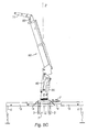
- Figure 10 shows the crane equipped to be installed on the three-point hitch of a tractor such as an agricultural tractor.
- the front of the base 1 has a double clevis 101 provided with of an axis receiving the end of the jack 102 for mounting in the point top of the hitch in three points of a tractor, both arms in part bottom of the hitch connecting to the legs 3.
- the tractor can be coupled to a seeder or a spreader fertilizer, the crane then becoming very useful for loading products in the seeder or spreader tank.
- This combination becomes all the more interesting as the current trend is to condition the products to be spread, in large and heavy lots sometimes of the order of a ton.
- the crane according to the invention can moreover advantageously replace the fork with two arms equipping some tractors.
- This allows congestion savings, increased efficiency and Versatility because, unlike the fork that can only be lifted around of a horizontal axis, in the longitudinal vertical plane of the tractor, the crane at the front (as also at the rear) of the tractor allows intervention practically 360 ° around its pivot axis. This freedom of movement facilitates loading and / or unloading operations.
- the crane makes it possible to equip the tractor different tools and in particular to mount a nacelle to perform work at height in plantations as hops or orchards, benefiting from the great stability assured by the weight of the tractor.
Abstract
Description
- un bras dont l'extrémité inférieure est articulée à l'embase et l'extrémité supérieure est articulée au pied du mât,
- un vérin de relevage monté entre l'embase et le bras pour basculer le bras vers l'arrière entre une position redressée et une position abaissée ou inversement,
- un vérin de déploiement monté entre le bras et le mât pour basculer le mât télescopique entre une position repliée contre le bras et une position déployée,
- le bras et le mât télescopique se repliant à plat l'un contre l'autre et l'abaissement par pivotement du bras permettant au bras télescopique de venir à plat sur le bras et au-dessus de l'embase, en position de rangement.
- la figure 1 est une vue en perspective d'une grue selon l'invention,
- la figure 2 est une vue de face de la grue de la figure 1,
- la figure 3 montre la grue de la figure 1 en position repliée,
- la figure 4A montre la grue prête à être installée sur le châssis d'un véhicule, en se limitant à l'embase sans le mât,
- la figure 4B est une vue en coupe horizontale selon IV-IV de la grue de la figure 4A,
- les figures 5A-5F montrent des exemples de différentes positions de déploiement de la grue,
- les figures 6A-6B montrent respectivement une vue de côté avec la grue déployée et la grue repliée,
- la figure 6C est une vue de face du véhicule,
- la figure 7 est une vue en perspective de l'arrière du châssis du véhicule portant la grue,
- les figures 8A-8C montrent trois exemples de positions d'utilisation :
- la figure 8A montre une vue arrière du véhicule muni de l'équipement, le bras étant en position d'utilisation comme excavatrice,
- la figure 8B montre le débattement latéral de la grue et la portée de la flèche munie du balancier,
- la figure 8C montre la grue en position relevée, par exemple en position de levage,
- la figure 9 est une vue de dessus du véhicule de la figure 8A,
- la figure 10 est une vue de la grue équipée de moyens de fixation pour être installée sur l'attelage en trois points d'un tracteur.
- à l'avant, en position repliée, la grue ne réduit pratiquement pas la visibilité,
- à l'arrière, la grue repliée ne réduit pas non plus la visibilité et, de plus, l'encombrement très réduit de la grue n'interdit pas l'installation d'autres équipements.
Claims (9)
- Grue à mât télescopique pour véhicule, notamment engin de chantier comprenant un mât télescopique porté par une embase tournante montée dans un socle installé sur le châssis du véhicule,
comprenantcaractérisée en ce queun bras (20) dont l'extrémité inférieure est articulée (83) à l'embase (8) et l'extrémité supérieure (22) est articulée (24) au pied (51) du mât (50),un vérin de relevage (30) monté entre l'embase (8) et le bras (20),un vérin de déploiement (40) monté entre le bras (20) et le mât (50),le bras (20) basculant vers l'arrière entre une position redressée et une position abaissée et inversement,le mât télescopique (50) basculant entre une position repliée contre le bras et une position déployée,le bras (20) et le mât télescopique (50) se replient à plat l'un contre l'autre etl'abaissement par pivotement du bras (20) permet au bras télescopique (50) de se replier à plat sur le bras et d'être rappelé au-dessus de l'embase (8), en position de rangement
le bras (20) est en forme de T avec une traverse de tête (22), le pied du bras étant articulé (83) à l'embase (8) et les extrémités de sa traverse de tête sont reliées l'une (23) au vérin de relevage (30) et l'autre (24) au pied (51) du mât (50),
le bras (20) se prolongeant au-delà de son articulation (83) avec l'embase (8) par un prolongement (25) portant l'articulation (26) du vérin de déploiement (40),
le bras (20) occupant une position médiane en étant flanqué de ces deux vérins (30, 40). - Grue selon la revendication 1,
caractérisée en ce que
l'embase (8) est en forme de double chape (81) logeant des joints tournants (701) pour alimenter les vérins du bras et du mât (30, 40, 56). - Grue selon la revendication 1,
caractérisée en ce que
l'embase (8) est reliée au socle (1) par un palier de pivotement en forme de couronne d'appui et d'entraínement (9). - Grue selon la revendication 1,
caractérisée en ce que
le bras (20) est formé de deux plaques jumelées. - Grue selon la revendication 1,
caractérisée en ce que
le pied (51) du mât (50) est formée de deux plaques reliées à un axe (24) porté par le bras (20) et pivotant entre les deux parties du bras (20). - Grue selon la revendication 1,
caractérisée en ce que
le mât télescopique (50) est formé d'au moins deux parties télescopiques (54, 55) commandées par un vérin (56) ainsi que d'une flèche (60) et d'un balancier (70) rétractables dans le mât (50), le balancier recevant l'outil. - Grue selon la revendication 1,
caractérisée en ce que
le mât télescopique (50) rétracté a une longueur sensiblement égale au gabarit transversal du véhicule auquel il est destiné. - Grue selon la revendication 1,
caractérisée en ce qu'
elle comprend un socle (1) ayant deux manchons (4) pour recevoir des branches extensibles (50) portant les béquilles (6) ainsi que des pattes (3) de montage rapide pour installer l'équipement sur le châssis d'un véhicule. - Grue selon la revendication 1,
caractérisée en ce qu'
elle comporte des chapes pour être installée sur l'attelage en trois points d'un tracteur de type tracteur agricole.
Applications Claiming Priority (2)
| Application Number | Priority Date | Filing Date | Title |
|---|---|---|---|
| FR0406452 | 2004-06-15 | ||
| FR0406452A FR2871455B1 (fr) | 2004-06-15 | 2004-06-15 | Grue a mat telescopique |
Publications (2)
| Publication Number | Publication Date |
|---|---|
| EP1607363A2 true EP1607363A2 (fr) | 2005-12-21 |
| EP1607363A3 EP1607363A3 (fr) | 2006-10-25 |
Family
ID=34949088
Family Applications (1)
| Application Number | Title | Priority Date | Filing Date |
|---|---|---|---|
| EP05300480A Withdrawn EP1607363A3 (fr) | 2004-06-15 | 2005-06-15 | Grue à mât télescopique |
Country Status (2)
| Country | Link |
|---|---|
| EP (1) | EP1607363A3 (fr) |
| FR (1) | FR2871455B1 (fr) |
Cited By (4)
| Publication number | Priority date | Publication date | Assignee | Title |
|---|---|---|---|---|
| EP2098474A2 (fr) * | 2008-03-05 | 2009-09-09 | Manitowoc Crane Companies, Inc. | Machine transportable |
| AT16249U1 (de) * | 2018-04-26 | 2019-05-15 | Fmg Fahrzeugbau Maschb Gmbh | Fahrzeug |
| CN112093633A (zh) * | 2020-09-28 | 2020-12-18 | 徐州市三森威尔矿山科技有限公司 | 一种可安全避让的限力补偿稳罐装置 |
| WO2022204760A1 (fr) * | 2021-03-30 | 2022-10-06 | The Dynamic Engineering Solution Pty Ltd | Grue |
Families Citing this family (3)
| Publication number | Priority date | Publication date | Assignee | Title |
|---|---|---|---|---|
| RU2456227C1 (ru) * | 2011-02-10 | 2012-07-20 | Федеральное государственное образовательное учреждение высшего профессионального образования Волгоградская государственная сельскохозяйственная академия | Механизм для поворота стрелы манипулятора |
| CN106986285B (zh) * | 2017-04-30 | 2022-07-26 | 安徽好运机械有限公司 | 一种用于伸缩臂越野车的倾翻机构 |
| RU195275U1 (ru) * | 2019-10-14 | 2020-01-22 | Акционерное Общество "Клинцовский автокрановый завод" | Механизм поворота рабочей платформы |
Citations (3)
| Publication number | Priority date | Publication date | Assignee | Title |
|---|---|---|---|---|
| FR2457240A1 (fr) * | 1979-05-22 | 1980-12-19 | Montgon Serge | Grue hydraulique associee a un vehicule porteur |
| FR2727658A1 (fr) * | 1994-12-05 | 1996-06-07 | Daumer Joseph | Materiel de levage et de manutention de charges diverses, associe a un vehicule |
| EP0763487A1 (fr) * | 1995-09-14 | 1997-03-19 | Geesink B.V. | Véhicule de ramassage d'ordures |
-
2004
- 2004-06-15 FR FR0406452A patent/FR2871455B1/fr not_active Expired - Fee Related
-
2005
- 2005-06-15 EP EP05300480A patent/EP1607363A3/fr not_active Withdrawn
Patent Citations (3)
| Publication number | Priority date | Publication date | Assignee | Title |
|---|---|---|---|---|
| FR2457240A1 (fr) * | 1979-05-22 | 1980-12-19 | Montgon Serge | Grue hydraulique associee a un vehicule porteur |
| FR2727658A1 (fr) * | 1994-12-05 | 1996-06-07 | Daumer Joseph | Materiel de levage et de manutention de charges diverses, associe a un vehicule |
| EP0763487A1 (fr) * | 1995-09-14 | 1997-03-19 | Geesink B.V. | Véhicule de ramassage d'ordures |
Cited By (9)
| Publication number | Priority date | Publication date | Assignee | Title |
|---|---|---|---|---|
| EP2098474A2 (fr) * | 2008-03-05 | 2009-09-09 | Manitowoc Crane Companies, Inc. | Machine transportable |
| EP2098474A3 (fr) * | 2008-03-05 | 2010-12-15 | Manitowoc Crane Companies, LLC | Machine transportable |
| US9440823B2 (en) | 2008-03-05 | 2016-09-13 | Manitowoc Crane Companies, Llc | Transportable machinery |
| AT16249U1 (de) * | 2018-04-26 | 2019-05-15 | Fmg Fahrzeugbau Maschb Gmbh | Fahrzeug |
| EP3560883A1 (fr) * | 2018-04-26 | 2019-10-30 | FMG Fahrzeugbau - Maschinenbau GmbH | Véhicule |
| CN112093633A (zh) * | 2020-09-28 | 2020-12-18 | 徐州市三森威尔矿山科技有限公司 | 一种可安全避让的限力补偿稳罐装置 |
| CN112093633B (zh) * | 2020-09-28 | 2023-08-04 | 徐州市三森威尔矿山科技有限公司 | 一种可安全避让的限力补偿稳罐装置 |
| WO2022204760A1 (fr) * | 2021-03-30 | 2022-10-06 | The Dynamic Engineering Solution Pty Ltd | Grue |
| GB2620537A (en) * | 2021-03-30 | 2024-01-10 | The Dynamic Eng Solution Pty Ltd | Crane |
Also Published As
| Publication number | Publication date |
|---|---|
| EP1607363A3 (fr) | 2006-10-25 |
| FR2871455A1 (fr) | 2005-12-16 |
| FR2871455B1 (fr) | 2008-03-14 |
Similar Documents
| Publication | Publication Date | Title |
|---|---|---|
| EP0733584B1 (fr) | Grue à montage automatisé avec flèche repliable sur elle-même | |
| EP1607363A2 (fr) | Grue à mât télescopique | |
| EP1965630B1 (fr) | Engin agricole comportant un attelage perfectionne | |
| EP0786201B1 (fr) | Robot taille-haies télécommandé avec réglage automatique des niveaux | |
| EP1031530B1 (fr) | Dispositif de dépliage ou repliage simultané d'éléments de pointe d'une flèche de grue | |
| FR2696070A1 (fr) | Herse rotative dont les poutres peuvent pivoter vers le haut pour le transport. | |
| EP1048605B1 (fr) | Grue avec flèche à fonctions multiples | |
| FR2688378A1 (fr) | Dispositif de relevage avant, pour tracteur agricole ou analogue, et porte-masse pour un tel dispositif. | |
| FR2722458A1 (fr) | Engin motorise de depannage, en particulier de char | |
| FR2472536A1 (fr) | Vehicule utilitaire a usages multiples | |
| FR2483731A2 (fr) | Machine agricole a structure repliable | |
| EP1243464A1 (fr) | Appareil de manutention d'une charge et véhicule le comportant | |
| EP1061034B1 (fr) | Chariot automoteur à bras télescopique et rehausse | |
| EP0873964B1 (fr) | Dispositif de relevage de mât pour grue à tour télescopique | |
| FR2544681A1 (fr) | Brouette a benne basculante | |
| EP1352870B1 (fr) | Dispositif de relevage et dépliage du mât et de relevage de la flêche d'une grue | |
| EP0113266B1 (fr) | Véhicule automobile mixte, notamment camion léger d'intervention rapide à pelle excavatrice | |
| FR2814038A1 (fr) | Dispositif de relevage pour tracteur permettant d'atteler et de deteler une masse sans intervention manuelle | |
| EP2959759B1 (fr) | Machine agricole munie d'un dispositif de centrage | |
| FR2610614A1 (fr) | Appareil elevateur articule | |
| FR3094177A1 (fr) | Dispositif de barrière repliable, notamment pour animaux | |
| FR2882621A1 (fr) | Andaineuse reversible | |
| FR2584351A1 (fr) | Engin de broyage-recuperation de produits forestiers a benne basculante et deposable | |
| FR2567092A1 (fr) | Tracto-pelle articule a usage agricole et de travaux publics | |
| FR3139973A1 (fr) | Machine agricole comportant une arche et un système de fixation particulier fixé à l’arche et assurant la fixation d’un outil |
Legal Events
| Date | Code | Title | Description |
|---|---|---|---|
| PUAI | Public reference made under article 153(3) epc to a published international application that has entered the european phase |
Free format text: ORIGINAL CODE: 0009012 |
|
| AK | Designated contracting states |
Kind code of ref document: A2 Designated state(s): AT BE BG CH CY CZ DE DK EE ES FI FR GB GR HU IE IS IT LI LT LU MC NL PL PT RO SE SI SK TR |
|
| AX | Request for extension of the european patent |
Extension state: AL BA HR LV MK YU |
|
| PUAL | Search report despatched |
Free format text: ORIGINAL CODE: 0009013 |
|
| AK | Designated contracting states |
Kind code of ref document: A3 Designated state(s): AT BE BG CH CY CZ DE DK EE ES FI FR GB GR HU IE IS IT LI LT LU MC NL PL PT RO SE SI SK TR |
|
| AX | Request for extension of the european patent |
Extension state: AL BA HR LV MK YU |
|
| RIC1 | Information provided on ipc code assigned before grant |
Ipc: B65F 3/02 20060101ALI20060919BHEP Ipc: B60P 1/54 20060101ALI20060919BHEP Ipc: B66C 23/36 20060101ALI20060919BHEP Ipc: B66C 23/70 20060101ALI20060919BHEP Ipc: B66C 23/68 20060101AFI20051022BHEP |
|
| AKX | Designation fees paid | ||
| REG | Reference to a national code |
Ref country code: DE Ref legal event code: 8566 |
|
| STAA | Information on the status of an ep patent application or granted ep patent |
Free format text: STATUS: THE APPLICATION IS DEEMED TO BE WITHDRAWN |
|
| 18D | Application deemed to be withdrawn |
Effective date: 20070426 |