EP1607309A2 - Verfahren zum Betrieb eines Lenksystems eines Kraftfahrzeugs - Google Patents
Verfahren zum Betrieb eines Lenksystems eines Kraftfahrzeugs Download PDFInfo
- Publication number
- EP1607309A2 EP1607309A2 EP05103865A EP05103865A EP1607309A2 EP 1607309 A2 EP1607309 A2 EP 1607309A2 EP 05103865 A EP05103865 A EP 05103865A EP 05103865 A EP05103865 A EP 05103865A EP 1607309 A2 EP1607309 A2 EP 1607309A2
- Authority
- EP
- European Patent Office
- Prior art keywords
- angle
- additional
- actuator
- steering
- steering system
- Prior art date
- Legal status (The legal status is an assumption and is not a legal conclusion. Google has not performed a legal analysis and makes no representation as to the accuracy of the status listed.)
- Granted
Links
Images

Classifications
-
- B—PERFORMING OPERATIONS; TRANSPORTING
- B62—LAND VEHICLES FOR TRAVELLING OTHERWISE THAN ON RAILS
- B62D—MOTOR VEHICLES; TRAILERS
- B62D5/00—Power-assisted or power-driven steering
- B62D5/008—Changing the transfer ratio between the steering wheel and the steering gear by variable supply of energy, e.g. by using a superposition gear
-
- B—PERFORMING OPERATIONS; TRANSPORTING
- B62—LAND VEHICLES FOR TRAVELLING OTHERWISE THAN ON RAILS
- B62D—MOTOR VEHICLES; TRAILERS
- B62D5/00—Power-assisted or power-driven steering
- B62D5/04—Power-assisted or power-driven steering electrical, e.g. using an electric servo-motor connected to, or forming part of, the steering gear
- B62D5/0457—Power-assisted or power-driven steering electrical, e.g. using an electric servo-motor connected to, or forming part of, the steering gear characterised by control features of the drive means as such
- B62D5/0481—Power-assisted or power-driven steering electrical, e.g. using an electric servo-motor connected to, or forming part of, the steering gear characterised by control features of the drive means as such monitoring the steering system, e.g. failures
Definitions
- the invention relates to a method for operating a Steering system of a motor vehicle.
- the invention also relates to a computer program and a computer program product with program code means, such a method for operating a steering system on a computer, especially on a microprocessor, a steering unit of the steering system and such a controller.
- the overlay means for example, other vehicle dynamics systems (e.g. Electronic Stability Program (ESP) or Anti-lock Braking System (ABS)).
- ESP Electronic Stability Program
- ABS Anti-lock Braking System
- a steering wheel angle superimpose speed-dependent additional angle. This can be done at low vehicle speeds set a relatively small gear ratio are, i. a relatively small turn of the Steering handle leads to a relatively large steering angle the wheels while at high vehicle speeds set a relatively large gear ratio can be, so that the driving stability of the motor vehicle elevated.
- the disadvantage is when the steering system itself or the too supporting further driving dynamics systems not over the actual available dynamics or functionality the superposition means or the actuator are informed.
- On the steering system or the actuator other influences, such as e.g. temperature or reaction moments and forces.
- This could Setpoints for superimposing additional angles and additional angular speeds, which not from the actuator could be realized - be it because of a malfunction or simply by the current driving situation (eg by the state of the internal combustion engine of the Motor vehicle) conditioned - both of the utility functions the steering system itself (eg variable steering ratio) as well as the other driving dynamics systems be avoided.
- the present invention is based on the object a method for operating a steering system, a computer program, a computer program product and a To provide control unit of the type mentioned, which the reliability, availability and reliability improve the steering system.
- the inventive method for operating a Steering systems are advantageously the dynamics or the functionality of the actuator for generating the Monitored additional angle.
- This information available can from the steering system and other driving dynamics systems (ESP, ASR, ABS, etc.) used what Overall, increased reliability and reliability of the steering system leads.
- ESP steering system and other driving dynamics systems
- a first function the status of the dynamics of the actuator using a Difference of a time course of a measured additional angle from a nominal model-based time history an additional angle of the actuator determined where the difference is each angle, angular velocity and angular acceleration is calculated.
- the first function gives the status of the dynamics of the actuator with "0” or “OK” if the Absolute values of all difference values of angle, angular velocity and angular acceleration smaller or equal to their corresponding predetermined thresholds and otherwise with "1" or “not in order” at.
- a preferred embodiment of the invention can be a real-time model of 2nd order as a dynamics model used for the actuator, which a setpoint of the additional angle as input receives and real-time model-based actual values for additional angle, additional angular velocity and additional angular acceleration calculated.
- control unit among other things, the setpoint of the additional angle, the additional angle, the pinion angle, the steering wheel angle and the vehicle speed as input variables, in particular of sensors or other vehicle systems receives or other input variables, in particular Wheel speeds by means of a suitable model, especially the steering system.
- the steering system has, in particular for controlling the Overlay means, an electronic control unit auf, on which the inventive method for Operation of the steering system expires.
- the control unit receives among others as input variables, the additional angle, the steering wheel angle, the pinion angle, the Vehicle speed or the like of sensors and / or other vehicle systems or calculates them Sizes due to other sizes of the steering system or of the motor vehicle. Due to these input variables then be corresponding electrical drive signals to control the superposition means determined.
- the method for operating a device according to the invention Steering system is advantageously as a computer program realized on the control unit of the steering system.
- the computer program is in a memory element stored on the controller.
- the procedure executed Through the processing on a microprocessor of the controller is the Procedure executed.
- the computer program can open a computer-readable medium (floppy disk, CD, DVD, Hard disk, USB memory stick, or the like) or an internet server stored as a computer program product be and from there into the memory element be transferred to the control unit.
- a steering system 1 of a motor vehicle is shown.
- the steering system 1 has a steering handle 2 designed as a steering wheel.
- the steering wheel 2 is connected via a hinge shaft 3 with a steering gear 4.
- the steering gear 4 serves to convert a rotational angle of the propeller shaft 3 in a steering angle ⁇ Fm of steerable wheels 5a, 5b of the motor vehicle.
- the steering gear 4 has a rack 6 and a pinion 7, to which the propeller shaft 3 engages.
- the steering system 1 further comprises superimposition means 8, which have an electric motor designed as an actuator 9 and driven by this superposition gear 10.
- the superposition gear is designed as a planetary gear 10.
- a steering wheel angle ⁇ S is given as a measure of a desired steering angle ⁇ Fm of the steerable wheels 5a, 5b of the motor vehicle.
- an additional angle ⁇ M is then generated and superposed by the superposition gear 10 with the steering wheel angle ⁇ S.
- the additional angle or motor angle ⁇ M is generated to improve the driving dynamics of the motor vehicle or the comfort.
- the sum of steering wheel angle ⁇ S and additional angle ⁇ M gives the pinion angle ⁇ G.
- Subordinate 8 could subordinate the superposition Steering system 1 in another embodiment in addition having a servo drive (not shown), which in particular the variable moment assistance serves as well as electrohydraulic Transducer is called.
- the servo drive includes a Hydraulic pump which a hydraulic fluid over a hydraulic valve is transported in the steering gear 4. About the hydraulic valve, the flow of Hydraulic fluid to one or the other end the rack 6 steered so as to provide appropriate torque support to effect in the desired direction. However, this is for the present invention not mandatory.
- the steering system 1 has an electronic control unit 11 which, among other things, serves to control the electric motor 9.
- the electric motor 9 with an electrical drive signal ⁇ Md , which corresponds to the desired value of the actuator 9 to be superimposed additional angle ⁇ M , driven.
- the control of the electric motor 9 takes place here as a function of the vehicle speed v X of the motor vehicle, ie the gear ratio between the steering wheel angle ⁇ S and the pinion angle ⁇ G and the steering angle ⁇ Fm of the wheels 5a, 5b by the superposition of the steering angle ⁇ S with different, speed-dependent additional angles ⁇ M as a function of the vehicle speed v X set.
- the control unit 11 receives as input the current vehicle speed v X (eg via the CAN bus of the motor vehicle).
- the steering system 1 sensors 12a, 12b, 12c which measure the steering wheel angle ⁇ S , the additional angle ⁇ M and the pinion angle ⁇ G. 1, the control unit 11 via the sensors 12a, 12b, 12c and other vehicle systems with the input signals steering wheel angle ⁇ S , pinion angle ⁇ G , current vehicle speed v X , additional angle ⁇ M , desired value of the additional angle ⁇ Md (z. B. of other vehicle dynamics systems), current temperature T (by a temperature sensor, not shown) and Zahnstangenhubverlauf l ⁇ supplied.
- a plurality of these variables could also be calculated on the basis of the other or further input variables (eg wheel speeds, etc.), in particular with the aid of suitable models.
- the controller 11 has as output signals a status value adyn stat for the dynamics of the actuator 9 and the estimated maximum available additional positive M_MAX_POS and negative M_MAX_NEG Additional angular speed of the actuator 9. These outputs are provided via a corresponding interface (via the CAN bus of the motor vehicle) to other vehicle dynamics systems, in particular ESP, ASR and ABS (not shown in more detail).
- the further dynamic dynamics systems have the maximum available dynamic reserve, ie the additional superimposing speed M_MAX_POS , M_MAX_NEG of the actuator 9 and the status value adyn stat informed the dynamics of the actuator 9.
- the vehicle dynamics systems can in turn adjust to these conditions in their controls or regulations and setpoint specifications ⁇ Md for the superposition means 8, whose implementation is not possible due to the maximum available dynamics of the actuator 9, for example, refrain from the outset.
- the output signals adyn_stat, M_MAX_POS and M_MAX_NEG are generated by the method according to the invention for operating a steering system.
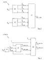
- a first safety function ADYN determines the status value adyn_stat for the dynamics of the actuator 9 and a second function DYNRES (see FIG. 3) the estimated maximum available additional positive ⁇ ⁇ M_MAX_POS and negative ⁇ ⁇ M_AMY_NEG auxiliary angular velocity of the actuator 9 ,
- a functional block 20 represents a non-linear, real-time model of the second order of the actuator 9 and receives as an input signal to be set on the actuator 9 setpoint of the additional angle ⁇ Md .
- the expected dynamics of the actuator 9 are model-based calculated from the time course of the desired value of the additional angle ⁇ Md . For this, the expected actual values for additional angles ( M ), additional angular velocity ( M ) and additional angular acceleration ( M ) and passed to another functional block 22.
- a function block 21 receives as input signal the currently set additional angle ⁇ M measured by the sensor 12b. This is filtered and derived according to the time.
- Function block 22 compares the model actual values M , M and M with the corresponding measured actual values ⁇ M_fil , M_fil and M_fil . The resulting difference values are compared in magnitude with predetermined threshold values. If the magnitudes of all difference values are less than or equal to the corresponding threshold value, output block adyn stat (electrical signal) "0" or "OK”, otherwise "1” or “not OK”, is output by function block 22.
- a function block 30 receives as an input signal the currently measured by the sensor 12b additional angle ⁇ M. This is filtered there and derived according to the time, so that as output signals the current, filtered additional angle ⁇ M_fil and the current speed of the filtered additional angle M_fil is output to a function block 31.
- the function block 31 additionally receives the current outside temperature T from a temperature sensor (not shown), since the outside temperature T also influences the steering system 1.
- the function block 31 represents a linear model for the electrical torque and determines from the input values ⁇ M_fil , M_fil and T as output signals the maximum positive and negative electrical moment M E_MAX_POS , M E_MAX_NEG of the actuator 9.
- the output signals M E_MAX_POS , M E_MAX_NEG be to a non-linear model of the mechanics of the steering system 1 formed further functional block 32 together with the outside temperature T, the current speed of the filtered additional angle M_fil and the Zahnstangenhubverlauf l ⁇ passed as input signals.
- estimates for the maximum additionally available additional angular velocity of the actuator 9 are generated and these with the current speed of the additional angle M_fil , after which the estimates for the maximum available additional positive M_MAX_POS and negative M_MAX_NEG additional angular velocity (superposition speed ) of the actuator 9 are determined as output signals .
- the sign of the additional target overlay velocity is independent of the sign of the current absolute overlay velocity, two different overlay velocities (positive / negative - depending on the current direction of rotation) must be estimated.
- the output signals M_MAX_POS , M_MAX_NEG can also be transformed into middle additional front wheel angular speeds and made available.
- the dynamics or the functionality of the actuator 9 for generating the additional angle ⁇ M are effectively monitored by the functions ADYN and DYNRES.
- the information provided can be used by a fault strategy of the steering system 1 and by other driving dynamics systems (ESP, ASR, ABS, etc.) as well as for diagnosis and long-term observation, which leads overall to increased reliability, availability and functional reliability of the steering system 1.
- the inventive method for operating the steering system 1 with the functions ADYN and DYNRES is in advantageously as a computer program on the control unit 11 realized.
- This is the computer program stored in a memory element of the controller 11 (not shown). Through the processing on a microprocessor of the controller 11 is the method running at every sampling step.
- the Computer program may be on a computer readable medium (Floppy disk, CD, DVD, hard disk, USB memory stick, or the like) or an Internet server be stored as a computer program product and from there into the memory element of the controller 11 are transmitted.
Landscapes
- Engineering & Computer Science (AREA)
- Chemical & Material Sciences (AREA)
- Combustion & Propulsion (AREA)
- Transportation (AREA)
- Mechanical Engineering (AREA)
- Steering Control In Accordance With Driving Conditions (AREA)
Abstract
Description
- Fig. 1
- ein Schema eines Überlagerungslenksystems, welches durch ein erfindungsgemäßes Verfahren betrieben wird;
- Fig. 2
- ein Schema einer ersten Funktion des erfindungsgemäßen Verfahrens zur Überwachung der Dynamik des Stellers; und
- Fig. 3
- ein Schema einer zweiten Funktion des erfindungsgemäßen Verfahrens zur Schätzung der Dynamikreserve des Stellantriebs.


Claims (10)
- Verfahren zum Betrieb eines Lenksystems (1) eines Kraftfahrzeugs, wobei1.1. eine Lenkhandhabe (2) einen Lenkradwinkel (δS) als Maß für einen gewünschten Lenkwinkel (δFm) für wenigstens ein lenkbares Rad (5a,5b) des Kraftfahrzeugs vorgibt, wobei1.2. ein Lenkgetriebe (4) mit einem Ritzel (7) einen von dem Lenkradwinkel (δS) abhängigen Ritzelwinkel (δG) in den Lenkwinkel (δFm) des wenigstens einen lenkbare Rades (5a,5b) des Kraftfahrzeugs umsetzt, wobei1.3. Überlagerungsmittel (8) einen Zusatzwinkel (δ M ) durch einen Stellantrieb (9) und den Ritzelwinkel (δG) aus einer Überlagerung des Lenkradwinkels (δS) mit dem Zusatzwinkel (δ M ) durch ein Überlagerungsgetriebe (10) erzeugen und wobei1.4. das Verfahren zum Betrieb des Lenksystems (1) und die Ansteuerung des Stellantriebs (9) durch ein Steuergerät (11) des Lenksystems (1) durchgeführt werden,
dadurch gekennzeichnet , dass1.5. wenigstens eine Funktion (ADYN,DYNRES) eine Dynamik des Stellantriebs (9) modellbasiert überwacht. - Verfahren nach Anspruch 1,
dadurch gekennzeichnet , dass
eine erste Funktion den Status (adyn stat) der Dynamik des Stellantriebs (9) anhand einer Differenz eines Zeitverlaufs eines gemessenen Zusatzwinkels (δ M ) von einem nominalen modellbasierten Zeitverlauf eines Zusatzwinkels (M ) des Stellantriebs (9) ermittelt, wobei die Differenz jeweils von Winkel, Winkelgeschwindigkeit und Winkelbeschleunigung berechnet wird.
- Verfahren nach Anspruch 2,
dadurch gekennzeichnet , dass
die erste Funktion den Status (adyn stat) der Dynamik des Stellantriebs (9) mit "0" bzw. "in Ordnung" angibt, wenn die Absolutbeträge aller Differenzwerte von Winkel, Winkelgeschwindigkeit und Winkelbeschleunigung kleiner oder gleich deren entsprechend vorgegebene Schwellwerte sind und andernfalls mit "1" bzw. "nicht in Ordnung" angibt. - Verfahren nach Anspruch 2 oder 3,
dadurch gekennzeichnet , dass
das Dynamikmodell (ADYN) einen Sollwert des Zusatzwinkels (δ Md ) als Eingangsgröße erhält und in Echtzeit modellbasierte Istwerte für Zusatzwinkel ( M ) berechnet.
- Verfahren nach Anspruch 1,
dadurch gekennzeichnet , dass
eine zweite Funktion (DYNRES) eine maximal positive und/oder negative verfügbare zusätzliche Zusatzwinkelgeschwindigkeit ( - Verfahren nach einem der Ansprüche 1 bis 5,
dadurch gekennzeichnet , dass
die Ausgaben der ersten (ADYN) oder der zweiten Funktion (DYNRES) bzw. der Status (adyn_stat) der Dynamik des Stellantriebs (9) oder die geschätzte maximal verfügbare zusätzliche positive und/oder negative Zusatzwinkelgeschwindigkeit (M_MAX_POS ,
- Verfahren nach einem der Ansprüche 1 bis 6,
dadurch gekennzeichnet , dass
das Steuergerät unter anderem den Sollwert des Zusatzwinkels (δ Md ), den Zusatzwinkel (δ M ), den Ritzelwinkel (δG), den Lenkradwinkel (δS) und die Fahrzeuggeschwindigkeit (vX) als Eingangsgrößen, insbesondere von Sensoren (12a,12b,12c) oder weiteren Fahrzeugsystemen erhält oder anhand anderer Eingangsgrößen, insbesondere Raddrehzahlen mittels eines geeigneten Modells, insbesondere des Lenksystems (1) berechnet. - Computerprogramm mit Programmcodemitteln, um ein Verfahren zum Betrieb eines Lenksystems (1) gemäß einem der Ansprüche 1 bis 7 durchzuführen, wenn dass Programm auf einem Mikroprozessor eines Computers, insbesondere auf dem Steuergerät (11) des Lenksystems (1), ausgeführt wird.
- Computerprogrammprodukt mit Programmcodemitteln, die auf einem computerlesbaren Datenträger gespeichert sind, um ein Verfahren zum Betrieb eines servounterstützten Lenksystems (1) gemäß einem der Ansprüche 1 bis 7 durchzuführen, wenn dass Programm auf einem Mikroprozessor eines Computers, insbesondere auf dem Steuergerät (11) des Lenksystems (1), ausgeführt wird.
- Steuergerät (11) für ein Lenksystem (1) eingerichtet zur Ausführung eines Computerprogramms gemäß Anspruch 8.
Applications Claiming Priority (2)
| Application Number | Priority Date | Filing Date | Title |
|---|---|---|---|
| DE102004028828 | 2004-06-15 | ||
| DE102004028828A DE102004028828A1 (de) | 2004-06-15 | 2004-06-15 | Verfahren zum Betrieb eines Lenksystems eines Kraftfahrzeugs |
Publications (3)
| Publication Number | Publication Date |
|---|---|
| EP1607309A2 true EP1607309A2 (de) | 2005-12-21 |
| EP1607309A3 EP1607309A3 (de) | 2006-04-19 |
| EP1607309B1 EP1607309B1 (de) | 2008-03-19 |
Family
ID=34939761
Family Applications (1)
| Application Number | Title | Priority Date | Filing Date |
|---|---|---|---|
| EP05103865A Expired - Lifetime EP1607309B1 (de) | 2004-06-15 | 2005-05-10 | Verfahren zum Betrieb eines Lenksystems eines Kraftfahrzeugs |
Country Status (3)
| Country | Link |
|---|---|
| US (1) | US7676308B2 (de) |
| EP (1) | EP1607309B1 (de) |
| DE (2) | DE102004028828A1 (de) |
Cited By (5)
| Publication number | Priority date | Publication date | Assignee | Title |
|---|---|---|---|---|
| DE102008036039A1 (de) * | 2008-08-01 | 2010-03-04 | Bayerische Motoren Werke Aktiengesellschaft | Verfahren zur Überwachung und Ansteuerung eines Positions-Stellers |
| US9868445B2 (en) | 2015-08-14 | 2018-01-16 | Crown Equipment Corporation | Diagnostic supervisor to determine if a traction system is in a fault condition |
| US10414288B2 (en) | 2017-01-13 | 2019-09-17 | Crown Equipment Corporation | Traction speed recovery based on steer wheel dynamic |
| US10723382B2 (en) | 2017-01-13 | 2020-07-28 | Crown Equipment Corporation | High speed straight ahead tiller desensitization |
| US11008037B2 (en) | 2015-08-14 | 2021-05-18 | Crown Equipment Corporation | Model based diagnostics based on steering model |
Families Citing this family (3)
| Publication number | Priority date | Publication date | Assignee | Title |
|---|---|---|---|---|
| DE102006008156A1 (de) * | 2006-02-22 | 2007-08-23 | Wabco Gmbh | Verfahren zur Bestimmung der Lenkübersetzung eines Fahrzeugs |
| DE102009002743B4 (de) * | 2009-04-30 | 2022-02-10 | Ford Global Technologies, Llc | Verfahren zum Betreiben eines aktiven Lenksystems sowie aktives Lenksystem |
| CN107036596B (zh) * | 2017-04-12 | 2020-01-10 | 无锡研测技术有限公司 | 基于mems惯性传感器模组的工业手环 |
Citations (1)
| Publication number | Priority date | Publication date | Assignee | Title |
|---|---|---|---|---|
| DE19751125A1 (de) | 1997-03-22 | 1998-09-24 | Bosch Gmbh Robert | Verfahren und Vorrichtung zum Betrieb eines Lenksystems für ein Kraftfahrzeug |
Family Cites Families (12)
| Publication number | Priority date | Publication date | Assignee | Title |
|---|---|---|---|---|
| DE19749005A1 (de) * | 1997-06-30 | 1999-01-07 | Bosch Gmbh Robert | Verfahren und Vorrichtung zur Regelung von die Fahrzeugbewegung repräsentierenden Bewegungsgrößen |
| DE19905433B4 (de) * | 1999-02-10 | 2011-11-10 | Robert Bosch Gmbh | Aktives Lenksystem |
| DE10012133A1 (de) * | 2000-03-13 | 2001-09-27 | Bosch Gmbh Robert | Überwachungssystem zur Überwachung einer Stelleinrichtung im Kraftfahrzeug |
| DE10032340A1 (de) * | 2000-07-04 | 2002-01-31 | Bosch Gmbh Robert | Verfahren zum Lenken eines Fahrzeugs mit Servolenkung |
| DE10045385A1 (de) * | 2000-09-14 | 2002-03-28 | Bayerische Motoren Werke Ag | Vorrichtung und Verfahren zur elektronischen Steuerung eines einem Regelsystem zugeordneten Aktuators in Kraftfahrzeugen |
| JP3908074B2 (ja) * | 2002-04-08 | 2007-04-25 | アイシン精機株式会社 | 電動ステアリング制御装置、及び該装置を有する車両のアンチスキッド制御装置 |
| DE10325484A1 (de) * | 2002-09-06 | 2004-03-25 | Continental Teves Ag & Co. Ohg | Verfahren zum Lenken eines Fahrzeugs mit einer Überlagerungslenkung |
| JP3908144B2 (ja) * | 2002-10-11 | 2007-04-25 | 株式会社ジェイテクト | ステアリング制御装置 |
| JP4604566B2 (ja) * | 2004-06-17 | 2011-01-05 | 日産自動車株式会社 | 車両用操舵装置 |
| JP4421426B2 (ja) * | 2004-08-31 | 2010-02-24 | 本田技研工業株式会社 | 操舵装置 |
| US7264080B2 (en) * | 2005-02-04 | 2007-09-04 | Delphi Technologies, Inc. | Electric preload for variable effort steering system |
| US7383112B2 (en) * | 2006-03-10 | 2008-06-03 | Gm Global Technology Operations, Inc. | Method and system for adaptively compensating open loop front-wheel steering control |
-
2004
- 2004-06-15 DE DE102004028828A patent/DE102004028828A1/de not_active Withdrawn
-
2005
- 2005-05-10 DE DE502005003271T patent/DE502005003271D1/de not_active Expired - Lifetime
- 2005-05-10 EP EP05103865A patent/EP1607309B1/de not_active Expired - Lifetime
- 2005-05-19 US US11/134,817 patent/US7676308B2/en not_active Expired - Fee Related
Patent Citations (1)
| Publication number | Priority date | Publication date | Assignee | Title |
|---|---|---|---|---|
| DE19751125A1 (de) | 1997-03-22 | 1998-09-24 | Bosch Gmbh Robert | Verfahren und Vorrichtung zum Betrieb eines Lenksystems für ein Kraftfahrzeug |
Cited By (9)
| Publication number | Priority date | Publication date | Assignee | Title |
|---|---|---|---|---|
| DE102008036039A1 (de) * | 2008-08-01 | 2010-03-04 | Bayerische Motoren Werke Aktiengesellschaft | Verfahren zur Überwachung und Ansteuerung eines Positions-Stellers |
| DE102008036039B4 (de) * | 2008-08-01 | 2010-07-22 | Bayerische Motoren Werke Aktiengesellschaft | Verfahren zur Überwachung und Ansteuerung eines Positions-Stellers |
| US9868445B2 (en) | 2015-08-14 | 2018-01-16 | Crown Equipment Corporation | Diagnostic supervisor to determine if a traction system is in a fault condition |
| US10081367B2 (en) | 2015-08-14 | 2018-09-25 | Crown Equipment Corporation | Steering and traction applications for determining a steering control attribute and a traction control attribute |
| US10377388B2 (en) | 2015-08-14 | 2019-08-13 | Crown Equipment Corporation | Model based diagnostics based on traction model |
| US11008037B2 (en) | 2015-08-14 | 2021-05-18 | Crown Equipment Corporation | Model based diagnostics based on steering model |
| US10414288B2 (en) | 2017-01-13 | 2019-09-17 | Crown Equipment Corporation | Traction speed recovery based on steer wheel dynamic |
| US10723382B2 (en) | 2017-01-13 | 2020-07-28 | Crown Equipment Corporation | High speed straight ahead tiller desensitization |
| US11400975B2 (en) | 2017-01-13 | 2022-08-02 | Crown Equipment Corporation | High speed straight ahead tiller desensitization |
Also Published As
| Publication number | Publication date |
|---|---|
| DE502005003271D1 (de) | 2008-04-30 |
| US7676308B2 (en) | 2010-03-09 |
| DE102004028828A1 (de) | 2006-01-05 |
| EP1607309B1 (de) | 2008-03-19 |
| US20060021821A1 (en) | 2006-02-02 |
| EP1607309A3 (de) | 2006-04-19 |
Similar Documents
| Publication | Publication Date | Title |
|---|---|---|
| EP3595958B1 (de) | Schätzung der zahnstangenkraft in einem steer-by-wire system | |
| EP3496995B1 (de) | Regelung eines steer-by-wire-lenksystems | |
| EP3856611B1 (de) | Verfahren zum ermitteln einer zahnstangenkraft eines steer-by-wire-lenksystems, steer-by-wire-lenksystem und fahrzeug | |
| EP2077959B1 (de) | Verfahren zur Regelung oder Steuerung einer Servoantriebseinheit in einem Lenksystem eines Fahrzeugs und entsprechendes Lenksystem | |
| WO2019106070A1 (de) | Verfahren zur steuerung eines steer-by-wire-lenksystems mit active return | |
| DE10247975B4 (de) | Verfahren zum Betreiben einer Lenkung, ein Computerprogramm, ein Steuergerät sowie eine Lenkung für ein Fahrzeug | |
| WO2021058405A1 (de) | Verfahren und vorrichtung zur simultanen lateralen fahrzeugführung durch fahrer und assistenzsystem bei elektrischen lenkaktoren | |
| EP1607309B1 (de) | Verfahren zum Betrieb eines Lenksystems eines Kraftfahrzeugs | |
| DE102008038891B4 (de) | Vorrichtung und Verfahren zur Erfassung eines Drehmomentes an einer elektromechanischen Lenkung | |
| DE102007053818A1 (de) | Verfahren zum Betrieb einer Lenkeinrichtung mit variablem Übersetzungsverhältnis sowie Lenkeinrichtung zur Durchführung des Verfahrens | |
| EP4155170B1 (de) | Lenksystem und verfahren zum betreiben eines lenksystems | |
| DE102009009448B4 (de) | Verfahren und Vorrichtung zur Eigendiagnose mindestens einer zu diagnostizierenden Sensoreinheit einer elektromechanischen Lenkung | |
| DE102013011283A1 (de) | Verfahren und Vorrichtung zum Betreiben eines Lenksystems eines Kraftfahrzeugs | |
| DE19720440B4 (de) | Verfahren zur Regelung einer dynamischen Zustandsgröße eines Fahrzeugs | |
| EP1970289B1 (de) | Verfahren zum Betrieb einer elektrischen Servolenkvorrichtung | |
| DE102004060053A1 (de) | Servolenkung und Verfahren zur Fahrerunterstützung bei seiner Lenktätigkeit | |
| DE102020108132A1 (de) | Traktionslenkungsabschwächung durch cvr-verstärkungsskalare | |
| DE102017214581B4 (de) | Verfahren zum Betrieb eines Lenksystems | |
| EP1955924B1 (de) | Verfahren zum Betrieb eines Lenksystems in einem Kraftfahrzeug | |
| DE102006040443B4 (de) | Verfahren zum Betrieb eines elektronisch geregelten Servolenksystems | |
| DE102010049431B4 (de) | Verfahren zur Diagnose mindestens einer zu diagnostizierenden Sensoreinheit einer elektromechanischen Lenkung und elektromechanische Lenkung | |
| EP1568575B1 (de) | Verfahren zum Betrieb eines Lenksystems mit Konfiguration von Nutzanwendungen | |
| EP1607308A2 (de) | Servounterstütztes Lenksystem eines Kraftfahrzeugs | |
| DE102005016514B4 (de) | Verfahren zur Überwachung der Rotorlage eines Elektromotors | |
| DE102008021847B4 (de) | Elektromechanisches Lenksystem und Verfahren zur Steuerung eines elektromechanischen Lenksystems |
Legal Events
| Date | Code | Title | Description |
|---|---|---|---|
| PUAI | Public reference made under article 153(3) epc to a published international application that has entered the european phase |
Free format text: ORIGINAL CODE: 0009012 |
|
| AK | Designated contracting states |
Kind code of ref document: A2 Designated state(s): AT BE BG CH CY CZ DE DK EE ES FI FR GB GR HU IE IS IT LI LT LU MC NL PL PT RO SE SI SK TR |
|
| AX | Request for extension of the european patent |
Extension state: AL BA HR LV MK YU |
|
| PUAL | Search report despatched |
Free format text: ORIGINAL CODE: 0009013 |
|
| AK | Designated contracting states |
Kind code of ref document: A3 Designated state(s): AT BE BG CH CY CZ DE DK EE ES FI FR GB GR HU IE IS IT LI LT LU MC NL PL PT RO SE SI SK TR |
|
| AX | Request for extension of the european patent |
Extension state: AL BA HR LV MK YU |
|
| RIC1 | Information provided on ipc code assigned before grant |
Ipc: B62D 113/00 20060101ALN20050926BHEP Ipc: B62D 153/00 00000000ALN20050926BHEP Ipc: B62D 6/00 20060101AFI20050926BHEP Ipc: B62D 113/00 20060101ALI20060227BHEP Ipc: B62D 137/00 20060101ALN20050926BHEP Ipc: B62D 137/00 20060101ALI20060227BHEP |
|
| 17P | Request for examination filed |
Effective date: 20060515 |
|
| GRAP | Despatch of communication of intention to grant a patent |
Free format text: ORIGINAL CODE: EPIDOSNIGR1 |
|
| RIC1 | Information provided on ipc code assigned before grant |
Ipc: B62D 6/00 20060101AFI20060818BHEP Ipc: B62D 137/00 20060101ALI20060818BHEP Ipc: B62D 113/00 20060101ALI20060818BHEP |
|
| AKX | Designation fees paid |
Designated state(s): DE ES FR GB IT SE |
|
| GRAS | Grant fee paid |
Free format text: ORIGINAL CODE: EPIDOSNIGR3 |
|
| GRAA | (expected) grant |
Free format text: ORIGINAL CODE: 0009210 |
|
| AK | Designated contracting states |
Kind code of ref document: B1 Designated state(s): DE ES FR GB IT SE |
|
| REG | Reference to a national code |
Ref country code: GB Ref legal event code: FG4D Free format text: NOT ENGLISH |
|
| REF | Corresponds to: |
Ref document number: 502005003271 Country of ref document: DE Date of ref document: 20080430 Kind code of ref document: P |
|
| ET | Fr: translation filed | ||
| PG25 | Lapsed in a contracting state [announced via postgrant information from national office to epo] |
Ref country code: ES Free format text: LAPSE BECAUSE OF FAILURE TO SUBMIT A TRANSLATION OF THE DESCRIPTION OR TO PAY THE FEE WITHIN THE PRESCRIBED TIME-LIMIT Effective date: 20080630 Ref country code: SE Free format text: LAPSE BECAUSE OF FAILURE TO SUBMIT A TRANSLATION OF THE DESCRIPTION OR TO PAY THE FEE WITHIN THE PRESCRIBED TIME-LIMIT Effective date: 20080619 |
|
| PLBE | No opposition filed within time limit |
Free format text: ORIGINAL CODE: 0009261 |
|
| STAA | Information on the status of an ep patent application or granted ep patent |
Free format text: STATUS: NO OPPOSITION FILED WITHIN TIME LIMIT |
|
| 26N | No opposition filed |
Effective date: 20081222 |
|
| PG25 | Lapsed in a contracting state [announced via postgrant information from national office to epo] |
Ref country code: IT Free format text: LAPSE BECAUSE OF FAILURE TO SUBMIT A TRANSLATION OF THE DESCRIPTION OR TO PAY THE FEE WITHIN THE PRESCRIBED TIME-LIMIT Effective date: 20080319 |
|
| GBPC | Gb: european patent ceased through non-payment of renewal fee |
Effective date: 20090510 |
|
| PG25 | Lapsed in a contracting state [announced via postgrant information from national office to epo] |
Ref country code: GB Free format text: LAPSE BECAUSE OF NON-PAYMENT OF DUE FEES Effective date: 20090510 |
|
| PGFP | Annual fee paid to national office [announced via postgrant information from national office to epo] |
Ref country code: FR Payment date: 20130531 Year of fee payment: 9 |
|
| REG | Reference to a national code |
Ref country code: FR Ref legal event code: ST Effective date: 20150130 |
|
| PG25 | Lapsed in a contracting state [announced via postgrant information from national office to epo] |
Ref country code: FR Free format text: LAPSE BECAUSE OF NON-PAYMENT OF DUE FEES Effective date: 20140602 |
|
| REG | Reference to a national code |
Ref country code: DE Ref legal event code: R081 Ref document number: 502005003271 Country of ref document: DE Owner name: ROBERT BOSCH AUTOMOTIVE STEERING GMBH, DE Free format text: FORMER OWNER: ZF LENKSYSTEME GMBH, 73527 SCHWAEBISCH GMUEND, DE Effective date: 20150423 |
|
| PGFP | Annual fee paid to national office [announced via postgrant information from national office to epo] |
Ref country code: DE Payment date: 20180725 Year of fee payment: 14 |
|
| REG | Reference to a national code |
Ref country code: DE Ref legal event code: R119 Ref document number: 502005003271 Country of ref document: DE |
|
| PG25 | Lapsed in a contracting state [announced via postgrant information from national office to epo] |
Ref country code: DE Free format text: LAPSE BECAUSE OF NON-PAYMENT OF DUE FEES Effective date: 20191203 |