EP1607306A2 - Verfahren und Vorrichtung zur Lenkunterstützung in Untersteuersituationen - Google Patents
Verfahren und Vorrichtung zur Lenkunterstützung in Untersteuersituationen Download PDFInfo
- Publication number
- EP1607306A2 EP1607306A2 EP05103271A EP05103271A EP1607306A2 EP 1607306 A2 EP1607306 A2 EP 1607306A2 EP 05103271 A EP05103271 A EP 05103271A EP 05103271 A EP05103271 A EP 05103271A EP 1607306 A2 EP1607306 A2 EP 1607306A2
- Authority
- EP
- European Patent Office
- Prior art keywords
- steering angle
- steering
- target
- act
- abs
- Prior art date
- Legal status (The legal status is an assumption and is not a legal conclusion. Google has not performed a legal analysis and makes no representation as to the accuracy of the status listed.)
- Granted
Links
Images


Classifications
-
- B—PERFORMING OPERATIONS; TRANSPORTING
- B62—LAND VEHICLES FOR TRAVELLING OTHERWISE THAN ON RAILS
- B62D—MOTOR VEHICLES; TRAILERS
- B62D6/00—Arrangements for automatically controlling steering depending on driving conditions sensed and responded to, e.g. control circuits
- B62D6/002—Arrangements for automatically controlling steering depending on driving conditions sensed and responded to, e.g. control circuits computing target steering angles for front or rear wheels
- B62D6/003—Arrangements for automatically controlling steering depending on driving conditions sensed and responded to, e.g. control circuits computing target steering angles for front or rear wheels in order to control vehicle yaw movement, i.e. around a vertical axis
-
- B—PERFORMING OPERATIONS; TRANSPORTING
- B62—LAND VEHICLES FOR TRAVELLING OTHERWISE THAN ON RAILS
- B62D—MOTOR VEHICLES; TRAILERS
- B62D15/00—Steering not otherwise provided for
- B62D15/02—Steering position indicators ; Steering position determination; Steering aids
- B62D15/025—Active steering aids, e.g. helping the driver by actively influencing the steering system after environment evaluation
-
- B—PERFORMING OPERATIONS; TRANSPORTING
- B62—LAND VEHICLES FOR TRAVELLING OTHERWISE THAN ON RAILS
- B62D—MOTOR VEHICLES; TRAILERS
- B62D6/00—Arrangements for automatically controlling steering depending on driving conditions sensed and responded to, e.g. control circuits
- B62D6/008—Control of feed-back to the steering input member, e.g. simulating road feel in steer-by-wire applications
-
- B—PERFORMING OPERATIONS; TRANSPORTING
- B60—VEHICLES IN GENERAL
- B60W—CONJOINT CONTROL OF VEHICLE SUB-UNITS OF DIFFERENT TYPE OR DIFFERENT FUNCTION; CONTROL SYSTEMS SPECIALLY ADAPTED FOR HYBRID VEHICLES; ROAD VEHICLE DRIVE CONTROL SYSTEMS FOR PURPOSES NOT RELATED TO THE CONTROL OF A PARTICULAR SUB-UNIT
- B60W2540/00—Input parameters relating to occupants
- B60W2540/18—Steering angle
Definitions
- the invention relates to a method for stabilizing a vehicle in one understeering driving condition.
- the assist torque automatically turns the steering wheel (and therefore the wheels) even if the driver does not apply torque to the steering wheel or release the steering wheel.
- the assist torque facilitates or complicates the driver's steering movement. This affects the "steering feel" of the driver. This makes it possible to guide the driver to the correct steering angle.
- a patronizing of the driver should be excluded.
- An advantageous embodiment of the invention is characterized in that the steering angle and the Ziellenkwinkel are each related to the front wheels.
- An advantageous embodiment of the invention is characterized in that the Ziellenkwinkel at least from the vehicle speed and the yaw rate is determined.
- the vehicle speed is determined in all vehicles that Yaw rate is in the context of a vehicle dynamics control in many modern Vehicles available as standard. Therefore, for this embodiment is not essential Additional effort necessary.
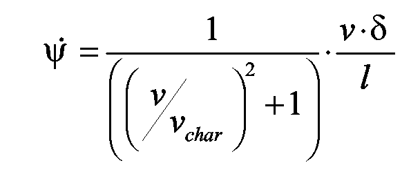
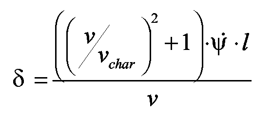
- An advantageous embodiment of the invention is characterized in that the Ziellkwinkel based on the relationship where ⁇ ⁇ is the current yaw rate, v is the current speed, v char is the characteristic speed, and l is the wheelbase of the vehicle. This relationship is mathematically easy to evaluate in the control unit, since this is an explicit calculation rule for the Ziellenkwinkel.
- An advantageous embodiment of the invention is characterized in that the Support torque proportional to the difference between the current steering angle and increases the present at the time of activation of the method steering angle. As a result, the size of the assist torque can be easily determined (because it's a linear function).
- An advantageous embodiment of the invention is characterized in that the Reduction of the assist torque in the second time interval is such that the Support torque proportional to the difference between the current steering angle and decreases the Ziellenkwinkel.
- the here proposed linear relationship between Torque and steering angle are particularly easy to implement in a control unit.
- An advantageous embodiment of the invention is characterized in that a Deactivation of the procedure then takes place when the driver turns the steering wheel during a Time interval of predetermined length against that by the assist torque rotates predetermined direction of rotation. From the time criterion can be concluded that the Driver of the assistance function deliberately does not want to follow. The deactivation becomes a Overconfidence of the driver's request prevented.
- An advantageous embodiment of the invention is characterized in that at a Deactivation of the process built up to the time of deactivation Support moment is reduced such that both the temporal moment course as Also, the time course of the torque change per unit time continuous functions of time are. This improves the steering feel for the driver.
- the invention comprises a device for carrying out the inventive Process.
- the current yaw rate of the vehicle is less than the yaw rate required by the driver over the steering (and vehicle speed).
- the reason is that the driver pulls the steering too far, ie increases the steering angle, and that the required forces can not be transferred to the road via the front tires.
- the vehicle slides over the front axle to the outside of the curve, ie in the direction outward.
- the understeer functionality is intended to control the servo motor of the steering so that the driver is helped to stabilize the vehicle in understeering driving situations. For this purpose, a moment is given to the steering, which should motivate the driver to open the steering, ie to reduce the steering angle. This achieves a better contact of the tires with the road surface and thus a more favorable direction of force action of the front wheels. The forces transmitted to the road are higher and better cornering is possible.
- the torque application supports the driver in a critical understeer situation. If the driver follows the instructions he receives about the torque assistance, a stabilization of the vehicle and a better cornering is achieved. This is especially helpful for inexperienced drivers, who usually intuitively continue to pull the steering (ie increase the steering angle), which leads to a worsening of the driving situation.
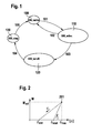
- the functionality of the steering assistance is distributed over different states of a state machine. This allows support in the critical driving situations, but also to respond to the behavior and the reaction of the driver on the torque application. Thus, an optimal support can be made and at the same time it is ensured that the driver has full control of the steering and thus the vehicle and is not overruled by the torque application. This functionality is depicted in the state machine shown in FIG.
- a tightening of the steering is determined if the amount of the current steering angle is greater than that of the last calculation step (condition I).
- condition I the torque line I.
- ⁇ start denotes the steering angle present at the beginning of the state USS_active.
- the Ziellkwinkel ⁇ target is estimated by any suitable method from the current driving dynamics measurements and model sizes. A way to determine the size ⁇ goal based on the inverse Ackermann relationship is presented later.
- ⁇ act_abs (k) is the current steering angle and ⁇ is the target steering angle.
- M (k-1) is the moment of the last calculation step. If the driver has opened the steering up to the steering angle ⁇ goal , the system returns to the USS_inactive state.
- the function recognizes via an arbitrarily suitable method that the driver does not comply with the suggestion of the assistance function, the function changes to the state USS_turnoff. In this mode, the switched-on torque is appropriately removed, regardless of the current driving situation.
- the inverse Ackermann equation can be used to set the steering angle ⁇ target , up to which the steering must be opened to leave the critical driving condition.
- the inverse Ackermann equation provides from the current yaw rate the steering angle at which the tires better contact with the road surface and thus a cheaper Force acting direction of the front wheels own. This will be the on the road transmitted forces increased and better cornering is possible, resulting in a Stabilization of understeer leads.
- the Ackermann equation (one-track model) and represents a relationship between the yaw rate and the steering angle:
- This equation yields, for ⁇ ⁇ , the current yaw rate, v the current speed, v char the characteristic speed, and l the wheelbase of the vehicle, a steering angle at which the vehicle left the critical state.
- This value is therefore suitable as a termination criterion (eg as a so-called target steering angle ⁇ target ) for active steering systems.
- the temporal course of the torque removal is a polynomial function of second order, i.e. the moment M is reduced according to a parabola function.
- a sudden or linear momentum removal improves the steering feel for the Driver, since there are no moment jumps and no jumps in the moment gradient.
- ⁇ M (k) can also be the size ⁇ M (k) as a gradient are designated, because ⁇ M (k) is proportional to ⁇ M (k) / ⁇ t. This increases the Clarity of the following formulas.
- the scanning step k is in the abscissa direction shown.
- the value k is proportional to the time t.
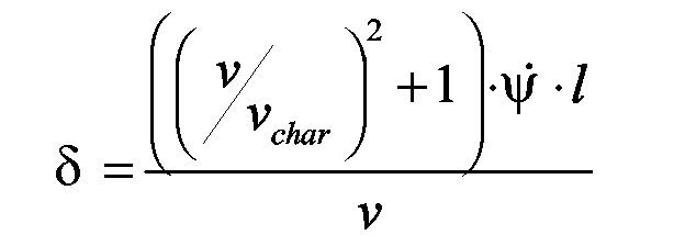
- FIG. 6 The sequence of the method according to the invention is shown in FIG. 6. After the start in block 600, it is determined in block 601 whether there is an understeer driving condition and the driver turns the steering wheel in the wrong direction. If the answer is "no" (always denoted by “n” in FIG. 6) then branched back to block 600. On the other hand, if the answer is "y”, then move to block 601. In block 602, the target steering angle ⁇ target is determined. Subsequently, the assistance torque M is determined in block 603, which predefines the steering wheel a direction of rotation, which leads to vehicle stabilization. In block 604 it is then queried whether the Ziellenkwinkel is reached. If the answer is no, then the input is returned to block 602.
- the structure of the device according to the invention is shown in FIG.
- the controller 703 contains input signals from one or more sensors 700. These allow after Evaluation the determination of an understeering driving condition. At the same time it receives Control unit 703 Input signals from the steering angle sensor 701. These signals can be next to the Steering angle also include other variables such as steering angle change speed, etc. These signals allow the controller to recognize the driver's request or the Driver reaction. Depending on these input signals, 703 controls one or more actuators 702 on which the steering wheel and / or the steering with a support torque apply. This allows haptic feedback to the driver.
Landscapes
- Engineering & Computer Science (AREA)
- Chemical & Material Sciences (AREA)
- Combustion & Propulsion (AREA)
- Transportation (AREA)
- Mechanical Engineering (AREA)
- Physics & Mathematics (AREA)
- Mathematical Physics (AREA)
- Steering Control In Accordance With Driving Conditions (AREA)
- Vehicle Body Suspensions (AREA)
Abstract
- ein Ziellenkwinkel (δziel) ermittelt wird,
- bei einer Lenkbewegung des Fahrers, welche die Differenz zwischen dem aktuellen Lenkwinkel (δact_abs) und dem Ziellenkwinkel (δziel) vergrößert, ein mit zunehmender Differenz größer werdendes Unterstützungsdrehmoment (M) auf das Lenkrad aufgebracht wird, und
- bei einer Lenkbewegung des Fahrers, welche die Differenz zwischen dem aktuellen Lenkwinkel (δact_abs) und dem Ziellenkwinkel (δziel) verringert, ein mit abnehmender Differenz kleiner werdendes Unterstützungsdrehmoment (M) auf das Lenkrad aufgebracht wird,
- wobei das Unterstützungsdrehmoment (M) dem Lenkrad eine Drehrichtung vorgibt und
- wobei bei einer Drehbewegung des Lenkrads durch den Fahrer in Richtung der vorgegebenen Drehrichtung der Lenkwinkel (δact_abs) und dem Ziellenkwinkel (δziel) angenähert wird.
Description
Eine weitere aktive Lenkung ist die elektrische Servolenkung. Bei dieser wird das vom Fahrer auf die Lenkung gebrachte Lenkmoment gemessen, ausgewertet und von einem Elektromotor ein entsprechendes Unterstützungsmoment über ein Schneckengetriebe auf die Zahnstange aufgebracht.
Durch gezielte Ansteuerung dieses Elektromotors hat man die Möglichkeit ein vom Fahrer unabhängiges Moment auf die Lenkung zu geben. Dieser nimmt diese Momentenaufschaltung im Lenkrad wahr. Bewegt der Fahrer das Lenkrad entgegen dem aufgebrachten Moment, muss er mehr Kraft aufbringen, das Lenkrad zu drehen. Im entgegengesetzten Fall unterstützt das aufgeschaltete Moment die Bewegung des Fahrers.
- ein Ziellenkwinkel ermittelt wird,
- bei einer Lenkbewegung des Fahrers, welche die Differenz zwischen dem aktuellen Lenkwinkel und dem Ziellenkwinkel vergrößert, ein mit zunehmender Differenz größer werdendes Unterstützungsdrehmoment bzw. Unterstützungsmoment bzw. fahrerunabhängiges Lenkmoment auf das Lenkrad aufgebracht wird,
- bei einer Lenkbewegung des Fahrers, welche die Differenz zwischen dem aktuellen Lenkwinkel und dem Ziellenkwinkel verringert, ein mit abnehmender Differenz kleiner werdendes Unterstützungsdrehmoment auf das Lenkrad aufgebracht wird,
- wobei das Unterstützungsdrehmoment dem Lenkrad eine Drehrichtung vorgibt und
- wobei bei einer Drehbewegung des Lenkrads durch den Fahrer in Richtung der vorgegebenen Drehrichtung der Lenkwinkel und dem Ziellenkwinkel angenähert wird.
Dadurch ist eine Führung des Fahrers zum richtigen Lenkwinkel hin möglich. Durch eine Begrenzung des maximal möglichen Unterstützungsmoments und durch die Detektion auf Fahrergegenwehr soll eine Bevormundung des Fahrers ausgeschlossen werden.
- bei dem Lenkwinkel um den Radlenkwinkel handelt und
- bei dem Ziellenkwinkel um den Zielradlenkwinkel bzw. einen Zielwert für den Radlenkwinkel handelt.
- ein untersteuernder Fahrzustand des Fahrzeugs festgestellt wird und
- der Fahrer das Lenkrad derart dreht, dass eine Vergrößerung des Lenkwinkels stattfindet. Damit werden unnötige Aktivierungen vermieden.
- dass das Unterstützungsdrehmoment zum Zeitpunkt der Aktivierung des Verfahrens Null ist und
- dass für den Fall, dass durch die Lenkbewegung des Fahrers die Differenz zwischen dem aktuellen Lenkwinkel und dem Ziellenkwinkel vergrößert wird, das Unterstützungsdrehmoment mit zunehmender Differenz zwischen dem aktuellen Lenkwinkel und dem zum Zeitpunkt der Aktivierung des Verfahrens vorliegenden Lenkwinkel anwächst.
dass für den Fall, dass beginnend mit dem Zeitpunkt der Aktivierung des Verfahrens
- in einem ersten Zeitintervall durch die Lenkbewegung des Fahrers die Differenz zwischen dem aktuellen Lenkwinkel und dem Ziellenkwinkel vergrößert wird,
- anschließend in einem zweiten Zeitintervall durch die Lenkbewegung des Fahrers die Lenkrichtung geändert wird und die Differenz zwischen dem aktuellen Lenkwinkel und dem Ziellenkwinkel verkleinert wird,
Die Untersteuerfunktionalität soll den Servomotor der Lenkung so ansteuern, dass dem Fahrer geholfen wird, in untersteuernden Fahrsituationen das Fahrzeug zu stabilisieren. Dazu wird ein Moment auf die Lenkung gegeben, das den Fahrer motivieren soll, die Lenkung zu öffnen, d.h. den Lenkwinkel zu verkleinern. Dadurch erreicht man einen besseren Kontakt der Reifen mit der Fahrbahnoberfläche und somit eine günstigere Kraftwirkungsrichtung der Vorderräder. Die auf die Fahrbahn übertragene Kräfte sind höher und eine bessere Kurvenführung ist möglich.
Dabei verteilt sich die Funktionalität der Lenkunterstützung auf verschiedene Zustände eines Zustandsautomaten. Dies ermöglicht eine Unterstützung in den kritischen Fahrsituationen, aber auch ein Eingehen auf das Verhalten und die Reaktion des Fahrers auf die Momentenaufschaltung. So kann eine optimale Unterstützung erfolgen und zur gleichen Zeit ist gewährleistet, dass der Fahrer die volle Kontrolle über die Lenkung und somit das Fahrzeug besitzt und nicht von der Momentenaufschaltung überstimmt wird. Diese Funktionalität ist in dem in Fig. 1 dargestellten Zustandsautomaten abgebildet.
Im diesem aktiven Zustand wird das zum Stabilisieren notwendige Moment berechnet. Es ist proportional zum Lenkwinkel und vergrößert sich, wenn der Betrag des Lenkwinkels sich vergrößert, d.h. wenn der Fahrer fälschlicherweise die Lenkung immer weiter zuzieht und somit das Untersteuern zunimmt, und nimmt ab, wenn der Betrag des Lenkwinkels kleiner wird, d.h. wenn der Fahrer die erwünschte Handlung ausführt, also die Lenkung öffnet und sich folglich das Fahrzeug stabilisiert. In diesem Zustand gibt es zwei Möglichkeiten:
- Es wird eine Akzeptanz dieser Assistenzfunktion bzw. Lenkunterstützung durch den Fahrer erkannt. Der Zustandsautomat bleibt im Zustand USS_active, bis eine Stabilisierung des Fahrzeug erkannt wird. Dann erfolgt über 102 ein Rücksprung des Zustandsautomaten in den Zustand 100 ("USS_inactive").
- erkennt die Funktion über ein beliebiges geeignetes Verfahren, dass der Fahrer dem Vorschlag der Assistenzfunktion nicht nachkommt, geht die Funktion über 103 in den mit 120 Zustand USS_turnoff über. In diesem Modus wird das aufgeschaltete Moment unabhängig von der momentanen Fahrsituation in geeigneter Weise weggenommen. Das Erkennen, dass der Fahrer dem Vorschlag der Assistenzfunktion nicht nachkommt, kann beispielsweise über das Ablaufen eines Timers (d.h. das Verstreichen eines Zeitintervalls vorgegebener Länge) oder über die Feststellung einer Fahrergegenwehr erfolgen.
Dieser Zustand garantiert, dass ein erneutes Eingriffen der Funktion erst bei einem neuen Untersteuern eintritt. Dies wird dadurch erreicht, dass erst dann über 105 in den mit 100 bezeichneten inaktiven Zustand USS_inactive übergegangen wird, wenn keine fahrkritische Untersteuertendenz des Fahrzeuges mehr erkennbar ist.
Hat der Fahrer die Lenkung bis zum Lenkwinkel δziel geöffnet, wird wieder in den Zustand USS_inactive geschaltet.
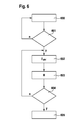
Der in Fig. 5 dargestellte Fall lässt sich in die folgenden Schritte untergliedern:
- Schritt 1: Fahrer zieht Lenkung entsprechend Gerade I weiter zu, d.h. vergrößert den Lenkwinkel. Die Gerade I weist (entsprechend den Ausführungen zu Fig. 2) den Parameter a = 0 auf.
- Schritt 2: Mit dem Erreichen des Lenkwinkels δmax hat sich ein derart großes Gegenmoment M aufgebaut, dass der Fahrer seinen Irrtum erkennt und entlang der Geraden II den Lenkwinkel jetzt richtigerweise wieder verkleinert.
- Schritt 3: An dem mit 501 bezeichneten Punkt vergrößert der Fahrer den Lenkwinkel fälschlicherweise wieder, das Moment folgt nun der mit III bezeichneten Geraden. Diese Gerade III weist dieselbe Steigung wie die Gerade I auf, hat im Unterschied zur Geraden I jedoch einen von Null verschiedenen Achsenabschnitt a.
- Schritt 4: Bei Erreichen des Punkte 502 erkennt der Fahrer erneut seinen Irrtum und verkleinert entlang der Geraden IV seinen Lenkwinkel, bis der Ziellenkwinkel δziel erreicht ist.
In diesem Modus wird das aufgeschaltete Moment, unabhängig von der momentanen Fahrsituation in geeigneter Weise weggenommen.


Der sich ergebende zeitliche Verlauf ist beispielhaft in der später näher erläuterten Fig. 4 dargestellt. Dabei berechnet sich das Moment M zum Zeitpunkt k+1 aus der rekursiven Gleichung:
Claims (13)
- Verfahren zur Stabilisierung eines Fahrzeugs in einem untersteuernden Fahrzustand, bei demein Ziellenkwinkel (δziel) ermittelt wird,bei einer Lenkbewegung des Fahrers, welche die Differenz zwischen dem aktuellen Lenkwinkel (δact_abs) und dem Ziellenkwinkel (δziel) vergrößert, ein mit zunehmender Differenz größer werdendes Unterstützungsdrehmoment (M) auf das Lenkrad aufgebracht wird,bei einer Lenkbewegung des Fahrers, welche die Differenz zwischen dem aktuellen Lenkwinkel (δact_abs) und dem Ziellenkwinkel (δziel) verringert, ein mit abnehmender Differenz kleiner werdendes Unterstützungsdrehmoment (M) auf das Lenkrad aufgebracht wird,wobei das Unterstützungsdrehmoment (M) dem Lenkrad eine Drehrichtung vorgibt undwobei bei einer Drehbewegung des Lenkrads durch den Fahrer in Richtung der vorgegebenen Drehrichtung der Lenkwinkel (δact_abs) und dem Ziellenkwinkel (δziel) angenähert wird.
- Verfahren nach Anspruch 1, dadurch gekennzeichnet, dass es sichbei dem Lenkwinkel (δact_abs) um den Radlenkwinkel handelt undbei dem Ziellenkwinkel (δziel) um den Zielradlenkwinkel handelt.
- Verfahren nach Anspruch 1, dadurch gekennzeichnet, dass der Lenkwinkel (δact_abs) und der Ziellenkwinkel (δziel) jeweils auf die Vorderräder bezogen sind.
- Verfahren nach Anspruch 1, dadurch gekennzeichnet, dass der Ziellenkwinkel (δziel) wenigstens aus der Fahrzeuggeschwindigkeit und der Giergeschwindigkeit ermittelt wird.
- Verfahren nach Anspruch 4, dadurch gekennzeichnet, dass der Ziellenkwinkel (δziel) anhand der Beziehungermittelt wird, wobei ψ ˙ die aktuelle Gierrate, v die aktuelle Geschwindigkeit, v char die charakteristische Geschwindigkeit und l der Radstand des Fahrzeugs sind.
- Verfahren nach Anspruch 1, dadurch gekennzeichnet, dass eine Aktivierung des Verfahrens dann stattfindet, wennein untersteuernder Fahrzustand des Fahrzeugs festgestellt wird undder Fahrer das Lenkrad derart dreht, dass eine Vergrößerung des Lenkwinkels stattfindet.
- Verfahren nach Anspruch 1, dadurch gekennzeichnet,dass das Unterstützungsdrehmoment (M) zum Zeitpunkt der Aktivierung des Verfahrens Null ist unddass für den Fall, dass durch die Lenkbewegung des Fahrers die Differenz zwischen dem aktuellen Lenkwinkel (δact_abs) und dem Ziellenkwinkel (δziel) vergrößert wird, das Unterstützungsdrehmoment (M) mit zunehmender Differenz zwischen dem aktuellen Lenkwinkel (δact_abs) und dem zum Zeitpunkt der Aktivierung des Verfahrens vorliegenden Lenkwinkel (δstart) anwächst.
- Verfahren nach Anspruch 7, dadurch gekennzeichnet, dass das Unterstützungsdrehmoment (M) proportional zur Differenz zwischen dem aktuellen Lenkwinkel (δact_abs) und dem zum Zeitpunkt der Aktivierung des Verfahrens vorliegenden Lenkwinkel (δstart) anwächst.
- Verfahren nach Anspruch 7, dadurch gekennzeichnet, dass für den Fall, dass beginnend mit dem Zeitpunkt der Aktivierung des Verfahrensdas im ersten Zeitintervall aufgebaute Unterstützungsdrehmoment (Mact) im zweiten Zeitintervall abhängig von der Differenz zwischen dem aktuellen Lenkwinkel (δact_abs) und dem Ziellenkwinkel (δziel) derart verringert wird, dass bei Erreichen des Ziellenkwinkels (δziel) das Unterstützungsdrehmoment (Mact) verschwindet.in einem ersten Zeitintervall durch die Lenkbewegung des Fahrers die Differenz zwischen dem aktuellen Lenkwinkel (δact_abs) und dem Ziellenkwinkel (δziel) vergrößert wird undanschließend in einem zweiten Zeitintervall durch die Lenkbewegung des Fahrers die Lenkrichtung geändert wird und die Differenz zwischen dem aktuellen Lenkwinkel (δact_abs) und dem Ziellenkwinkel (δziel) verkleinert wird,
- Verfahren nach Anspruch 9, dadurch gekennzeichnet, dass die Verringerung des Unterstützungsdrehmoments (M) im zweiten Zeitintervall derart erfolgt, dass das Unterstützungsdrehmoment (M) proportional zur Differenz zwischen dem aktuellen Lenkwinkel (δact_abs) und dem Ziellenkwinkel (δziel) abnimmt.
- Verfahren nach Anspruch 1, dadurch gekennzeichnet, dass eine Deaktivierung des Verfahrens dann stattfindet, wenn der Fahrer das Lenkrad während eines Zeitintervalls vorgegebener Länge entgegen der durch das Unterstützungsdrehmoment (M) vorgegebenen Drehrichtung dreht.
- Verfahren nach Anspruch 11, dadurch gekennzeichnet, dass bei einer Deaktivierung des Verfahrens das bis zum Zeitpunkt der Deaktivierung aufgebaute Unterstützungsmoment derart abgebaut wird, dass sowohl der zeitliche Momentenverlauf (M) als auch der zeitliche Verlauf der Momentenänderung pro Zeiteinheit ΔM(k)/Δt stetige Funktionen der Zeit (t) sind.
- Vorrichtung zur Durchführung des Verfahrens nach einem der vorhergehenden Ansprüche.
Applications Claiming Priority (2)
| Application Number | Priority Date | Filing Date | Title |
|---|---|---|---|
| DE102004029835 | 2004-06-19 | ||
| DE102004029835A DE102004029835A1 (de) | 2004-06-19 | 2004-06-19 | Verfahren und Vorrichtung zur Lenkunterstützung in Untersteuersituationen |
Publications (3)
| Publication Number | Publication Date |
|---|---|
| EP1607306A2 true EP1607306A2 (de) | 2005-12-21 |
| EP1607306A3 EP1607306A3 (de) | 2006-02-15 |
| EP1607306B1 EP1607306B1 (de) | 2007-08-29 |
Family
ID=34979479
Family Applications (1)
| Application Number | Title | Priority Date | Filing Date |
|---|---|---|---|
| EP05103271A Expired - Lifetime EP1607306B1 (de) | 2004-06-19 | 2005-04-22 | Verfahren und Vorrichtung zur Lenkunterstützung in Untersteuersituationen |
Country Status (3)
| Country | Link |
|---|---|
| EP (1) | EP1607306B1 (de) |
| KR (1) | KR101023608B1 (de) |
| DE (2) | DE102004029835A1 (de) |
Cited By (4)
| Publication number | Priority date | Publication date | Assignee | Title |
|---|---|---|---|---|
| FR2884793A1 (fr) * | 2005-04-21 | 2006-10-27 | Bosch Gmbh Robert | Procede et dispositif pour la stabilisation d'un vehicule automobile |
| WO2010070229A1 (fr) * | 2008-12-19 | 2010-06-24 | Jtekt Europe | Procédé de détermination du taux de sous-virage d'un véhicule équipé d'une direction assistée électrique, et de correction éventuelle de l'assistance de direction |
| US8457843B2 (en) | 2008-06-27 | 2013-06-04 | Robert Bosch Gmbh | Device and method for controlling an automatic steering system of a vehicle, and device and method for checking the ability to implement a predefined setpoint travel direction variable for a vehicle |
| WO2020169273A1 (de) * | 2019-02-19 | 2020-08-27 | Zf Friedrichshafen Ag | Steuervorrichtung und -verfahren sowie computer-programm-produkt |
Families Citing this family (6)
| Publication number | Priority date | Publication date | Assignee | Title |
|---|---|---|---|---|
| DE102006019732B4 (de) * | 2006-04-28 | 2019-03-14 | Bayerische Motoren Werke Aktiengesellschaft | Fahrzeug-Servolenksystem mit elektromotorischer Momentenunterstützung |
| DE102009045046A1 (de) * | 2009-09-28 | 2011-03-31 | Zf Lenksysteme Gmbh | Verfahren zum Betrieb eines elektronischen Servolenksystems eines Kraftfahrzeugs |
| DE102014005011A1 (de) * | 2014-04-05 | 2015-10-08 | Audi Ag | Verfahren und Vorrichtung zur Stabilisierung eines erfassten instabilen Fahrzustands eines Kraftfahrzeugs |
| DE102015219443B4 (de) | 2015-10-07 | 2019-01-31 | Bayerische Motoren Werke Aktiengesellschaft | Fahrzeug-Servolenksystem mit elektromotorischer Momentenunterstützung |
| KR102335985B1 (ko) | 2017-07-04 | 2021-12-07 | 현대자동차주식회사 | 조향각 제어 장치, 그를 포함한 차로 추종 보조 시스템 및 그 방법 |
| DE102024206953A1 (de) * | 2024-07-24 | 2026-01-29 | Volkswagen Aktiengesellschaft | Verfahren zur Führung eines Fahrzeugs mittels eines elektronischen Fahrzeugführungssystems und elektronisches Fahrzeugführungssystem zum Führen eines Fahrzeugs |
Family Cites Families (7)
| Publication number | Priority date | Publication date | Assignee | Title |
|---|---|---|---|---|
| JPH0686218B2 (ja) * | 1986-01-24 | 1994-11-02 | 日産自動車株式会社 | 操舵反力制御装置 |
| JPH05270419A (ja) * | 1992-03-27 | 1993-10-19 | Toyota Motor Corp | 車両運動制御装置 |
| DE19918597C2 (de) * | 1999-04-23 | 2001-03-08 | Deutsch Zentr Luft & Raumfahrt | Verfahren zur Reduktion der Kippgefahr von Straßenfahrzeugen |
| DE19964048A1 (de) * | 1999-06-30 | 2001-01-04 | Bosch Gmbh Robert | Verfahren und Einrichtung zum Stabilisieren eines Straßenfahrzeugs |
| JP3671829B2 (ja) * | 2000-10-16 | 2005-07-13 | 日産自動車株式会社 | 電動パワーステアリング装置 |
| GB0106924D0 (en) * | 2001-03-20 | 2001-05-09 | Lucas Industries Ltd | Oversteer steering assistance controller |
| JP3988182B2 (ja) * | 2002-03-29 | 2007-10-10 | マツダ株式会社 | 自動車の電動パワーステアリング装置 |
-
2004
- 2004-06-19 DE DE102004029835A patent/DE102004029835A1/de not_active Withdrawn
-
2005
- 2005-04-22 EP EP05103271A patent/EP1607306B1/de not_active Expired - Lifetime
- 2005-04-22 DE DE502005001352T patent/DE502005001352D1/de not_active Expired - Lifetime
- 2005-06-17 KR KR1020050052250A patent/KR101023608B1/ko not_active Expired - Fee Related
Cited By (7)
| Publication number | Priority date | Publication date | Assignee | Title |
|---|---|---|---|---|
| FR2884793A1 (fr) * | 2005-04-21 | 2006-10-27 | Bosch Gmbh Robert | Procede et dispositif pour la stabilisation d'un vehicule automobile |
| US8457843B2 (en) | 2008-06-27 | 2013-06-04 | Robert Bosch Gmbh | Device and method for controlling an automatic steering system of a vehicle, and device and method for checking the ability to implement a predefined setpoint travel direction variable for a vehicle |
| EP2384953B1 (de) * | 2008-06-27 | 2014-01-15 | Robert Bosch GmbH | Vorrichtung und Verfahren zum Überprüfen einer Ausführbarkeit einer vorgegebenen Soll-Fahrtrichtungsgröße für ein Fahrzeug |
| WO2010070229A1 (fr) * | 2008-12-19 | 2010-06-24 | Jtekt Europe | Procédé de détermination du taux de sous-virage d'un véhicule équipé d'une direction assistée électrique, et de correction éventuelle de l'assistance de direction |
| FR2940233A1 (fr) * | 2008-12-19 | 2010-06-25 | Jtekt Europe Sas | Procede de determination du taux de sous-virage d'un vehicule equipe d'une direction assistee electrique, et de correction eventuelle de l'assistance de direction |
| US8874320B2 (en) | 2008-12-19 | 2014-10-28 | Jtekt Europe | Method for determining the understeering ratio of a vehicle provided with electric power steering and for optionally correcting the power steering |
| WO2020169273A1 (de) * | 2019-02-19 | 2020-08-27 | Zf Friedrichshafen Ag | Steuervorrichtung und -verfahren sowie computer-programm-produkt |
Also Published As
| Publication number | Publication date |
|---|---|
| KR101023608B1 (ko) | 2011-03-21 |
| DE502005001352D1 (de) | 2007-10-11 |
| EP1607306B1 (de) | 2007-08-29 |
| DE102004029835A1 (de) | 2005-12-29 |
| EP1607306A3 (de) | 2006-02-15 |
| KR20060049621A (ko) | 2006-05-19 |
Similar Documents
| Publication | Publication Date | Title |
|---|---|---|
| DE10354662B4 (de) | Verfahren und Vorrichtung zum Unterstützen des Fahrers eines Kraftfahrzeugs in fahrdynamischen Grenzsituationen | |
| EP3496995B1 (de) | Regelung eines steer-by-wire-lenksystems | |
| EP2013069B1 (de) | Verfahren und vorrichtung zum ermitteln eines optimalen lenkwinkels in untersteuersituationen eines fahrzeugs | |
| EP1807300B1 (de) | Verfahren und vorrichtung zum unterstützen eines fahrzeugbedieners beim stabilisieren eines fahrzeugs | |
| EP2155534B1 (de) | Fahrerassistenzvorrichtung und verfahren für dessen steuerung | |
| DE102011080789B4 (de) | Verfahren und System zur Regelung der Fahrstabilität | |
| DE112017004674B4 (de) | Fahrzeugsteuerverfahren und elektrisches servolenksystem | |
| DE102007000326B4 (de) | Lenksteuergerät für ein Fahrzeug | |
| EP0904225B1 (de) | Verfahren und vorrichtung zum betrieb eines lenksystems für ein kraftfahrzeug | |
| EP3331749B1 (de) | Verfahren zum lenken eines fahrzeuges | |
| EP3738860B1 (de) | Verfahren und lenkungssteuergerät zum ermitteln einer stellgrösse für das einstellen eines servolenkmoments bei einem fahrzeuglenksystem | |
| EP1843924A1 (de) | Verfahren und vorrichtung zur vermeidung und/oder minderung der folgen von kollisionen beim ausweichen vor hindernissen | |
| DE102013009399A1 (de) | Verfahren zur Erkennung einer kritischen Fahrsituation eines Fahrzeugs | |
| WO2021058405A1 (de) | Verfahren und vorrichtung zur simultanen lateralen fahrzeugführung durch fahrer und assistenzsystem bei elektrischen lenkaktoren | |
| EP1607306B1 (de) | Verfahren und Vorrichtung zur Lenkunterstützung in Untersteuersituationen | |
| EP1536957B1 (de) | Verfahren zur steuerung und regelung von digital oder analog einstellbaren stossdämpfern | |
| DE102005018519B4 (de) | Verfahren zur Fahrdynamik-Regelung von Kraftfahrzeugen | |
| DE102016214564A1 (de) | Verfahren und Steuersystem zur Fahrdynamikregelung eines Fahrzeugs und Fahrzeug | |
| WO2010089061A1 (de) | Verfahren zur steuerung eines spurhalteassistenten und spurhalteassistent | |
| EP4013651B1 (de) | Verfahren zum steuern eines fahrzeuges bei einer bremsung mit seitenweise unterschiedlich wirkenden bremskräften, steuersystem und fahrzeug | |
| DE102005012548A1 (de) | Verfahren und Lenkvorrichtung zum Erhöhen der Fahrstabilität eines Fahrzeugs während der Fahrt durch eine Kurve | |
| WO2023094046A1 (de) | Verfahren zum steuern eines lenksystems für ein kraftfahrzeug und lenksystem für ein kraftfahrzeug zum durchführen des verfahrens | |
| DE102008001179A1 (de) | Verfahren zum Betrieb eines Lenksystems in einem Fahrzeug | |
| DE102007002362B4 (de) | Verfahren zur Einstellung eines Lenkwinkels an der Vorderachse eines untersteuernden Kraftfahrzeuges mit Hilfe einer Zusatzlenkung sowie aktives Lenksystem | |
| EP4093651B1 (de) | Überlenkbare fahrerassistenzfunktion mit verbessertem lenkgefühl |
Legal Events
| Date | Code | Title | Description |
|---|---|---|---|
| PUAI | Public reference made under article 153(3) epc to a published international application that has entered the european phase |
Free format text: ORIGINAL CODE: 0009012 |
|
| AK | Designated contracting states |
Kind code of ref document: A2 Designated state(s): AT BE BG CH CY CZ DE DK EE ES FI FR GB GR HU IE IS IT LI LT LU MC NL PL PT RO SE SI SK TR |
|
| AX | Request for extension of the european patent |
Extension state: AL BA HR LV MK YU |
|
| PUAL | Search report despatched |
Free format text: ORIGINAL CODE: 0009013 |
|
| AK | Designated contracting states |
Kind code of ref document: A3 Designated state(s): AT BE BG CH CY CZ DE DK EE ES FI FR GB GR HU IE IS IT LI LT LU MC NL PL PT RO SE SI SK TR |
|
| AX | Request for extension of the european patent |
Extension state: AL BA HR LV MK YU |
|
| 17P | Request for examination filed |
Effective date: 20060816 |
|
| AKX | Designation fees paid |
Designated state(s): DE FR IT |
|
| GRAC | Information related to communication of intention to grant a patent modified |
Free format text: ORIGINAL CODE: EPIDOSCIGR1 |
|
| GRAP | Despatch of communication of intention to grant a patent |
Free format text: ORIGINAL CODE: EPIDOSNIGR1 |
|
| GRAS | Grant fee paid |
Free format text: ORIGINAL CODE: EPIDOSNIGR3 |
|
| GRAA | (expected) grant |
Free format text: ORIGINAL CODE: 0009210 |
|
| AK | Designated contracting states |
Kind code of ref document: B1 Designated state(s): DE FR IT |
|
| REF | Corresponds to: |
Ref document number: 502005001352 Country of ref document: DE Date of ref document: 20071011 Kind code of ref document: P |
|
| ET | Fr: translation filed | ||
| PLBE | No opposition filed within time limit |
Free format text: ORIGINAL CODE: 0009261 |
|
| STAA | Information on the status of an ep patent application or granted ep patent |
Free format text: STATUS: NO OPPOSITION FILED WITHIN TIME LIMIT |
|
| 26N | No opposition filed |
Effective date: 20080530 |
|
| PGFP | Annual fee paid to national office [announced via postgrant information from national office to epo] |
Ref country code: FR Payment date: 20140416 Year of fee payment: 10 |
|
| REG | Reference to a national code |
Ref country code: FR Ref legal event code: ST Effective date: 20151231 |
|
| PG25 | Lapsed in a contracting state [announced via postgrant information from national office to epo] |
Ref country code: FR Free format text: LAPSE BECAUSE OF NON-PAYMENT OF DUE FEES Effective date: 20150430 |
|
| PGFP | Annual fee paid to national office [announced via postgrant information from national office to epo] |
Ref country code: IT Payment date: 20200423 Year of fee payment: 16 |
|
| PGFP | Annual fee paid to national office [announced via postgrant information from national office to epo] |
Ref country code: DE Payment date: 20210624 Year of fee payment: 17 |
|
| REG | Reference to a national code |
Ref country code: DE Ref legal event code: R119 Ref document number: 502005001352 Country of ref document: DE |
|
| PG25 | Lapsed in a contracting state [announced via postgrant information from national office to epo] |
Ref country code: DE Free format text: LAPSE BECAUSE OF NON-PAYMENT OF DUE FEES Effective date: 20221103 |
|
| PG25 | Lapsed in a contracting state [announced via postgrant information from national office to epo] |
Ref country code: IT Free format text: LAPSE BECAUSE OF NON-PAYMENT OF DUE FEES Effective date: 20200422 |
|
| PG25 | Lapsed in a contracting state [announced via postgrant information from national office to epo] |
Ref country code: IT Free format text: LAPSE BECAUSE OF NON-PAYMENT OF DUE FEES Effective date: 20210422 |