EP1607123A1 - Anhängerkupplung für ein Spielfahrzeug - Google Patents
Anhängerkupplung für ein Spielfahrzeug Download PDFInfo
- Publication number
- EP1607123A1 EP1607123A1 EP05010480A EP05010480A EP1607123A1 EP 1607123 A1 EP1607123 A1 EP 1607123A1 EP 05010480 A EP05010480 A EP 05010480A EP 05010480 A EP05010480 A EP 05010480A EP 1607123 A1 EP1607123 A1 EP 1607123A1
- Authority
- EP
- European Patent Office
- Prior art keywords
- toy vehicle
- trailer
- connecting piece
- device adapter
- joint
- Prior art date
- Legal status (The legal status is an assumption and is not a legal conclusion. Google has not performed a legal analysis and makes no representation as to the accuracy of the status listed.)
- Granted
Links
Images


Classifications
-
- A—HUMAN NECESSITIES
- A63—SPORTS; GAMES; AMUSEMENTS
- A63H—TOYS, e.g. TOPS, DOLLS, HOOPS OR BUILDING BLOCKS
- A63H17/00—Toy vehicles, e.g. with self-drive; ; Cranes, winches or the like; Accessories therefor
- A63H17/26—Details; Accessories
- A63H17/264—Coupling mechanisms
-
- A—HUMAN NECESSITIES
- A63—SPORTS; GAMES; AMUSEMENTS
- A63H—TOYS, e.g. TOPS, DOLLS, HOOPS OR BUILDING BLOCKS
- A63H17/00—Toy vehicles, e.g. with self-drive; ; Cranes, winches or the like; Accessories therefor
- A63H17/12—Toy vehicles, e.g. with self-drive; ; Cranes, winches or the like; Accessories therefor with cranes, winches or the like
Definitions
- the invention relates to a trailer hitch for a toy vehicle, in particular a toy tractor, a connector for such a trailer hitch, a toy vehicle and a toy vehicle trailer.
- Toy vehicles, in particular toy tractors, with a trailer hitch are already known.
- the trailer hitch can be turned upwards Coupling pin which, in an opening of a drawbar of a toy vehicle trailer can intervene.
- the Coupling pin formed circular cylindrical. He goes through an appropriate circular cylindrical opening of the drawbar of the toy vehicle trailer.
- the Drawbar can then be around the vertical axis formed by the coupling pin rotate.
- the object of the invention is to improve a trailer hitch for a toy vehicle.
- the trailer hitch comprises a device adapter, a joint receptacle and has a fixed recording.
- the trailer hitch is designed such that it with a fitting provided on a toy vehicle trailer can, can interact.
- the connector for the trailer hitch includes a hinge part and a receiving part.
- the joint part can with the joint recording cooperate, and the receiving part can interact with the capture.
- the device adapter of the trailer hitch can also with a connecting piece, the only one hinge part, but not one Receiving part has.
- the drawbar of the toy vehicle trailer can in turn be articulated and / or movable in other ways be connected to the toy vehicle trailer. Furthermore, the drawbar be firmly connected to the toy vehicle trailer or from a part of Toy vehicle trailer be formed.
- the fixed receptacle can interact with the receiving part such that between the connector and the device adapter only a limited relative movement or no relative movement is possible.
- the joint receptacle can be a ball joint receptacle.
- the capture is preferably semi-cylindrical. In this case is a limited Movement or no movement between the fitting and the trailer hitch possible. Instead of a semi-cylindrical configuration the capture can also be chosen a design that has a similar limited relative movement allowed.
- the hinge part may be part spherical.
- the recording part may be semi-cylindrical or hemispherical, or otherwise so be formed that between the connector and the device adapter a limited relative movement or no relative movement is possible.
- the fitting may have one or more support ribs.
- the toy vehicle according to the invention is characterized by a trailer hitch according to the invention characterized.
- the toy vehicle trailer according to the invention is characterized by an inventive fitting.
- the coupling device 2 consists of a trailer coupling connected to the toy tractor 1, having a device adapter 4, and a connector 5, which is connected to the drawbar 6 of the toy trailer 3.
- the device adapter 4 has a joint receptacle 7 and a fixed receptacle 8.
- the joint receptacle 7 consists of an upper hinge tongue 9, which has a passage opening 10, and a lower hinge tongue 11, which is also a Through opening 12 has.
- the pivot tongues 9, 11 point in the vehicle longitudinal direction to the rear.
- Your through holes 10, 12 form a ball joint receptacle.
- the vehicle longitudinal direction is indicated in the drawing by x, where the positive x-direction points to the front.
- the y-direction points in a horizontal Plane to the left, the z-direction points vertically upwards.
- the fixed receptacle 8 is arranged in the direction of travel x in front of the joint receptacle 7. It is the hinge seat 7 adjacent and designed semi-cylindrical, wherein the axis of the half-cylinder in the vehicle transverse direction, ie in the y-direction, runs.
- the connecting piece 5 has a hinge part 13 and a receiving part 14.
- the Joint part 13 consists of an upper part spherical surface 15 and a lower part spherical surface 16.
- the receiving part 14 is configured semi-cylindrical. The axis of the half cylinder runs in the horizontal transverse direction, ie in the y direction.
- the connector 5 In the coupled state, which is shown in Fig. 5, are the partial spherical surfaces 15, 16 of the joint part 13 in the through holes 10, 12 of the pivot tongues 9, 11th and is the semi-cylindrical receiving part 14 in the semi-cylindrical fixed receptacle 8.
- the connector 5 is fixed in this way with the device adapter 4 connected. A relative movement between the connector 5 and the device adapter 4 is not possible.
- the connector 5 has opposite the device adapter 4 no degree of freedom (movement degree of freedom) on.
- a rotary motion around the x-axis, the y-axis and the z-axis is represented by the semi-cylindrical Receiving part 14, which is located in the semi-cylindrical fixed receptacle 8 prevents.
- the toy truck trailer 17 shown in Fig. 2 comprises a drawbar 18, at the front end there is a fitting which consists of a ball joint forming ball 19 consists.
- the ball 19 is dimensioned so that in the same way as the part-spherical surfaces 15, 16 of the joint part 13 of the fitting 5 in the through holes 10, 12 of the pivot tongues 9, 11 of the device adapter 4 can come to rest.
- the connector of the toy truck trailer 17 has no receiving part, but only one Joint consists part, namely from the ball joint forming a ball 19, this has Connector in the device adapter 4 movement possibilities around all Axes, so both the x-axis pointing in the vehicle longitudinal direction to the in horizontal vehicle transverse direction pointing y-axis and around in vertical Directional z-axis.
- the toy truck trailer 17 has accordingly three degrees of freedom.
- the ball 19 with a hemispherical receiving part (not shown in the drawing), which is connected to the ball 19 and the Ball 19 is adjacent in the x-direction.
- This hemispherical receiving part is located in the middle region of the semi-cylindrical retainer 8.
- the hemispherical receiving part is a rotation of the drawbar 18 connected Connector prevents the y-axis. A rotation around the x-axis and around the z-axis, however, are still possible. In this case, the Pendant two degrees of freedom.
- the hinge tongues 9, 11 point in their opposite areas Ein Industriesschrägen 20, 21, through which the elastic expansion of the pivot tongues 9, 11 during insertion of the connector 5 and the ball 19 is facilitated.
- an upper support rib 22 is provided, which in the x direction protrudes and the front end 23 in the engaged state on a End plate 24 'of the device adapter 4 is present. Through the upper support rib 22nd a stop is formed when engaging.
- the connector 5 has a left support rib 24 and a right support rib 25, which extend in the x direction and at which stages 26, 27 are provided are in the engaged state on the end plate 24 'of the device adapter 4 abut.
- connection between the connector 5 and the device adapter 4 can be solved by the fact that these two parts pulled apart become. The manufacture and the release of the connection thus takes place Plug in and pull apart.
- the device adapter 4 is suitable both for connection to a connector 5, which has a hinge part 13 and a receiving part 14, as well as for connection with a ball joint consisting of a ball 19. Accordingly For example, you can use different fittings in conjunction with a single device adapter can be used, so that the variety of game options increases becomes.
- the invention makes it possible to use a toy vehicle the same device adapter to connect to different toy vehicle trailers, which are movable in different ways in relation to the toy vehicle: by a ball joint having three degrees of freedom, or by a fitting with two, one or no degree of freedom. For all movement possibilities one and the same device adapter suffices.
Landscapes
- Toys (AREA)
Abstract
Description
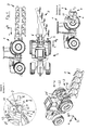
- Fig. 1
- einen Spielzeugmodell-Traktor und einen landwirtschaftlichen Spielfahrzeug-Anhänger in verschiedenen Ansichten, teilweise im Schnitt,
- Fig. 2
- den Spielfahrzeug-Traktor gemäß Fig. 1 und einen Spielfahrzeug-Lastwagenanhänger in verschiedenen Ansichten, teilweise im Schnitt,
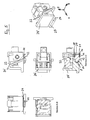
- Fig. 3
- den Geräteadapter für den Spielfahrzeug-Traktor nach Fig. 1 und 2 in verschiedenen Ansichten, teilweise im Schnitt,
- Fig. 4
- das Anschlußstück des landwirtschaftlichen Spielfahrzeug-Anhängers gemäß Fig. 1 in verschiedenen Ansichten, teilweise im Schnitt,
- Fig. 5
- den Geräteadapter gemäß Fig. 3 und das Anschlußstück gemäß Fig. 4 im eingekuppelten Zustand in verschiedenen Ansichten, teilweise im Schnitt und
- Fig. 6 und 7
- den Geräteadapter des Spielfahrzeug-Traktors gemäß Fig.1 bis 5 und einen Teil des Spielfahrzeug-Lastwagenanhängers gemäß Fig. 2 im eingekuppelten Zustand in verschiedenen Ansichten, teilweise im Schnitt.
Claims (10)
- Anhängerkupplung für ein Spielfahrzeug (1) mit einem Geräteadapter (4), der eine Gelenkaufnahme (7) und eine Festaufnahme (8) aufweist.
- Anhängerkupplung nach Anspruch 1, dadurch gekennzeichnet, daß die Geleknaufnahme (7) eine Kugelgelenkaufnahme ist.
- Anhängerkupplung nach Anspruch 1 oder 2, dadurch gekennzeichnet, daß die Festaufnahme (8) halbzylinderförmig ist.
- Spielfahrzeug, gekennzeichnet durch eine Anhängerkupplung nach einem der Ansprüche 1 bis 3.
- Anschlußstück (5) für eine Anhängerkupplung nach einem der Ansprüche 1 bis 3 mit einem Gelenkteil (13) und einem Aufnahmeteil (14).
- Anschlußstück nach Anspruch 5, dadurch gekennzeichnet, daß der Gelenkteil (13) teilkugelförmig ist.
- Anschlußstück nach Anspruch 5 oder 6, dadurch gekennzeichnet, daß der Aufnahmeteil (14) halbzylinderförmig ist.
- Anschlußstück nach einem der Ansprüche 5 bis 7, dadurch gekennzeichnet, daß der Aufnahmeteil halbkugelförmig ist.
- Anschlußstück nach einem der Ansprüche 5 bis 8, gekennzeichnet durch eine oder mehrere Abstützrippen (22, 24, 25).
- Spielfahrzeug-Anhänger, gekennzeichnet durch ein Anschlußstück nach einem der Ansprüche 5 bis 9.
Applications Claiming Priority (2)
| Application Number | Priority Date | Filing Date | Title |
|---|---|---|---|
| DE202004009400U DE202004009400U1 (de) | 2004-06-14 | 2004-06-14 | Anhängerkupplung für ein Spielfahrzeug |
| DE202004009400U | 2004-06-14 |
Publications (2)
| Publication Number | Publication Date |
|---|---|
| EP1607123A1 true EP1607123A1 (de) | 2005-12-21 |
| EP1607123B1 EP1607123B1 (de) | 2010-06-09 |
Family
ID=34936502
Family Applications (1)
| Application Number | Title | Priority Date | Filing Date |
|---|---|---|---|
| EP05010480A Not-in-force EP1607123B1 (de) | 2004-06-14 | 2005-05-13 | Anhängerkupplung für ein Spielfahrzeug |
Country Status (3)
| Country | Link |
|---|---|
| EP (1) | EP1607123B1 (de) |
| AT (1) | ATE470491T1 (de) |
| DE (2) | DE202004009400U1 (de) |
Cited By (1)
| Publication number | Priority date | Publication date | Assignee | Title |
|---|---|---|---|---|
| EP1902765A1 (de) * | 2006-09-23 | 2008-03-26 | Bruder Spielwaren GmbH + Co. KG | Kupplungsanordnung für Spielzeug-Fahrzeuge |
Families Citing this family (1)
| Publication number | Priority date | Publication date | Assignee | Title |
|---|---|---|---|---|
| DE102022108992A1 (de) | 2022-04-13 | 2023-10-19 | Dynamiko Holz & Spiel GmbH | Anhängevorrichtung für ein Spielfahrzeug |
Citations (3)
| Publication number | Priority date | Publication date | Assignee | Title |
|---|---|---|---|---|
| US4940442A (en) * | 1987-06-23 | 1990-07-10 | Takara Co., Ltd. | Connectable self-powdered mobile toy |
| EP0856342A1 (de) * | 1997-01-29 | 1998-08-05 | Bruder Spielwaren GmbH + Co. KG | Anhänger-Kupplung für Spiel-Fahrzeuge, insbesondere Traktorkupplung |
| US6672936B1 (en) * | 2002-10-21 | 2004-01-06 | The Little Tikes Company | Toy truck |
-
2004
- 2004-06-14 DE DE202004009400U patent/DE202004009400U1/de not_active Expired - Lifetime
-
2005
- 2005-05-13 AT AT05010480T patent/ATE470491T1/de active
- 2005-05-13 DE DE502005009710T patent/DE502005009710D1/de active Active
- 2005-05-13 EP EP05010480A patent/EP1607123B1/de not_active Not-in-force
Patent Citations (3)
| Publication number | Priority date | Publication date | Assignee | Title |
|---|---|---|---|---|
| US4940442A (en) * | 1987-06-23 | 1990-07-10 | Takara Co., Ltd. | Connectable self-powdered mobile toy |
| EP0856342A1 (de) * | 1997-01-29 | 1998-08-05 | Bruder Spielwaren GmbH + Co. KG | Anhänger-Kupplung für Spiel-Fahrzeuge, insbesondere Traktorkupplung |
| US6672936B1 (en) * | 2002-10-21 | 2004-01-06 | The Little Tikes Company | Toy truck |
Cited By (1)
| Publication number | Priority date | Publication date | Assignee | Title |
|---|---|---|---|---|
| EP1902765A1 (de) * | 2006-09-23 | 2008-03-26 | Bruder Spielwaren GmbH + Co. KG | Kupplungsanordnung für Spielzeug-Fahrzeuge |
Also Published As
| Publication number | Publication date |
|---|---|
| ATE470491T1 (de) | 2010-06-15 |
| DE202004009400U1 (de) | 2005-10-20 |
| EP1607123B1 (de) | 2010-06-09 |
| DE502005009710D1 (de) | 2010-07-22 |
Similar Documents
| Publication | Publication Date | Title |
|---|---|---|
| DE102006020069A1 (de) | Kupplungssystem zum Verbinden von Versorgungsleitungen | |
| DE10243045B4 (de) | Anhängerkupplung | |
| EP0726176A1 (de) | Zuggabel | |
| AT413026B (de) | Zwangslenkungsmodul | |
| EP1710100B1 (de) | Schwerlastkupplung | |
| EP1607123B1 (de) | Anhängerkupplung für ein Spielfahrzeug | |
| EP1320482B1 (de) | Sattelkupplung | |
| DE10023641B4 (de) | Anhängerkupplung | |
| DE2856612A1 (de) | Fahrzeugaussenspiegel | |
| DE102006020921B4 (de) | Kupplung für Transportanhänger | |
| DE102004044912A1 (de) | Anhängekupplung mit Kugelgelenk | |
| DE3806260A1 (de) | In verbindung mit eisenbahn-drehgestellen zu verwendende kupplungsvorrichtung nach art einer dynamischen kupplung | |
| DE102006023179A1 (de) | Anbauvorrichtung für eine Landmaschine | |
| DE102019105239A1 (de) | Kopplungseinrichtung eines Routenzugs | |
| DE2712960C3 (de) | Kupplungsvorrichtung für landwirtschaftliche Anhängegeräte | |
| DE10257807B4 (de) | Sattelkupplung | |
| WO2002036370A1 (de) | Aufliegerkupplung | |
| DE2265144A1 (de) | Anhaengekupplung | |
| DE102022108992A1 (de) | Anhängevorrichtung für ein Spielfahrzeug | |
| DE3236390A1 (de) | Gelenkvorrichtung fuer streurampen | |
| DE4413019C2 (de) | Fahrzeug mit einem spurtreuen Fahrwerk und einer Anhängevorrichtung | |
| AT391662B (de) | Zwischenkupplung zum verbinden von fahrzeugen, insbesondere von strassenfahrzeugen | |
| DE19515414A1 (de) | Anhängerdeichsel | |
| EP0356849A2 (de) | Zentralachsanhänger | |
| DE102010048996A1 (de) | Vorrichtung zum automatischen Einhängen und Verriegeln einer Anhängerkupplung zwischen einem ziehenden und einem gezogenen Straßenfahrzeug |
Legal Events
| Date | Code | Title | Description |
|---|---|---|---|
| PUAI | Public reference made under article 153(3) epc to a published international application that has entered the european phase |
Free format text: ORIGINAL CODE: 0009012 |
|
| AK | Designated contracting states |
Kind code of ref document: A1 Designated state(s): AT BE BG CH CY CZ DE DK EE ES FI FR GB GR HU IE IS IT LI LT LU MC NL PL PT RO SE SI SK TR |
|
| AX | Request for extension of the european patent |
Extension state: AL BA HR LV MK YU |
|
| 17P | Request for examination filed |
Effective date: 20060131 |
|
| AKX | Designation fees paid |
Designated state(s): AT BE BG CH CY CZ DE DK EE ES FI FR GB GR HU IE IS IT LI LT LU MC NL PL PT RO SE SI SK TR |
|
| 17Q | First examination report despatched |
Effective date: 20080617 |
|
| GRAP | Despatch of communication of intention to grant a patent |
Free format text: ORIGINAL CODE: EPIDOSNIGR1 |
|
| GRAS | Grant fee paid |
Free format text: ORIGINAL CODE: EPIDOSNIGR3 |
|
| GRAA | (expected) grant |
Free format text: ORIGINAL CODE: 0009210 |
|
| AK | Designated contracting states |
Kind code of ref document: B1 Designated state(s): AT BE BG CH CY CZ DE DK EE ES FI FR GB GR HU IE IS IT LI LT LU MC NL PL PT RO SE SI SK TR |
|
| REG | Reference to a national code |
Ref country code: CH Ref legal event code: EP |
|
| REG | Reference to a national code |
Ref country code: IE Ref legal event code: FG4D Free format text: LANGUAGE OF EP DOCUMENT: GERMAN |
|
| REF | Corresponds to: |
Ref document number: 502005009710 Country of ref document: DE Date of ref document: 20100722 Kind code of ref document: P |
|
| REG | Reference to a national code |
Ref country code: NL Ref legal event code: T3 |
|
| PG25 | Lapsed in a contracting state [announced via postgrant information from national office to epo] |
Ref country code: LT Free format text: LAPSE BECAUSE OF FAILURE TO SUBMIT A TRANSLATION OF THE DESCRIPTION OR TO PAY THE FEE WITHIN THE PRESCRIBED TIME-LIMIT Effective date: 20100609 Ref country code: SE Free format text: LAPSE BECAUSE OF FAILURE TO SUBMIT A TRANSLATION OF THE DESCRIPTION OR TO PAY THE FEE WITHIN THE PRESCRIBED TIME-LIMIT Effective date: 20100609 |
|
| LTIE | Lt: invalidation of european patent or patent extension |
Effective date: 20100609 |
|
| PG25 | Lapsed in a contracting state [announced via postgrant information from national office to epo] |
Ref country code: FI Free format text: LAPSE BECAUSE OF FAILURE TO SUBMIT A TRANSLATION OF THE DESCRIPTION OR TO PAY THE FEE WITHIN THE PRESCRIBED TIME-LIMIT Effective date: 20100609 Ref country code: SI Free format text: LAPSE BECAUSE OF FAILURE TO SUBMIT A TRANSLATION OF THE DESCRIPTION OR TO PAY THE FEE WITHIN THE PRESCRIBED TIME-LIMIT Effective date: 20100609 |
|
| PG25 | Lapsed in a contracting state [announced via postgrant information from national office to epo] |
Ref country code: CY Free format text: LAPSE BECAUSE OF FAILURE TO SUBMIT A TRANSLATION OF THE DESCRIPTION OR TO PAY THE FEE WITHIN THE PRESCRIBED TIME-LIMIT Effective date: 20100609 Ref country code: PL Free format text: LAPSE BECAUSE OF FAILURE TO SUBMIT A TRANSLATION OF THE DESCRIPTION OR TO PAY THE FEE WITHIN THE PRESCRIBED TIME-LIMIT Effective date: 20100609 Ref country code: GR Free format text: LAPSE BECAUSE OF FAILURE TO SUBMIT A TRANSLATION OF THE DESCRIPTION OR TO PAY THE FEE WITHIN THE PRESCRIBED TIME-LIMIT Effective date: 20100910 |
|
| REG | Reference to a national code |
Ref country code: IE Ref legal event code: FD4D |
|
| PG25 | Lapsed in a contracting state [announced via postgrant information from national office to epo] |
Ref country code: IE Free format text: LAPSE BECAUSE OF FAILURE TO SUBMIT A TRANSLATION OF THE DESCRIPTION OR TO PAY THE FEE WITHIN THE PRESCRIBED TIME-LIMIT Effective date: 20100609 Ref country code: EE Free format text: LAPSE BECAUSE OF FAILURE TO SUBMIT A TRANSLATION OF THE DESCRIPTION OR TO PAY THE FEE WITHIN THE PRESCRIBED TIME-LIMIT Effective date: 20100609 |
|
| PG25 | Lapsed in a contracting state [announced via postgrant information from national office to epo] |
Ref country code: RO Free format text: LAPSE BECAUSE OF FAILURE TO SUBMIT A TRANSLATION OF THE DESCRIPTION OR TO PAY THE FEE WITHIN THE PRESCRIBED TIME-LIMIT Effective date: 20100609 Ref country code: IS Free format text: LAPSE BECAUSE OF FAILURE TO SUBMIT A TRANSLATION OF THE DESCRIPTION OR TO PAY THE FEE WITHIN THE PRESCRIBED TIME-LIMIT Effective date: 20101009 Ref country code: SK Free format text: LAPSE BECAUSE OF FAILURE TO SUBMIT A TRANSLATION OF THE DESCRIPTION OR TO PAY THE FEE WITHIN THE PRESCRIBED TIME-LIMIT Effective date: 20100609 Ref country code: CZ Free format text: LAPSE BECAUSE OF FAILURE TO SUBMIT A TRANSLATION OF THE DESCRIPTION OR TO PAY THE FEE WITHIN THE PRESCRIBED TIME-LIMIT Effective date: 20100609 Ref country code: PT Free format text: LAPSE BECAUSE OF FAILURE TO SUBMIT A TRANSLATION OF THE DESCRIPTION OR TO PAY THE FEE WITHIN THE PRESCRIBED TIME-LIMIT Effective date: 20101011 |
|
| PG25 | Lapsed in a contracting state [announced via postgrant information from national office to epo] |
Ref country code: IT Free format text: LAPSE BECAUSE OF FAILURE TO SUBMIT A TRANSLATION OF THE DESCRIPTION OR TO PAY THE FEE WITHIN THE PRESCRIBED TIME-LIMIT Effective date: 20100609 |
|
| PLBE | No opposition filed within time limit |
Free format text: ORIGINAL CODE: 0009261 |
|
| STAA | Information on the status of an ep patent application or granted ep patent |
Free format text: STATUS: NO OPPOSITION FILED WITHIN TIME LIMIT |
|
| PG25 | Lapsed in a contracting state [announced via postgrant information from national office to epo] |
Ref country code: DK Free format text: LAPSE BECAUSE OF FAILURE TO SUBMIT A TRANSLATION OF THE DESCRIPTION OR TO PAY THE FEE WITHIN THE PRESCRIBED TIME-LIMIT Effective date: 20100609 |
|
| 26N | No opposition filed |
Effective date: 20110310 |
|
| REG | Reference to a national code |
Ref country code: DE Ref legal event code: R097 Ref document number: 502005009710 Country of ref document: DE Effective date: 20110309 |
|
| PG25 | Lapsed in a contracting state [announced via postgrant information from national office to epo] |
Ref country code: MC Free format text: LAPSE BECAUSE OF NON-PAYMENT OF DUE FEES Effective date: 20110531 |
|
| REG | Reference to a national code |
Ref country code: CH Ref legal event code: PL |
|
| PG25 | Lapsed in a contracting state [announced via postgrant information from national office to epo] |
Ref country code: LI Free format text: LAPSE BECAUSE OF NON-PAYMENT OF DUE FEES Effective date: 20110531 Ref country code: CH Free format text: LAPSE BECAUSE OF NON-PAYMENT OF DUE FEES Effective date: 20110531 |
|
| REG | Reference to a national code |
Ref country code: AT Ref legal event code: MM01 Ref document number: 470491 Country of ref document: AT Kind code of ref document: T Effective date: 20110513 |
|
| PG25 | Lapsed in a contracting state [announced via postgrant information from national office to epo] |
Ref country code: AT Free format text: LAPSE BECAUSE OF NON-PAYMENT OF DUE FEES Effective date: 20110513 |
|
| PG25 | Lapsed in a contracting state [announced via postgrant information from national office to epo] |
Ref country code: LU Free format text: LAPSE BECAUSE OF NON-PAYMENT OF DUE FEES Effective date: 20110513 |
|
| PG25 | Lapsed in a contracting state [announced via postgrant information from national office to epo] |
Ref country code: BG Free format text: LAPSE BECAUSE OF FAILURE TO SUBMIT A TRANSLATION OF THE DESCRIPTION OR TO PAY THE FEE WITHIN THE PRESCRIBED TIME-LIMIT Effective date: 20100909 Ref country code: TR Free format text: LAPSE BECAUSE OF FAILURE TO SUBMIT A TRANSLATION OF THE DESCRIPTION OR TO PAY THE FEE WITHIN THE PRESCRIBED TIME-LIMIT Effective date: 20100609 |
|
| PG25 | Lapsed in a contracting state [announced via postgrant information from national office to epo] |
Ref country code: ES Free format text: LAPSE BECAUSE OF FAILURE TO SUBMIT A TRANSLATION OF THE DESCRIPTION OR TO PAY THE FEE WITHIN THE PRESCRIBED TIME-LIMIT Effective date: 20100920 Ref country code: HU Free format text: LAPSE BECAUSE OF FAILURE TO SUBMIT A TRANSLATION OF THE DESCRIPTION OR TO PAY THE FEE WITHIN THE PRESCRIBED TIME-LIMIT Effective date: 20100609 |
|
| REG | Reference to a national code |
Ref country code: FR Ref legal event code: PLFP Year of fee payment: 11 |
|
| PGFP | Annual fee paid to national office [announced via postgrant information from national office to epo] |
Ref country code: DE Payment date: 20150529 Year of fee payment: 11 Ref country code: GB Payment date: 20150518 Year of fee payment: 11 |
|
| PGFP | Annual fee paid to national office [announced via postgrant information from national office to epo] |
Ref country code: NL Payment date: 20150516 Year of fee payment: 11 Ref country code: FR Payment date: 20150518 Year of fee payment: 11 |
|
| PGFP | Annual fee paid to national office [announced via postgrant information from national office to epo] |
Ref country code: BE Payment date: 20150430 Year of fee payment: 11 |
|
| PG25 | Lapsed in a contracting state [announced via postgrant information from national office to epo] |
Ref country code: BE Free format text: LAPSE BECAUSE OF NON-PAYMENT OF DUE FEES Effective date: 20160531 |
|
| REG | Reference to a national code |
Ref country code: DE Ref legal event code: R119 Ref document number: 502005009710 Country of ref document: DE |
|
| REG | Reference to a national code |
Ref country code: NL Ref legal event code: MM Effective date: 20160601 |
|
| GBPC | Gb: european patent ceased through non-payment of renewal fee |
Effective date: 20160513 |
|
| PG25 | Lapsed in a contracting state [announced via postgrant information from national office to epo] |
Ref country code: NL Free format text: LAPSE BECAUSE OF NON-PAYMENT OF DUE FEES Effective date: 20160601 |
|
| REG | Reference to a national code |
Ref country code: FR Ref legal event code: ST Effective date: 20170131 |
|
| PG25 | Lapsed in a contracting state [announced via postgrant information from national office to epo] |
Ref country code: DE Free format text: LAPSE BECAUSE OF NON-PAYMENT OF DUE FEES Effective date: 20161201 Ref country code: FR Free format text: LAPSE BECAUSE OF NON-PAYMENT OF DUE FEES Effective date: 20160531 |
|
| PG25 | Lapsed in a contracting state [announced via postgrant information from national office to epo] |
Ref country code: GB Free format text: LAPSE BECAUSE OF NON-PAYMENT OF DUE FEES Effective date: 20160513 |