EP1605740A2 - Haltevorrichtung zur Festlegung eines Montagewinkels - Google Patents
Haltevorrichtung zur Festlegung eines Montagewinkels Download PDFInfo
- Publication number
- EP1605740A2 EP1605740A2 EP05004345A EP05004345A EP1605740A2 EP 1605740 A2 EP1605740 A2 EP 1605740A2 EP 05004345 A EP05004345 A EP 05004345A EP 05004345 A EP05004345 A EP 05004345A EP 1605740 A2 EP1605740 A2 EP 1605740A2
- Authority
- EP
- European Patent Office
- Prior art keywords
- holding device
- mounting bracket
- spring element
- leg
- housing wall
- Prior art date
- Legal status (The legal status is an assumption and is not a legal conclusion. Google has not performed a legal analysis and makes no representation as to the accuracy of the status listed.)
- Granted
Links
Images
Classifications
-
- G—PHYSICS
- G06—COMPUTING OR CALCULATING; COUNTING
- G06F—ELECTRIC DIGITAL DATA PROCESSING
- G06F1/00—Details not covered by groups G06F3/00 - G06F13/00 and G06F21/00
- G06F1/16—Constructional details or arrangements
- G06F1/18—Packaging or power distribution
- G06F1/183—Internal mounting support structures, e.g. for supporting printed circuit boards
- G06F1/185—Mounting of expansion boards
- G06F1/186—Securing of expansion boards in correspondence to slots provided at the computer enclosure
-
- H—ELECTRICITY
- H05—ELECTRIC TECHNIQUES NOT OTHERWISE PROVIDED FOR
- H05K—PRINTED CIRCUITS; CASINGS OR CONSTRUCTIONAL DETAILS OF ELECTRIC APPARATUS; MANUFACTURE OF ASSEMBLAGES OF ELECTRICAL COMPONENTS
- H05K7/00—Constructional details common to different types of electric apparatus
- H05K7/14—Mounting supporting structure in casing or on frame or rack
- H05K7/1401—Mounting supporting structure in casing or on frame or rack comprising clamping or extracting means
- H05K7/1402—Mounting supporting structure in casing or on frame or rack comprising clamping or extracting means for securing or extracting printed circuit boards
- H05K7/1405—Mounting supporting structure in casing or on frame or rack comprising clamping or extracting means for securing or extracting printed circuit boards by clips or resilient members, e.g. hooks
Definitions
- the invention relates to a holding device for fixing a mounting bracket on a housing wall of a data processing device, wherein for each mounting bracket a clamping device is provided, which the mounting bracket on the Determines the housing wall by clamping.
- Standard flat assemblies especially those in computer technology Inserted cards are usually with Help for mounting brackets on appropriately designed slots assembled.
- each of these mounting angles is at least a connector attached to the connection of the Plug-in card to external connections manufactures.
- the housing wall Therefore, each slot-like at the bays Recesses on, covered by the respective mounting bracket become.
- On the mounting bracket is also a right angle provided retaining flange provided, which corresponds to a corresponding angled support surface of the housing wall hugs and there by means of a screw or clamp connection is releasably fixed.
- EP 0 886 819 B1 discloses a holding device known for the mounting angles of standard flat assemblies, at the each retaining flange an individual from a bow-shaped Spring element associated with existing clamping device is.
- the spring element of the respective clamping device is supported with the strap ends on the housing wall and off is between the retaining flange of the mounting bracket and respectively snap-in element provided on the housing wall.
- the disadvantage here is that with decreasing spring force the Holding force of the bow-shaped spring element wears off, and thus the reliability of the holding device is reduced.
- a holding device for fixing a mounting bracket on a housing wall of a data processing device proposed that for each mounting bracket a clamping device Provides which the mounting bracket on the housing wall arresting. It is there for each clamping device at least one spring element and at least one locking element provided, which in the locked state defines the spring element in a clamping position.
- the holding device is also preferably for the mounting bracket proposed by standard flat assemblies that the Mounting bracket to slots of slot-like recesses in a housing wall of a data processing device releasably secured. It is on an angled support surface the housing wall fitting, corresponding angled Holding flange of the mounting bracket, by means of a clamping device fixable.
- This clamping device shows a U-shaped trained bow-like spring element that deals with the temple ends supported on the housing, and between the retaining flange of the mounting bracket and each on the housing wall provided latching element is snapped.
- the bow-shaped spring element is U-shaped, and has a first and a second leg, the opposite are arranged from each other. Vorgneswiese are the two legs arranged parallel to each other.
- a locking element comprising an axle with which the locking element rotatable in an axle box on one leg of the bow-shaped spring element is mounted, and at least one Latch, which is arranged radially on the axis, serves for Locking the intrinsically elastic U-shaped Ironing element.
- the bolt is for example L-shaped trained so that he is in the locked state between the ends of the two legs spreads. This is the U-shaped bow-shaped spring element no longer compressible, because the bolt counteracts this direction of movement. To one opening of the bolt, the bolt is no longer at both Leg ends, and the bow-shaped U-shaped spring element can then be compressed against the spring force.
- the holding device extended by a base plate, with the first leg the U-shaped spring element frictionally and positively connected is.
- This base plate in turn has a bracket on, the mounting bracket at its angled Holding flange surrounds positively.
- Advantageously improve are characterized the fixing and holding properties of the retaining element opposite the mounting bracket.
- the second Leg of the U-shaped spring element with a detent completed.
- This latch is opposite the spring element so angled that the latch under the locking element, the is arranged on the housing wall, is insertable.
- the locking nose Preferably is the locking nose with about 90 ° degrees opposite angled the second leg. This results in a positive and non-positive connection of the retaining element with the housing wall.
- the bolt with a control To equip in the form of an elongated rod with the Bolt is connected.
- the control element can be rotated or be firmly connected to the bolt. Essentially depending on where the control with connected to the bolt. Attacks the operating element on the outer Ends of the bolt, and not on its axis of rotation, so it is sufficient, for example, the control firmly with the bolt To connect, so as to provide additional leverage for operation of the bolt. Is the control on this Position rotatably connected to the bolt, it can only to pull or push the latch to the desired position be used. A lever against the bar is not achievable then. Is the control element on the axis of rotation of the bolt, so it goes without saying be firmly and positively connected. Advantageously results thereby a leverage in the operation of the bolt.
- the clamping device preferably the U-shaped bracket element made of elastic Plastic formed.
- the rest the holding device is made of solid or less elastic Plastic formed because there are no elastic properties desired and needed.
- the Clamping device on the retaining flange on a centering mandrel, the through a U-shaped notch in the mounting bracket a hole-like Recess of the support surface of the housing immersed.
- a nose-like projecting handle element is at the the retaining flange facing away from the bow-shaped U-shaped Spring element a nose-like projecting handle element provided that the operation of the clamping device and in particular the compression of the spring element substantially facilitated.
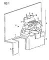
- FIG. 1 shows a section of a housing rear wall 1 a PC housing, which is in the range of two bays for Plug-in cards has an approximately rectangular recess.
- the attachment of the mounting bracket 3 or the same Cover angle takes place at the right angle bent Holding flange 4, located at one through the indentation 2 formed support surface 5 of the housing 1 hugs.
- a clamping device 6 which is a U-shaped bow-shaped spring element 7 contains, with this spring element 7 with the temple ends 8 is supported on the housing 1 and between the retaining flange 4 on the one hand and on the housing wall 1 provided latching element 9 on the other hand snap is.
- a locking element 9 is preferably one of the housing 1 torn sheet metal tab provided.
- the U-shaped bow-shaped spring element 7 is formed from a first leg 10 and a second leg 11, wherein this example of plastic in particular resilient consist of elastic plastic.
- a Locking element 12 disposed with an axis 13 in a journal bearing is rotatably mounted on one of the legs.
- the locking element 12 is preferably L-shaped and has a radially arranged locking element 15th which, in its locked state, press against each other the two legs 10 and 11 prevented by moving between the two leg ends 8 spreads.
- the distance between the two Leg ends fixed to a minimum, but if necessary also extended by a predetermined value. That's it Leg end 8 of the second leg 11 against the locking element 9 pressed so that a positive connection between Leg end 8 and locking element 9 is made.
- the clamping device further comprises a base plate 16, the at her to the inside of the data processing device directed down a sloping to the angulation of the L-shaped Mounting bracket snuggled retaining lug 17, wherein additional holding forces against the mounting bracket 3 and additional fixing properties compared to the mounting bracket 3 are feasible.
- the leg end 8 of the second leg 11 extended by an angled locking lug 18.
- this one has in the direction of the locking element directed wedge-shaped expression. This is they can be inserted under the locking element 9.
- the angling of the Latch 18 is preferably opposite 90 ° degrees the second leg 11.
- the connection is thereby closed a positive and non-positive connection advantageously extended and is opposite to a pure non-positive connection much more reliable in their lasting durability.
- the locking element 15 is characterized by a rod-shaped operating element 19 so extended that the operation of the locking element 15 and the L-shaped bolt 12 also from a remote Point can be executed and depending on the type of attachment the operating element 19 on the locking element 15 is a lever action additionally exerted on the locking element can. This is dependent on whether the connection of the control element 19 with the locking element 15 is a fixed or a rotatable connection is.
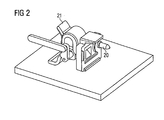
- FIG 2 shows the clamping device of Figure 1 from another Viewing direction, wherein at the retaining flange 4 facing Side of the base plate 16 of the clamping device 6 a Centering pin 20 is arranged.
- This centering mandrel 20 leads in the assembled state by a U-shaped notch in the mounting bracket and dives into a hole-like recess in the support surface 5 of the housing wall, whereby the mounting bracket is additionally fixed beyond the clamping.
- the U-shaped Recess of the mounting bracket is due in Figure 1 the perspective view not visible. additionally serves a nose-like projection as a handle member 21, the on one in particular on the second leg of the U-shaped spring element 7 is arranged.
- FIG. 1 shows the clamping device in a locked position and Figure 2 shows the clamping device in an unlocked Status.
- the locking element 15 unlocked in State not between the two leg ends 8 of the U-shaped Spring element 7 isußsp Drettit.
Landscapes
- Engineering & Computer Science (AREA)
- Computer Hardware Design (AREA)
- General Engineering & Computer Science (AREA)
- Theoretical Computer Science (AREA)
- Microelectronics & Electronic Packaging (AREA)
- Power Engineering (AREA)
- Human Computer Interaction (AREA)
- Physics & Mathematics (AREA)
- General Physics & Mathematics (AREA)
- Clamps And Clips (AREA)
- Casings For Electric Apparatus (AREA)
- Telephone Set Structure (AREA)
Abstract
Description
- Figur 1
- eine Klemmvorrichtung im verriegelten Zustand
- Figur 2
- eine Klemmvorrichtung im offenen Zustand.
- 1
- Gehäusewandung eines Datenverarbeitungsgeräts
- 2
- Einbuchtung
- 3
- Montagewinkel
- 4
- Halteflansch
- 5
- Stützfläche
- 6
- Klemmvorrichtung
- 7
- Federelement
- 8
- Bügelenden
- 9
- Rastelement
- 10
- erster Schenkel
- 11
- zweiter Schenkel
- 12
- Verriegelungselement
- 13
- Achse
- 14
- Achslager
- 15
- Riegel
- 16
- Grundplatte
- 17
- Haltewinkel
- 18
- Rastnase
- 19
- Bedienungselement
- 20
- Zentrierdorn
- 21
- Griffelement
Claims (19)
- Haltevorrichtung zur Festlegung eines Montagewinkels (3) an einer Gehäusewandung (1) eines Datenverarbeitungsgerätes, wobei für jeden Montagewinkel (3) eine Klemmvorrichtung (6) vorgesehen ist, welche dem Montagewinkel (3) an der Gehäusewandung (1) klemmend festlegt,
dadurch gekennzeichnet, dass
für jede Klemmvorrichtung (6) zumindest ein Federelement (7) und zumindest ein Verriegelungselement (12) vorgesehen ist, welches im Verriegelungszustand das Federelement (7) in einer klemmenden Stellung festlegt. - Haltevorrichtung nach Patentanspruch 1,
dadurch gekennzeichnet, dass
der Montagewinkel (3) an Einbauplätzen in Form schlitzartiger Aussparungen in einer Gehäusewandung angeordnet ist. - Haltevorrichtung nach einem der vorhergehenden Patenansprüche,
dadurch gekennzeichnet, dass
an einer abgewinkelten Stützfläche (5) der Gehäusewandung (1) ein entsprechend abgewinkelter Halteflansch (4) des Montagewinkels (3) mittels der Klemmvorrichtung (6) fixierbar ist. - Haltevorrichtung nach einem der vorhergehenden Patenansprüche,
dadurch gekennzeichnet, dass
das Federelement (7) eine bügelartige Form aufweist. - Haltevorrichtung nach einem der vorhergehenden Patenansprüche,
dadurch gekennzeichnet, dass
sich das Federelement (7) der jeweiligen Klemmvorrichtung (6) mit den Bügelenden (8) an der Gehäusewandung (1) abstützt. - Haltevorrichtung nach einem der vorhergehenden Patenansprüche,
dadurch gekennzeichnet, dass
das Federelement (7) zwischen dem Halteflansch (4) des Montagewinkels (3) an jeweils zumindest einem an der Gehäusewandung (1) vorgesehenem Rastelement (9) einschnappbar ist. - Haltevorrichtung nach einem der vorhergehenden Patenansprüche,
dadurch gekennzeichnet, dass
das bügelartige Federelement (7) U-förmig gebildet ist, und einen ersten Schenkel (10) und einen zweiten Schenkel (11) aufweist, die gegenüberliegend angeordnet sind. - Haltevorrichtung nach einem der vorhergehenden Patenansprüche,
dadurch gekennzeichnet, dass
das Verriegelungselement (12), zumindest umfassteine Achse (13), mit der das Verriegelungselement (12) drehbar in einem Achslager an einem Schenkel des bügelartigen Federelements (7) gelagert ist undzumindest einen Riegel (15), der radial an der Achse (13) angeordnet ist. - Haltevorrichtung nach einem der vorhergehenden Patenansprüche,
dadurch gekennzeichnet, dass
das Achslager (14) an einer Innenseite eines der Schenkel (10, 11) angeordnet ist. - Haltevorrichtung nach einem der vorhergehenden Patentansprüche,
dadurch gekennzeichnet, dass
der Riegel (15) zwei Hauptstellungen, ver- und entriegelt, aufweist, wobei die verriegelte Stellung dadurch gebildet ist, dass der Riegel (15) an den beiden Schenkeln bündig anliegt, und die entriegelte Stellung dadurch gebildet ist, dass der Riegel (15) an nur maximal einem der beiden Schenkel anliegt. - Haltevorrichtung nach einem der vorhergehenden Patentansprüche,
dadurch gekennzeichnet, dass
die Haltevorrichtung eine Grundplatte (16) aufweist, die mit dem ersten Schenkel (10) kraft- und formschlüssig verbunden ist, und die einen Haltewinkel (17) aufweist, der den Montagewinkel (3) an seinem abgewinkelten Halteflansch (4) formschlüssig umgibt. - Haltevorrichtung nach einem der vorhergehenden Patentansprüche,
dadurch gekennzeichnet, dass
der zweite Schenkel (11) mit einer Rastnase (18) abgeschlossen ist, die so abgewinkelt ist, dass sie unter das Rastelement (9) einführbar ist. - Haltevorrichtung nach einem der vorhergehenden Patentansprüche,
dadurch gekennzeichnet, dass
der Riegel mit einem Bedienungselement (19) fest oder drehbar verbunden ist. - Haltevorrichtung nach einem der vorhergehenden Patentansprüche,
dadurch gekennzeichnet, dass
das Federelement (7) aus elastischem Kunststoff besteht. - Haltevorrichtung nach einem der vorhergehenden Patentansprüche,
dadurch gekennzeichnet, dass
die Klemmvorrichtung (6) aus elastischem Kunststoff besteht. - Haltevorrichtung nach einem der vorhergehenden Patentansprüche,
dadurch gekennzeichnet, dass
die Klemmvorrichtung (6) an der dem Halteflansch (4) zugewandten Seite einen Zentrierdorn (20) aufweist, der durch eine U-förmige Kerbe im Montagewinkel (3) in eine lochartige Aussparung in der Stützfläche (5) der Gehäusewandung (1) eintaucht. - Haltevorrichtung nach einem der vorhergehenden Patentansprüche,
dadurch gekennzeichnet, dass
die dem Halteflansch (4) zugewandte Seite der Klemmvorrichtung (6) als zum Halteflansch (4) planparallele Fläche ausgebildet ist. - Haltevorrichtung nach einem der vorhergehenden Patentansprüche,
dadurch gekennzeichnet, dass
an dem dem Halteflansch (4) abgewandten Bereich des bügelartigen Federelementes (7) ein nasenartig vorspringendes Griffelement (21) vorgesehen ist. - Haltevorrichtung nach einem der vorhergehenden Ansprüche,
dadurch gekennzeichnet, dass
der Abstand der Schenkelenden (8) im verriegelten Zustand größer ist als im entriegelten Zustand.
Applications Claiming Priority (2)
| Application Number | Priority Date | Filing Date | Title |
|---|---|---|---|
| DE102004012861 | 2004-03-16 | ||
| DE200410012861 DE102004012861B4 (de) | 2004-03-16 | 2004-03-16 | Haltevorrichtung zur Festlegung eines Montagewinkels |
Publications (4)
| Publication Number | Publication Date |
|---|---|
| EP1605740A2 true EP1605740A2 (de) | 2005-12-14 |
| EP1605740A3 EP1605740A3 (de) | 2007-05-23 |
| EP1605740B1 EP1605740B1 (de) | 2008-08-20 |
| EP1605740B8 EP1605740B8 (de) | 2008-10-15 |
Family
ID=34982756
Family Applications (1)
| Application Number | Title | Priority Date | Filing Date |
|---|---|---|---|
| EP20050004345 Expired - Lifetime EP1605740B8 (de) | 2004-03-16 | 2005-02-28 | Haltevorrichtung zur Festlegung eines Montagewinkels |
Country Status (2)
| Country | Link |
|---|---|
| EP (1) | EP1605740B8 (de) |
| DE (1) | DE102004012861B4 (de) |
Cited By (2)
| Publication number | Priority date | Publication date | Assignee | Title |
|---|---|---|---|---|
| DE102014104586B3 (de) * | 2014-04-01 | 2015-07-30 | Fujitsu Technology Solutions Intellectual Property Gmbh | Server, Festplattenkäfig sowie Deckelelement |
| CN106535545A (zh) * | 2016-10-21 | 2017-03-22 | 西安特锐德智能充电科技有限公司 | 一种模块锁紧结构的开合装置 |
Family Cites Families (4)
| Publication number | Priority date | Publication date | Assignee | Title |
|---|---|---|---|---|
| DE4403907A1 (de) * | 1994-02-08 | 1995-08-10 | Vobis Microcomputer Ag | Personal-Computer mit einem Gehäuse, einer Hauptplatine, Steckkarten und einer Haltevorrichtung hierfür |
| DE29604610U1 (de) * | 1996-03-12 | 1996-07-11 | Fujitsu Siemens Computers GmbH, 81739 München | Haltevorrichtung für den Montagewinkel von Steckkarten bzw. Standard-Flachbaugruppen |
| DE19806026C2 (de) * | 1998-02-13 | 2002-06-13 | Fujitsu Siemens Computers Gmbh | Baugruppenträger zur Halterung von Elektronikkarten oder Flachbaugruppen |
| US6671181B2 (en) * | 2001-12-06 | 2003-12-30 | Hewlett-Packard Development Company, L.P. | Latch for securing PCI card to a computer chassis |
-
2004
- 2004-03-16 DE DE200410012861 patent/DE102004012861B4/de not_active Expired - Fee Related
-
2005
- 2005-02-28 EP EP20050004345 patent/EP1605740B8/de not_active Expired - Lifetime
Cited By (3)
| Publication number | Priority date | Publication date | Assignee | Title |
|---|---|---|---|---|
| DE102014104586B3 (de) * | 2014-04-01 | 2015-07-30 | Fujitsu Technology Solutions Intellectual Property Gmbh | Server, Festplattenkäfig sowie Deckelelement |
| CN106535545A (zh) * | 2016-10-21 | 2017-03-22 | 西安特锐德智能充电科技有限公司 | 一种模块锁紧结构的开合装置 |
| CN106535545B (zh) * | 2016-10-21 | 2022-03-01 | 西安特来电智能充电科技有限公司 | 一种模块锁紧结构的开合装置 |
Also Published As
| Publication number | Publication date |
|---|---|
| EP1605740A3 (de) | 2007-05-23 |
| DE102004012861A1 (de) | 2005-10-13 |
| EP1605740B1 (de) | 2008-08-20 |
| DE102004012861B4 (de) | 2006-02-02 |
| EP1605740B8 (de) | 2008-10-15 |
Similar Documents
| Publication | Publication Date | Title |
|---|---|---|
| DE69529254T2 (de) | Hebelmechanismus | |
| DE102015100823B4 (de) | Elektrische Anschlussklemme | |
| DE3336207C3 (de) | Elektrischer Schalter mit Anschlag des Steuerhebels bei Zusammenschweissen der Kontakte | |
| DE60200539T2 (de) | Scharnier | |
| DE202019105075U1 (de) | Anschlussklemme für Leiter | |
| EP2326536A1 (de) | Sensoranordnung für ein kraftfahrzeug | |
| DE102022127785A1 (de) | Anschlussanordnung sowie Anschlussklemme | |
| DE29606075U1 (de) | Kombinationsschloßvorrichtung | |
| EP2633537B1 (de) | Schlüsselkartenschalter | |
| EP3320583B1 (de) | Anschlussklemme | |
| EP2425497A1 (de) | Befestigungsvorrichtung zum befestigen eines anschlusssteckers an einem grundgehäuse | |
| DE60123148T2 (de) | Einrichtung zum Andrücken einer Bremsbacke an die Grundplatte | |
| EP1605740B1 (de) | Haltevorrichtung zur Festlegung eines Montagewinkels | |
| EP1632921A2 (de) | Manueller Gefahrenmelder | |
| DE3529059C2 (de) | Endklammer zur seitlichen Sicherung von Installationsblöcken auf einer symmetrischen Profilschiene | |
| DE202004004619U1 (de) | Mechanische Schließvorrichtung für Elektrosteckergehäuse | |
| EP3733998A1 (de) | Schloss | |
| DE20302058U1 (de) | Druckknopf-Anordnung | |
| DE102015201916B4 (de) | Gehäuse und Befestigungssystem | |
| LU502518B1 (de) | Anschlussanordnung | |
| DE102004057705A1 (de) | Klemmvorrichtung zur lösbaren Befestigung eines Gerätegehäuses an einer Profilschiene | |
| EP1777363B1 (de) | Vorrichtung zum Arretieren einer Tür eines Gehäuses | |
| DE102006009215B3 (de) | Computergehäuse | |
| DE102014107831B4 (de) | Klappdeckel | |
| DE202007014463U1 (de) | Positioniervorrichtung des Auslöseelementes für eine Gleitschiene |
Legal Events
| Date | Code | Title | Description |
|---|---|---|---|
| PUAI | Public reference made under article 153(3) epc to a published international application that has entered the european phase |
Free format text: ORIGINAL CODE: 0009012 |
|
| AK | Designated contracting states |
Kind code of ref document: A2 Designated state(s): AT BE BG CH CY CZ DE DK EE ES FI FR GB GR HU IE IS IT LI LT LU MC NL PL PT RO SE SI SK TR |
|
| AX | Request for extension of the european patent |
Extension state: AL BA HR LV MK YU |
|
| PUAL | Search report despatched |
Free format text: ORIGINAL CODE: 0009013 |
|
| AK | Designated contracting states |
Kind code of ref document: A3 Designated state(s): AT BE BG CH CY CZ DE DK EE ES FI FR GB GR HU IE IS IT LI LT LU MC NL PL PT RO SE SI SK TR |
|
| AX | Request for extension of the european patent |
Extension state: AL BA HR LV MK YU |
|
| 17P | Request for examination filed |
Effective date: 20070918 |
|
| 17Q | First examination report despatched |
Effective date: 20071121 |
|
| AKX | Designation fees paid |
Designated state(s): DE FR GB NL |
|
| GRAP | Despatch of communication of intention to grant a patent |
Free format text: ORIGINAL CODE: EPIDOSNIGR1 |
|
| GRAS | Grant fee paid |
Free format text: ORIGINAL CODE: EPIDOSNIGR3 |
|
| GRAA | (expected) grant |
Free format text: ORIGINAL CODE: 0009210 |
|
| AK | Designated contracting states |
Kind code of ref document: B1 Designated state(s): DE FR GB NL |
|
| REG | Reference to a national code |
Ref country code: GB Ref legal event code: FG4D Free format text: NOT ENGLISH |
|
| RBV | Designated contracting states (corrected) |
Designated state(s): FR GB NL |
|
| PLBE | No opposition filed within time limit |
Free format text: ORIGINAL CODE: 0009261 |
|
| STAA | Information on the status of an ep patent application or granted ep patent |
Free format text: STATUS: NO OPPOSITION FILED WITHIN TIME LIMIT |
|
| 26N | No opposition filed |
Effective date: 20090525 |
|
| REG | Reference to a national code |
Ref country code: GB Ref legal event code: 746 Effective date: 20110527 |
|
| PGFP | Annual fee paid to national office [announced via postgrant information from national office to epo] |
Ref country code: NL Payment date: 20140220 Year of fee payment: 10 |
|
| PGFP | Annual fee paid to national office [announced via postgrant information from national office to epo] |
Ref country code: FR Payment date: 20140218 Year of fee payment: 10 |
|
| PGFP | Annual fee paid to national office [announced via postgrant information from national office to epo] |
Ref country code: GB Payment date: 20140220 Year of fee payment: 10 |
|
| REG | Reference to a national code |
Ref country code: NL Ref legal event code: V1 Effective date: 20150901 |
|
| PG25 | Lapsed in a contracting state [announced via postgrant information from national office to epo] |
Ref country code: NL Free format text: LAPSE BECAUSE OF NON-PAYMENT OF DUE FEES Effective date: 20150901 |
|
| GBPC | Gb: european patent ceased through non-payment of renewal fee |
Effective date: 20150228 |
|
| REG | Reference to a national code |
Ref country code: FR Ref legal event code: ST Effective date: 20151030 |
|
| PG25 | Lapsed in a contracting state [announced via postgrant information from national office to epo] |
Ref country code: GB Free format text: LAPSE BECAUSE OF NON-PAYMENT OF DUE FEES Effective date: 20150228 |
|
| PG25 | Lapsed in a contracting state [announced via postgrant information from national office to epo] |
Ref country code: FR Free format text: LAPSE BECAUSE OF NON-PAYMENT OF DUE FEES Effective date: 20150302 |
|
| P01 | Opt-out of the competence of the unified patent court (upc) registered |
Effective date: 20230522 |