EP1605199A2 - Remote wavelength conversion in an illumination device - Google Patents
Remote wavelength conversion in an illumination device Download PDFInfo
- Publication number
- EP1605199A2 EP1605199A2 EP05104602A EP05104602A EP1605199A2 EP 1605199 A2 EP1605199 A2 EP 1605199A2 EP 05104602 A EP05104602 A EP 05104602A EP 05104602 A EP05104602 A EP 05104602A EP 1605199 A2 EP1605199 A2 EP 1605199A2
- Authority
- EP
- European Patent Office
- Prior art keywords
- light
- color separation
- wavelength range
- light source
- wavelength
- Prior art date
- Legal status (The legal status is an assumption and is not a legal conclusion. Google has not performed a legal analysis and makes no representation as to the accuracy of the status listed.)
- Granted
Links
- 238000005286 illumination Methods 0.000 title claims abstract description 88
- 238000006243 chemical reaction Methods 0.000 title abstract description 11
- OAICVXFJPJFONN-UHFFFAOYSA-N Phosphorus Chemical compound [P] OAICVXFJPJFONN-UHFFFAOYSA-N 0.000 claims abstract description 100
- QSHDDOUJBYECFT-UHFFFAOYSA-N mercury Chemical compound [Hg] QSHDDOUJBYECFT-UHFFFAOYSA-N 0.000 claims abstract description 7
- 229910052753 mercury Inorganic materials 0.000 claims abstract description 7
- 229910052724 xenon Inorganic materials 0.000 claims abstract description 7
- FHNFHKCVQCLJFQ-UHFFFAOYSA-N xenon atom Chemical compound [Xe] FHNFHKCVQCLJFQ-UHFFFAOYSA-N 0.000 claims abstract description 7
- 238000000926 separation method Methods 0.000 claims description 110
- 230000003287 optical effect Effects 0.000 claims description 75
- 230000010287 polarization Effects 0.000 claims description 28
- 238000011084 recovery Methods 0.000 claims description 23
- 239000004065 semiconductor Substances 0.000 claims description 14
- 238000001228 spectrum Methods 0.000 claims description 6
- 239000000758 substrate Substances 0.000 claims description 6
- 238000010438 heat treatment Methods 0.000 claims description 5
- 150000001875 compounds Chemical class 0.000 claims description 3
- 238000004064 recycling Methods 0.000 abstract description 7
- 230000001965 increasing effect Effects 0.000 abstract description 3
- 239000000463 material Substances 0.000 description 6
- 238000010521 absorption reaction Methods 0.000 description 3
- 239000003086 colorant Substances 0.000 description 3
- 230000001419 dependent effect Effects 0.000 description 3
- 239000004973 liquid crystal related substance Substances 0.000 description 3
- 239000000203 mixture Substances 0.000 description 3
- 239000004593 Epoxy Substances 0.000 description 2
- 239000011521 glass Substances 0.000 description 2
- 229910052751 metal Inorganic materials 0.000 description 2
- 239000002184 metal Substances 0.000 description 2
- 229920001296 polysiloxane Polymers 0.000 description 2
- 239000000843 powder Substances 0.000 description 2
- 238000009987 spinning Methods 0.000 description 2
- 238000002211 ultraviolet spectrum Methods 0.000 description 2
- 229910000838 Al alloy Inorganic materials 0.000 description 1
- 239000005132 Calcium sulfide based phosphorescent agent Substances 0.000 description 1
- 235000011449 Rosa Nutrition 0.000 description 1
- XUIMIQQOPSSXEZ-UHFFFAOYSA-N Silicon Chemical compound [Si] XUIMIQQOPSSXEZ-UHFFFAOYSA-N 0.000 description 1
- 238000000862 absorption spectrum Methods 0.000 description 1
- 230000006978 adaptation Effects 0.000 description 1
- XAGFODPZIPBFFR-UHFFFAOYSA-N aluminium Chemical compound [Al] XAGFODPZIPBFFR-UHFFFAOYSA-N 0.000 description 1
- 239000011248 coating agent Substances 0.000 description 1
- 238000000576 coating method Methods 0.000 description 1
- 238000001816 cooling Methods 0.000 description 1
- 230000009977 dual effect Effects 0.000 description 1
- 239000000975 dye Substances 0.000 description 1
- -1 e.g. Substances 0.000 description 1
- 239000008393 encapsulating agent Substances 0.000 description 1
- 230000002708 enhancing effect Effects 0.000 description 1
- 239000000835 fiber Substances 0.000 description 1
- 229910001092 metal group alloy Inorganic materials 0.000 description 1
- 238000012986 modification Methods 0.000 description 1
- 230000004048 modification Effects 0.000 description 1
- 239000002991 molded plastic Substances 0.000 description 1
- 238000000059 patterning Methods 0.000 description 1
- 239000004033 plastic Substances 0.000 description 1
- 229910021420 polycrystalline silicon Inorganic materials 0.000 description 1
- 229920005591 polysilicon Polymers 0.000 description 1
- 230000005855 radiation Effects 0.000 description 1
- 229910052710 silicon Inorganic materials 0.000 description 1
- 239000010703 silicon Substances 0.000 description 1
- 239000002002 slurry Substances 0.000 description 1
Images


Classifications
-
- G—PHYSICS
- G02—OPTICS
- G02B—OPTICAL ELEMENTS, SYSTEMS OR APPARATUS
- G02B27/00—Optical systems or apparatus not provided for by any of the groups G02B1/00 - G02B26/00, G02B30/00
- G02B27/10—Beam splitting or combining systems
- G02B27/14—Beam splitting or combining systems operating by reflection only
- G02B27/149—Beam splitting or combining systems operating by reflection only using crossed beamsplitting surfaces, e.g. cross-dichroic cubes or X-cubes
-
- G—PHYSICS
- G02—OPTICS
- G02B—OPTICAL ELEMENTS, SYSTEMS OR APPARATUS
- G02B27/00—Optical systems or apparatus not provided for by any of the groups G02B1/00 - G02B26/00, G02B30/00
- G02B27/10—Beam splitting or combining systems
- G02B27/1006—Beam splitting or combining systems for splitting or combining different wavelengths
- G02B27/102—Beam splitting or combining systems for splitting or combining different wavelengths for generating a colour image from monochromatic image signal sources
- G02B27/1046—Beam splitting or combining systems for splitting or combining different wavelengths for generating a colour image from monochromatic image signal sources for use with transmissive spatial light modulators
-
- G—PHYSICS
- G02—OPTICS
- G02B—OPTICAL ELEMENTS, SYSTEMS OR APPARATUS
- G02B27/00—Optical systems or apparatus not provided for by any of the groups G02B1/00 - G02B26/00, G02B30/00
- G02B27/10—Beam splitting or combining systems
- G02B27/14—Beam splitting or combining systems operating by reflection only
- G02B27/145—Beam splitting or combining systems operating by reflection only having sequential partially reflecting surfaces
-
- G—PHYSICS
- G03—PHOTOGRAPHY; CINEMATOGRAPHY; ANALOGOUS TECHNIQUES USING WAVES OTHER THAN OPTICAL WAVES; ELECTROGRAPHY; HOLOGRAPHY
- G03B—APPARATUS OR ARRANGEMENTS FOR TAKING PHOTOGRAPHS OR FOR PROJECTING OR VIEWING THEM; APPARATUS OR ARRANGEMENTS EMPLOYING ANALOGOUS TECHNIQUES USING WAVES OTHER THAN OPTICAL WAVES; ACCESSORIES THEREFOR
- G03B21/00—Projectors or projection-type viewers; Accessories therefor
- G03B21/14—Details
- G03B21/20—Lamp housings
- G03B21/2006—Lamp housings characterised by the light source
- G03B21/2033—LED or laser light sources
- G03B21/204—LED or laser light sources using secondary light emission, e.g. luminescence or fluorescence
-
- H—ELECTRICITY
- H04—ELECTRIC COMMUNICATION TECHNIQUE
- H04N—PICTORIAL COMMUNICATION, e.g. TELEVISION
- H04N9/00—Details of colour television systems
- H04N9/12—Picture reproducers
- H04N9/31—Projection devices for colour picture display, e.g. using electronic spatial light modulators [ESLM]
- H04N9/3141—Constructional details thereof
- H04N9/315—Modulator illumination systems
- H04N9/3161—Modulator illumination systems using laser light sources
-
- H—ELECTRICITY
- H01—ELECTRIC ELEMENTS
- H01L—SEMICONDUCTOR DEVICES NOT COVERED BY CLASS H10
- H01L33/00—Semiconductor devices with at least one potential-jump barrier or surface barrier specially adapted for light emission; Processes or apparatus specially adapted for the manufacture or treatment thereof or of parts thereof; Details thereof
- H01L33/44—Semiconductor devices with at least one potential-jump barrier or surface barrier specially adapted for light emission; Processes or apparatus specially adapted for the manufacture or treatment thereof or of parts thereof; Details thereof characterised by the coatings, e.g. passivation layer or anti-reflective coating
-
- H—ELECTRICITY
- H01—ELECTRIC ELEMENTS
- H01L—SEMICONDUCTOR DEVICES NOT COVERED BY CLASS H10
- H01L33/00—Semiconductor devices with at least one potential-jump barrier or surface barrier specially adapted for light emission; Processes or apparatus specially adapted for the manufacture or treatment thereof or of parts thereof; Details thereof
- H01L33/48—Semiconductor devices with at least one potential-jump barrier or surface barrier specially adapted for light emission; Processes or apparatus specially adapted for the manufacture or treatment thereof or of parts thereof; Details thereof characterised by the semiconductor body packages
- H01L33/58—Optical field-shaping elements
- H01L33/60—Reflective elements
Definitions
- the present invention is related to an illumination device and, in particular, to wavelength conversion of light produced by high radiance light sources, including semiconductor light emitting devices.
- LEDs that emit blue light or ultraviolet or near ultraviolet light
- UV light ultraviolet light
- LEDs that emit blue light or ultraviolet or near ultraviolet light
- an unconverted portion of the primary emission of the LED combines with the converted light of longer wavelengths to produce the desired colored light, e.g., white light.
- the entire primary emission is converted to light with longer wavelengths and then combined to produce the desired light.
- wavelength conversion of the primary emission of the LED is achieved using a phosphor that is held in a binding medium, such as epoxy, silicone, or other similar material.
- the phosphor is generally in the form of a powder that is mixed into the binding medium prior to curing.
- the uncured slurry containing the phosphor powder is deposited onto the LED to encapsulate the LED and subsequently cured.
- an illumination device uses a wavelength converting element that is physically separated from a light source, such as a light emitting diode or an array of light emitting diodes, a Xenon lamp or a Mercury lamp.
- the wavelength converting element which may be, e.g., a phosphor layer, is additionally optically separated from the light source such that converted light emitted by the wavelength converting element is not incident on the light source.
- an illumination device includes a light source that emits light having a first wavelength range along a first beam path and a wavelength converting element in the first beam path.
- the wavelength converting element is physically separated from the light source.
- the wavelength converting element converts the light having a first wavelength range into light having a second wavelength range along a second beam path.
- the device further includes a color separation element that is disposed between the light source and the wavelength converting element. The color separation element is configured to prevent substantially all of the light having the second wavelength range from being incident on the light source.
- an illumination device in another aspect of the present invention, includes a light source that emits light having a first wavelength range and a first optical element that is associated with the light source.
- the first optical element collimates the light emitted from the light source along a first beam path.
- the illumination device also includes a color separation element in the first beam path, where the color separation element is configured to direct substantially all of the collimated light along the first beam path toward a second optical element.
- the second optical element focuses the collimated light.
- a wavelength converting element receives the focused light from the second optical element and is configured to at least partially absorb light of the first wavelength range and to emit light having a second wavelength range.
- the second optical element collimates the light having the second wavelength range emitted by the wavelength converting element.
- the color separation element prevents light having a second wavelength range from being incident on the light source.
- a device in another aspect, includes a light source that emits light having a first wavelength range and a first color separation element that receives the emitted light.
- the first color separation element is configured to direct substantially all of the light emitted by the light source toward a wavelength converting element.
- the wavelength converting element is configured to at least partially absorb the light of the first wavelength range and to emit light having a second wavelength range.
- the first color separation element prevents light having a second wavelength range from being incident on the light source.
- the device includes a second color separation element that receives light emitted by the wavelength converting element.
- the second color separation element is configured to reflect light in the first wavelength range back to the wavelength converting element, to transmit light in the second wavelength range that is incident on the second color separation element in a first range of angles and to reflect light that is incident on the second color separation element outside the first range of angles.
- the wavelength converting element is physically separated from the light source, which increases the permissible temperatures and, thus, current at which a semiconductor light emitting device can be driven (if used as the light source). Accordingly, the temperature limitations of the wavelength converting medium will no longer place a limitation on the radiance of the light source.
- the light source may be, e.g., a semiconductor light emitting device, or other sources of short wavelength radiation, such as a Xenon lamp or mercury lamp.
- the beam path of the wavelength converted light is separated from the light source, i.e., the converted light is prevented from being incident on the light source. Accordingly, absorption losses that may occur in the light source are advantageously reduced thereby providing large efficiency gain in conversion and recycling, which increases radiance.
- Fig. 1 illustrates an illumination device 100 in accordance with one embodiment of the present invention.
- Fig. 1 includes a light source 102 that for the sake of simplicity is sometimes referred to herein as a light emitting device (LED) 102.
- the light source may be a semiconductor light emitting device, such as a light emitting diode or array of light emitting diodes, or other types of light sources that can produce short wavelength light, such as a Xenon lamp or Mercury lamp.
- the LED 102 may be a high radiance device, such as the type described in U.S. Serial No.
- illumination device 100 includes a wavelength converting element 112 that is physically separated from the LED 102.
- the LED 102 and the wavelength converting element 112 may be separated along the beam path by, e.g., air, gas or a vacuum.
- the length of the physical separation of the LED 102 and the wavelength converting element 112 may vary, but in one embodiment is greater than 1mm.
- the physical separation between the LED 102 and the wavelength converting element 112 is sufficient to prevent substantial conductive heating (ideally the separation is sufficient to prevent any conductive heating) of the wavelength converting element 112 by the LED 102.
- Wavelength converting element 112 may be, e.g., a conventionally produced layer of phosphor or other wavelength converting material in a binding medium, such as epoxy or silicone.
- the type and amount of phosphor used in wavelength converting element 112 is dependent on the factors such as the primary emission wavelength range of the LED 102 and the desired wavelengths of the converted light. It should be understood that LED 102 generally produces a primary emission that has a range of wavelengths. The range of wavelengths is generally narrow and, thus, LEDs are sometimes characterized by a single wavelength, which is the dominant or peak wavelength in the spectrum produced.
- wavelength converting element 112 may use phosphors such as: Thiogallate (TG), SrSiON:Eu, or SrBaSiO:Eu to produce converted light in the green spectrum; BaSrSiN:Eu to produce converted light in the amber spectrum; CaS:Eu, (Sr0.5,Ca0.5)S:Eu, SrS:Eu, and SrSiN:Eu to produce converted light in the red spectrum; and YAG to produce white converted light.
- TG Thiogallate
- SrSiON:Eu SrBaSiO:Eu
- BaSrSiN:Eu to produce converted light in the amber spectrum
- CaS:Eu, (Sr0.5,Ca0.5)S:Eu, SrS:Eu, and SrSiN:Eu to produce converted light in the red spectrum
- YAG to produce white converted light.
- the wavelength converting element is sometimes referred to herein as a phosphor element, but it
- the phosphor element 112 is shown mounted on a highly reflective substrate 115, such as an ESR specular reflecting film manufactured by 3M or E60L white diffuse reflecting film manufactured by Toray, and thermally coupled to a heatsink 116. It should be understood that, if desired, the LED 102 and phosphor element 112 may share the same heatsink if the heatsink is large enough to prevent significant conductive heating of the phosphor element 112. Because the phosphor element 112 is physically separated from the LED 102, the heat produced by LED 102 will have little or no affect on the operation of the phosphor element 112. Accordingly, the LED 102 can be driven with a high current to produce a high radiance.
- a highly reflective substrate 115 such as an ESR specular reflecting film manufactured by 3M or E60L white diffuse reflecting film manufactured by Toray
- heat from the phosphor element 112 caused by phosphor light conversion can be dissipated. Because heating of phosphor can degrade performance by approximately 20 to 30 percent, the use of a heatsink 116 can dramatically increase performance of the phosphor element 112.
- the color separation element 110 may be, e.g., a dichroic mirror, and for ease of reference, the color separation element will sometimes be referred to herein as a dichroic mirror. Nevertheless, it should be understood that other color separation elements may be used with the present invention, such as a dichroic cube, a diffractive optical element or a hologram.
- An adequate dichroic mirror may be purchased from, e.g., Unaxis Balzers Ltd. located in Liechtenstein or Optical Coating Laboratory, Inc. located in Santa Rosa, California.
- the color separation element 110 is used to prevent a substantial amount of the converted light emitted by phosphor element 112 from being incident on the LED 102. Ideally no converted light would be incident on the LED 102, however, color separation elements, such as dichroic mirrors are not ideal and may leak between 0 and 30 percent of the converted light. Accordingly, absorption of the converted light by LED 102 is reduced, thereby improving efficiency in conversion and recycling, and thus in the radiance of the illumination device 100.
- Optical elements are used to collimate the primary light and converted light prior to being incident on the dichroic mirror 110.
- a collimator 108 between the LED 102 and the dichroic mirror 110 is used to collimate the light emitted by LED 102.
- Another collimator 114 between the phosphor element 112 and the dichroic mirror 110 is used to collimate the converted light emitted by the phosphor element 112, and to focus the primary light reflected by the dichroic mirror 110 onto the phosphor element 112.
- the optical elements need not be collimators, but may be other optical elements, such as a reflective compound parabolic concentrator element, a total internal reflecting optical element, a rectangular reflective angle transformer, a condenser lens, a lens assembly, or a combination of such elements. Because color separation elements, such as dichroic mirrors, are angle dependent, the optical elements preferably produce a narrow light cone.
- the optical elements may have, e.g., a circular or rectangular geometry and may be conventionally formed of materials such as molded plastic or metal, such as aluminum, or metal alloys. If the LED 102 is driven at a high temperature, the use of a temperature insensitive material, such as metal or glass is particularly advantageous.
- the phosphor element 112 receives the primary light from the LED 102 and converts the primary light to another wavelength range by absorbing the primary light and emitting the converted light.
- Light from the LED 102 that is not absorbed by the phosphor element 112 is reflected by the reflective substrate 115 and reflected back to the LED 102 by the dichroic mirror 110, where the light is reflected back to the phosphor element 112.
- the non-absorbed primary light is at least partially recycled in illumination device 100.
- the reflective substrate 115 is used to reflect a portion of the converted light towards the dichroic mirror 110. The converted light is then transmitted by the dichroic mirror 110.
- the device 100 may include a radiance enhancement film 118.
- a radiance enhancement film may be, e.g., a diffractive optical element, such as that manufactured by Heptagon located in Zurich, Switzerland, or a micro refractive element or Brightness Enhancement Film, such as that manufactured by 3M.
- device 100 may include a polarization recovery component 120, sometimes referred to as a non-absorbing polarizer, such as that manufactured by Moxtek, Inc. located in Orem Utah, or by 3M known as a Dual Brightness Enhancement Film.
- the relative positions of the radiance enhancement film 118 and polarization recovery component 120 maybe reversed.
- the radiance enhancement film 118 and polarization recovery component 120 restrict the angular distribution and polarization state of the light produced by illumination device 100, by transmitting the desired light and reflecting the undesired light back towards the phosphor element 112. Because the phosphor element 112 has very little absorption of the light generated, the recycling efficiency is very high.
- Fig. 1 illustrates the LED 102 and phosphor element 112 oriented at 90 degrees with respect to each other
- other angles may be used.
- the color separation and efficiency of dichroic mirrors is angle dependent, it may be desirable for the LED 102 and phosphor element 112 to be oriented at less than 45 degrees with respect to each other.
- a radiance enhancement structure 122 (and/or polarization recovery component) may be mounted over the phosphor element 112.
- Figs. 2A and 2B illustrate closer views of the operation of the phosphor element 112 with a radiance enhancement structure 122.
- the radiance enhancement structure 122 may be separated from the phosphor element 112 or may be in physical contact with the phosphor element 112.
- the radiance enhancement structure 122 is, e.g., a dichroic mirror or diffractive optical element.
- the dichroic mirror is designed such that the primary light emitted by the LED 102 is transmitted over a large range of incident angles, but that converted light emitted by the phosphor element 112 is transmitted over a limited range of incident angles, e.g., 30 degrees or less from the surface normal, as illustrated in Figs. 2A and 2B.
- the radiance enhancement structure 122 ensures that a large percentage of the light will be utilized downstream.
- Fig. 2B illustrates that converted light emitted by the phosphor element 112 at large angles will be reflected by the radiance enhancement structure 122 to be reabsorbed and reemitted by the phosphor element 112. Thus, part of the light will be emitted during a second pass, thereby increasing the radiance of the illumination device 100.
- Figs. 3A and 3B illustrate an illumination device 150 that is similar to device 100, like designated elements being the same.
- device 150 is adapted for use as an automobile headlight and includes an enclosure 152 for the components and a projection lens 154 that produces the resulting beam 156.
- a similar configuration may be used as a spot light if desired.
- the phosphor element 112' may be patterned with different types or amounts of phosphor to form, e.g., a standardized headlight beam pattern.
- a first portion 112'a of the phosphor element 112' may include a blend of yellow and blue phosphor, in which case the LED 102 emits a lower wavelength range, e.g., UV light.
- the first portion 112'a may use a yellow phosphor while the LED 102 emits blue light and the dichroic mirror 110 is partially transparent to blue light.
- the second portion 112'b of the phosphor element 112' may have less or no phosphor or a different blend of phosphor.
- the portion 112'b with little or no phosphor will convert less light than the portion 112'a.
- the dichroic mirror 110 will transmit the light converted by portion 112'a and will reflect most of the unconverted blue light from portion 112'b back towards the LED 102.
- the standardized beam pattern formed by portions 112'a and 112'b will be projected by the projection lens 154.
- Fig. 4 illustrates another embodiment of an illumination device 200, which is similar to device 100, like designated elements being the same.
- Illumination device 200 approximately doubles the radiance with respect to device 100 by using two LEDs 102 and 202.
- the second LED 202 is held on an optional submount 204 and may share a heatsink 206 with LED 102.
- the second LED 202 emits light that is collimated by collimator 208 and that is reflected towards the phosphor element 112 by a second color separation element, i.e., dichroic mirror 210.
- the light emitted by the second LED 202 has a different wavelength range than the light emitted by LED 102.
- the LEDs 102 and 202 may emit light with peak wavelengths that differ by approximately 20nm, e.g., approximately 430nm and 450nm or 400nm and 435nm.
- the phosphor element 112 should have a large absorption spectrum or a mixture of phosphors so that the primary light from LEDs 102 and 202 is converted.
- the device 200 has approximately twice the radiance of device 100.
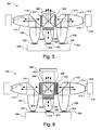
- Fig. 5 illustrates another embodiment of an illumination device 300 that includes a plurality of light sources and a plurality of remote wavelength converting elements.
- Device 300 may be used to produce combined red, green and blue light, which may be used in e.g., a color sequential projector, such as a Digital Light Processing (DLP) projector or a Liquid Crystal on Silicon (LCoS) projector. If desired, additional colors may be produced by device 300, such as cyan and amber.
- DLP Digital Light Processing
- LCDoS Liquid Crystal on Silicon
- Device 300 is similar in operation to device 100, like designated elements being the same. Device 300, however, includes additional LEDs 302 and 322 that are held on respective optional submounts 304 and 324. All the LEDs 102, 302, and 322 may share the same heatsink 306.
- Device 300 generates red and green light using remote phosphor elements 112 and 312, respectively, in the same manner as described above in reference to Fig. 1.
- optical elements such as collimator 308, collimate the primary light, which may be blue or UV light, from LED 302 and dichroic mirror 310 reflects the light towards a second phosphor element 312.
- Collimator 314 focus the light on the phosphor element 312, which is held on a reflective mirror 315 and heatsink 316.
- Converted green light from phosphor element 312 is transmitted through dichroic mirror 310 and transmitted through (or reflected for recycling by) a radiance enhancement film 318 and polarization recovery component 320.
- Device 300 may directly produce blue light, e.g., using an LED 322 with a primary emission in the blue spectrum.
- optical elements such as collimator 328, collimate the blue emitted light, which is transmitted through (or reflected for recycling by) a radiance enhancement film 338 and polarization recovery component 340.
- the use of radiance enhancement films and polarization recovery components increase the radiance and polarization and makes the illumination of the device 300 more uniform.
- radiance enhancement films such as that described in reference to Fig. 2A and 2B may be located before the phosphor elements 112 and 312.
- device 300 may produce blue light in the same manner as described above in reference to Fig. 1, i.e., using an LED with a primary emission in the UV spectrum and using a physically separated phosphor element that converts the primary emission into blue light.
- the necessary components i.e., color separation element, optical elements and phosphor element may extend into or out of the plane of Fig. 5.
- the device 300 includes an X-plate 342, e.g., two dichroic mirrors in a crossed geometry, and a condenser lens 344 to combine the red, green and blue light. If desired, a single radiance enhancement film and polarization recovery component pair may be located between the X-plate 342 and the condenser lens 344 thereby obviating the need for three pairs of radiance enhancement films and polarization recovery components.
- device 300 may produce additional colors, e.g., amber and cyan, using additional LEDs and phosphor elements in the same manner as described in reference to Fig. 1.
- additional LEDs, phosphor elements, and associated optical elements and dichroic mirrors may extend into or out of the plane of the page.
- Fig. 6 illustrates an illumination device 400 that is similar to device 300, like designated elements being the same.
- Device 400 is configured for a three panel LCD projection device, such as the type made by Epson (Japan).
- Device 400 includes an X-cube 402 in front of a projection lens 403.
- the X-cube 402 combines the red, green and blue images generated by microdisplays 404, 406, and 408, respectively, which are, e.g., High Temperature Poly Silicon (HTPS) LCD displays.
- HTPS High Temperature Poly Silicon
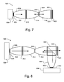
- Fig. 7 illustrates another embodiment of an illumination device 500.
- Device 500 has a linear arrangement of the light source and remote, i.e., physically separate, wavelength converting element, which is particularly advantageous for illumination devices with space limitations, such as a flash light.
- device 500 includes an LED 502 on an optional submount 504 and heat sink 506.
- a collimator 508, or other optical element, collimates the primary light emitted from LED 502, which is transmitted through dichroic mirror 510 towards phosphor element 512.
- a second collimator 514 focuses the primary light that is transmitted through the dichroic mirror 510 to the phosphor element 512.
- the phosphor element 512 absorbs the primary light emitted by LED 502 and emits light having longer wavelengths in both directions, i.e., towards and away from the dichroic mirror 510.
- the dichroic mirror 510 reflects converted light emitted by the phosphor element 512 back towards phosphor element 512.
- dichroic mirror 510 prevents converted light from being incident on the LED 502 thereby improving efficiency of the device 500.
- a portion of the converted light emitted from phosphor element 512 is collimated by collimator 516, or other appropriate optical element.
- a second dichroic mirror 518 transmits the converted light and reflects any unconverted light back towards the phosphor element 512.
- a radiance enhancement film 520 and polarization recovery component 522 may be located after the dichroic mirror 518 to recycle light that cannot be used downstream of the device 500. If desired, an additional radiance enhancement film 524 or polarization recovery component may be located on the phosphor element 512, e.g., as described in reference to Figs. 2A and 2B.
- Fig. 8 is another embodiment of an illumination device 550, which is similar to device 500, like designated elements being the same.
- Device 550 uses an additional light source so that the phosphor element 512 is illuminated from the front and back, thereby approximately doubling the radiance of the device.
- device 550 uses a second LED 552 (on an optional submount 554 and heatsink 556) and a collimator 558 as a second light source.
- a dichroic cube 560 or other appropriate device, such as a dichroic mirror, reflects light emitted by LED 552 towards the phosphor element 512 and transmits converted light from the phosphor element 512.
- the two LEDs 502 and 552 may emit primary light having the same wavelength ranges.
- Illumination device 600 advantageously combines the function of the optical elements and the dichroics using a dichroic sphere 610.
- device 600 includes an LED 602 held on an optional submount 604 and heatsink 606.
- a condenser lens 608, which is held close to or in contact with the LED 602, may be used in conjunction with a dichroic sphere 610 to image the LED 602 onto the phosphor element 612.
- the dichroic sphere 610 may be, e.g., a glass or plastic sphere with a dichroic film deposited in the center, similar to a dichroic cube.
- a condenser lens 614 may be held close to or in contact with the phosphor element 612, which is mounted on a reflective submount 616 and heatsink 618.
- the phosphor element 612 converts the light emitted from the LED 602 to light with longer wavelengths, which is transmitted through the dichroic sphere 610 to lens 620.
- the converted light is collimated or otherwise focused by lens 620.
- a radiance enhancement film 622 and polarization recovery component 624 may be disposed after or before the lens 620.
- Fig. 9B is another illustration of illumination device 600 with the dichroic sphere 610 operating at a more efficient angle.
- dichroics operate with better color separation and efficiency at smaller angles of incidence.
- Fig. 9B illustrates the LED 602 and phosphor element 612 are at an angle of approximately 45 degrees with respect to each other and, thus, the dichroic sphere 610 is at an angle of approximately 22.5 degrees with respect to each of the LED 602 and phosphor element 612.
- other angles may be used, e.g., less than approximately 22.5 degrees.
- Fig. 10 is another embodiment of an illumination device 650 that is similar to device 600 like designated elements being the same.
- Device 650 includes a second LED 652 on an optional submount 654 and heatsink 656, which is optically coupled to the dichroic sphere 660 through, e.g., a condenser lens 658.
- the LEDs 602 and 652 may emit light with different wavelengths.
- the dichroic sphere 660 includes two dichroic mirrors that are responsive to wavelengths emitted by LEDs 602 and 652.
- the phosphor element 612 may include a combination of phosphors for the different wavelengths of light.
- the phosphor element 612 may be at other angles, e.g., approximately 45 degrees or less, with respect to both LED 602 and LED 652 and, thus, the color separation element in dichroic sphere 610 may be at other angles, e.g., approximately 22.5 degrees or less, with respect to each of the LEDs 602 and 652 and the phosphor element 612.
- Fig. 11A illustrates another embodiment of an illumination device 700 that may be used, e.g., as a color sequential projector or a studio or theater light.
- Device 700 is similar to device 100 shown in Fig. 1, like designated elements being the same.
- Device 700 uses a dichroic cube 710 instead of a dichroic mirror 110.
- the wavelength converting element in device 700 is phosphor covered disk 712, which has a highly reflective substrate.
- the disk 712 may have multiple colored sections, each having different types and/or amounts of phosphor.
- Fig. 11B illustrates a plan view of the disk 712, which three different sections of the disk 712 with different types of phosphors.
- the disk 712 is rotated by motor 714. As the disk 712 spins, the different sections of the disk 712, and thus, different phosphors, are illuminated thereby producing different colors. Spinning the disk 712, additionally, may be used to cool the phosphor and can be used to generate air flow for cooling the heatsink 106.
- the color emitted by the device 700 may be controlled by synchronizing the duty cycle of the LED 102 and the spinning of the disk.
- the disk 712 may be held rotated and stopped to illuminate a different portion of the disk 712 when a different color is desired.
- the disk 712 may include multi color phosphors or may contain sections with different messages or symbols, such as logos. The device 700 would thus project the message or symbol, which can then be changed by rotating the disk 712 to illuminate another phosphor message or symbol on the disk 712.
- Fig. 12 illustrates another embodiment of an illumination device 800 that may be used e.g., as backlighting for a liquid crystal display (LCD) panel.
- an LED is used to produce a blue backlight that is used in combination with a phosphor dot pattern consisting of red and green phosphor dots, which are aligned with LCD pixels representing the red and green image pixels, respectively, while the blue pixels are left blank or applied with a non-phosphor scattering material.
- the LED may produce UV light or near UV light wherein blue phosphor dots are used in conjunction with the red and green phosphor dots.
- an LED 802 on an optional submount 804 and heatsink 806, is used with a collimator 808 or other appropriate optical element.
- the LED 802 produces, e.g., blue or UV light.
- a wavelength converting element 812 which includes, e.g., red and green phosphor dots (and blue phosphor dots if the LED 802 produces UV light), is located at end of the collimator 808 opposite the LED 802.
- a dichroic mirror 810 is disposed between the LED 802 and the wavelength converting element 812, e.g., on the LED 802. The dichroic mirror 810 transmits the blue or UV light emitted by the LED 802 but reflects long wavelengths. Thus, substantially all light emitted by the wavelength converting element 812 towards the LED 802 will be reflected by the dichroic mirror 810 and will not be incident on the LED 802.
- a second dichroic mirror 814 is disposed between the wavelength converting element 812 and an LCD panel 816 and lens 818.
- the second dichroic mirror 814 may be configured with a plurality of dichroic elements, each dichroic element being aligned with a corresponding phosphor dot, e.g., red, green and blue dichroic elements are aligned with red, green and blue emitting phosphor dots, respectively.
- the second dichroic mirror 814 is configured to transmit light over a narrow range of angles and reflects light outside the range of angles back towards the wavelength converting element 812 and dichroic mirror 810.
- the pixels in the LCD panel 816 advantageously receive light at a narrow range of angles, thereby improving performance of the device.
- Fig. 13 illustrates an embodiment of a device 850 that includes a semiconductor light emitting device 852, a first dichroic element 854, a wavelength converting element 856, a polarizing element 858, and a second dichroic element 860.
- Some or all of the various elements shown in Fig. 13 may be separated, e.g., by an air gap.
- the various elements 852, 854, 856, 858, and 860 are separated from each other by 1mm or more.
- some or all of the elements shown in Fig. 13 may be in physical contact, i.e., with one element on top and physically contacting the next.
- the semiconductor light emitting device 852 emits light in the blue or UV wavelengths.
- the wavelength converting element 856 converts the light from the semiconductor light emitting device 852 to other wavelengths, e.g., red, green or blue.
- the first dichroic element 854 transmits light that is emitted by the semiconductor light emitting device 852 and reflects light emitted by the wavelength converting element 856.
- the polarizing element 858 which may be omitted if desired, serves a as a polarization recovery component and transmits one polarization state and reflects the other polarization states back to the wavelength converting element 856.
- the second dichroic element 860 serves as a radiance enhancement film by transmitting light emitted by the wavelength converting element 856 over a narrow range of angles, e.g., within 25 degrees from normal, and reflecting light that is outside the range of angles back towards the wavelength converting element 856.
- the second dichroic element 860 also reflects unconverted light from the semiconductor light emitting device 852 that leaked through the wavelength converting element 856 back to the wavelength converting element 856.
- the second dichroic element 860 separates light based on both color and angle of incidence.
- the light that exits the dichroic element 860 is, thus, converted light that is polarized and is within a narrow range of angles.
Abstract
Description
- The present invention is related to an illumination device and, in particular, to wavelength conversion of light produced by high radiance light sources, including semiconductor light emitting devices.
- With the development of efficient light emitting diodes (LEDs) that emit blue light or ultraviolet or near ultraviolet light, commonly referred to herein as UV light, it has become feasible to produce LEDs that generate light through phosphor conversion of a portion of the primary emission of the LED (or the entire primary emission) to longer wavelengths. Conversion of primary emission of the LED to longer wavelengths is commonly referred to as down-conversion of the primary emission. In some systems, an unconverted portion of the primary emission of the LED combines with the converted light of longer wavelengths to produce the desired colored light, e.g., white light. Alternatively, the entire primary emission is converted to light with longer wavelengths and then combined to produce the desired light.
- Conventionally, wavelength conversion of the primary emission of the LED is achieved using a phosphor that is held in a binding medium, such as epoxy, silicone, or other similar material. The phosphor is generally in the form of a powder that is mixed into the binding medium prior to curing. The uncured slurry containing the phosphor powder is deposited onto the LED to encapsulate the LED and subsequently cured.
- It is desirable, however, to use high radiance phosphor-converted LEDs in many illumination applications, such as in projectors, automobile headlights, fiber optics and theater lights. One difficulty with phosphor encapsulated LEDs, however, is that the binding medium turns opaque and turns brown when subjected to high temperatures. This temperature limitation of the encapsulant, accordingly, limits the current at which the LED can be driven, which limits the radiance of the phosphor-converted LED.
- In accordance with an embodiment of the present invention, an illumination device uses a wavelength converting element that is physically separated from a light source, such as a light emitting diode or an array of light emitting diodes, a Xenon lamp or a Mercury lamp. The wavelength converting element, which may be, e.g., a phosphor layer, is additionally optically separated from the light source such that converted light emitted by the wavelength converting element is not incident on the light source. By physically separating the wavelength converting element from the light source, the temperature limitations of the wavelength converting element are removed, thereby permitting the light source to be driven with an increased current to produce a higher radiance. Moreover, by preventing the converted light from being incident on the light source, the conversion and recycling efficiency of the device is improved, which also increases radiance.
- Thus, in one aspect of the present invention, an illumination device includes a light source that emits light having a first wavelength range along a first beam path and a wavelength converting element in the first beam path. The wavelength converting element is physically separated from the light source. The wavelength converting element converts the light having a first wavelength range into light having a second wavelength range along a second beam path. The device further includes a color separation element that is disposed between the light source and the wavelength converting element. The color separation element is configured to prevent substantially all of the light having the second wavelength range from being incident on the light source.
- In another aspect of the present invention, an illumination device includes a light source that emits light having a first wavelength range and a first optical element that is associated with the light source. The first optical element collimates the light emitted from the light source along a first beam path. The illumination device also includes a color separation element in the first beam path, where the color separation element is configured to direct substantially all of the collimated light along the first beam path toward a second optical element. The second optical element focuses the collimated light. A wavelength converting element receives the focused light from the second optical element and is configured to at least partially absorb light of the first wavelength range and to emit light having a second wavelength range. The second optical element collimates the light having the second wavelength range emitted by the wavelength converting element. The color separation element prevents light having a second wavelength range from being incident on the light source.
- In another aspect, a device includes a light source that emits light having a first wavelength range and a first color separation element that receives the emitted light. The first color separation element is configured to direct substantially all of the light emitted by the light source toward a wavelength converting element. The wavelength converting element is configured to at least partially absorb the light of the first wavelength range and to emit light having a second wavelength range. The first color separation element prevents light having a second wavelength range from being incident on the light source.
Additionally, the device includes a second color separation element that receives light emitted by the wavelength converting element. The second color separation element is configured to reflect light in the first wavelength range back to the wavelength converting element, to transmit light in the second wavelength range that is incident on the second color separation element in a first range of angles and to reflect light that is incident on the second color separation element outside the first range of angles. -
- Fig. 1 illustrates an illumination device in accordance with one embodiment of the present invention.
- Figs. 2A and 2B illustrate the operation of the wavelength converting element with a radiance enhancement structure.
- Figs. 3A and 3B illustrate an illumination device used as a headlight.
- Fig. 4 illustrates another embodiment of an illumination device that is similar to the device shown in Fig. 1, but that includes an additional light source to approximately double the radiance of the device.
- Fig. 5 illustrates another embodiment of an illumination device with a plurality of light sources and wavelength converting elements to produce, e.g., combined red, green, and blue light.
- Fig. 6 illustrates another embodiment of an illumination device that is similar to the shown in Fig. 5.
- Fig. 7 illustrates another embodiment of an illumination device that has a linear arrangement of the light source and wavelength converting element.
- Fig. 8 illustrates another embodiment of an illumination device that is similar to the device shown in Fig. 7, but that includes an additional light source to approximately double the radiance of the device.
- Figs. 9A and 9B illustrate another embodiment of an illumination device in which the function of the optical elements and the dichroics are combined in a dichroic sphere.
- Fig. 10 illustrates another embodiment of an illumination device that is similar to the device shown in Fig. 9A, but that includes an additional light source to approximately double the radiance of the device.
- Figs. 11A and 11B illustrate another embodiment of an illumination device that includes a rotating wavelength converting element.
- Fig. 12 illustrates another embodiment of an illumination device that includes a wavelength converting element with phosphor dots, which may be used as backlighting for a liquid crystal display (LCD) panel.
- Fig. 13 illustrates an embodiment of a device that includes a semiconductor light emitting device, a first color separation element, a wavelength converting element, an optional polarization recovery element, and a second color separation element.
-
- In accordance with an embodiment of the present invention, the wavelength converting element is physically separated from the light source, which increases the permissible temperatures and, thus, current at which a semiconductor light emitting device can be driven (if used as the light source). Accordingly, the temperature limitations of the wavelength converting medium will no longer place a limitation on the radiance of the light source. The light source may be, e.g., a semiconductor light emitting device, or other sources of short wavelength radiation, such as a Xenon lamp or mercury lamp. Additionally, the beam path of the wavelength converted light is separated from the light source, i.e., the converted light is prevented from being incident on the light source. Accordingly, absorption losses that may occur in the light source are advantageously reduced thereby providing large efficiency gain in conversion and recycling, which increases radiance.
- Fig. 1 illustrates an
illumination device 100 in accordance with one embodiment of the present invention. Fig. 1 includes alight source 102 that for the sake of simplicity is sometimes referred to herein as a light emitting device (LED) 102. The light source may be a semiconductor light emitting device, such as a light emitting diode or array of light emitting diodes, or other types of light sources that can produce short wavelength light, such as a Xenon lamp or Mercury lamp. By way of example, theLED 102 may be a high radiance device, such as the type described in U.S. Serial No. 10/652,348, entitled "Package for a Semiconductor Light Emitting Device", by Frank Wall et al., filed August 29, 2003, having the same assignee as the present disclosure and which is incorporated herein by reference. TheLED 102 is shown on anoptional submount 104, which is mounted on aheatsink 106. - As shown in Fig. 1,
illumination device 100 includes awavelength converting element 112 that is physically separated from theLED 102. TheLED 102 and thewavelength converting element 112 may be separated along the beam path by, e.g., air, gas or a vacuum. The length of the physical separation of theLED 102 and thewavelength converting element 112 may vary, but in one embodiment is greater than 1mm. The physical separation between theLED 102 and thewavelength converting element 112 is sufficient to prevent substantial conductive heating (ideally the separation is sufficient to prevent any conductive heating) of thewavelength converting element 112 by theLED 102. -
Wavelength converting element 112 may be, e.g., a conventionally produced layer of phosphor or other wavelength converting material in a binding medium, such as epoxy or silicone. The type and amount of phosphor used inwavelength converting element 112 is dependent on the factors such as the primary emission wavelength range of theLED 102 and the desired wavelengths of the converted light. It should be understood thatLED 102 generally produces a primary emission that has a range of wavelengths. The range of wavelengths is generally narrow and, thus, LEDs are sometimes characterized by a single wavelength, which is the dominant or peak wavelength in the spectrum produced. In one embodiment, where theLED 102 produces wavelengths in the blue, UV or near UV spectrum,wavelength converting element 112 may use phosphors such as: Thiogallate (TG), SrSiON:Eu, or SrBaSiO:Eu to produce converted light in the green spectrum; BaSrSiN:Eu to produce converted light in the amber spectrum; CaS:Eu, (Sr0.5,Ca0.5)S:Eu, SrS:Eu, and SrSiN:Eu to produce converted light in the red spectrum; and YAG to produce white converted light. For ease of reference, the wavelength converting element is sometimes referred to herein as a phosphor element, but it should be understood that other wavelength converting materials, such as dyes, may be used. - The
phosphor element 112 is shown mounted on a highlyreflective substrate 115, such as an ESR specular reflecting film manufactured by 3M or E60L white diffuse reflecting film manufactured by Toray, and thermally coupled to aheatsink 116. It should be understood that, if desired, theLED 102 andphosphor element 112 may share the same heatsink if the heatsink is large enough to prevent significant conductive heating of thephosphor element 112. Because thephosphor element 112 is physically separated from theLED 102, the heat produced byLED 102 will have little or no affect on the operation of thephosphor element 112. Accordingly, theLED 102 can be driven with a high current to produce a high radiance. Moreover, with the use of aheatsink 116, heat from thephosphor element 112 caused by phosphor light conversion can be dissipated. Because heating of phosphor can degrade performance by approximately 20 to 30 percent, the use of aheatsink 116 can dramatically increase performance of thephosphor element 112. - In addition, at least a portion of the
beam path 103 of the light emitted fromLED 102 is separate from thebeam path 113 of the converted light fromphosphor element 112.Device 100 uses acolor separation element 110 that reflects wavelengths in the primary light emitted byLED 102 and transmits wavelengths in the converted light emitted byphosphor element 112. In one embodiment, thecolor separation element 110 may be, e.g., a dichroic mirror, and for ease of reference, the color separation element will sometimes be referred to herein as a dichroic mirror. Nevertheless, it should be understood that other color separation elements may be used with the present invention, such as a dichroic cube, a diffractive optical element or a hologram. An adequate dichroic mirror may be purchased from, e.g., Unaxis Balzers Ltd. located in Liechtenstein or Optical Coating Laboratory, Inc. located in Santa Rosa, California. - The
color separation element 110 is used to prevent a substantial amount of the converted light emitted byphosphor element 112 from being incident on theLED 102. Ideally no converted light would be incident on theLED 102, however, color separation elements, such as dichroic mirrors are not ideal and may leak between 0 and 30 percent of the converted light. Accordingly, absorption of the converted light byLED 102 is reduced, thereby improving efficiency in conversion and recycling, and thus in the radiance of theillumination device 100. - Optical elements are used to collimate the primary light and converted light prior to being incident on the
dichroic mirror 110. For example, acollimator 108 between theLED 102 and thedichroic mirror 110 is used to collimate the light emitted byLED 102. Anothercollimator 114 between thephosphor element 112 and thedichroic mirror 110 is used to collimate the converted light emitted by thephosphor element 112, and to focus the primary light reflected by thedichroic mirror 110 onto thephosphor element 112. It should be understood that the optical elements need not be collimators, but may be other optical elements, such as a reflective compound parabolic concentrator element, a total internal reflecting optical element, a rectangular reflective angle transformer, a condenser lens, a lens assembly, or a combination of such elements. Because color separation elements, such as dichroic mirrors, are angle dependent, the optical elements preferably produce a narrow light cone. The optical elements may have, e.g., a circular or rectangular geometry and may be conventionally formed of materials such as molded plastic or metal, such as aluminum, or metal alloys. If theLED 102 is driven at a high temperature, the use of a temperature insensitive material, such as metal or glass is particularly advantageous. - In operation, the
phosphor element 112 receives the primary light from theLED 102 and converts the primary light to another wavelength range by absorbing the primary light and emitting the converted light. Light from theLED 102 that is not absorbed by thephosphor element 112 is reflected by thereflective substrate 115 and reflected back to theLED 102 by thedichroic mirror 110, where the light is reflected back to thephosphor element 112. Thus, the non-absorbed primary light is at least partially recycled inillumination device 100. Additionally, because thephosphor element 112 emits light in all directions, thereflective substrate 115 is used to reflect a portion of the converted light towards thedichroic mirror 110. The converted light is then transmitted by thedichroic mirror 110. - As illustrated in Fig. 1, additional optical elements may be located after the
dichroic mirror 110. By way of example, thedevice 100 may include aradiance enhancement film 118. A radiance enhancement film may be, e.g., a diffractive optical element, such as that manufactured by Heptagon located in Zurich, Switzerland, or a micro refractive element or Brightness Enhancement Film, such as that manufactured by 3M. Additionally,device 100 may include apolarization recovery component 120, sometimes referred to as a non-absorbing polarizer, such as that manufactured by Moxtek, Inc. located in Orem Utah, or by 3M known as a Dual Brightness Enhancement Film. In some embodiments, the relative positions of theradiance enhancement film 118 andpolarization recovery component 120 maybe reversed. - The
radiance enhancement film 118 andpolarization recovery component 120 restrict the angular distribution and polarization state of the light produced byillumination device 100, by transmitting the desired light and reflecting the undesired light back towards thephosphor element 112. Because thephosphor element 112 has very little absorption of the light generated, the recycling efficiency is very high. - It should be understood that while Fig. 1 illustrates the
LED 102 andphosphor element 112 oriented at 90 degrees with respect to each other, other angles may be used. For example, because the color separation and efficiency of dichroic mirrors is angle dependent, it may be desirable for theLED 102 andphosphor element 112 to be oriented at less than 45 degrees with respect to each other. - In one embodiment, a radiance enhancement structure 122 (and/or polarization recovery component) may be mounted over the
phosphor element 112. Figs. 2A and 2B illustrate closer views of the operation of thephosphor element 112 with aradiance enhancement structure 122. Theradiance enhancement structure 122 may be separated from thephosphor element 112 or may be in physical contact with thephosphor element 112. Theradiance enhancement structure 122 is, e.g., a dichroic mirror or diffractive optical element. If a dichroic mirror is used, the dichroic mirror is designed such that the primary light emitted by theLED 102 is transmitted over a large range of incident angles, but that converted light emitted by thephosphor element 112 is transmitted over a limited range of incident angles, e.g., 30 degrees or less from the surface normal, as illustrated in Figs. 2A and 2B. By transmitting converted light at a narrow angle, theradiance enhancement structure 122 ensures that a large percentage of the light will be utilized downstream. - Fig. 2B illustrates that converted light emitted by the
phosphor element 112 at large angles will be reflected by theradiance enhancement structure 122 to be reabsorbed and reemitted by thephosphor element 112. Thus, part of the light will be emitted during a second pass, thereby increasing the radiance of theillumination device 100. - Figs. 3A and 3B illustrate an
illumination device 150 that is similar todevice 100, like designated elements being the same. As illustrated,device 150 is adapted for use as an automobile headlight and includes anenclosure 152 for the components and aprojection lens 154 that produces the resultingbeam 156. A similar configuration may be used as a spot light if desired. - As illustrated in Fig. 3B, the phosphor element 112' may be patterned with different types or amounts of phosphor to form, e.g., a standardized headlight beam pattern. By way of example, as shown in Fig. 3B, a first portion 112'a of the phosphor element 112' may include a blend of yellow and blue phosphor, in which case the
LED 102 emits a lower wavelength range, e.g., UV light. Alternatively, the first portion 112'a may use a yellow phosphor while theLED 102 emits blue light and thedichroic mirror 110 is partially transparent to blue light. The second portion 112'b of the phosphor element 112' may have less or no phosphor or a different blend of phosphor. The portion 112'b with little or no phosphor will convert less light than the portion 112'a. Thedichroic mirror 110 will transmit the light converted by portion 112'a and will reflect most of the unconverted blue light from portion 112'b back towards theLED 102. Thus, the standardized beam pattern formed by portions 112'a and 112'b will be projected by theprojection lens 154. - It should be understood that other patterns may be produced by
illumination device 150 in a similar manner. For example, with proper patterning of the phosphor element 112', messages and/or symbols may be projected by thedevice 150. - Fig. 4 illustrates another embodiment of an
illumination device 200, which is similar todevice 100, like designated elements being the same.Illumination device 200 approximately doubles the radiance with respect todevice 100 by using twoLEDs second LED 202 is held on anoptional submount 204 and may share aheatsink 206 withLED 102. Thesecond LED 202 emits light that is collimated bycollimator 208 and that is reflected towards thephosphor element 112 by a second color separation element, i.e.,dichroic mirror 210. In this embodiment, the light emitted by thesecond LED 202 has a different wavelength range than the light emitted byLED 102. By way of example, theLEDs phosphor element 112 should have a large absorption spectrum or a mixture of phosphors so that the primary light fromLEDs LEDs device 200 has approximately twice the radiance ofdevice 100. - Fig. 5 illustrates another embodiment of an
illumination device 300 that includes a plurality of light sources and a plurality of remote wavelength converting elements.Device 300 may be used to produce combined red, green and blue light, which may be used in e.g., a color sequential projector, such as a Digital Light Processing (DLP) projector or a Liquid Crystal on Silicon (LCoS) projector. If desired, additional colors may be produced bydevice 300, such as cyan and amber. -
Device 300 is similar in operation todevice 100, like designated elements being the same.Device 300, however, includesadditional LEDs optional submounts LEDs same heatsink 306. -
Device 300 generates red and green light usingremote phosphor elements collimator 308, collimate the primary light, which may be blue or UV light, fromLED 302 anddichroic mirror 310 reflects the light towards asecond phosphor element 312.Collimator 314 focus the light on thephosphor element 312, which is held on areflective mirror 315 andheatsink 316. Converted green light fromphosphor element 312 is transmitted throughdichroic mirror 310 and transmitted through (or reflected for recycling by) aradiance enhancement film 318 andpolarization recovery component 320. -
Device 300 may directly produce blue light, e.g., using anLED 322 with a primary emission in the blue spectrum. As illustrated in Fig. 5, optical elements, such ascollimator 328, collimate the blue emitted light, which is transmitted through (or reflected for recycling by) aradiance enhancement film 338 andpolarization recovery component 340. The use of radiance enhancement films and polarization recovery components increase the radiance and polarization and makes the illumination of thedevice 300 more uniform. - If desired, radiance enhancement films, such as that described in reference to Fig. 2A and 2B may be located before the
phosphor elements - Alternatively,
device 300 may produce blue light in the same manner as described above in reference to Fig. 1, i.e., using an LED with a primary emission in the UV spectrum and using a physically separated phosphor element that converts the primary emission into blue light. In an embodiment in which converted blue light is used, the necessary components, i.e., color separation element, optical elements and phosphor element may extend into or out of the plane of Fig. 5. - The
device 300 includes an X-plate 342, e.g., two dichroic mirrors in a crossed geometry, and acondenser lens 344 to combine the red, green and blue light. If desired, a single radiance enhancement film and polarization recovery component pair may be located between the X-plate 342 and thecondenser lens 344 thereby obviating the need for three pairs of radiance enhancement films and polarization recovery components. - If desired,
device 300 may produce additional colors, e.g., amber and cyan, using additional LEDs and phosphor elements in the same manner as described in reference to Fig. 1. The additional LEDs, phosphor elements, and associated optical elements and dichroic mirrors may extend into or out of the plane of the page. - Fig. 6 illustrates an
illumination device 400 that is similar todevice 300, like designated elements being the same.Device 400, however, is configured for a three panel LCD projection device, such as the type made by Epson (Japan).Device 400 includes an X-cube 402 in front of aprojection lens 403. TheX-cube 402 combines the red, green and blue images generated bymicrodisplays - Fig. 7 illustrates another embodiment of an
illumination device 500.Device 500 has a linear arrangement of the light source and remote, i.e., physically separate, wavelength converting element, which is particularly advantageous for illumination devices with space limitations, such as a flash light. As shown in Fig. 7,device 500 includes anLED 502 on anoptional submount 504 andheat sink 506. Acollimator 508, or other optical element, collimates the primary light emitted fromLED 502, which is transmitted throughdichroic mirror 510 towardsphosphor element 512. Asecond collimator 514 focuses the primary light that is transmitted through thedichroic mirror 510 to thephosphor element 512. - The
phosphor element 512 absorbs the primary light emitted byLED 502 and emits light having longer wavelengths in both directions, i.e., towards and away from thedichroic mirror 510. Thedichroic mirror 510 reflects converted light emitted by thephosphor element 512 back towardsphosphor element 512. Thus,dichroic mirror 510 prevents converted light from being incident on theLED 502 thereby improving efficiency of thedevice 500. - A portion of the converted light emitted from
phosphor element 512 is collimated bycollimator 516, or other appropriate optical element. A seconddichroic mirror 518 transmits the converted light and reflects any unconverted light back towards thephosphor element 512. Aradiance enhancement film 520 andpolarization recovery component 522 may be located after thedichroic mirror 518 to recycle light that cannot be used downstream of thedevice 500. If desired, an additionalradiance enhancement film 524 or polarization recovery component may be located on thephosphor element 512, e.g., as described in reference to Figs. 2A and 2B. - Fig. 8 is another embodiment of an
illumination device 550, which is similar todevice 500, like designated elements being the same.Device 550, however, uses an additional light source so that thephosphor element 512 is illuminated from the front and back, thereby approximately doubling the radiance of the device. As shown in Fig. 8,device 550 uses a second LED 552 (on anoptional submount 554 and heatsink 556) and acollimator 558 as a second light source. Adichroic cube 560, or other appropriate device, such as a dichroic mirror, reflects light emitted byLED 552 towards thephosphor element 512 and transmits converted light from thephosphor element 512. The twoLEDs - Fig. 9A is another embodiment of an
illumination device 600.Illumination device 600 advantageously combines the function of the optical elements and the dichroics using adichroic sphere 610. As illustrated in Fig. 9A,device 600 includes anLED 602 held on anoptional submount 604 andheatsink 606. Acondenser lens 608, which is held close to or in contact with theLED 602, may be used in conjunction with adichroic sphere 610 to image theLED 602 onto thephosphor element 612. Thedichroic sphere 610 may be, e.g., a glass or plastic sphere with a dichroic film deposited in the center, similar to a dichroic cube. - A
condenser lens 614 may be held close to or in contact with thephosphor element 612, which is mounted on areflective submount 616 andheatsink 618. Thephosphor element 612 converts the light emitted from theLED 602 to light with longer wavelengths, which is transmitted through thedichroic sphere 610 tolens 620. The converted light is collimated or otherwise focused bylens 620. If desired, aradiance enhancement film 622 andpolarization recovery component 624 may be disposed after or before thelens 620. - Fig. 9B is another illustration of
illumination device 600 with thedichroic sphere 610 operating at a more efficient angle. As discussed above, dichroics operate with better color separation and efficiency at smaller angles of incidence. Thus, Fig. 9B illustrates theLED 602 andphosphor element 612 are at an angle of approximately 45 degrees with respect to each other and, thus, thedichroic sphere 610 is at an angle of approximately 22.5 degrees with respect to each of theLED 602 andphosphor element 612. Of course, other angles may be used, e.g., less than approximately 22.5 degrees. - Fig. 10 is another embodiment of an
illumination device 650 that is similar todevice 600 like designated elements being the same.Device 650, however, includes asecond LED 652 on anoptional submount 654 andheatsink 656, which is optically coupled to thedichroic sphere 660 through, e.g., acondenser lens 658. TheLEDs dichroic sphere 660 includes two dichroic mirrors that are responsive to wavelengths emitted byLEDs phosphor element 612 may include a combination of phosphors for the different wavelengths of light. - If desired, as described in Fig. 9B, the
phosphor element 612 may be at other angles, e.g., approximately 45 degrees or less, with respect to bothLED 602 andLED 652 and, thus, the color separation element indichroic sphere 610 may be at other angles, e.g., approximately 22.5 degrees or less, with respect to each of theLEDs phosphor element 612. - Fig. 11A illustrates another embodiment of an
illumination device 700 that may be used, e.g., as a color sequential projector or a studio or theater light.Device 700 is similar todevice 100 shown in Fig. 1, like designated elements being the same.Device 700, however, uses adichroic cube 710 instead of adichroic mirror 110. Moreover, the wavelength converting element indevice 700 is phosphor covereddisk 712, which has a highly reflective substrate. Thedisk 712 may have multiple colored sections, each having different types and/or amounts of phosphor. Fig. 11B illustrates a plan view of thedisk 712, which three different sections of thedisk 712 with different types of phosphors. - The
disk 712 is rotated bymotor 714. As thedisk 712 spins, the different sections of thedisk 712, and thus, different phosphors, are illuminated thereby producing different colors. Spinning thedisk 712, additionally, may be used to cool the phosphor and can be used to generate air flow for cooling theheatsink 106. - The color emitted by the
device 700 may be controlled by synchronizing the duty cycle of theLED 102 and the spinning of the disk. Alternatively, thedisk 712 may be held rotated and stopped to illuminate a different portion of thedisk 712 when a different color is desired. In another application, thedisk 712 may include multi color phosphors or may contain sections with different messages or symbols, such as logos. Thedevice 700 would thus project the message or symbol, which can then be changed by rotating thedisk 712 to illuminate another phosphor message or symbol on thedisk 712. - Fig. 12 illustrates another embodiment of an
illumination device 800 that may be used e.g., as backlighting for a liquid crystal display (LCD) panel. In this embodiment, an LED is used to produce a blue backlight that is used in combination with a phosphor dot pattern consisting of red and green phosphor dots, which are aligned with LCD pixels representing the red and green image pixels, respectively, while the blue pixels are left blank or applied with a non-phosphor scattering material. If desired, the LED may produce UV light or near UV light wherein blue phosphor dots are used in conjunction with the red and green phosphor dots. - As illustrated in Fig. 12, an
LED 802, on anoptional submount 804 andheatsink 806, is used with acollimator 808 or other appropriate optical element. TheLED 802 produces, e.g., blue or UV light. Awavelength converting element 812, which includes, e.g., red and green phosphor dots (and blue phosphor dots if theLED 802 produces UV light), is located at end of thecollimator 808 opposite theLED 802. Adichroic mirror 810 is disposed between theLED 802 and thewavelength converting element 812, e.g., on theLED 802. Thedichroic mirror 810 transmits the blue or UV light emitted by theLED 802 but reflects long wavelengths. Thus, substantially all light emitted by thewavelength converting element 812 towards theLED 802 will be reflected by thedichroic mirror 810 and will not be incident on theLED 802. - A second
dichroic mirror 814, or radiance enhancing film, is disposed between thewavelength converting element 812 and anLCD panel 816 andlens 818. The seconddichroic mirror 814 may be configured with a plurality of dichroic elements, each dichroic element being aligned with a corresponding phosphor dot, e.g., red, green and blue dichroic elements are aligned with red, green and blue emitting phosphor dots, respectively. As discussed in reference to Figs. 2A and 2B, the seconddichroic mirror 814 is configured to transmit light over a narrow range of angles and reflects light outside the range of angles back towards thewavelength converting element 812 anddichroic mirror 810. For example, light emitted by the phosphor dots at an angle of less than approximately 30 degrees from normal will be transmitted through the seconddichroic mirror 814, while light outside that range is reflected. Accordingly, the pixels in theLCD panel 816 advantageously receive light at a narrow range of angles, thereby improving performance of the device. - Fig. 13 illustrates an embodiment of a
device 850 that includes a semiconductorlight emitting device 852, a firstdichroic element 854, awavelength converting element 856, apolarizing element 858, and a seconddichroic element 860. Some or all of the various elements shown in Fig. 13 may be separated, e.g., by an air gap. For example, in one embodiment, thevarious elements - In this embodiment, the semiconductor
light emitting device 852 emits light in the blue or UV wavelengths. Thewavelength converting element 856 converts the light from the semiconductorlight emitting device 852 to other wavelengths, e.g., red, green or blue. As illustrated by the arrows in Fig. 13, the firstdichroic element 854 transmits light that is emitted by the semiconductorlight emitting device 852 and reflects light emitted by thewavelength converting element 856. Thepolarizing element 858, which may be omitted if desired, serves a as a polarization recovery component and transmits one polarization state and reflects the other polarization states back to thewavelength converting element 856. The seconddichroic element 860 serves as a radiance enhancement film by transmitting light emitted by thewavelength converting element 856 over a narrow range of angles, e.g., within 25 degrees from normal, and reflecting light that is outside the range of angles back towards thewavelength converting element 856. The seconddichroic element 860 also reflects unconverted light from the semiconductorlight emitting device 852 that leaked through thewavelength converting element 856 back to thewavelength converting element 856. Thus, the seconddichroic element 860 separates light based on both color and angle of incidence. The light that exits thedichroic element 860 is, thus, converted light that is polarized and is within a narrow range of angles. - Although the present invention is illustrated in connection with specific embodiments for instructional purposes, the present invention is not limited thereto. Various adaptations and modifications may be made without departing from the scope of the invention. For example, various combinations of elements discussed throughout this disclosure maybe used in accordance with the present invention. Therefore, the spirit and scope of the appended claims should not be limited to the foregoing description.
Claims (59)
- An illumination device comprising:a light source that emits light having a first wavelength range along a first beam path;a wavelength converting element in the first beam path, the wavelength converting element being physically separated from the light source, the wavelength converting element converting the light having a first wavelength range into light having a second wavelength range along a second beam path; anda color separation element disposed between the light source and the wavelength converting element, the color separation element being configured to prevent substantially all of the light having the second wavelength range from being incident on the light source.
- The illumination device of Claim 1, wherein the light source is one of a semiconductor light emitting device, a Xenon lamp, and a Mercury lamp.
- The illumination device of Claim 1, wherein the light source comprises one or more light emitting diodes.
- The illumination device of Claim 1, further comprising at least one of a radiance enhancement film and a polarization recovery component coupled to receive the light emitted from the wavelength converting element.
- The illumination device of Claim 4, wherein the radiance enhancement film comprises at least one of a diffractive optical element and a micro refractive element and wherein the polarization recovery component comprises a non-absorbing polarizer.
- The illumination device of Claim 1, wherein the wavelength converting element is a phosphor.
- The illumination device of Claim 6, wherein the phosphor is patterned.
- The illumination device of Claim 6, wherein the wavelength converting element comprises a rotatable element, the rotatable element having at least a first section being covered with a first phosphor that converts the light having a first wavelength range to the light having the second wavelength range and a second section being covered with a second phosphor that converts the light having a first wavelength range to the light having a third wavelength range, wherein the color separation element is configured to further prevent substantially all of the light having the third wavelength range from being incident on the light source.
- The illumination device of Claim 1, wherein the color separation element is selected from the group consisting of a dichroic mirror, a dichroic cube, a dichroic sphere, a diffractive optical element and a hologram.
- The illumination device of Claim 1, wherein the wavelength converting element is mounted on a reflective submount.
- The illumination device of Claim 1, further comprising a lens, wherein the color separation element reflects the light having a first wavelength range from the light source to the wavelength converting element and transmits the light having the second wavelength range from the wavelength converting element to the lens.
- The illumination device of Claim 1, further comprising:a first optical element disposed between the light source and the color separation element, the first optical element collimates the light emitted from the light source; anda second optical element disposed between the wavelength converting element and the color separation element, the second optical element focuses the collimated light from the light source on the wavelength converting element and collimates the converted light having a second wavelength range.
- The illumination device of Claim 12, wherein the first optical element and the second optical element each include at least one of a collimator, reflective compound parabolic concentrator element, total internal reflecting optical element, a rectangular reflective angle transformer, a condenser lens, and a lens assembly.
- The illumination device of Claim 12, further comprising:wherein the color separation element is a first color separation element that is further disposed between the second light source and the wavelength converting element, the first color separation element configured to transmit substantially all of the light having the second wavelength range and the light having the third wavelength range and to reflect substantially all of the light having a first wavelength range; anda second light source that emits light having a third wavelength range along a third beam path;
a second color separation element disposed between the second light source and the first color separation element, the second color separation element being configured to transmit substantially all of the light having the second wavelength range and to reflect substantially all of the light having the third wavelength range;
wherein the wavelength converting element is in the first beam path and the third beam path, the wavelength converting element converting both the light having the first wavelength range and the light having the third wavelength range into light having the second wavelength range. - The illumination device of Claim 14, further comprising:a third optical element disposed between the second light source and the second color separation element, the third optical element collimates the light emitted from the second light source.
- The illumination device of Claim 12, further comprising:a second light source that emits light having a third wavelength range along a third beam path;a second wavelength converting element in the third beam path, the second wavelength converting element being physically separated from the second light source, the second wavelength converting element converting the light having the third wavelength range to light having a fourth wavelength range along a fourth beam path; anda second color separation element disposed between the second light source and the second wavelength converting element, the second color separation element being configured to prevent substantially all of the light having the fourth wavelength range from the second wavelength converting element from being incident on the second light source; anda third color separation element disposed between the wavelength converting element and the second wavelength converting element, the third color separation element being configured to combine the light having the second wavelength range and the light having the fourth wavelength range.
- The illumination device of Claim 16, further comprising a lens disposed after the third color separation element.
- The illumination device of Claim 16, wherein the third color separation element is one of an X-plate and an X-cube.
- The illumination device of Claim 16, wherein the lens is a condenser lens.
- The illumination device of Claim 16, further comprising a third light source that emits a light having a fifth wavelength range, wherein the third color separation element is further configured to combine the light having the second wavelength range, the light having the fourth wavelength range, and the light having the fifth wavelength range.
- The illumination device of Claim 20, further comprising:a first of at least one of a radiance enhancement film and a polarization recovery component disposed between the color separation element and the third color separation element;a second of at least one of a radiance enhancement film and a polarization recovery component disposed between the second color separation element and the third color separation element; anda third of at least one of a radiance enhancement film and a polarization recovery component disposed between the third light source and the third color separation element.
- The illumination device of Claim 21, further comprising:wherein the lens is a projector lens.a first microdisplay disposed between the first of at least one of a radiance enhancement film and a polarization recovery component and the third color separation element;a second microdisplay disposed between the second of at least one of a radiance enhancement film and a polarization recovery component and the third color separation element; anda third microdisplay disposed between the third of at least one of a radiance enhancement film and a polarization recovery component and the third color separation element;
- The illumination device of Claim 16, further comprising:wherein the third color separation element is further configured to combine the light having the second wavelength range, the light having the fourth wavelength range, and the light having the sixth wavelength range.a third light source that emits light having a fifth wavelength range along a fifth beam path;a third wavelength converting element in the fifth beam path, the third wavelength converting element being physically separated from the third light source, the third wavelength converting element converting the light having the fifth wavelength range to light having a sixth wavelength range along a sixth beam path; anda fourth color separation element disposed between the third light source and the third wavelength converting element, the fourth color separation element being configured to prevent substantially all of the light having the sixth wavelength range from the third wavelength converting element from being incident on the third light source;
- The illumination device of Claim 23, wherein the second wavelength range, fourth wavelength range and sixth wavelength range are in the red, green and blue spectra, respectively.
- The illumination device of Claim 1, wherein the color separation element transmits the light having a first wavelength range from the light source to the wavelength converting element and reflects the light having the second wavelength range from the wavelength converting element back to the wavelength converting element.
- The illumination device of Claim 25, the device further comprising:a first optical element disposed between the light source and the color separation element, the first optical element collimates the light emitted from the light source;a second optical element disposed between the wavelength converting element and the color separation element, the second optical element focuses the collimated light from the light source on the wavelength converting element, wherein the color separation element is disposed between the first optical element and the second optical element; anda third optical element, wherein the wavelength converting element is disposed between the second optical element and the third optical element, the wavelength converting element emits light having the second wavelength range along the second beam path and along a third beam path that is in the opposite direction of the second beam path, the third optical element collimates the light having the second wavelength range along the third beam path and the second optical element collimates the light having the second wavelength range along the second beam path.
- The illumination device of Claim 26, wherein the first optical element, the second optical element, and the third optical element each include at least one of a collimator, reflective compound parabolic concentrator element, total internal reflecting optical element, a rectangular reflective angle transformer, a condenser lens, and a lens assembly.
- The illumination device of Claim 26, further comprising a second color separation element, the wavelength converting element being disposed between the second color separation element and second optical element, the second color separation element transmits light having the second wavelength range and reflects light having the first wavelength range back to the wavelength converting element.
- The illumination device of Claim 26, further comprising
a second light source that emits light having a third wavelength range along a third beam path;
a second color separation element disposed between the second light source and the wavelength converting element, the second color separation element being configured to transmit substantially all of the light having the second wavelength range and to reflect substantially all of the light having the third wavelength range;
a fourth optical element disposed between the second light source and the second color separation element, the fourth optical element collimates the light emitted from the second light source;
wherein the wavelength converting element is in the first beam path and the third beam path, the third optical element focuses the collimated light from the second light source onto the wavelength converting element, the wavelength converting element converts both the light having the first wavelength range and the light having the third wavelength range into light having the second wavelength range. - The illumination device of Claim 26, wherein the first wavelength range and the third wavelength range are approximately the same wavelength range.
- The illumination device of Claim 1, further comprising a second color separation element disposed over the wavelength converting element, the second color separation element configured to transmit light having the first wavelength range over a first range of angles and to transmit light having the second wavelength range over a second range of angles, the second range of angles is smaller than the first range of angles, wherein the second color separation element reflects light having the second wavelength range outside the second range of angles back to the wavelength converting element.
- The illumination device of Claim 31, wherein the second range of angles is approximately 30 degrees.
- The illumination device of Claim 31, wherein the second color separation element is a dichroic mirror.
- The illumination device of Claim 31, wherein the second color separation element is disposed in the beam path between the light source and the wavelength converting element.
- The illumination device of Claim 31, wherein the wavelength converting element is disposed in the beam path between the light source and the second color separation element, the illumination device further comprising a third color separation element that transmits light having the second wavelength range and reflecting light having the first wavelength range, the second color separation element being disposed between the third color separation element and the wavelength converting element.
- The illumination device of Claim 1, further comprising a second color separation element disposed over the wavelength converting element, the second color separation element configured to transmit light having the second wavelength range over a range of angles, wherein the second color separation element reflects light having the second wavelength range outside the range of angles back to the wavelength converting element.
- The illumination device of Claim 36, wherein the wavelength converting element comprises a plurality of phosphor dots, the illumination device further comprising an LCD panel wherein the second color separation element is disposed between the wavelength converting element and the LCD panel.
- The illumination device of Claim 37, further comprising:an optical element disposed between the light source and the wavelength converting element, the optical element collimates the light emitted from the light source; anda lens, the LCD panel being disposed between the second color separation element and the lens.
- The illumination device of Claim 1, wherein the wavelength converting element is physically separated from the light source by more than one millimeter.
- The illumination device of Claim 1, wherein the wavelength converting element is physically separated from the light source by one of air, gas, and vacuum.
- The illumination device of Claim 1, wherein the wavelength converting element is physically separated from the light source sufficiently to prevent substantial conductive heating of the wavelength converting element by the light source.
- A device comprising:a light source that emits light having a first wavelength range;a first optical element associated with the light source, the first optical element collimates the light emitted from the light source along a first beam path;a color separation element in the first beam path, the color separation element configured to direct substantially all of the collimated light along the first beam path toward a second optical element, the second optical element focuses the collimated light; anda wavelength converting element receiving the focused light from the second optical element, the wavelength converting element configured to at least partially absorb light of the first wavelength range and to emit light having a second wavelength range, the second optical element collimates the light having the second wavelength range emitted by the wavelength converting element, wherein the color separation element prevents light having a second wavelength range from being incident on the light source.
- The illumination device of Claim 42, wherein the light source is one of a semiconductor light emitting device, a Xenon lamp, and a Mercury lamp.
- The illumination device of Claim 42, wherein the light source comprises one or more light emitting diodes.
- The device of Claim 42, wherein the color separation element reflects light having a first wavelength range and transmits light having a second wavelength range.
- The device of Claim 45, wherein the wavelength converting element is mounted on a reflective substrate.
- The device of Claim 46, wherein the reflective substrate is mounted on a heatsink.
- The device of Claim 42, wherein the color separation element transmits light having a first wavelength range and reflects light having a second wavelength range.
- The device of Claim 48, further comprising a third optical element, the wavelength converting element being disposed between the second optical element and the third optical element, the third optical element collimates light having a second wavelength range emitted by the wavelength converting element.
- The device of Claim 49, further comprising a second color separation element, the third optical element being disposed between the second color separation element and the wavelength converting element, the second color separation element transmits light having the second wavelength range and reflects light having the first wavelength range.
- A device comprising:a light source that emits light having a first wavelength range;a first color separation element that receives light emitted by the light source, the first color separation element is configured to direct substantially all of the light emitted by the light source toward a wavelength covering element;the wavelength converting element receives the light from the first color separation element, the wavelength converting element is configured to at least partially absorb light of the first wavelength range and to emit light having a second wavelength range, wherein the first color separation element prevents light having a second wavelength range from being incident on the light source; anda second color separation element that receives light emitted by the wavelength converting element, the second color separation element is configured reflect light in the first wavelength range back to the wavelength converting element and to transmit light in the second wavelength range that is incident on the second color separation element in a first range of angles and to reflect light in the second wavelength range that is incident on the second color separation element outside the first range of angles.
- The illumination device of Claim 51, wherein the light source is one of a semiconductor light emitting device, a Xenon lamp, and a Mercury lamp.
- The illumination device of Claim 51, wherein the light source comprises one or more light emitting diodes.
- The device of Claim 51, further comprising a polarization recovery component, wherein the wavelength converting element is disposed between the polarization recover component and the light source.
- The device of Claim 51, wherein the light emitted by the light source having a first wavelength range is reflected by the first color separation element and light emitted by the wavelength converting element having a second wavelength range is transmitted through the first color separation element before being incident on the second color separation element.
- The device of Claim 51, further comprising:a first optical element disposed between the light source and the first color separation element, the first optical element collimates the light emitted from the light source; anda second optical element disposed between the first color separation element and the wavelength converting element, the second optical element focuses the light from the first color separation element towards the wavelength converting element.
- The device of Claim 56, further comprising a third optical element disposed between the wavelength converting element and the second color separation element, the third optical element collimates the light emitted by the wavelength converting element.
- The device of Claim 57, wherein the light emitted by the light source having a first wavelength range is transmitted through the first color separation element and light emitted by the wavelength converting element having a second wavelength range is reflected by the first color separation element.
- The device of Claim 51, wherein the wavelength converting element is physically separated from the light source by one of air, gas, and vacuum.
Priority Applications (3)
| Application Number | Priority Date | Filing Date | Title |
|---|---|---|---|
| PL18167801T PL3383034T3 (en) | 2004-06-04 | 2005-05-30 | Remote wavelength conversion in an illumination device |
| EP19201299.5A EP3621301B9 (en) | 2004-06-04 | 2005-05-30 | Remote wavelength conversion in an illumination device |
| EP18167801.2A EP3383034B1 (en) | 2004-06-04 | 2005-05-30 | Remote wavelength conversion in an illumination device |
Applications Claiming Priority (2)
| Application Number | Priority Date | Filing Date | Title |
|---|---|---|---|
| US861769 | 1992-04-01 | ||
| US10/861,769 US7070300B2 (en) | 2004-06-04 | 2004-06-04 | Remote wavelength conversion in an illumination device |
Related Child Applications (3)
| Application Number | Title | Priority Date | Filing Date |
|---|---|---|---|
| EP18167801.2A Division EP3383034B1 (en) | 2004-06-04 | 2005-05-30 | Remote wavelength conversion in an illumination device |
| EP18167801.2A Division-Into EP3383034B1 (en) | 2004-06-04 | 2005-05-30 | Remote wavelength conversion in an illumination device |
| EP19201299.5A Division EP3621301B9 (en) | 2004-06-04 | 2005-05-30 | Remote wavelength conversion in an illumination device |
Publications (3)
| Publication Number | Publication Date |
|---|---|
| EP1605199A2 true EP1605199A2 (en) | 2005-12-14 |
| EP1605199A3 EP1605199A3 (en) | 2011-01-26 |
| EP1605199B1 EP1605199B1 (en) | 2018-07-11 |
Family
ID=35064478
Family Applications (3)
| Application Number | Title | Priority Date | Filing Date |
|---|---|---|---|
| EP05104602.7A Active EP1605199B1 (en) | 2004-06-04 | 2005-05-30 | Remote wavelength conversion in an illumination device |
| EP18167801.2A Active EP3383034B1 (en) | 2004-06-04 | 2005-05-30 | Remote wavelength conversion in an illumination device |
| EP19201299.5A Active EP3621301B9 (en) | 2004-06-04 | 2005-05-30 | Remote wavelength conversion in an illumination device |
Family Applications After (2)
| Application Number | Title | Priority Date | Filing Date |
|---|---|---|---|
| EP18167801.2A Active EP3383034B1 (en) | 2004-06-04 | 2005-05-30 | Remote wavelength conversion in an illumination device |
| EP19201299.5A Active EP3621301B9 (en) | 2004-06-04 | 2005-05-30 | Remote wavelength conversion in an illumination device |
Country Status (6)
| Country | Link |
|---|---|
| US (1) | US7070300B2 (en) |
| EP (3) | EP1605199B1 (en) |
| JP (3) | JP4920907B2 (en) |
| ES (2) | ES2877064T3 (en) |
| PL (1) | PL3383034T3 (en) |
| TW (1) | TWI343978B (en) |
Cited By (48)
| Publication number | Priority date | Publication date | Assignee | Title |
|---|---|---|---|---|
| EP1677228A1 (en) | 2004-12-28 | 2006-07-05 | Hitachi, Ltd. | Radio frequency identification (RFID) tag, portable terminal, and server for RFID tag |
| EP1734302A1 (en) * | 2005-06-13 | 2006-12-20 | Nichia Corporation | A light emitting device |
| WO2008072185A1 (en) * | 2006-12-15 | 2008-06-19 | Koninklijke Philips Electronics N.V. | Lighting system with dichromatic surfaces |
| WO2008072196A1 (en) * | 2006-12-15 | 2008-06-19 | Philips Lumileds Lighting Company, Llc | Tunable white point light source using a wavelength converting element |
| WO2008081385A2 (en) * | 2006-12-29 | 2008-07-10 | Philips Lumileds Lighting Company, Llc | Illumination device including a color selecting panel for recycling unwanted light |
| EP1963915A1 (en) * | 2005-12-23 | 2008-09-03 | 3M Innovative Properties Company | Polarized, multicolor led-based illumination source |
| EP1974166A2 (en) * | 2006-01-11 | 2008-10-01 | Light Prescriptions Innovators, LLC. | Optical manifold for light-emitting diodes |
| WO2009013695A2 (en) * | 2007-07-25 | 2009-01-29 | Koninklijke Philips Electronics N.V. | Color conversion device and color controllable light-output device |
| DE102008012316A1 (en) * | 2007-09-28 | 2009-04-02 | Osram Opto Semiconductors Gmbh | Semiconductor light source with a primary radiation source and a luminescence conversion element |
| WO2009098621A1 (en) * | 2008-02-08 | 2009-08-13 | Koninklijke Philips Electronics N.V. | Light module device |
| WO2009147582A1 (en) * | 2008-06-04 | 2009-12-10 | Koninklijke Philips Electronics N. V. | Lighting apparatus |
| DE102008030819A1 (en) * | 2008-06-30 | 2009-12-31 | Osram Opto Semiconductors Gmbh | Optoelectronic device |
| EP2181358A1 (en) * | 2007-07-30 | 2010-05-05 | Ylx Corporation | Multicolor illumination device using moving plate with wavelength conversion materials |
| EP1965244A3 (en) * | 2007-02-28 | 2010-08-25 | OSRAM Opto Semiconductors GmbH | Optical device and optical method |
| WO2010106504A1 (en) * | 2009-03-19 | 2010-09-23 | Koninklijke Philips Electronics N.V. | Illumination device with remote luminescent material |
| WO2011059493A1 (en) * | 2009-11-13 | 2011-05-19 | Prism Projection, Inc. | Projection device for architectural and entertainment lighting |
| EP2355524A1 (en) * | 2010-02-05 | 2011-08-10 | Hitachi Consumer Electronics Co. Ltd. | Light source for projection-type display apparatus |
| WO2011098164A1 (en) * | 2010-02-15 | 2011-08-18 | Osram Gesellschaft mit beschränkter Haftung | Light source unit and projector having such a light source unit |
| WO2011116769A1 (en) * | 2010-03-22 | 2011-09-29 | Martin Professional A/S | Projecting device with multiple mutual boosting light sources |
| WO2011160693A1 (en) * | 2010-06-24 | 2011-12-29 | Osram Ag | Light source unit with phosphor element |
| WO2012004713A1 (en) | 2010-07-08 | 2012-01-12 | Koninklijke Philips Electronics N.V. | Projection system comprising a solid state light source and a luminescent material |
| WO2012004705A1 (en) | 2010-07-08 | 2012-01-12 | Koninklijke Philips Electronics N.V. | Projection system comprising a solid state light source and a luminescent material. |
| WO2012077021A1 (en) * | 2010-12-09 | 2012-06-14 | Koninklijke Philips Electronics N.V. | Lighting apparatus for generating light |
| WO2012098020A1 (en) * | 2011-01-21 | 2012-07-26 | Osram Ag | Internally cooled fluorescent device and reflector lamp arrangement comprising said fluorescent device |
| WO2012113610A1 (en) * | 2011-02-23 | 2012-08-30 | Osram Ag | Optical element and lighting device |
| WO2012116733A1 (en) * | 2011-03-01 | 2012-09-07 | Osram Ag | Lighting apparatus with phosphor element |
| EP2506076A1 (en) * | 2011-03-31 | 2012-10-03 | Casio Computer Co., Ltd. | Light source device and projector |
| CN102753883A (en) * | 2010-02-09 | 2012-10-24 | 夏普株式会社 | Lamp comprising a phosphor, radiation source, optical system and heatsink |
| EP2518560A1 (en) * | 2011-04-28 | 2012-10-31 | Sharp Kabushiki Kaisha | Light projection unit and light projection apparatus |
| WO2012154446A1 (en) * | 2011-05-12 | 2012-11-15 | 3M Innovative Properties Company | Optical structure for remote phosphor led |
| WO2013024246A1 (en) * | 2011-08-16 | 2013-02-21 | Eis Optics Limited | Optical wheel |
| CN103032683A (en) * | 2011-09-29 | 2013-04-10 | 卡西欧计算机株式会社 | Phosphor device, illumination apparatus and projector apparatus |
| WO2013087374A1 (en) * | 2011-12-16 | 2013-06-20 | Osram Gmbh | Illumination unit having a luminescent element |
| EP2610540A1 (en) * | 2010-08-26 | 2013-07-03 | Nippon Electric Glass Co., Ltd. | Wavelength conversion element, light source, and backlight unit for liquid crystals |
| EP2642178A1 (en) * | 2010-11-17 | 2013-09-25 | Nec Display Solutions, Ltd | Light source apparatus, lighting apparatus, and projection-type display apparatus |
| EP2687903A1 (en) * | 2011-03-18 | 2014-01-22 | Nec Display Solutions, Ltd | Phosphor-equipped illumination optical system and projector |
| CN103838068A (en) * | 2012-11-23 | 2014-06-04 | 深圳市光峰光电技术有限公司 | Light emitting device and related projection system thereof |
| EP2525703B1 (en) * | 2010-06-22 | 2016-06-22 | OSRAM GmbH | Phosphor device and lighting apparatus comprising the same |
| WO2016120460A1 (en) * | 2015-01-29 | 2016-08-04 | Osram Opto Semiconductors Gmbh | Device for converting the wavelength of electromagnetic radiation |
| EP3065187A1 (en) * | 2015-03-05 | 2016-09-07 | Christie Digital Systems USA, Inc. | Wavelength conversion material array |
| US9470398B2 (en) | 2012-07-23 | 2016-10-18 | Materion Corporation | Compact light engine |
| EP3306392A1 (en) * | 2016-10-06 | 2018-04-11 | Coretronic Corporation | Illumination system and projection apparatus |
| EP2511602B1 (en) * | 2011-03-18 | 2018-05-30 | Stanley Electric Co., Ltd. | Light-emitting device |
| US10101644B2 (en) | 2015-09-14 | 2018-10-16 | Coretronic Corporation | Illumination system and projection apparatus |
| WO2020225195A1 (en) * | 2019-05-09 | 2020-11-12 | Signify Holding B.V. | Improved thermal management in laser-based lighting using a truncated ball lens |
| WO2021204653A1 (en) * | 2020-04-08 | 2021-10-14 | Osram Opto Semiconductors Gmbh | Semiconductor component and process for manufacturing a semiconductor component |
| WO2021204654A1 (en) * | 2020-04-08 | 2021-10-14 | Osram Opto Semiconductors Gmbh | Optoelectronic component |
| AT17653U1 (en) * | 2017-07-10 | 2022-10-15 | Zumtobel Lighting Gmbh | Optical element for influencing a light emitted by an LED light source, arrangement for light emission with such an optical element, and phosphor LED |
Families Citing this family (287)
| Publication number | Priority date | Publication date | Assignee | Title |
|---|---|---|---|---|
| US8075147B2 (en) | 2003-05-13 | 2011-12-13 | Light Prescriptions Innovators, Llc | Optical device for LED-based lamp |
| JP2005316406A (en) * | 2004-03-30 | 2005-11-10 | Sanyo Electric Co Ltd | Optical member, illumination apparatus and projection-type image display apparatus |
| US7724440B2 (en) * | 2004-04-23 | 2010-05-25 | Light Prescriptions Innovators, Llc | Combining outputs of different light sources |
| JP2008515216A (en) * | 2004-09-30 | 2008-05-08 | コーニンクレッカ フィリップス エレクトロニクス エヌ ヴィ | Brightness enhancement of LEDs using selective ray angular reuse |
| KR100644632B1 (en) * | 2004-10-01 | 2006-11-10 | 삼성전자주식회사 | Illumination unit adopting LED and projection display using the same |
| KR100683171B1 (en) * | 2005-03-08 | 2007-02-15 | 삼성전자주식회사 | Cooling apparatus and projector having the same |
| TW200634257A (en) * | 2005-03-24 | 2006-10-01 | Coretronic Corp | Illumination system |
| US7234820B2 (en) * | 2005-04-11 | 2007-06-26 | Philips Lumileds Lighting Company, Llc | Illuminators using reflective optics with recycling and color mixing |
| US7445340B2 (en) * | 2005-05-19 | 2008-11-04 | 3M Innovative Properties Company | Polarized, LED-based illumination source |
| CN101185022B (en) * | 2005-05-31 | 2011-03-23 | 精工爱普生株式会社 | Illumination arrangements for colored light sources |
| US8718437B2 (en) | 2006-03-07 | 2014-05-06 | Qd Vision, Inc. | Compositions, optical component, system including an optical component, devices, and other products |
| WO2006133214A2 (en) * | 2005-06-07 | 2006-12-14 | Optical Research Associates | Phosphor wheel illuminator |
| US7543959B2 (en) * | 2005-10-11 | 2009-06-09 | Philips Lumiled Lighting Company, Llc | Illumination system with optical concentrator and wavelength converting element |
| KR101281342B1 (en) * | 2005-11-22 | 2013-07-02 | 쓰리엠 이노베이티브 프로퍼티즈 컴파니 | Arrays of Light Emitting Articles and Method of Manufacturing Same |
| WO2007070821A2 (en) * | 2005-12-13 | 2007-06-21 | Ilight Technologies, Inc. | Illumination device with hue transformation |
| WO2007081719A2 (en) | 2006-01-05 | 2007-07-19 | Illumitex, Inc. | Separate optical device for directing light from an led |
| US20070165186A1 (en) * | 2006-01-13 | 2007-07-19 | Copner Nigel J | Light source system and an image projection system |
| US9874674B2 (en) | 2006-03-07 | 2018-01-23 | Samsung Electronics Co., Ltd. | Compositions, optical component, system including an optical component, devices, and other products |
| EP2041478B1 (en) | 2006-03-07 | 2014-08-06 | QD Vision, Inc. | An article including semiconductor nanocrystals |
| JP2007311114A (en) * | 2006-05-17 | 2007-11-29 | Olympus Corp | Lighting optical system using solid light emitting element emitting white light, and optical device equipped with it |
| EP2038577B1 (en) * | 2006-06-02 | 2018-04-25 | Philips Lighting Holding B.V. | Colored and white light generating lighting device |
| US7663152B2 (en) * | 2006-08-09 | 2010-02-16 | Philips Lumileds Lighting Company, Llc | Illumination device including wavelength converting element side holding heat sink |
| DE102006045704A1 (en) * | 2006-09-27 | 2008-04-03 | Osram Opto Semiconductors Gmbh | Optical element and optoelectronic component with such an optical element |
| JP2010506402A (en) | 2006-10-02 | 2010-02-25 | イルミテックス, インコーポレイテッド | LED system and method |
| US20100051970A1 (en) * | 2006-11-17 | 2010-03-04 | Ouderkirk Andrew J | Planarized led with optical extractor |
| WO2008064070A1 (en) * | 2006-11-17 | 2008-05-29 | 3M Innovative Properties Company | Optical bonding composition for led light source |
| CN101548398A (en) * | 2006-11-20 | 2009-09-30 | 3M创新有限公司 | Optical bonding composition for LED light source |
| JP4561732B2 (en) * | 2006-11-20 | 2010-10-13 | トヨタ自動車株式会社 | Mobile positioning device |
| US7905605B2 (en) * | 2006-12-13 | 2011-03-15 | Koninklijke Philips Electronics N.V. | Multi-primary LED projection system |
| US8836212B2 (en) | 2007-01-11 | 2014-09-16 | Qd Vision, Inc. | Light emissive printed article printed with quantum dot ink |
| US20080198572A1 (en) * | 2007-02-21 | 2008-08-21 | Medendorp Nicholas W | LED lighting systems including luminescent layers on remote reflectors |
| US8203260B2 (en) * | 2007-04-13 | 2012-06-19 | Intematix Corporation | Color temperature tunable white light source |
| EP2140502B1 (en) * | 2007-04-17 | 2017-04-05 | Philips Lighting Holding B.V. | Illumination system |
| US20080260328A1 (en) * | 2007-04-20 | 2008-10-23 | 3M Innovative Properties Company | Led light extraction bar and injection optic for thin lightguide |
| US20080260329A1 (en) * | 2007-04-20 | 2008-10-23 | 3M Innovative Properties Company | Lightguides having curved light injectors |
| US7703943B2 (en) | 2007-05-07 | 2010-04-27 | Intematix Corporation | Color tunable light source |
| CN101680606B (en) * | 2007-05-24 | 2013-01-02 | 皇家飞利浦电子股份有限公司 | Color-tunable illumination system |
| US7744241B2 (en) * | 2007-06-13 | 2010-06-29 | Ylx, Ltd. | High brightness light source using light emitting devices of different wavelengths and wavelength conversion |
| WO2009014707A2 (en) | 2007-07-23 | 2009-01-29 | Qd Vision, Inc. | Quantum dot light enhancement substrate and lighting device including same |
| US8128249B2 (en) | 2007-08-28 | 2012-03-06 | Qd Vision, Inc. | Apparatus for selectively backlighting a material |
| US8907368B2 (en) * | 2007-11-08 | 2014-12-09 | Dialight Corporation | Double collimator LED color mixing system |
| JP5451629B2 (en) * | 2007-11-19 | 2014-03-26 | コーニンクレッカ フィリップス エヌ ヴェ | Light source and illumination system having a predetermined appearance |
| US20090153805A1 (en) * | 2007-12-14 | 2009-06-18 | Fu Zhun Precision Industry (Shen Zhen) Co., Ltd. | Portable projector with a heat dissipation system |
| US8147081B2 (en) * | 2007-12-26 | 2012-04-03 | Lumination Llc | Directional linear light source |
| TWI341376B (en) * | 2007-12-31 | 2011-05-01 | Ind Tech Res Inst | Illuminating apparatus of a polarization light |
| US8096668B2 (en) * | 2008-01-16 | 2012-01-17 | Abu-Ageel Nayef M | Illumination systems utilizing wavelength conversion materials |
| DE102008017071A1 (en) * | 2008-01-31 | 2009-08-06 | Osram Opto Semiconductors Gmbh | Optoelectronic module and projection device with the optoelectronic module |
| CN101939849A (en) | 2008-02-08 | 2011-01-05 | 伊鲁米特克有限公司 | Be used for the system and method that emitter layer is shaped |
| CN102016402A (en) * | 2008-02-21 | 2011-04-13 | 光处方革新有限公司 | Spherically emitting remote phosphor |
| DE102008011866B4 (en) * | 2008-02-29 | 2018-05-03 | Osram Opto Semiconductors Gmbh | Light source arrangement with a semiconductor light source |
| US20090234338A1 (en) * | 2008-03-11 | 2009-09-17 | Shaser, Inc. | Reducing sensations experienced during light-based dermatologic treatment procedures |
| WO2009115976A1 (en) * | 2008-03-20 | 2009-09-24 | Koninklijke Philips Electronics N.V. | Illumination system comprising a luminescent element with a heat sink |
| US8116005B2 (en) * | 2008-04-04 | 2012-02-14 | Texas Instruments Incorporated | Light combiner |
| JP4662183B2 (en) * | 2008-04-16 | 2011-03-30 | カシオ計算機株式会社 | Light source device and projector |
| US9207385B2 (en) | 2008-05-06 | 2015-12-08 | Qd Vision, Inc. | Lighting systems and devices including same |
| WO2009137053A1 (en) | 2008-05-06 | 2009-11-12 | Qd Vision, Inc. | Optical components, systems including an optical component, and devices |
| EP2297762B1 (en) | 2008-05-06 | 2017-03-15 | Samsung Electronics Co., Ltd. | Solid state lighting devices including quantum confined semiconductor nanoparticles |
| RU2503093C2 (en) | 2008-06-10 | 2013-12-27 | Конинклейке Филипс Электроникс Н.В. | Led module |
| JP5527571B2 (en) * | 2008-09-30 | 2014-06-18 | カシオ計算機株式会社 | Light emitting device, light source device, and projector using the light source device |
| TW201034256A (en) | 2008-12-11 | 2010-09-16 | Illumitex Inc | Systems and methods for packaging light-emitting diode devices |
| RU2011134870A (en) * | 2009-01-21 | 2013-02-27 | Конинклейке Филипс Электроникс Н.В. | A SOURCE OF OPTICAL RADIATION CONTAINING A LIGHT ENERGY RECYCLING DEVICE, AND THE RELATED LIGHT ENERGY RECYCLING DEVICE |
| JP4900736B2 (en) * | 2009-03-31 | 2012-03-21 | カシオ計算機株式会社 | Light source device and projector |
| US8104907B2 (en) * | 2009-04-29 | 2012-01-31 | Koninklijke Philips Electronics N.V. | Remote wavelength converting material configuration for lighting |
| DE102009024941A1 (en) * | 2009-06-09 | 2010-12-23 | Carl Zeiss Surgical Gmbh | Lighting device and medical-optical observation device |
| JP4711021B2 (en) * | 2009-06-30 | 2011-06-29 | カシオ計算機株式会社 | Projection device |
| JP5581629B2 (en) | 2009-08-20 | 2014-09-03 | セイコーエプソン株式会社 | projector |
| JP5504747B2 (en) * | 2009-08-20 | 2014-05-28 | セイコーエプソン株式会社 | projector |
| US8449128B2 (en) | 2009-08-20 | 2013-05-28 | Illumitex, Inc. | System and method for a lens and phosphor layer |
| US8585253B2 (en) | 2009-08-20 | 2013-11-19 | Illumitex, Inc. | System and method for color mixing lens array |
| JP5407664B2 (en) * | 2009-08-27 | 2014-02-05 | セイコーエプソン株式会社 | projector |
| JP5333852B2 (en) * | 2009-09-14 | 2013-11-06 | カシオ計算機株式会社 | projector |
| JP5370764B2 (en) * | 2009-09-15 | 2013-12-18 | カシオ計算機株式会社 | Light source device and projector |
| WO2011033394A1 (en) * | 2009-09-16 | 2011-03-24 | Koninklijke Philips Electronics N.V. | Light emitter with predefined angular color point distribution |
| JP5796272B2 (en) * | 2009-09-28 | 2015-10-21 | カシオ計算機株式会社 | Light source device, projection device, and projection method |
| JP2011108502A (en) * | 2009-11-18 | 2011-06-02 | Stanley Electric Co Ltd | Light source device and illuminating device |
| JP5507214B2 (en) * | 2009-11-19 | 2014-05-28 | スタンレー電気株式会社 | Light source device and lighting device |
| JP2011124002A (en) * | 2009-12-08 | 2011-06-23 | Stanley Electric Co Ltd | Light source device and lighting system |
| JP5375581B2 (en) * | 2009-12-17 | 2013-12-25 | セイコーエプソン株式会社 | Lighting device and projector |
| US8348430B2 (en) * | 2009-12-17 | 2013-01-08 | Alcon Research, Ltd. | Photonic lattice LEDs for ophthalmic illumination |
| JP5428078B2 (en) * | 2009-12-21 | 2014-02-26 | カシオ計算機株式会社 | Light source device and projector |
| JP5495023B2 (en) * | 2009-12-21 | 2014-05-21 | カシオ計算機株式会社 | Light source unit and projector |
| WO2011078924A1 (en) * | 2009-12-22 | 2011-06-30 | Alcon Research, Ltd. | Thermoelectric cooling for increased brightness in a white light l.e.d. illuminator |
| CA2780352A1 (en) * | 2009-12-22 | 2011-06-30 | Alcon Research, Ltd. | Light collector for a white light led illuminator |
| JP5428079B2 (en) * | 2009-12-25 | 2014-02-26 | カシオ計算機株式会社 | Fluorescent light emitting device and projector |
| JP5618379B2 (en) * | 2009-12-28 | 2014-11-05 | シャープ株式会社 | Lighting device |
| JP4991001B2 (en) | 2009-12-28 | 2012-08-01 | シャープ株式会社 | Lighting device |
| EP3168684A1 (en) * | 2010-01-29 | 2017-05-17 | NEC Display Solutions, Ltd. | Illumination optical system and projector using the same |
| JP5473021B2 (en) * | 2010-01-29 | 2014-04-16 | Necディスプレイソリューションズ株式会社 | Illumination optical system and projector using the same |
| JP5550368B2 (en) * | 2010-02-03 | 2014-07-16 | スタンレー電気株式会社 | Light source device and lighting device |
| JP5423442B2 (en) * | 2010-02-04 | 2014-02-19 | セイコーエプソン株式会社 | Lighting device and projector |
| JP5671666B2 (en) * | 2010-02-12 | 2015-02-18 | 日立マクセル株式会社 | Solid light source device and projection display device |
| DE102010001945B4 (en) | 2010-02-15 | 2019-07-25 | Osram Gmbh | Light source unit and projector with such a light source unit |
| US8646949B2 (en) * | 2010-03-03 | 2014-02-11 | LumenFlow Corp. | Constrained folded path resonant white light scintillator |
| JP5556256B2 (en) * | 2010-03-11 | 2014-07-23 | パナソニック株式会社 | Illumination device and projection-type image display device |
| US8384105B2 (en) | 2010-03-19 | 2013-02-26 | Micron Technology, Inc. | Light emitting diodes with enhanced thermal sinking and associated methods of operation |
| US9314374B2 (en) * | 2010-03-19 | 2016-04-19 | Alcon Research, Ltd. | Stroboscopic ophthalmic illuminator |
| JP5527594B2 (en) * | 2010-03-24 | 2014-06-18 | カシオ計算機株式会社 | Light source unit and projector |
| JP5515941B2 (en) * | 2010-03-26 | 2014-06-11 | セイコーエプソン株式会社 | projector |
| JP5539768B2 (en) * | 2010-03-29 | 2014-07-02 | 京セラ株式会社 | Lighting device |
| JP5445854B2 (en) * | 2010-03-29 | 2014-03-19 | カシオ計算機株式会社 | Light emitting unit and projector |
| US8936377B2 (en) | 2010-03-31 | 2015-01-20 | Alcon Research, Ltd. | Apparatus for enhancing brightness of a wavelength converting element |
| CN102213383B (en) * | 2010-04-01 | 2013-08-14 | 中强光电股份有限公司 | Light source module and wavelength conversion module |
| US8474997B2 (en) * | 2010-04-07 | 2013-07-02 | Appotronics Corporation Limited | High brightness illumination device using double-sided excitation of wavelength conversion materials |
| WO2011127622A1 (en) * | 2010-04-12 | 2011-10-20 | 绎立锐光科技开发(深圳)有限公司 | Method for improving emitted light color based on light wavelength conversion |
| TWI438490B (en) * | 2010-05-14 | 2014-05-21 | Delta Electronics Inc | Light source system and projection apparatus using the same |
| US9039187B2 (en) | 2010-05-21 | 2015-05-26 | Nec Display Solutions, Ltd. | Illumination optical system and a projector using the same |
| US20130057833A1 (en) * | 2010-05-21 | 2013-03-07 | Nec Display Solutions, Ltd. | Illumination optical system and a projector using the same |
| JP5770433B2 (en) | 2010-06-18 | 2015-08-26 | ソニー株式会社 | Light source device and image projection device |
| JP5429079B2 (en) * | 2010-06-30 | 2014-02-26 | 株式会社Jvcケンウッド | Light source device and projection display device |
| JP2012013898A (en) * | 2010-06-30 | 2012-01-19 | Jvc Kenwood Corp | Light source unit and projection-type display apparatus |
| US8941135B2 (en) | 2010-07-15 | 2015-01-27 | Nitto Denko Corporation | Light emissive ceramic laminate and method of making same |
| JP5474698B2 (en) * | 2010-07-29 | 2014-04-16 | 三洋電機株式会社 | Light source device and projection display device |
| JP5257420B2 (en) * | 2010-08-04 | 2013-08-07 | ウシオ電機株式会社 | Light source device |
| JP5573473B2 (en) * | 2010-08-06 | 2014-08-20 | セイコーエプソン株式会社 | Light source device and projector |
| CN102375314B (en) * | 2010-08-09 | 2013-12-04 | 台达电子工业股份有限公司 | Illumination system and projector using the same |
| DE102010034054A1 (en) * | 2010-08-11 | 2012-02-16 | Schott Ag | Laser-based white light source |
| WO2012024591A1 (en) | 2010-08-20 | 2012-02-23 | Research Triangle Institute, International | Photoluminescent nanofiber composites, methods for fabrication, and related lighting devices |
| WO2012024607A2 (en) | 2010-08-20 | 2012-02-23 | Research Triangle Institute, International | Lighting devices utilizing optical waveguides and remote light converters, and related methods |
| EP2606275A2 (en) | 2010-08-20 | 2013-06-26 | Research Triangle Institute, International | Color-tunable lighting devices and methods for tunning color output of lighting devices |
| CN103068301A (en) * | 2010-08-24 | 2013-04-24 | 欧司朗有限公司 | Phosphor device and lighting apparatus comprising the same |
| US9188311B2 (en) * | 2010-08-24 | 2015-11-17 | Osram Gmbh | Phosphor device and lighting apparatus comprising the same |
| JP5601092B2 (en) * | 2010-08-27 | 2014-10-08 | セイコーエプソン株式会社 | Lighting device and projector |
| US8573801B2 (en) | 2010-08-30 | 2013-11-05 | Alcon Research, Ltd. | LED illuminator |
| WO2012030764A2 (en) * | 2010-08-30 | 2012-03-08 | Neolac, Inc. | Human milk preparation |
| TWI425295B (en) | 2010-09-28 | 2014-02-01 | Delta Electronics Inc | Illumination system and projection device comprising the same |
| US8415642B2 (en) | 2010-09-30 | 2013-04-09 | Performance Indicator, Llc | Photolytically and environmentally stable multilayer structure for high efficiency electromagnetic energy conversion and sustained secondary emission |
| US8664624B2 (en) | 2010-09-30 | 2014-03-04 | Performance Indicator Llc | Illumination delivery system for generating sustained secondary emission |
| CN102445827B (en) * | 2010-09-30 | 2014-08-20 | 台达电子工业股份有限公司 | Light source system and projection device |
| JP2012079989A (en) * | 2010-10-05 | 2012-04-19 | Stanley Electric Co Ltd | Light source device and lighting fixture |
| US9140429B2 (en) | 2010-10-14 | 2015-09-22 | Cree, Inc. | Optical element edge treatment for lighting device |
| US8455882B2 (en) * | 2010-10-15 | 2013-06-04 | Cree, Inc. | High efficiency LEDs |
| CN102455512B (en) | 2010-10-21 | 2014-03-12 | 中强光电股份有限公司 | Illumination device and projection device |
| JP2012108486A (en) * | 2010-10-21 | 2012-06-07 | Panasonic Corp | Light source device and image display |
| JP5255040B2 (en) * | 2010-10-29 | 2013-08-07 | シャープ株式会社 | LIGHT EMITTING DEVICE, VEHICLE HEADLAMP, LIGHTING DEVICE AND VEHICLE, AND LIGHT EMITTING DEVICE ASSEMBLING METHOD |
| JP5487077B2 (en) * | 2010-10-29 | 2014-05-07 | シャープ株式会社 | Light emitting device, vehicle headlamp and lighting device |
| JP5336564B2 (en) * | 2010-10-29 | 2013-11-06 | シャープ株式会社 | Light emitting device, lighting device, vehicle headlamp, and vehicle |
| TWI421620B (en) | 2010-11-03 | 2014-01-01 | Delta Electronics Inc | Light source adjusting device and projection system comprising the same |
| US8491140B2 (en) | 2010-11-05 | 2013-07-23 | Cree, Inc. | Lighting device with multiple emitters and remote lumiphor |
| US9648673B2 (en) | 2010-11-05 | 2017-05-09 | Cree, Inc. | Lighting device with spatially segregated primary and secondary emitters |
| JP5606634B2 (en) * | 2010-11-09 | 2014-10-15 | オスラム ゲーエムベーハー | Fluorescent assembly with fluorescent element and optical system, light source unit with fluorescent assembly, method for converting light using fluorescent assembly, and use of fluorescent assembly or light source unit |
| CN103201678B (en) * | 2010-11-09 | 2016-01-20 | Nec显示器解决方案株式会社 | Lighting device and the projection display device using it |
| CN102466956B (en) * | 2010-11-11 | 2014-05-28 | 台达电子工业股份有限公司 | Light source regulator and projection system having same |
| JP5695887B2 (en) * | 2010-11-18 | 2015-04-08 | スタンレー電気株式会社 | Light source device and lighting device |
| JP5629559B2 (en) * | 2010-11-19 | 2014-11-19 | スタンレー電気株式会社 | Light source device and lighting device |
| JP5895226B2 (en) * | 2010-11-30 | 2016-03-30 | パナソニックIpマネジメント株式会社 | Light source device and projection display device |
| JP2012119193A (en) | 2010-12-01 | 2012-06-21 | Sharp Corp | Light-emitting device, vehicular headlamp, lighting device, and vehicle |
| DE102010062463A1 (en) * | 2010-12-06 | 2012-06-06 | Osram Ag | Lighting-device i.e. vehicle headlight, has phosphor regions individually illuminatable by respective light sources, and aligned for diffuse radiation of light on downstream optical elements, which exhibit different optical properties |
| WO2012075949A1 (en) | 2010-12-08 | 2012-06-14 | 绎立锐光科技开发(深圳)有限公司 | Light source |
| EP2466375B1 (en) * | 2010-12-17 | 2019-12-25 | Maxell, Ltd. | Light Source Apparatus |
| WO2012088454A1 (en) | 2010-12-22 | 2012-06-28 | Energy Focus, Inc. | An elongated led lighting arrangement |
| WO2012091971A1 (en) | 2010-12-29 | 2012-07-05 | 3M Innovative Properties Company | Remote phosphor led constructions |
| US9159885B2 (en) | 2010-12-29 | 2015-10-13 | 3M Innovative Properties Company | Remote phosphor LED device with broadband output and controllable color |
| WO2012099966A2 (en) * | 2011-01-18 | 2012-07-26 | Whiteoptics Llc | Color-shifting reflector |
| TWI432780B (en) | 2011-01-19 | 2014-04-01 | 台達電子工業股份有限公司 | Illumination system |
| JP5780153B2 (en) * | 2011-01-24 | 2015-09-16 | 株式会社Jvcケンウッド | Light source device and projection display device |
| JP5759198B2 (en) * | 2011-02-10 | 2015-08-05 | セイコーエプソン株式会社 | Light emitting device, light source device and projector |
| US20120209358A1 (en) * | 2011-02-15 | 2012-08-16 | Feng Xiao-Fan | Color adaptive therapeutic light control system |
| JP5788194B2 (en) | 2011-03-03 | 2015-09-30 | シャープ株式会社 | Light emitting device, lighting device, and vehicle headlamp |
| TWI427397B (en) * | 2011-03-23 | 2014-02-21 | Delta Electronics Inc | Illumination system |
| JP5348163B2 (en) * | 2011-03-23 | 2013-11-20 | カシオ計算機株式会社 | Light source device and projector |
| JP5223941B2 (en) * | 2011-03-28 | 2013-06-26 | カシオ計算機株式会社 | Projection device |
| WO2012154433A2 (en) * | 2011-05-12 | 2012-11-15 | 3M Innovative Properties Company | Remote phosphor polarization converter |
| WO2012154431A2 (en) * | 2011-05-12 | 2012-11-15 | 3M Innovative Properties Company | Remote phosphor converted led |
| JP5870259B2 (en) * | 2011-05-25 | 2016-02-24 | パナソニックIpマネジメント株式会社 | Illumination device and projection display device including the illumination device |
| DE102011080179A1 (en) * | 2011-08-01 | 2013-02-07 | Osram Ag | Wavelength conversion body and method for its production |
| GB201114495D0 (en) * | 2011-08-23 | 2011-10-05 | Cymtec Ltd | Radiation generating apparatus and a method of generating radiation |
| US9612511B2 (en) * | 2011-08-25 | 2017-04-04 | Appotronics Corporation Limited | Projection system using excitable wavelength conversion material in the light source |
| US9075299B2 (en) * | 2011-08-27 | 2015-07-07 | Appotronics Corporation Limited | Light source with wavelength conversion device and filter plate |
| CN105549311B (en) * | 2011-08-27 | 2018-11-13 | 深圳市光峰光电技术有限公司 | Optical projection system and its light-emitting device |
| JP2013047736A (en) * | 2011-08-29 | 2013-03-07 | Mitsubishi Electric Corp | Light source device and projection type display device |
| JP5804536B2 (en) * | 2011-09-13 | 2015-11-04 | Necディスプレイソリューションズ株式会社 | Illumination optical system and projection display device |
| US8919993B2 (en) * | 2011-09-17 | 2014-12-30 | Appotronics Corporation Limited | High recycling efficiency solid state light source device |
| JP5252053B2 (en) * | 2011-09-20 | 2013-07-31 | カシオ計算機株式会社 | Light source unit and projector |
| US10688527B2 (en) | 2011-09-22 | 2020-06-23 | Delta Electronics, Inc. | Phosphor device comprising plural phosphor agents for converting waveband light into plural color lights with different wavelength peaks |
| TWI448806B (en) | 2011-09-22 | 2014-08-11 | Delta Electronics Inc | Phosphor device and illumination system and projection equipment with the same |
| US10310363B2 (en) | 2011-09-22 | 2019-06-04 | Delta Electronics, Inc. | Phosphor device with spectrum of converted light comprising at least a color light |
| CN103034035A (en) * | 2011-09-30 | 2013-04-10 | 中强光电股份有限公司 | Illuminating system and projecting apparatus |
| JP5834723B2 (en) * | 2011-09-30 | 2015-12-24 | カシオ計算機株式会社 | Light source device and projector device |
| KR20130036472A (en) * | 2011-10-04 | 2013-04-12 | 엘지전자 주식회사 | Display device having wavelength converting layer |
| WO2013050733A1 (en) * | 2011-10-07 | 2013-04-11 | Cymtec Ltd | Radiation generating apparatus and a method of generating radiation |
| TWM426048U (en) | 2011-10-07 | 2012-04-01 | Benq Corp | Light source module and projector using the same |
| US9195123B2 (en) | 2011-10-13 | 2015-11-24 | Texas Instruments Corporated | Projector light source and system, including configuration for display of 3D images |
| US9816683B2 (en) * | 2011-10-20 | 2017-11-14 | Appotronics Corporation Limited | Light sources system and projection device using the same |
| US9442357B2 (en) | 2011-10-25 | 2016-09-13 | Texas Instruments Incorporated | Spectral filtering of phosphor color wheels |
| CN102393598B (en) * | 2011-11-03 | 2014-03-26 | 海信集团有限公司 | Light source device and projector adopting same |
| CN104880899B (en) | 2011-12-04 | 2017-06-20 | 深圳市光峰光电技术有限公司 | Light-emitting device and its optical projection system of application |
| CN102722073B (en) * | 2011-12-18 | 2014-12-31 | 深圳市光峰光电技术有限公司 | Light source system and projector |
| DE102012101663B4 (en) | 2012-02-29 | 2019-12-24 | Osram Opto Semiconductors Gmbh | Conversion element, illuminant and method for producing a conversion element |
| JP5660074B2 (en) * | 2012-04-20 | 2015-01-28 | カシオ計算機株式会社 | Light source device and projector |
| US9952442B2 (en) | 2012-05-24 | 2018-04-24 | Excelitas Canada, Inc. | High brightness solid state illumination system for fluorescence imaging and analysis |
| US9239133B2 (en) | 2012-05-24 | 2016-01-19 | Excelitas Canada, Inc. | High brightness solid state illumination system for fluorescence imaging and analysis |
| JP6019762B2 (en) * | 2012-05-30 | 2016-11-02 | 日亜化学工業株式会社 | Light source device and projector provided with the light source device |
| JP2013254889A (en) * | 2012-06-08 | 2013-12-19 | Idec Corp | Light-source apparatus and lighting apparatus |
| US9810942B2 (en) * | 2012-06-15 | 2017-11-07 | Apple Inc. | Quantum dot-enhanced display having dichroic filter |
| US8870428B2 (en) | 2012-06-20 | 2014-10-28 | Energy Focus, Inc. | Elongated LED lighting arrangement |
| JP2014010181A (en) * | 2012-06-27 | 2014-01-20 | Ricoh Co Ltd | Light source device and projecting device |
| JP5959342B2 (en) * | 2012-07-09 | 2016-08-02 | オリンパス株式会社 | Light source device |
| JP2014017344A (en) * | 2012-07-09 | 2014-01-30 | Olympus Corp | Light source device |
| CN102854732B (en) * | 2012-07-31 | 2015-06-24 | 深圳市绎立锐光科技开发有限公司 | Luminous device and related projection system |
| JP5906986B2 (en) * | 2012-07-31 | 2016-04-20 | セイコーエプソン株式会社 | LIGHTING DEVICE, ELECTRONIC DEVICE, AND PROJECTION TYPE DISPLAY DEVICE |
| US9388947B2 (en) * | 2012-08-28 | 2016-07-12 | Cree, Inc. | Lighting device including spatially segregated lumiphor and reflector arrangement |
| JP5516709B2 (en) * | 2012-12-07 | 2014-06-11 | カシオ計算機株式会社 | Light source device and projector |
| JP2014119471A (en) | 2012-12-13 | 2014-06-30 | Seiko Epson Corp | Light source device and projector |
| JP5648676B2 (en) * | 2012-12-28 | 2015-01-07 | ウシオ電機株式会社 | Light source device |
| US9618737B2 (en) | 2013-01-29 | 2017-04-11 | Texas Instruments Incorporated | Color sequence illumination system with phosphor light filter |
| CN104969370A (en) * | 2013-02-04 | 2015-10-07 | 优志旺电机株式会社 | Fluorescent-light-source device |
| US9565782B2 (en) | 2013-02-15 | 2017-02-07 | Ecosense Lighting Inc. | Field replaceable power supply cartridge |
| US9108566B2 (en) | 2013-03-14 | 2015-08-18 | Federal-Mogul Corporation | Multi-pattern headlamp assembly and system |
| US9587790B2 (en) | 2013-03-15 | 2017-03-07 | Cree, Inc. | Remote lumiphor solid state lighting devices with enhanced light extraction |
| JP6232818B2 (en) * | 2013-03-15 | 2017-11-22 | セイコーエプソン株式会社 | Lighting device and projector |
| US9620933B1 (en) | 2013-04-06 | 2017-04-11 | TeraDiode, Inc. | High brightness, monolithic, multispectral semiconductor laser |
| WO2014171135A1 (en) * | 2013-04-18 | 2014-10-23 | パナソニック株式会社 | Projection type image display device |
| CN103268039B (en) * | 2013-05-13 | 2015-12-09 | 北京京东方光电科技有限公司 | A kind of backlight module and display device |
| US10788678B2 (en) | 2013-05-17 | 2020-09-29 | Excelitas Canada, Inc. | High brightness solid state illumination system for fluorescence imaging and analysis |
| CN106195924B (en) * | 2013-06-08 | 2019-05-03 | 深圳光峰科技股份有限公司 | A kind of Wavelength converter and preparation method thereof, related lighting fixtures |
| US9039250B2 (en) * | 2013-08-05 | 2015-05-26 | Kaper Industrial Limited | Reflector assembly for eliminating unwanted stray lights |
| US9797573B2 (en) | 2013-08-09 | 2017-10-24 | Performance Indicator, Llc | Luminous systems |
| JP6205579B2 (en) * | 2013-08-19 | 2017-10-04 | パナソニックIpマネジメント株式会社 | Light source device and projection display device |
| JP5655911B2 (en) * | 2013-08-21 | 2015-01-21 | カシオ計算機株式会社 | Light source device and projector |
| JP6258083B2 (en) * | 2013-08-28 | 2018-01-10 | シャープ株式会社 | Light emitting unit, light emitting device, lighting device, and vehicle headlamp |
| US9863595B2 (en) | 2013-08-28 | 2018-01-09 | Sharp Kabushiki Kaisha | Light-emitting unit with optical plate reflecting excitation light and transmitting fluorescent light, and light-emitting device, illumination device, and vehicle headlight including the unit |
| DE102013224691A1 (en) | 2013-12-02 | 2015-06-03 | Osram Gmbh | Illuminating device for generating light by means of wavelength conversion |
| JP5772935B2 (en) * | 2013-12-13 | 2015-09-02 | セイコーエプソン株式会社 | projector |
| JP5709225B2 (en) * | 2013-12-20 | 2015-04-30 | Necディスプレイソリューションズ株式会社 | Illumination optical system and projector using the same |
| JP5783272B2 (en) * | 2014-01-06 | 2015-09-24 | カシオ計算機株式会社 | Light emitting unit and projector |
| JP5780325B2 (en) * | 2014-02-26 | 2015-09-16 | カシオ計算機株式会社 | Light source device and projector |
| JP5790815B2 (en) * | 2014-03-13 | 2015-10-07 | セイコーエプソン株式会社 | projector |
| TWI561773B (en) * | 2014-08-06 | 2016-12-11 | Delta Electronics Inc | Six-primary solid state illuminator and operating method using the same |
| WO2016045957A1 (en) * | 2014-09-22 | 2016-03-31 | Philips Lighting Holding B.V. | Multi-staged lighting device |
| CN105527787B (en) * | 2014-09-29 | 2020-08-25 | 深圳光峰科技股份有限公司 | Light emitting device, light source system and projection system |
| CN105527788B (en) * | 2014-09-29 | 2020-12-15 | 深圳光峰科技股份有限公司 | Light emitting system and projection display device |
| TWI513938B (en) | 2014-10-01 | 2015-12-21 | 錼創科技股份有限公司 | Optical module |
| JP5929995B2 (en) * | 2014-10-01 | 2016-06-08 | カシオ計算機株式会社 | Rotating body and projection device |
| CN104298060A (en) * | 2014-10-15 | 2015-01-21 | 郭振扬 | Light source module, light source device and light-emitting method |
| JP5930001B2 (en) * | 2014-10-23 | 2016-06-08 | カシオ計算機株式会社 | Projection device |
| CN204176387U (en) * | 2014-10-29 | 2015-02-25 | 深圳市绎立锐光科技开发有限公司 | Light supply apparatus |
| DE102014116737A1 (en) * | 2014-11-17 | 2016-05-19 | Karl Storz Gmbh & Co. Kg | Light source device for endoscopic or exoscopic applications |
| JP2016099558A (en) * | 2014-11-25 | 2016-05-30 | セイコーエプソン株式会社 | Wavelength conversion element, light source unit, projector and manufacturing method of wavelength conversion element |
| TWI571694B (en) * | 2014-11-26 | 2017-02-21 | 中強光電股份有限公司 | Illumination system and projection apparatus |
| EP3250851B1 (en) * | 2015-01-27 | 2018-10-17 | Philips Lighting Holding B.V. | High intensity white light source |
| US11306897B2 (en) | 2015-02-09 | 2022-04-19 | Ecosense Lighting Inc. | Lighting systems generating partially-collimated light emissions |
| US10378726B2 (en) | 2015-02-09 | 2019-08-13 | Ecosense Lighting Inc. | Lighting system generating a partially collimated distribution comprising a bowl reflector, a funnel reflector with two parabolic curves and an optically transparent body disposed between the funnel reflector and bowl reflector |
| US10801696B2 (en) | 2015-02-09 | 2020-10-13 | Ecosense Lighting Inc. | Lighting systems generating partially-collimated light emissions |
| US9869450B2 (en) * | 2015-02-09 | 2018-01-16 | Ecosense Lighting Inc. | Lighting systems having a truncated parabolic- or hyperbolic-conical light reflector, or a total internal reflection lens; and having another light reflector |
| US9746159B1 (en) | 2015-03-03 | 2017-08-29 | Ecosense Lighting Inc. | Lighting system having a sealing system |
| US9651227B2 (en) | 2015-03-03 | 2017-05-16 | Ecosense Lighting Inc. | Low-profile lighting system having pivotable lighting enclosure |
| US9568665B2 (en) | 2015-03-03 | 2017-02-14 | Ecosense Lighting Inc. | Lighting systems including lens modules for selectable light distribution |
| US9651216B2 (en) | 2015-03-03 | 2017-05-16 | Ecosense Lighting Inc. | Lighting systems including asymmetric lens modules for selectable light distribution |
| DE102015103210A1 (en) * | 2015-03-05 | 2016-10-20 | Hella Kgaa Hueck & Co. | Lighting device for vehicles |
| WO2016156399A1 (en) * | 2015-04-01 | 2016-10-06 | Philips Lighting Holding B.V. | High brightness light emitting apparatus |
| JP6722700B2 (en) * | 2015-05-26 | 2020-07-15 | ルミレッズ ホールディング ベーフェー | Optical device that produces high brightness light |
| USD785218S1 (en) | 2015-07-06 | 2017-04-25 | Ecosense Lighting Inc. | LED luminaire having a mounting system |
| WO2017007933A1 (en) | 2015-07-08 | 2017-01-12 | Performance Indicator, Llc | Led panel lighting system |
| USD782094S1 (en) | 2015-07-20 | 2017-03-21 | Ecosense Lighting Inc. | LED luminaire having a mounting system |
| USD782093S1 (en) | 2015-07-20 | 2017-03-21 | Ecosense Lighting Inc. | LED luminaire having a mounting system |
| US9651232B1 (en) | 2015-08-03 | 2017-05-16 | Ecosense Lighting Inc. | Lighting system having a mounting device |
| US10551019B2 (en) * | 2015-08-24 | 2020-02-04 | Lumileds Holding B.V. | Illumination device for a vehicle headlight |
| DE102015115495A1 (en) * | 2015-09-15 | 2017-03-16 | Osram Opto Semiconductors Gmbh | Arrangement with optoelectronic components, with a conversion element |
| CN105425523A (en) * | 2015-12-29 | 2016-03-23 | 海信集团有限公司 | Laser light source and laser projection apparatus |
| US10698150B2 (en) * | 2016-03-15 | 2020-06-30 | Signify Holding B.V. | Compound parabolic collimator array for high intensity lighting |
| JP7221052B2 (en) * | 2016-04-29 | 2023-02-13 | ルミレッズ ホールディング ベーフェー | Bright color LED light source |
| US10133164B2 (en) * | 2016-05-25 | 2018-11-20 | Panasonic Intellectual Property Management Co., Ltd. | Projection display apparatus for improving the chromaticity of blue light |
| US20170371234A1 (en) * | 2016-06-28 | 2017-12-28 | Seiko Epson Corporation | Wavelength conversion device, lighting device, and projector |
| US11172560B2 (en) | 2016-08-25 | 2021-11-09 | Alcon Inc. | Ophthalmic illumination system with controlled chromaticity |
| TWI753894B (en) * | 2017-03-31 | 2022-02-01 | 揚明光學股份有限公司 | Illumination system and projection apparatus |
| JP6888381B2 (en) * | 2017-04-06 | 2021-06-16 | セイコーエプソン株式会社 | Light source device and projector |
| JP2020517999A (en) * | 2017-04-20 | 2020-06-18 | 日本テキサス・インスツルメンツ合同会社 | Spatial light modulator image display projector device with solid-state illumination source |
| CN108983488B (en) | 2017-06-01 | 2021-04-20 | 台达电子工业股份有限公司 | Backlight module and display device |
| TWI622835B (en) * | 2017-06-01 | 2018-05-01 | 台達電子工業股份有限公司 | Backlight module and display device |
| JP2019040154A (en) | 2017-08-29 | 2019-03-14 | セイコーエプソン株式会社 | Wavelength conversion element, wavelength conversion optical system, light source device, and projector |
| EP3711288A1 (en) | 2017-11-14 | 2020-09-23 | Signify Holding B.V. | Solid state light sources enabling digital spokes when used with a color wheel |
| JP2019145439A (en) * | 2018-02-23 | 2019-08-29 | シャープ株式会社 | Light source device, lighting apparatus and projector device |
| CN108459409A (en) * | 2018-06-14 | 2018-08-28 | 上海安翰医疗技术有限公司 | Lighting apparatus and endoscope with the lighting apparatus |
| CN112534314B (en) * | 2018-08-28 | 2023-06-27 | 松下知识产权经营株式会社 | Color conversion element |
| EP3861248A4 (en) * | 2018-10-05 | 2022-05-11 | Optonomous Technologies, Inc. | Laser phosphor light source for intelligent headlights and spotlights |
| DE102018126113A1 (en) * | 2018-10-19 | 2020-04-23 | Osram Opto Semiconductors Gmbh | Colored light cell for imaging unit with primary color selection thanks to the oscillating component |
| CN111142324A (en) * | 2018-11-05 | 2020-05-12 | 扬明光学股份有限公司 | Fixed wavelength conversion device and projector using same |
| CN111413841B (en) * | 2019-01-04 | 2023-08-11 | 深圳光峰科技股份有限公司 | Wavelength conversion device, light source system and display device |
| JP7389316B2 (en) * | 2019-04-25 | 2023-11-30 | 日亜化学工業株式会社 | light emitting device |
| JP7292119B2 (en) * | 2019-06-13 | 2023-06-16 | スタンレー電気株式会社 | vehicle headlight |
| WO2021063878A1 (en) * | 2019-10-01 | 2021-04-08 | Signify Holding B.V. | High-intensity color tunable white laser light source using green phosphor |
| DE102019126999A1 (en) * | 2019-10-08 | 2021-04-08 | Bayerische Motoren Werke Aktiengesellschaft | Lighting device for a motor vehicle |
| US20230072330A1 (en) * | 2020-02-05 | 2023-03-09 | Maxell, Ltd. | Light source apparatus and projection type image display apparatus |
| WO2022096271A1 (en) | 2020-11-03 | 2022-05-12 | Signify Holding B.V. | Laser phosphor lighting device providing beam shaping using concentric fibers |
| WO2022207568A1 (en) | 2021-04-01 | 2022-10-06 | Signify Holding B.V. | Phosphor converted superluminescent diode light source |
| WO2023126202A1 (en) | 2021-12-27 | 2023-07-06 | Signify Holding B.V. | High intensity bbl dimmable light source |
| WO2024028137A1 (en) | 2022-08-04 | 2024-02-08 | Signify Holding B.V. | High-brightness laser-phosphor lighting with cct control |
Citations (3)
| Publication number | Priority date | Publication date | Assignee | Title |
|---|---|---|---|---|
| US20030218880A1 (en) * | 2001-12-31 | 2003-11-27 | Brukilacchio Thomas J. | Led white light optical system |
| JP2004071357A (en) * | 2002-08-06 | 2004-03-04 | Shigeo Fujita | Lighting device |
| WO2004021461A2 (en) * | 2002-08-30 | 2004-03-11 | Gelcore Llc | Phosphor-coated led with improved efficiency |
Family Cites Families (27)
| Publication number | Priority date | Publication date | Assignee | Title |
|---|---|---|---|---|
| JPS5913136A (en) * | 1982-07-12 | 1984-01-23 | Nissan Motor Co Ltd | Electromagnetic clutch device for fly wheel |
| JP2698603B2 (en) * | 1988-04-27 | 1998-01-19 | 株式会社マックサイエンス | Radiation image reader |
| US5897201A (en) * | 1993-01-21 | 1999-04-27 | Simon; Jerome H. | Architectural lighting distributed from contained radially collimated light |
| US5504661A (en) * | 1994-07-05 | 1996-04-02 | Ford Motor Company | Translucent fluorescent filter for display panels |
| US6582103B1 (en) * | 1996-12-12 | 2003-06-24 | Teledyne Lighting And Display Products, Inc. | Lighting apparatus |
| JPH10197799A (en) * | 1997-01-08 | 1998-07-31 | Olympus Optical Co Ltd | Optical axis deviation correcting device and scan type optical microscope |
| US5813753A (en) * | 1997-05-27 | 1998-09-29 | Philips Electronics North America Corporation | UV/blue led-phosphor device with efficient conversion of UV/blues light to visible light |
| US5813752A (en) * | 1997-05-27 | 1998-09-29 | Philips Electronics North America Corporation | UV/blue LED-phosphor device with short wave pass, long wave pass band pass and peroit filters |
| JPH1123842A (en) * | 1997-07-03 | 1999-01-29 | Minolta Co Ltd | Polarization beam splitter, lighting optical system with the same polarization beam splitter, and projector |
| US5982092A (en) * | 1997-10-06 | 1999-11-09 | Chen; Hsing | Light Emitting Diode planar light source with blue light or ultraviolet ray-emitting luminescent crystal with optional UV filter |
| US6068383A (en) * | 1998-03-02 | 2000-05-30 | Robertson; Roger | Phosphorous fluorescent light assembly excited by light emitting diodes |
| US6273589B1 (en) * | 1999-01-29 | 2001-08-14 | Agilent Technologies, Inc. | Solid state illumination source utilizing dichroic reflectors |
| US6504301B1 (en) | 1999-09-03 | 2003-01-07 | Lumileds Lighting, U.S., Llc | Non-incandescent lightbulb package using light emitting diodes |
| US6696703B2 (en) * | 1999-09-27 | 2004-02-24 | Lumileds Lighting U.S., Llc | Thin film phosphor-converted light emitting diode device |
| US6350041B1 (en) * | 1999-12-03 | 2002-02-26 | Cree Lighting Company | High output radial dispersing lamp using a solid state light source |
| EP1143744B1 (en) * | 2000-03-17 | 2008-09-24 | Hitachi, Ltd. | Image display device |
| JP2001264880A (en) * | 2000-03-23 | 2001-09-26 | Sanyo Electric Co Ltd | Projection type display device |
| US6604301B1 (en) * | 2000-07-10 | 2003-08-12 | II Arthur Manoli | Shoe sole insert |
| ES2844273T3 (en) | 2001-02-27 | 2021-07-21 | Dolby Laboratories Licensing Corp | Method and device for exposing an image |
| GB0107076D0 (en) | 2001-03-21 | 2001-05-09 | Screen Technology Ltd | Liquid-crystal display using emissive elements |
| US6844903B2 (en) * | 2001-04-04 | 2005-01-18 | Lumileds Lighting U.S., Llc | Blue backlight and phosphor layer for a color LCD |
| EP1306717A1 (en) * | 2001-10-24 | 2003-05-02 | Rolic AG | Switchable color filter |
| JP2003217015A (en) * | 2002-01-28 | 2003-07-31 | Fuji Electric Co Ltd | Commodity sample display device, and commodity sample |
| JP2004021206A (en) * | 2002-06-20 | 2004-01-22 | Olympus Corp | Light source adjusting device |
| US7245072B2 (en) * | 2003-01-27 | 2007-07-17 | 3M Innovative Properties Company | Phosphor based light sources having a polymeric long pass reflector |
| JP4829470B2 (en) * | 2003-05-14 | 2011-12-07 | Necディスプレイソリューションズ株式会社 | Projection display |
| US6869206B2 (en) * | 2003-05-23 | 2005-03-22 | Scott Moore Zimmerman | Illumination systems utilizing highly reflective light emitting diodes and light recycling to enhance brightness |
-
2004
- 2004-06-04 US US10/861,769 patent/US7070300B2/en active Active
-
2005
- 2005-05-30 EP EP05104602.7A patent/EP1605199B1/en active Active
- 2005-05-30 ES ES19201299T patent/ES2877064T3/en active Active
- 2005-05-30 EP EP18167801.2A patent/EP3383034B1/en active Active
- 2005-05-30 EP EP19201299.5A patent/EP3621301B9/en active Active
- 2005-05-30 PL PL18167801T patent/PL3383034T3/en unknown
- 2005-05-30 ES ES18167801T patent/ES2766198T3/en active Active
- 2005-06-01 JP JP2005161004A patent/JP4920907B2/en active Active
- 2005-06-01 TW TW094118040A patent/TWI343978B/en active
-
2011
- 2011-08-08 JP JP2011172691A patent/JP5450525B2/en active Active
-
2013
- 2013-05-17 JP JP2013104897A patent/JP5647295B2/en active Active
Patent Citations (3)
| Publication number | Priority date | Publication date | Assignee | Title |
|---|---|---|---|---|
| US20030218880A1 (en) * | 2001-12-31 | 2003-11-27 | Brukilacchio Thomas J. | Led white light optical system |
| JP2004071357A (en) * | 2002-08-06 | 2004-03-04 | Shigeo Fujita | Lighting device |
| WO2004021461A2 (en) * | 2002-08-30 | 2004-03-11 | Gelcore Llc | Phosphor-coated led with improved efficiency |
Cited By (110)
| Publication number | Priority date | Publication date | Assignee | Title |
|---|---|---|---|---|
| EP1677228A1 (en) | 2004-12-28 | 2006-07-05 | Hitachi, Ltd. | Radio frequency identification (RFID) tag, portable terminal, and server for RFID tag |
| US7422356B2 (en) | 2005-06-13 | 2008-09-09 | Nichia Corporation | Light emitting device |
| EP1734302A1 (en) * | 2005-06-13 | 2006-12-20 | Nichia Corporation | A light emitting device |
| EP1921477A3 (en) * | 2005-06-13 | 2008-06-04 | Nichia Corporation | A light emitting device |
| EP1963915A4 (en) * | 2005-12-23 | 2011-02-23 | 3M Innovative Properties Co | Polarized, multicolor led-based illumination source |
| EP1963915A1 (en) * | 2005-12-23 | 2008-09-03 | 3M Innovative Properties Company | Polarized, multicolor led-based illumination source |
| EP1974166A4 (en) * | 2006-01-11 | 2013-04-03 | Light Prescriptions Innovators | Optical manifold for light-emitting diodes |
| EP1974166A2 (en) * | 2006-01-11 | 2008-10-01 | Light Prescriptions Innovators, LLC. | Optical manifold for light-emitting diodes |
| RU2468472C2 (en) * | 2006-12-15 | 2012-11-27 | Конинклейке Филипс Электроникс Н.В. | Tunable white point light source using wavelength converting element |
| US8226254B2 (en) | 2006-12-15 | 2012-07-24 | Koninklijke Philips Electronics N.V. | Lighting system with dichromatic surfaces |
| CN102439721A (en) * | 2006-12-15 | 2012-05-02 | 皇家飞利浦电子股份有限公司 | Tunable white point light source using a wavelength converting element |
| WO2008072196A1 (en) * | 2006-12-15 | 2008-06-19 | Philips Lumileds Lighting Company, Llc | Tunable white point light source using a wavelength converting element |
| WO2008072185A1 (en) * | 2006-12-15 | 2008-06-19 | Koninklijke Philips Electronics N.V. | Lighting system with dichromatic surfaces |
| CN101595571B (en) * | 2006-12-15 | 2011-05-04 | 皇家飞利浦电子股份有限公司 | Lighting system with dichromatic surfaces |
| US7902560B2 (en) | 2006-12-15 | 2011-03-08 | Koninklijke Philips Electronics N.V. | Tunable white point light source using a wavelength converting element |
| WO2008081385A3 (en) * | 2006-12-29 | 2008-08-28 | Philips Lumileds Lighting Co | Illumination device including a color selecting panel for recycling unwanted light |
| WO2008081385A2 (en) * | 2006-12-29 | 2008-07-10 | Philips Lumileds Lighting Company, Llc | Illumination device including a color selecting panel for recycling unwanted light |
| RU2453070C2 (en) * | 2006-12-29 | 2012-06-10 | ФИЛИПС ЛЬЮМИЛДЗ ЛАЙТИНГ КОМПАНИ, ЭлЭлСи | Illumination device having colour separating panel for recycling redundant light |
| CN101675668B (en) * | 2006-12-29 | 2013-02-13 | 皇家飞利浦电子股份有限公司 | Illumination device including a color selecting panel for recycling unwanted light |
| US7845822B2 (en) | 2006-12-29 | 2010-12-07 | Koninklijke Philips Electronics N.V. | Illumination device including a color selecting panel for recycling unwanted light |
| EP1965244A3 (en) * | 2007-02-28 | 2010-08-25 | OSRAM Opto Semiconductors GmbH | Optical device and optical method |
| WO2009013695A3 (en) * | 2007-07-25 | 2009-03-12 | Koninkl Philips Electronics Nv | Color conversion device and color controllable light-output device |
| WO2009013695A2 (en) * | 2007-07-25 | 2009-01-29 | Koninklijke Philips Electronics N.V. | Color conversion device and color controllable light-output device |
| EP4043959A1 (en) * | 2007-07-30 | 2022-08-17 | Appotronics Corporation Limited | Multicolor illumination device using moving plate with wavelength conversion materials |
| USRE48107E1 (en) | 2007-07-30 | 2020-07-21 | Appotronics Corporation Limited | Multicolor illumination device using moving plate with wavelength conversion materials |
| CN101836160B (en) * | 2007-07-30 | 2012-02-29 | 绎立锐光科技开发公司 | Multicolor illumination device using moving plate with wavelength conversion materials |
| EP3291003A1 (en) * | 2007-07-30 | 2018-03-07 | Appotronics Corporation Limited | Multicolor illumination device using moving plate with wavelength conversion materials |
| EP2181358A1 (en) * | 2007-07-30 | 2010-05-05 | Ylx Corporation | Multicolor illumination device using moving plate with wavelength conversion materials |
| EP2181358A4 (en) * | 2007-07-30 | 2010-11-10 | Ylx Ltd | Multicolor illumination device using moving plate with wavelength conversion materials |
| EP3291002A1 (en) * | 2007-07-30 | 2018-03-07 | Appotronics Corporation Limited | Multicolor illumination device using moving plate with wavelength conversion materials |
| US8564185B2 (en) | 2007-09-28 | 2013-10-22 | Osram Opto Semiconductors Gmbh | Semiconductor light source having a primary radiation source and a luminescence conversion element |
| DE102008012316B4 (en) | 2007-09-28 | 2023-02-02 | OSRAM Opto Semiconductors Gesellschaft mit beschränkter Haftung | Semiconductor light source with a primary radiation source and a luminescence conversion element |
| DE102008012316A1 (en) * | 2007-09-28 | 2009-04-02 | Osram Opto Semiconductors Gmbh | Semiconductor light source with a primary radiation source and a luminescence conversion element |
| RU2490816C2 (en) * | 2008-02-08 | 2013-08-20 | Конинклейке Филипс Электроникс Н.В. | Modular lighting unit |
| WO2009098621A1 (en) * | 2008-02-08 | 2009-08-13 | Koninklijke Philips Electronics N.V. | Light module device |
| WO2009147582A1 (en) * | 2008-06-04 | 2009-12-10 | Koninklijke Philips Electronics N. V. | Lighting apparatus |
| US9354448B2 (en) | 2008-06-04 | 2016-05-31 | Koninklijke Philips N.V. | Lighting apparatus |
| DE102008030819A1 (en) * | 2008-06-30 | 2009-12-31 | Osram Opto Semiconductors Gmbh | Optoelectronic device |
| US8686452B2 (en) | 2008-06-30 | 2014-04-01 | Osram Opto Semiconductors Gmbh | Optoelectronic apparatus |
| US9046673B2 (en) | 2008-06-30 | 2015-06-02 | Osram Opto Semiconductors Gmbh | Optoelectronic apparatus |
| CN102356479A (en) * | 2009-03-19 | 2012-02-15 | 皇家飞利浦电子股份有限公司 | Illumination device with remote luminescent material |
| US9349924B2 (en) | 2009-03-19 | 2016-05-24 | Koninklijke Phililps N.V. | Illumination device with remote luminescent material |
| WO2010106504A1 (en) * | 2009-03-19 | 2010-09-23 | Koninklijke Philips Electronics N.V. | Illumination device with remote luminescent material |
| US8591040B2 (en) | 2009-11-13 | 2013-11-26 | Prism Projection, Inc. | Projection device for architectural and entertainment lighting |
| WO2011059493A1 (en) * | 2009-11-13 | 2011-05-19 | Prism Projection, Inc. | Projection device for architectural and entertainment lighting |
| US8593580B2 (en) | 2010-02-05 | 2013-11-26 | Hitachi Consumer Electronics Co., Ltd. | Projection-type display apparatus |
| US8462296B2 (en) | 2010-02-05 | 2013-06-11 | Hitachi Consumer Electronics Co., Ltd. | Projection-type display apparatus |
| EP2355524A1 (en) * | 2010-02-05 | 2011-08-10 | Hitachi Consumer Electronics Co. Ltd. | Light source for projection-type display apparatus |
| CN102753883A (en) * | 2010-02-09 | 2012-10-24 | 夏普株式会社 | Lamp comprising a phosphor, radiation source, optical system and heatsink |
| CN102753113A (en) * | 2010-02-15 | 2012-10-24 | 欧司朗股份有限公司 | Light source unit and projector having such a light source unit |
| US9004701B2 (en) | 2010-02-15 | 2015-04-14 | Osram Ag | Light source unit and projector having such a light source unit |
| WO2011098164A1 (en) * | 2010-02-15 | 2011-08-18 | Osram Gesellschaft mit beschränkter Haftung | Light source unit and projector having such a light source unit |
| CN102812569A (en) * | 2010-03-22 | 2012-12-05 | 马丁专业公司 | Projecting device with multiple mutual boosting light sources |
| CN102812569B (en) * | 2010-03-22 | 2016-03-16 | 马丁专业公司 | There is the projector equipment of multiple short formula light source mutually |
| US8770762B2 (en) | 2010-03-22 | 2014-07-08 | Martin Professional A/S | Projecting device with multiple mutual boosting light sources |
| WO2011116769A1 (en) * | 2010-03-22 | 2011-09-29 | Martin Professional A/S | Projecting device with multiple mutual boosting light sources |
| EP2525703B1 (en) * | 2010-06-22 | 2016-06-22 | OSRAM GmbH | Phosphor device and lighting apparatus comprising the same |
| WO2011160693A1 (en) * | 2010-06-24 | 2011-12-29 | Osram Ag | Light source unit with phosphor element |
| CN102971581B (en) * | 2010-06-24 | 2017-03-22 | 欧司朗有限公司 | Light source unit with phosphor element |
| CN102971581A (en) * | 2010-06-24 | 2013-03-13 | 欧司朗有限公司 | Light source unit with phosphor element |
| US9121578B2 (en) | 2010-06-24 | 2015-09-01 | Osram Gmbh | Light source unit with phosphor element |
| EP2407826A1 (en) * | 2010-07-08 | 2012-01-18 | Koninklijke Philips Electronics N.V. | Projection system comprising a solid state light source and a luminescent material. |
| WO2012004713A1 (en) | 2010-07-08 | 2012-01-12 | Koninklijke Philips Electronics N.V. | Projection system comprising a solid state light source and a luminescent material |
| WO2012004705A1 (en) | 2010-07-08 | 2012-01-12 | Koninklijke Philips Electronics N.V. | Projection system comprising a solid state light source and a luminescent material. |
| EP2407825A1 (en) * | 2010-07-08 | 2012-01-18 | Koninklijke Philips Electronics N.V. | Projection system comprising a solid state light source and a luminescent material. |
| EP2610540A4 (en) * | 2010-08-26 | 2015-04-29 | Nippon Electric Glass Co | Wavelength conversion element, light source, and backlight unit for liquid crystals |
| EP2610540A1 (en) * | 2010-08-26 | 2013-07-03 | Nippon Electric Glass Co., Ltd. | Wavelength conversion element, light source, and backlight unit for liquid crystals |
| EP2642178A4 (en) * | 2010-11-17 | 2014-12-17 | Nec Display Solutions Ltd | Light source apparatus, lighting apparatus, and projection-type display apparatus |
| EP2642178A1 (en) * | 2010-11-17 | 2013-09-25 | Nec Display Solutions, Ltd | Light source apparatus, lighting apparatus, and projection-type display apparatus |
| US9046750B2 (en) | 2010-11-17 | 2015-06-02 | Nec Display Solutions, Ltd. | Projector light source apparatus having collimator disposed between excitation light source and phosphor element |
| WO2012077021A1 (en) * | 2010-12-09 | 2012-06-14 | Koninklijke Philips Electronics N.V. | Lighting apparatus for generating light |
| US9310054B2 (en) | 2011-01-21 | 2016-04-12 | Osram Gmbh | Internally cooled fluorescent device and reflector lamp arrangement including said fluorescent device |
| WO2012098020A1 (en) * | 2011-01-21 | 2012-07-26 | Osram Ag | Internally cooled fluorescent device and reflector lamp arrangement comprising said fluorescent device |
| CN103328885A (en) * | 2011-01-21 | 2013-09-25 | 欧司朗股份有限公司 | Internally cooled fluorescent device and reflector lamp arrangement comprising said fluorescent device |
| US9279987B2 (en) | 2011-02-23 | 2016-03-08 | Osram Gmbh | Optical element and lighting device |
| WO2012113610A1 (en) * | 2011-02-23 | 2012-08-30 | Osram Ag | Optical element and lighting device |
| WO2012116733A1 (en) * | 2011-03-01 | 2012-09-07 | Osram Ag | Lighting apparatus with phosphor element |
| US9229306B2 (en) | 2011-03-18 | 2016-01-05 | Nec Display Solutions, Ltd. | Illumination optical system and projector including fluorophore |
| EP2511602B1 (en) * | 2011-03-18 | 2018-05-30 | Stanley Electric Co., Ltd. | Light-emitting device |
| US9407886B2 (en) | 2011-03-18 | 2016-08-02 | Nec Display Solutions, Ltd. | Illumination optical system and projector including fluorophore |
| US8985775B2 (en) | 2011-03-18 | 2015-03-24 | Nec Display Solutions, Ltd. | Illumination optical system and projector including fluorophore |
| EP2687903A4 (en) * | 2011-03-18 | 2014-11-12 | Nec Display Solutions Ltd | Phosphor-equipped illumination optical system and projector |
| EP2687903A1 (en) * | 2011-03-18 | 2014-01-22 | Nec Display Solutions, Ltd | Phosphor-equipped illumination optical system and projector |
| US8721087B2 (en) | 2011-03-31 | 2014-05-13 | Casio Computer Co., Ltd. | Light source device and projector |
| EP2506076A1 (en) * | 2011-03-31 | 2012-10-03 | Casio Computer Co., Ltd. | Light source device and projector |
| EP2518560A1 (en) * | 2011-04-28 | 2012-10-31 | Sharp Kabushiki Kaisha | Light projection unit and light projection apparatus |
| US8956028B2 (en) | 2011-04-28 | 2015-02-17 | Sharp Kabushiki Kaisha | Light projection unit and light projection apparatus |
| WO2012154446A1 (en) * | 2011-05-12 | 2012-11-15 | 3M Innovative Properties Company | Optical structure for remote phosphor led |
| CN103827746A (en) * | 2011-08-16 | 2014-05-28 | 艾斯光学有限公司 | Optical wheel |
| WO2013024246A1 (en) * | 2011-08-16 | 2013-02-21 | Eis Optics Limited | Optical wheel |
| US9606348B2 (en) | 2011-08-16 | 2017-03-28 | Materion Corporation | Optical wheel |
| EP2574982A3 (en) * | 2011-09-29 | 2013-06-19 | Casio Computer Co., Ltd. | Phosphor device, illumination apparatus and projector apparatus |
| US9134595B2 (en) | 2011-09-29 | 2015-09-15 | Casio Computer Co., Ltd. | Phosphor device, illumination apparatus and projector apparatus |
| CN103032683A (en) * | 2011-09-29 | 2013-04-10 | 卡西欧计算机株式会社 | Phosphor device, illumination apparatus and projector apparatus |
| CN103953856A (en) * | 2011-09-29 | 2014-07-30 | 卡西欧计算机株式会社 | Phosphor device, illumination apparatus and projector apparatus |
| US9388960B2 (en) | 2011-12-16 | 2016-07-12 | Osram Gmbh | Lighting unit comprising a phosphor element |
| WO2013087374A1 (en) * | 2011-12-16 | 2013-06-20 | Osram Gmbh | Illumination unit having a luminescent element |
| US9470398B2 (en) | 2012-07-23 | 2016-10-18 | Materion Corporation | Compact light engine |
| CN103838068B (en) * | 2012-11-23 | 2016-12-28 | 深圳市光峰光电技术有限公司 | Light-emitting device and relevant projecting system thereof |
| CN103838068A (en) * | 2012-11-23 | 2014-06-04 | 深圳市光峰光电技术有限公司 | Light emitting device and related projection system thereof |
| US10520164B2 (en) | 2015-01-29 | 2019-12-31 | Osram Opto Semiconductors Gmbh | Device for converting the wavelength of electromagnetic radiation |
| WO2016120460A1 (en) * | 2015-01-29 | 2016-08-04 | Osram Opto Semiconductors Gmbh | Device for converting the wavelength of electromagnetic radiation |
| US9726348B2 (en) | 2015-03-05 | 2017-08-08 | Christie Digital Systems Usa, Inc. | Wavelength conversion material array |
| EP3065187A1 (en) * | 2015-03-05 | 2016-09-07 | Christie Digital Systems USA, Inc. | Wavelength conversion material array |
| US10101644B2 (en) | 2015-09-14 | 2018-10-16 | Coretronic Corporation | Illumination system and projection apparatus |
| EP3306392A1 (en) * | 2016-10-06 | 2018-04-11 | Coretronic Corporation | Illumination system and projection apparatus |
| AT17653U1 (en) * | 2017-07-10 | 2022-10-15 | Zumtobel Lighting Gmbh | Optical element for influencing a light emitted by an LED light source, arrangement for light emission with such an optical element, and phosphor LED |
| WO2020225195A1 (en) * | 2019-05-09 | 2020-11-12 | Signify Holding B.V. | Improved thermal management in laser-based lighting using a truncated ball lens |
| WO2021204653A1 (en) * | 2020-04-08 | 2021-10-14 | Osram Opto Semiconductors Gmbh | Semiconductor component and process for manufacturing a semiconductor component |
| WO2021204654A1 (en) * | 2020-04-08 | 2021-10-14 | Osram Opto Semiconductors Gmbh | Optoelectronic component |
Also Published As
| Publication number | Publication date |
|---|---|
| US20050270775A1 (en) | 2005-12-08 |
| EP3621301B9 (en) | 2021-08-18 |
| EP3621301A1 (en) | 2020-03-11 |
| JP5450525B2 (en) | 2014-03-26 |
| JP2011243586A (en) | 2011-12-01 |
| ES2766198T3 (en) | 2020-06-12 |
| JP2013165073A (en) | 2013-08-22 |
| EP1605199A3 (en) | 2011-01-26 |
| EP3383034A1 (en) | 2018-10-03 |
| EP3621301B1 (en) | 2021-04-21 |
| US7070300B2 (en) | 2006-07-04 |
| JP4920907B2 (en) | 2012-04-18 |
| TWI343978B (en) | 2011-06-21 |
| PL3383034T3 (en) | 2020-07-27 |
| ES2877064T3 (en) | 2021-11-16 |
| EP3383034B1 (en) | 2019-11-06 |
| TW200604466A (en) | 2006-02-01 |
| EP1605199B1 (en) | 2018-07-11 |
| JP2005347263A (en) | 2005-12-15 |
| JP5647295B2 (en) | 2014-12-24 |
Similar Documents
| Publication | Publication Date | Title |
|---|---|---|
| EP3383034B1 (en) | Remote wavelength conversion in an illumination device | |
| US10852630B2 (en) | Illumination device and image display apparatus | |
| US10429636B2 (en) | Illumination device and image display apparatus | |
| US9249949B2 (en) | Lighting device and projection-type display device using the same including a color-combining prism | |
| US20160147136A1 (en) | Wavelength conversion element, light source device, projector, and method for manufacturing wavelength conversion element | |
| US10136111B2 (en) | Wavelength converter, illuminator, and projector | |
| CN108121139B (en) | Wavelength conversion element, light source device, and projector | |
| CN110308609B (en) | Wavelength conversion element, method for manufacturing wavelength conversion element, illumination device, and projector | |
| JP2017129842A (en) | Optical device, light source device, and projector | |
| CN108681198B (en) | Light source device and projection display device | |
| JP7228010B2 (en) | solid state light source | |
| JP2023162888A (en) | Reflection type optical device, light source device, and projector | |
| JP2024014445A (en) | Wavelength conversion device, light source device and projector |
Legal Events
| Date | Code | Title | Description |
|---|---|---|---|
| PUAI | Public reference made under article 153(3) epc to a published international application that has entered the european phase |
Free format text: ORIGINAL CODE: 0009012 |
|
| AK | Designated contracting states |
Kind code of ref document: A2 Designated state(s): AT BE BG CH CY CZ DE DK EE ES FI FR GB GR HU IE IS IT LI LT LU MC NL PL PT RO SE SI SK TR |
|
| AX | Request for extension of the european patent |
Extension state: AL BA HR LV MK YU |
|
| RAP1 | Party data changed (applicant data changed or rights of an application transferred) |
Owner name: PHILIPS LUMILEDS LIGHTING COMPANY LLC |
|
| PUAL | Search report despatched |
Free format text: ORIGINAL CODE: 0009013 |
|
| AK | Designated contracting states |
Kind code of ref document: A3 Designated state(s): AT BE BG CH CY CZ DE DK EE ES FI FR GB GR HU IE IS IT LI LT LU MC NL PL PT RO SE SI SK TR |
|
| AX | Request for extension of the european patent |
Extension state: AL BA HR LV MK YU |
|
| RIC1 | Information provided on ipc code assigned before grant |
Ipc: G02B 27/14 20060101ALI20101222BHEP Ipc: H04N 9/31 20060101AFI20101222BHEP |
|
| 17P | Request for examination filed |
Effective date: 20110726 |
|
| AKX | Designation fees paid |
Designated state(s): AT BE BG CH CY CZ DE DK EE ES FI FR GB GR HU IE IS IT LI LT LU MC NL PL PT RO SE SI SK TR |
|
| 17Q | First examination report despatched |
Effective date: 20160527 |
|
| STAA | Information on the status of an ep patent application or granted ep patent |
Free format text: STATUS: EXAMINATION IS IN PROGRESS |
|
| RAP1 | Party data changed (applicant data changed or rights of an application transferred) |
Owner name: PHILIPS LIGHTING NORTH AMERICA CORPORATION |
|
| GRAP | Despatch of communication of intention to grant a patent |
Free format text: ORIGINAL CODE: EPIDOSNIGR1 |
|
| STAA | Information on the status of an ep patent application or granted ep patent |
Free format text: STATUS: GRANT OF PATENT IS INTENDED |
|
| INTG | Intention to grant announced |
Effective date: 20180108 |
|
| RIN1 | Information on inventor provided before grant (corrected) |
Inventor name: KEUPER, MATTHIJS Inventor name: HARBERS, GERARD |
|
| GRAS | Grant fee paid |
Free format text: ORIGINAL CODE: EPIDOSNIGR3 |
|
| GRAA | (expected) grant |
Free format text: ORIGINAL CODE: 0009210 |
|
| STAA | Information on the status of an ep patent application or granted ep patent |
Free format text: STATUS: THE PATENT HAS BEEN GRANTED |
|
| REG | Reference to a national code |
Ref country code: DE Ref legal event code: R081 Ref document number: 602005054235 Country of ref document: DE Owner name: SIGNIFY NORTH AMERICA CORPORATION, SOMERSET, US Free format text: FORMER OWNER: LUMILEDS LIGHTING U.S., LLC, SAN JOSE, CALIF., US |
|
| AK | Designated contracting states |
Kind code of ref document: B1 Designated state(s): AT BE BG CH CY CZ DE DK EE ES FI FR GB GR HU IE IS IT LI LT LU MC NL PL PT RO SE SI SK TR |
|
| REG | Reference to a national code |
Ref country code: GB Ref legal event code: FG4D |
|
| REG | Reference to a national code |
Ref country code: CH Ref legal event code: EP |
|
| REG | Reference to a national code |
Ref country code: AT Ref legal event code: REF Ref document number: 1018168 Country of ref document: AT Kind code of ref document: T Effective date: 20180715 |
|
| REG | Reference to a national code |
Ref country code: IE Ref legal event code: FG4D |
|
| REG | Reference to a national code |
Ref country code: DE Ref legal event code: R096 Ref document number: 602005054235 Country of ref document: DE |
|
| REG | Reference to a national code |
Ref country code: NL Ref legal event code: MP Effective date: 20180711 |
|
| REG | Reference to a national code |
Ref country code: LT Ref legal event code: MG4D |
|
| REG | Reference to a national code |
Ref country code: AT Ref legal event code: MK05 Ref document number: 1018168 Country of ref document: AT Kind code of ref document: T Effective date: 20180711 |
|
| PG25 | Lapsed in a contracting state [announced via postgrant information from national office to epo] |
Ref country code: NL Free format text: LAPSE BECAUSE OF FAILURE TO SUBMIT A TRANSLATION OF THE DESCRIPTION OR TO PAY THE FEE WITHIN THE PRESCRIBED TIME-LIMIT Effective date: 20180711 |
|
| PG25 | Lapsed in a contracting state [announced via postgrant information from national office to epo] |
Ref country code: GR Free format text: LAPSE BECAUSE OF FAILURE TO SUBMIT A TRANSLATION OF THE DESCRIPTION OR TO PAY THE FEE WITHIN THE PRESCRIBED TIME-LIMIT Effective date: 20181012 Ref country code: BG Free format text: LAPSE BECAUSE OF FAILURE TO SUBMIT A TRANSLATION OF THE DESCRIPTION OR TO PAY THE FEE WITHIN THE PRESCRIBED TIME-LIMIT Effective date: 20181011 Ref country code: AT Free format text: LAPSE BECAUSE OF FAILURE TO SUBMIT A TRANSLATION OF THE DESCRIPTION OR TO PAY THE FEE WITHIN THE PRESCRIBED TIME-LIMIT Effective date: 20180711 Ref country code: PL Free format text: LAPSE BECAUSE OF FAILURE TO SUBMIT A TRANSLATION OF THE DESCRIPTION OR TO PAY THE FEE WITHIN THE PRESCRIBED TIME-LIMIT Effective date: 20180711 Ref country code: LT Free format text: LAPSE BECAUSE OF FAILURE TO SUBMIT A TRANSLATION OF THE DESCRIPTION OR TO PAY THE FEE WITHIN THE PRESCRIBED TIME-LIMIT Effective date: 20180711 Ref country code: IS Free format text: LAPSE BECAUSE OF FAILURE TO SUBMIT A TRANSLATION OF THE DESCRIPTION OR TO PAY THE FEE WITHIN THE PRESCRIBED TIME-LIMIT Effective date: 20181111 Ref country code: FI Free format text: LAPSE BECAUSE OF FAILURE TO SUBMIT A TRANSLATION OF THE DESCRIPTION OR TO PAY THE FEE WITHIN THE PRESCRIBED TIME-LIMIT Effective date: 20180711 Ref country code: SE Free format text: LAPSE BECAUSE OF FAILURE TO SUBMIT A TRANSLATION OF THE DESCRIPTION OR TO PAY THE FEE WITHIN THE PRESCRIBED TIME-LIMIT Effective date: 20180711 |
|
| REG | Reference to a national code |
Ref country code: CH Ref legal event code: PK Free format text: BERICHTIGUNGEN |
|
| RIC2 | Information provided on ipc code assigned after grant |
Ipc: H04N 9/31 20060101AFI20101222BHEP Ipc: G02B 27/14 20060101ALI20101222BHEP |
|
| PG25 | Lapsed in a contracting state [announced via postgrant information from national office to epo] |
Ref country code: ES Free format text: LAPSE BECAUSE OF FAILURE TO SUBMIT A TRANSLATION OF THE DESCRIPTION OR TO PAY THE FEE WITHIN THE PRESCRIBED TIME-LIMIT Effective date: 20180711 |
|
| RAP2 | Party data changed (patent owner data changed or rights of a patent transferred) |
Owner name: SIGNIFY NORTH AMERICA CORPORATION |
|
| REG | Reference to a national code |
Ref country code: DE Ref legal event code: R097 Ref document number: 602005054235 Country of ref document: DE |
|
| PG25 | Lapsed in a contracting state [announced via postgrant information from national office to epo] |
Ref country code: IT Free format text: LAPSE BECAUSE OF FAILURE TO SUBMIT A TRANSLATION OF THE DESCRIPTION OR TO PAY THE FEE WITHIN THE PRESCRIBED TIME-LIMIT Effective date: 20180711 Ref country code: RO Free format text: LAPSE BECAUSE OF FAILURE TO SUBMIT A TRANSLATION OF THE DESCRIPTION OR TO PAY THE FEE WITHIN THE PRESCRIBED TIME-LIMIT Effective date: 20180711 Ref country code: CZ Free format text: LAPSE BECAUSE OF FAILURE TO SUBMIT A TRANSLATION OF THE DESCRIPTION OR TO PAY THE FEE WITHIN THE PRESCRIBED TIME-LIMIT Effective date: 20180711 Ref country code: EE Free format text: LAPSE BECAUSE OF FAILURE TO SUBMIT A TRANSLATION OF THE DESCRIPTION OR TO PAY THE FEE WITHIN THE PRESCRIBED TIME-LIMIT Effective date: 20180711 |
|
| PLBE | No opposition filed within time limit |
Free format text: ORIGINAL CODE: 0009261 |
|
| STAA | Information on the status of an ep patent application or granted ep patent |
Free format text: STATUS: NO OPPOSITION FILED WITHIN TIME LIMIT |
|
| PG25 | Lapsed in a contracting state [announced via postgrant information from national office to epo] |
Ref country code: DK Free format text: LAPSE BECAUSE OF FAILURE TO SUBMIT A TRANSLATION OF THE DESCRIPTION OR TO PAY THE FEE WITHIN THE PRESCRIBED TIME-LIMIT Effective date: 20180711 Ref country code: SK Free format text: LAPSE BECAUSE OF FAILURE TO SUBMIT A TRANSLATION OF THE DESCRIPTION OR TO PAY THE FEE WITHIN THE PRESCRIBED TIME-LIMIT Effective date: 20180711 |
|
| 26N | No opposition filed |
Effective date: 20190412 |
|
| PG25 | Lapsed in a contracting state [announced via postgrant information from national office to epo] |
Ref country code: SI Free format text: LAPSE BECAUSE OF FAILURE TO SUBMIT A TRANSLATION OF THE DESCRIPTION OR TO PAY THE FEE WITHIN THE PRESCRIBED TIME-LIMIT Effective date: 20180711 |
|
| REG | Reference to a national code |
Ref country code: CH Ref legal event code: PL |
|
| PG25 | Lapsed in a contracting state [announced via postgrant information from national office to epo] |
Ref country code: MC Free format text: LAPSE BECAUSE OF FAILURE TO SUBMIT A TRANSLATION OF THE DESCRIPTION OR TO PAY THE FEE WITHIN THE PRESCRIBED TIME-LIMIT Effective date: 20180711 Ref country code: LI Free format text: LAPSE BECAUSE OF NON-PAYMENT OF DUE FEES Effective date: 20190531 Ref country code: CH Free format text: LAPSE BECAUSE OF NON-PAYMENT OF DUE FEES Effective date: 20190531 |
|
| REG | Reference to a national code |
Ref country code: BE Ref legal event code: MM Effective date: 20190531 |
|
| PG25 | Lapsed in a contracting state [announced via postgrant information from national office to epo] |
Ref country code: LU Free format text: LAPSE BECAUSE OF NON-PAYMENT OF DUE FEES Effective date: 20190530 |
|
| PG25 | Lapsed in a contracting state [announced via postgrant information from national office to epo] |
Ref country code: TR Free format text: LAPSE BECAUSE OF FAILURE TO SUBMIT A TRANSLATION OF THE DESCRIPTION OR TO PAY THE FEE WITHIN THE PRESCRIBED TIME-LIMIT Effective date: 20180711 |
|
| PG25 | Lapsed in a contracting state [announced via postgrant information from national office to epo] |
Ref country code: IE Free format text: LAPSE BECAUSE OF NON-PAYMENT OF DUE FEES Effective date: 20190530 |
|
| PG25 | Lapsed in a contracting state [announced via postgrant information from national office to epo] |
Ref country code: BE Free format text: LAPSE BECAUSE OF NON-PAYMENT OF DUE FEES Effective date: 20190531 |
|
| PG25 | Lapsed in a contracting state [announced via postgrant information from national office to epo] |
Ref country code: PT Free format text: LAPSE BECAUSE OF FAILURE TO SUBMIT A TRANSLATION OF THE DESCRIPTION OR TO PAY THE FEE WITHIN THE PRESCRIBED TIME-LIMIT Effective date: 20181111 |
|
| REG | Reference to a national code |
Ref country code: DE Ref legal event code: R081 Ref document number: 602005054235 Country of ref document: DE Owner name: SIGNIFY NORTH AMERICA CORPORATION, SOMERSET, US Free format text: FORMER OWNER: PHILIPS LIGHTING NORTH AMERICA CORPORATION, SOMERSET, N.J., US |
|
| PG25 | Lapsed in a contracting state [announced via postgrant information from national office to epo] |
Ref country code: CY Free format text: LAPSE BECAUSE OF FAILURE TO SUBMIT A TRANSLATION OF THE DESCRIPTION OR TO PAY THE FEE WITHIN THE PRESCRIBED TIME-LIMIT Effective date: 20180711 |
|
| PG25 | Lapsed in a contracting state [announced via postgrant information from national office to epo] |
Ref country code: HU Free format text: LAPSE BECAUSE OF FAILURE TO SUBMIT A TRANSLATION OF THE DESCRIPTION OR TO PAY THE FEE WITHIN THE PRESCRIBED TIME-LIMIT; INVALID AB INITIO Effective date: 20050530 |
|
| P01 | Opt-out of the competence of the unified patent court (upc) registered |
Effective date: 20230421 |
|
| PGFP | Annual fee paid to national office [announced via postgrant information from national office to epo] |
Ref country code: FR Payment date: 20230523 Year of fee payment: 19 |
|
| PGFP | Annual fee paid to national office [announced via postgrant information from national office to epo] |
Ref country code: GB Payment date: 20230523 Year of fee payment: 19 |
|
| PGFP | Annual fee paid to national office [announced via postgrant information from national office to epo] |
Ref country code: DE Payment date: 20230726 Year of fee payment: 19 |