JP5601092B2 - Lighting device and projector - Google Patents
Lighting device and projector Download PDFInfo
- Publication number
- JP5601092B2 JP5601092B2 JP2010190445A JP2010190445A JP5601092B2 JP 5601092 B2 JP5601092 B2 JP 5601092B2 JP 2010190445 A JP2010190445 A JP 2010190445A JP 2010190445 A JP2010190445 A JP 2010190445A JP 5601092 B2 JP5601092 B2 JP 5601092B2
- Authority
- JP
- Japan
- Prior art keywords
- light
- optical system
- light source
- solid
- lens
- Prior art date
- Legal status (The legal status is an assumption and is not a legal conclusion. Google has not performed a legal analysis and makes no representation as to the accuracy of the status listed.)
- Active
Links
Images


Classifications
-
- G—PHYSICS
- G03—PHOTOGRAPHY; CINEMATOGRAPHY; ANALOGOUS TECHNIQUES USING WAVES OTHER THAN OPTICAL WAVES; ELECTROGRAPHY; HOLOGRAPHY
- G03B—APPARATUS OR ARRANGEMENTS FOR TAKING PHOTOGRAPHS OR FOR PROJECTING OR VIEWING THEM; APPARATUS OR ARRANGEMENTS EMPLOYING ANALOGOUS TECHNIQUES USING WAVES OTHER THAN OPTICAL WAVES; ACCESSORIES THEREFOR
- G03B21/00—Projectors or projection-type viewers; Accessories therefor
- G03B21/14—Details
- G03B21/20—Lamp housings
- G03B21/2006—Lamp housings characterised by the light source
- G03B21/2013—Plural light sources
-
- G—PHYSICS
- G03—PHOTOGRAPHY; CINEMATOGRAPHY; ANALOGOUS TECHNIQUES USING WAVES OTHER THAN OPTICAL WAVES; ELECTROGRAPHY; HOLOGRAPHY
- G03B—APPARATUS OR ARRANGEMENTS FOR TAKING PHOTOGRAPHS OR FOR PROJECTING OR VIEWING THEM; APPARATUS OR ARRANGEMENTS EMPLOYING ANALOGOUS TECHNIQUES USING WAVES OTHER THAN OPTICAL WAVES; ACCESSORIES THEREFOR
- G03B21/00—Projectors or projection-type viewers; Accessories therefor
- G03B21/14—Details
- G03B21/20—Lamp housings
- G03B21/208—Homogenising, shaping of the illumination light
-
- G—PHYSICS
- G02—OPTICS
- G02B—OPTICAL ELEMENTS, SYSTEMS OR APPARATUS
- G02B27/00—Optical systems or apparatus not provided for by any of the groups G02B1/00 - G02B26/00, G02B30/00
- G02B27/48—Laser speckle optics
-
- G—PHYSICS
- G03—PHOTOGRAPHY; CINEMATOGRAPHY; ANALOGOUS TECHNIQUES USING WAVES OTHER THAN OPTICAL WAVES; ELECTROGRAPHY; HOLOGRAPHY
- G03B—APPARATUS OR ARRANGEMENTS FOR TAKING PHOTOGRAPHS OR FOR PROJECTING OR VIEWING THEM; APPARATUS OR ARRANGEMENTS EMPLOYING ANALOGOUS TECHNIQUES USING WAVES OTHER THAN OPTICAL WAVES; ACCESSORIES THEREFOR
- G03B21/00—Projectors or projection-type viewers; Accessories therefor
- G03B21/14—Details
- G03B21/20—Lamp housings
- G03B21/2006—Lamp housings characterised by the light source
- G03B21/2033—LED or laser light sources
- G03B21/204—LED or laser light sources using secondary light emission, e.g. luminescence or fluorescence
-
- G—PHYSICS
- G03—PHOTOGRAPHY; CINEMATOGRAPHY; ANALOGOUS TECHNIQUES USING WAVES OTHER THAN OPTICAL WAVES; ELECTROGRAPHY; HOLOGRAPHY
- G03B—APPARATUS OR ARRANGEMENTS FOR TAKING PHOTOGRAPHS OR FOR PROJECTING OR VIEWING THEM; APPARATUS OR ARRANGEMENTS EMPLOYING ANALOGOUS TECHNIQUES USING WAVES OTHER THAN OPTICAL WAVES; ACCESSORIES THEREFOR
- G03B33/00—Colour photography, other than mere exposure or projection of a colour film
- G03B33/06—Colour photography, other than mere exposure or projection of a colour film by additive-colour projection apparatus
-
- G—PHYSICS
- G03—PHOTOGRAPHY; CINEMATOGRAPHY; ANALOGOUS TECHNIQUES USING WAVES OTHER THAN OPTICAL WAVES; ELECTROGRAPHY; HOLOGRAPHY
- G03B—APPARATUS OR ARRANGEMENTS FOR TAKING PHOTOGRAPHS OR FOR PROJECTING OR VIEWING THEM; APPARATUS OR ARRANGEMENTS EMPLOYING ANALOGOUS TECHNIQUES USING WAVES OTHER THAN OPTICAL WAVES; ACCESSORIES THEREFOR
- G03B33/00—Colour photography, other than mere exposure or projection of a colour film
- G03B33/10—Simultaneous recording or projection
- G03B33/12—Simultaneous recording or projection using beam-splitting or beam-combining systems, e.g. dichroic mirrors
-
- H—ELECTRICITY
- H04—ELECTRIC COMMUNICATION TECHNIQUE
- H04N—PICTORIAL COMMUNICATION, e.g. TELEVISION
- H04N9/00—Details of colour television systems
- H04N9/12—Picture reproducers
- H04N9/31—Projection devices for colour picture display, e.g. using electronic spatial light modulators [ESLM]
- H04N9/3102—Projection devices for colour picture display, e.g. using electronic spatial light modulators [ESLM] using two-dimensional electronic spatial light modulators
- H04N9/3105—Projection devices for colour picture display, e.g. using electronic spatial light modulators [ESLM] using two-dimensional electronic spatial light modulators for displaying all colours simultaneously, e.g. by using two or more electronic spatial light modulators
-
- H—ELECTRICITY
- H04—ELECTRIC COMMUNICATION TECHNIQUE
- H04N—PICTORIAL COMMUNICATION, e.g. TELEVISION
- H04N9/00—Details of colour television systems
- H04N9/12—Picture reproducers
- H04N9/31—Projection devices for colour picture display, e.g. using electronic spatial light modulators [ESLM]
- H04N9/3141—Constructional details thereof
- H04N9/315—Modulator illumination systems
- H04N9/3152—Modulator illumination systems for shaping the light beam
-
- H—ELECTRICITY
- H04—ELECTRIC COMMUNICATION TECHNIQUE
- H04N—PICTORIAL COMMUNICATION, e.g. TELEVISION
- H04N9/00—Details of colour television systems
- H04N9/12—Picture reproducers
- H04N9/31—Projection devices for colour picture display, e.g. using electronic spatial light modulators [ESLM]
- H04N9/3141—Constructional details thereof
- H04N9/315—Modulator illumination systems
- H04N9/3164—Modulator illumination systems using multiple light sources
-
- G—PHYSICS
- G02—OPTICS
- G02B—OPTICAL ELEMENTS, SYSTEMS OR APPARATUS
- G02B5/00—Optical elements other than lenses
- G02B5/32—Holograms used as optical elements
Description
本発明は、照明装置及びプロジェクターに関する。 The present invention relates to a lighting device and a projector.
従来、励起光を生成する複数の固体光源を有し、所定の集光位置に向けて励起光を射出する固体光源群と、集光位置の近傍に位置し、固体光源群からの励起光から蛍光を生成する蛍光層と、蛍光層からの光を略平行化するコリメーター光学系と、コリメーター光学系からの光の面内光強度分布を均一化するためのレンズインテグレーター光学系とを備える照明装置が知られている。また、このような照明装置を備えるプロジェクターが知られている(例えば、特許文献1参照。)。従来の照明装置によれば、複数の固体光源から生成された励起光から蛍光を生成しているため、高輝度の照明光を得ることが可能となる。また、従来の照明装置によれば、インテグレーター光学系として光利用効率が高いレンズインテグレーター光学系を備えるため、高い光利用効率をもって明るさむらの少ない照明光を得ることが可能となる。 Conventionally, a solid light source group that has a plurality of solid light sources that generate excitation light, emits the excitation light toward a predetermined condensing position, and an excitation light from the solid light source group that is located near the condensing position. A fluorescent layer that generates fluorescence, a collimator optical system that substantially collimates light from the fluorescent layer, and a lens integrator optical system that equalizes the in-plane light intensity distribution of the light from the collimator optical system Lighting devices are known. Moreover, a projector provided with such an illumination device is known (for example, refer to Patent Document 1). According to the conventional illumination device, since fluorescence is generated from excitation light generated from a plurality of solid state light sources, it is possible to obtain illumination light with high brightness. In addition, according to the conventional illumination device, since the integrator optical system includes the lens integrator optical system with high light utilization efficiency, it is possible to obtain illumination light with high light utilization efficiency and less uneven brightness.
なお、「レンズインテグレーター光学系」とは、第1レンズアレイ、第2レンズアレイ及び重畳レンズを備えるインテグレーター光学系のことをいう。当該レンズインテグレーター光学系は、第1レンズアレイにより光を複数の部分光束に分割するとともに、当該複数の部分光束を、第2レンズアレイ及び重畳レンズにより被照明領域において重畳させることで光の面内光強度分布を均一化する。 The “lens integrator optical system” refers to an integrator optical system including a first lens array, a second lens array, and a superimposing lens. The lens integrator optical system splits light into a plurality of partial light beams by a first lens array, and superimposes the plurality of partial light beams in an illuminated area by a second lens array and a superimposing lens. Make the light intensity distribution uniform.
ところで、従来の照明装置においては、複数の固体光源で生成された励起光から蛍光を生成しているため、蛍光層にかかる熱的負荷が大きく、蛍光層の寿命が短くなってしまうという問題がある。このため、照明装置の技術分野においては、蛍光層を用いることなく複数の固体光源からの光を照明光として使用したいという需要がある。ところで、蛍光層を用いることなく複数の固体光源からの光を照明光として使用する場合には、個々の固体光源が点光源に近い性質を有するため、各固体光源からの光は斑状の光としてレンズインテグレーター光学系に入射することとなる。しかしながら、レンズインテグレーター光学系では上記のような斑状の光の面内光強度分布をうまく均一化することができないため、高輝度の照明光を得ることと、高い光利用効率をもって明るさむらの少ない照明光を得ることとを両立させることができないという問題がある。 By the way, in the conventional illuminating device, since fluorescence is generated from excitation light generated by a plurality of solid state light sources, there is a problem that the thermal load on the fluorescent layer is large and the life of the fluorescent layer is shortened. is there. For this reason, in the technical field of illumination devices, there is a demand for using light from a plurality of solid-state light sources as illumination light without using a fluorescent layer. By the way, when using light from a plurality of solid light sources as illumination light without using a fluorescent layer, each solid light source has a property close to a point light source. The light enters the lens integrator optical system. However, in the lens integrator optical system, the in-plane light intensity distribution of the spotted light as described above cannot be made uniform, so that it is possible to obtain high-intensity illumination light and high light utilization efficiency with little brightness unevenness. There is a problem that it is impossible to achieve both illumination light and light.
そこで、本発明は、上記した問題を解決するためになされたもので、高輝度の照明光を得ることと、高い光利用効率をもって明るさむらの少ない照明光を得ることとを両立させることが可能な照明装置を提供することを目的とする。また、このような照明装置を備え、高輝度で明るさむらの少ない投写画像を投写することが可能なプロジェクターを提供することを目的とする。 Therefore, the present invention has been made to solve the above-described problems, and it is possible to achieve both obtaining high-luminance illumination light and obtaining illumination light with high light utilization efficiency and low brightness unevenness. An object is to provide a possible lighting device. It is another object of the present invention to provide a projector that includes such an illuminating device and can project a projection image with high brightness and little unevenness in brightness.
[1]本発明の照明装置は、複数の固体光源を有する固体光源群と、前記固体光源群からの光を所定の集光位置に集光する集光光学系と、前記集光光学系から入射した斑状の光を拡散させながら通過させる透過型拡散手段と、前記透過型拡散手段からの光が入射するコリメーター光学系と、前記コリメーター光学系からの光が入射するレンズインテグレーター光学系と、を備えることを特徴とする照明装置。 [1] An illumination device of the present invention includes a solid light source group having a plurality of solid light sources, a condensing optical system for condensing light from the solid light source group at a predetermined condensing position, and the condensing optical system. A transmissive diffusing unit that allows incident spotted light to pass through while diffusing, a collimator optical system that receives light from the transmissive diffusing unit, and a lens integrator optical system that receives light from the collimator optical system; A lighting device comprising:
このため、本発明の照明装置は、複数の固体光源を有する固体光源群と、集光光学系からの光を拡散させながら通過させる透過型拡散手段とを備えるため、斑状の光を拡散した上でレンズインテグレーター光学系に入射させることが可能となり、高輝度の照明光を得ることと、高い光利用効率をもって明るさむらの少ない照明光を得ることとを両立させることが可能な照明装置となる。 For this reason, the illuminating device of the present invention includes a solid light source group having a plurality of solid light sources and transmissive diffusing means that allows the light from the condensing optical system to pass through while diffusing, so that the spotted light is diffused. Can be incident on the lens integrator optical system, and the illumination device can obtain both high-intensity illumination light and high-light-use illumination light with low brightness unevenness. .
[2]本発明の照明装置においては、前記透過型拡散手段は、マイクロレンズアレイ拡散板からなることが好ましい。 [2] In the illuminating device of the present invention, it is preferable that the transmission type diffusing means is composed of a microlens array diffusion plate.
マイクロレンズアレイ拡散板は後方散乱が少なく、透過率も高いため、上記のような構成とすることにより、透過型拡散手段を用いることに伴う光のロスを低減して光の利用効率を一層高くすることが可能となる。 Since the microlens array diffuser plate has less backscattering and high transmittance, the above configuration reduces the light loss associated with the use of the transmissive diffusing means and further increases the light utilization efficiency. It becomes possible to do.
なお、上記[2]の場合においては、マイクロレンズアレイ拡散板にはARコートが形成されていることが好ましい。このような構成とすることにより、後方散乱を一層抑制して光の利用効率をより一層高くすることが可能となる。 In the case [2] above, it is preferable that an AR coat is formed on the microlens array diffuser plate. With such a configuration, it becomes possible to further suppress the backscattering and further increase the light utilization efficiency.
また、上記[2]の場合においては、マイクロレンズアレイ拡散板は無機材料からなることが好ましい。このような構成とすることにより、透過型拡散手段の耐熱性を高くして照明装置の信頼性を高くすることが可能となる。
無機材料としては、例えば、光学ガラス、水晶、石英、サファイア等を用いることができる。
In the case [2], the microlens array diffuser plate is preferably made of an inorganic material. With such a configuration, it is possible to increase the heat resistance of the transmissive diffusing unit and to increase the reliability of the lighting device.
As the inorganic material, for example, optical glass, crystal, quartz, sapphire, or the like can be used.
さらに、上記[2]の場合においては、透過型拡散手段の入射面側と射出面側との両方にマイクロレンズが形成されていることも好ましい。このような構成とすることにより、拡散性を一層高めることが可能となる。 Furthermore, in the case of the above [2], it is preferable that microlenses are formed on both the incident surface side and the exit surface side of the transmissive diffusing unit. With such a configuration, the diffusibility can be further enhanced.
本発明において、「マイクロレンズアレイ拡散板」とは、多数のマイクロレンズにより光を拡散する機能を有する拡散板のことをいう。 In the present invention, the “microlens array diffuser plate” refers to a diffuser plate having a function of diffusing light by a large number of microlenses.
マイクロレンズアレイ拡散板においては、拡散の均一性の観点からはマイクロレンズのピッチ(マイクロレンズが配置される間隔)が40μm以下であることが好ましく、製造容易性の観点からはマイクロレンズのピッチが10μm以上であることが好ましい。無論、製造さえ可能であれば、マイクロレンズのピッチが10μm未満であってもよい。
本発明におけるマイクロレンズアレイ拡散板においては、マイクロレンズが隙間なく配置されていることが好ましい。
マイクロレンズとしては、凸レンズからなるマイクロレンズと凹レンズからなるマイクロレンズとのいずれをも用いることができる。
In the microlens array diffuser plate, the microlens pitch (interval at which the microlenses are arranged) is preferably 40 μm or less from the viewpoint of diffusion uniformity, and the microlens pitch is preferably from the viewpoint of manufacturability. It is preferable that it is 10 micrometers or more. Of course, the microlens pitch may be less than 10 μm as long as it can be manufactured.
In the microlens array diffuser plate of the present invention, it is preferable that the microlenses are arranged without a gap.
As the microlens, either a microlens made of a convex lens or a microlens made of a concave lens can be used.
[3]本発明の照明装置においては、前記透過型拡散手段は、ホログラフィック拡散板からなることが好ましい。 [3] In the illuminating device of the present invention, it is preferable that the transmission type diffusing means is composed of a holographic diffusion plate.
ホログラフィック拡散板も後方散乱が少なく、透過率も高いため、上記のような構成とすることによっても、透過型拡散手段を用いることに伴う光のロスを低減して光の利用効率を一層高くすることが可能となる。 Since the holographic diffuser plate also has low backscattering and high transmittance, the above-described configuration also reduces the light loss associated with the use of the transmissive diffusing means and further increases the light utilization efficiency. It becomes possible to do.
また、上記のような構成とする場合には、ホログラフィック拡散板は有機材料からなることが好ましい。このような構成とすることにより、透過型拡散手段の製造精度を高くして、拡散の精度を高くすることが可能となる。
有機材料としては、例えば、ポリカーボネート樹脂やエポキシ樹脂等を用いることができる。
Moreover, when setting it as the above structures, it is preferable that a holographic diffusion plate consists of organic materials. With such a configuration, it is possible to increase the manufacturing accuracy of the transmission type diffusing means and increase the accuracy of the diffusion.
As the organic material, for example, a polycarbonate resin or an epoxy resin can be used.
本発明において、「ホログラフィック拡散板」とは、微細な溝による光の回折を利用して光を拡散する機能を有する拡散板のことをいう。 In the present invention, the “holographic diffusion plate” refers to a diffusion plate having a function of diffusing light by utilizing diffraction of light by fine grooves.
[4]本発明の照明装置においては、前記透過型拡散手段を通過した光が、前記レンズインテグレーター光学系における有効領域の50%以上の面積に入射するように構成されていることが好ましい。 [4] In the illumination device of the present invention, it is preferable that the light that has passed through the transmissive diffusing unit is incident on an area of 50% or more of an effective area in the lens integrator optical system.
このような構成とすることにより、より一層均一な照明光を得ることが可能となる。 With such a configuration, it is possible to obtain more uniform illumination light.
上記の観点からは、前記透過型拡散手段を通過した光が、前記レンズインテグレーター光学系における有効領域の80%以上の面積に入射するように構成されていることがさらに好ましい。 From the above viewpoint, it is more preferable that the light that has passed through the transmission type diffusing means is incident on an area of 80% or more of the effective region in the lens integrator optical system.
[5]本発明の照明装置においては、前記固体光源は、半導体レーザーからなることが好ましい。 [5] In the illumination device of the present invention, it is preferable that the solid-state light source is a semiconductor laser.
半導体レーザーは小型で高出力であるため、上記のような構成とすることにより、照明装置の小型化及び高出力化が可能となり、また、複数の固体光源を高密度で集積することにより、照明装置のさらなる高出力化が可能となる。 Since the semiconductor laser is small and has high output, it is possible to reduce the size and output of the illuminating device by adopting the configuration as described above, and it is possible to illuminate by integrating a plurality of solid state light sources at a high density. The output of the device can be further increased.
[6]本発明の照明装置においては、駆動装置により所定の回転軸の周りを回転動作可能な回転板をさらに備え、前記透過型拡散手段は、前記回転板における少なくとも前記集光光学系からの光が通過する位置に配置されていることが好ましい。
[6] The illuminating device of the present invention further includes a rotating plate that can be rotated around a predetermined rotation axis by a driving device, and the transmission type diffusing means is provided at least from the condensing optical system in the rotating plate. It is preferable to arrange at a position where light passes.
このような構成とすることにより、光の入射位置が、透過型拡散手段の入射面上を広い範囲で移動するようになるため、透過型拡散手段にかかる熱的負荷を低減し、透過型拡散手段の劣化や焼損を抑制することが可能となる。 By adopting such a configuration, the light incident position moves over a wide range on the incident surface of the transmissive diffusing unit, so that the thermal load on the transmissive diffusing unit is reduced and the transmissive diffusing unit is reduced. It becomes possible to suppress deterioration and burnout of the means.
なお、一般的に有機材料からなる透過型拡散手段(ホログラフィック拡散板等)は熱に弱いため、透過型拡散手段として有機材料からなる透過型拡散手段を用いる場合には、上記のような構成は特に有効である。 In general, a transmissive diffusing unit (such as a holographic diffusion plate) made of an organic material is vulnerable to heat. Therefore, when a transmissive diffusing unit made of an organic material is used as the transmissive diffusing unit, the above-described configuration is used. Is particularly effective.
また、上記[5]のように固体光源が半導体レーザーからなる場合においては、上記のような構成とすることにより、照明光におけるスペックルノイズを低減することが可能となる。 Further, when the solid-state light source is formed of a semiconductor laser as in [5] above, it is possible to reduce speckle noise in the illumination light by adopting the above configuration.
[7]本発明の照明装置においては、前記集光光学系からの光が、前記透過型拡散手段上における一辺1mmの正方形の領域内に入射するように構成されていることが好ましい。 [7] The illuminating device of the present invention is preferably configured so that light from the condensing optical system is incident on a square area having a side of 1 mm on the transmission type diffusing unit.
このような構成とすることにより、集光光学系からの光が透過型拡散手段に入射する面積が十分に小さいものとなり、複数の固体光源を用いることに起因する照明装置の光利用効率の低下を抑制することが可能となる。 By adopting such a configuration, the area where the light from the condensing optical system is incident on the transmissive diffusing unit is sufficiently small, and the light use efficiency of the illumination device is reduced due to the use of a plurality of solid state light sources. Can be suppressed.
[8]本発明のプロジェクターは、本発明の照明装置と、前記照明装置からの光を画像情報に応じて変調する光変調装置と、前記光変調装置からの光を投写する投写光学系とを備えることを特徴とする。 [8] A projector of the present invention includes the illumination device of the present invention, a light modulation device that modulates light from the illumination device in accordance with image information, and a projection optical system that projects light from the light modulation device. It is characterized by providing.
このため、本発明のプロジェクターによれば、より一層の高輝度化と、高い光利用効率をもって明るさむらの少ない照明光を得ることとの両立が可能な本発明の照明装置を備えるため、高輝度で明るさむらの少ない投写画像を投写することが可能となる。 Therefore, according to the projector of the present invention, the projector of the present invention includes the illumination device of the present invention, which can achieve both higher brightness and high illumination efficiency with high light utilization efficiency and low brightness unevenness. It is possible to project a projected image with less brightness unevenness with brightness.
[9]本発明のプロジェクターにおいては、励起光を生成する第2固体光源と、前記第2固体光源で生成された前記励起光から蛍光を生成する蛍光層とを備える第2照明装置をさらに備え、前記光変調装置は、前記第2照明装置からの光についても画像情報に応じて変調することが好ましい。 [9] The projector according to the aspect of the invention further includes a second lighting device including a second solid light source that generates excitation light and a fluorescent layer that generates fluorescence from the excitation light generated by the second solid light source. The light modulation device preferably modulates light from the second illumination device according to image information.
このような構成とすることにより、所望の色光を用いて高輝度カラー画像を投写することが可能となる。 With such a configuration, it is possible to project a high-luminance color image using desired color light.
[10]本発明のプロジェクターにおいては、前記照明装置は、励起光を生成する第2固体光源と、前記第2固体光源で生成された前記励起光から蛍光を生成する蛍光層とをさらに備えることが好ましい。 [10] In the projector according to the aspect of the invention, the illumination device further includes a second solid light source that generates excitation light, and a fluorescent layer that generates fluorescence from the excitation light generated by the second solid light source. Is preferred.
このような構成とすることによっても、所望の色光を用いて高輝度カラー画像を投写することが可能となる。 Even with such a configuration, it is possible to project a high-luminance color image using desired color light.
なお、上記[10]のように照明装置が「固体光源群」と「第2固体光源及び蛍光層」とを有する場合においては、それぞれが別の光学系(レンズインテグレーター光学系等)を有していてもよいし、同じ光学系を共有してもよい。 In addition, when the illumination device has the “solid light source group” and the “second solid light source and fluorescent layer” as in [10] above, each has a separate optical system (such as a lens integrator optical system). Or the same optical system may be shared.
[11]本発明のプロジェクターにおいては、前記照明装置は、前記固体光源群として、それぞれ生成する色光が異なる複数の固体光源群を備えることが好ましい。 [11] In the projector according to the aspect of the invention, it is preferable that the illuminating device includes a plurality of solid light source groups that generate different colored lights as the solid light source group.
このような構成とすることによっても、所望の色光を用いて高輝度カラー画像を投写することが可能となる。 Even with such a configuration, it is possible to project a high-luminance color image using desired color light.
なお、上記[11]のように照明装置が複数の固体光源群を有する場合においては、それぞれが別の光学系(レンズインテグレーター光学系等)を有していてもよいし、同じ光学系を共有してもよい。 When the illumination device has a plurality of solid light source groups as in [11] above, each of them may have a separate optical system (such as a lens integrator optical system) or share the same optical system. May be.
以下、本発明の照明装置及びプロジェクターについて、図に示す実施の形態に基づいて説明する。 DESCRIPTION OF EMBODIMENTS Hereinafter, an illumination device and a projector of the present invention will be described based on embodiments shown in the drawings.
[実施形態1]
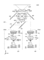
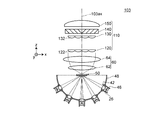
図1は、実施形態1に係るプロジェクター1000の光学系を示す平面図である。
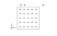
図2は、実施形態1における固体光源アレイ20をコリメーターレンズアレイ30側から見た図である。
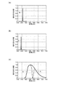
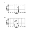
図3は、実施形態1における固体光源24の発光強度特性、第2固体光源224の発光強度特性及び蛍光体の発光強度特性を示すグラフである。図3(a)は固体光源24の発光強度特性を示すグラフであり、図3(b)は第2固体光源224の発光強度特性を示すグラフであり、図3(c)は蛍光層254が含有する蛍光体の発光強度特性を示すグラフである。発光強度特性とは、光源であれば電圧を印加したときに、蛍光体であれば励起光が入射したときに、どのような波長の光をどの位の強度で射出するのかという特性のことをいう。グラフの縦軸は相対発光強度を表し、発光強度が最も強い波長における発光強度を1としている。グラフの横軸は波長を表す。
図4は、実施形態1における透過型拡散手段50の入射面の拡大図である。
[Embodiment 1]
FIG. 1 is a plan view showing an optical system of a
FIG. 2 is a diagram of the solid-state
FIG. 3 is a graph showing the emission intensity characteristics of the solid-
FIG. 4 is an enlarged view of the incident surface of the transmissive diffusing
なお、各図面中において、符号Rは赤色光を示し、符号Gは緑色光を示し、符号Bは青色光を示す。
本明細書及び図面においては、本発明に直接関わらない構成要素(筐体等)については説明及び図示を省略する。
In each drawing, the symbol R indicates red light, the symbol G indicates green light, and the symbol B indicates blue light.
In the present specification and drawings, description and illustration of components (casing and the like) not directly related to the present invention are omitted.
実施形態1に係るプロジェクター1000は、図1に示すように、照明装置100と、第2照明装置200と、色分離導光光学系400と、光変調装置としての3つの液晶光変調装置500R,500G,500Bと、クロスダイクロイックプリズム600と、投写光学系700とを備える。
As shown in FIG. 1, the
照明装置100は、固体光源アレイ20と、コリメーターレンズアレイ30と、集光光学系40と、透過型拡散手段50と、コリメーター光学系60と、レンズインテグレーター光学系110とを備える。照明装置100は、照明光として青色光を射出する。
The
固体光源アレイ20は、図1及び図2に示すように、複数の固体光源を有する固体光源群であり、具体的には、基板22及び青色光を生成する25個の固体光源24を有する。固体光源アレイ20においては、25個の固体光源24は5行5列のマトリクス状に配置されている。
なお、本発明のプロジェクターにおいては、固体光源の数は複数(2個以上)であればよく、25個に限定されるものではない。また、固体光源群においては、各固体光源が離散的に配置されていてもよい。
As illustrated in FIGS. 1 and 2, the solid
In the projector of the present invention, the number of solid light sources may be plural (two or more), and is not limited to 25. In the solid light source group, the solid light sources may be arranged discretely.
基板22は、固体光源24を搭載する機能を有する。詳細な説明は省略するが、基板22は、固体光源24に対する電力の供給を仲介する機能や、固体光源24で発生する熱を放熱する機能等を併せて有する。
The
固体光源24は、色光としての青色光(発光強度のピーク:約460nm、図3(a)参照。)を生成する半導体レーザーからなる。当該半導体レーザーは、図2に示すように、長方形形状の発光領域を有し、発光領域の短辺方向に沿った拡がり角が前記発光領域の長辺方向に沿った拡がり角より大きくなるように構成されている。
The solid-
コリメーターレンズアレイ30は、図1に示すように、25個の固体光源24で生成された光をそれぞれ略平行化する25個のコリメーターレンズ32(端部の1つにのみ符号を図示)を有する。図示による説明は省略するが、25個のコリメーターレンズ32は、25個の固体光源24に対応するように、5行5列のマトリクス状に配置されている。詳しい説明は省略するが、コリメーターレンズ32は、入射面が双曲面で、かつ、射出面が平面の非球面平凸レンズからなる。
なお、各コリメーターレンズは離散的に配置されていてもよい。
As shown in FIG. 1, the
Each collimator lens may be arranged discretely.
集光光学系40は、コリメーターレンズアレイ30からの光(つまり、固体光源アレイ20(固体光源群)からの光)を所定の集光位置に集光する。詳しい説明は省略するが、集光光学系40は、入射面が平面で、かつ、射出面が双曲面の非球面平凸レンズからなる。
The condensing
透過型拡散手段50は、集光位置の近傍に位置し、集光光学系40からの光を拡散させながら通過させる。透過型拡散手段50は、図4に示すように、多数のマイクロレンズ52を有するマイクロレンズアレイ拡散板からなる。透過型拡散手段50においては、入射面側にマイクロレンズ52が形成されている。
マイクロレンズ52は、凸レンズからなる。多数のマイクロレンズ52は、隙間なく配置されており、そのピッチは、例えば、15μmである。なお、図1における透過型拡散手段50においては、マイクロレンズを実際よりも大きく表示している。後述する図5,7,9,10においても同様である。
マイクロレンズアレイ拡散板の表面には、ARコートが形成されている。また、マイクロレンズアレイ拡散板は、光学ガラスからなる。
The
The
An AR coat is formed on the surface of the microlens array diffusion plate. The microlens array diffuser plate is made of optical glass.
図示による説明は省略するが、照明装置100は、透過型拡散手段50を通過した光が、レンズインテグレーター光学系110における有効領域の約85%の面積に入射するように構成されている。
また、照明装置100は、集光光学系40からの光が、透過型拡散手段50上における一辺0.8mmの正方形の領域内に入射するように構成されている。
Although description by illustration is abbreviate | omitted, the illuminating
The illuminating
コリメーター光学系60は、集光光学系40とは集光位置を挟んで配置され、透過型拡散手段50からの光(元をたどれば集光光学系40からの光)を略平行化する。コリメーター光学系60は、図1に示すように、第1レンズ62及び第2レンズ64を備える。第1レンズ62及び第2レンズ64は、両凸レンズからなる。なお、第1レンズ及び第2レンズの形状は、上記形状に限定されるものではなく、要するに、コリメーター光学系が透過型拡散手段からの光を略平行化するようになる形状であればよい。また、コリメーター光学系を構成するレンズの枚数は、1枚であってもよく、3枚以上であってもよい。
The collimator
照明装置100においては、固体光源アレイ20、コリメーターレンズアレイ30、集光光学系40、透過型拡散手段50及びコリメーター光学系60で青色光用の光源装置を構成する。
In the
レンズインテグレーター光学系110は、コリメーター光学系60からの光の面内光強度分布を均一化する。レンズインテグレーター光学系110は、第1レンズアレイ120と、第2レンズアレイ130と、偏光変換素子140と、重畳レンズ150とを備える。
The lens integrator
第1レンズアレイ120は、図1に示すように、コリメーター光学系60からの光を複数の部分光束に分割するための複数の第1小レンズ122を有する。第1レンズアレイ120は、コリメーター光学系60からの光を複数の部分光束に分割する光束分割光学素子としての機能を有し、複数の第1小レンズ122が照明光軸100axと直交する面内に複数行・複数列のマトリクス状に配列された構成を有する。図示による説明は省略するが、第1小レンズ122の外形形状は、各液晶光変調装置における画像形成領域の外形形状に関して略相似形である。
As shown in FIG. 1, the
第2レンズアレイ130は、第1レンズアレイ120における複数の第1小レンズ122に対応する複数の第2小レンズ132を有する。第2レンズアレイ130は、重畳レンズ150とともに、第1レンズアレイ120の各第1小レンズ122の像を液晶光変調装置500Bの画像形成領域近傍に結像させる機能を有する。第2レンズアレイ130は、複数の第2小レンズ132が照明光軸100axに直交する面内に複数行・複数列のマトリクス状に配列された構成を有する。
The
偏光変換素子140は、第1レンズアレイ120により分割された各部分光束の偏光方向を、偏光方向の揃った略1種類の直線偏光からなる光として射出する偏光変換素子である。
偏光変換素子140は、コリメーター光学系60からの光に含まれる偏光成分のうち一方の直線偏光成分をそのまま透過し、他方の直線偏光成分を照明光軸100axに垂直な方向に反射する偏光分離層と、偏光分離層で反射された他方の直線偏光成分を照明光軸100axに平行な方向に反射する反射層と、反射層で反射された他方の直線偏光成分を一方の直線偏光成分に変換するλ/2板とを有している。レンズインテグレーター光学系110は、偏光変換素子140を備えることにより、偏光方向が揃った光を射出する。
The
The
重畳レンズ150は、各部分光束を集光して液晶光変調装置500Bの画像形成領域近傍に重畳させるための光学素子である。重畳レンズ150の光軸と照明光軸100axとが略一致するように、重畳レンズ150が配置されている。なお、重畳レンズは、複数のレンズを組み合わせた複合レンズで構成されていてもよい。
The superimposing
第2照明装置200は、第2固体光源アレイ220と、コリメーターレンズアレイ230と、集光光学系240と、蛍光生成部250と、コリメーター光学系260と、レンズインテグレーター光学系310とを備える。第2照明装置200は、色光として赤色光及び緑色光を含む光を射出する。
The
第2固体光源アレイ220は、基板222(符号を図示せず。)及び励起光としての青色光を生成する25個の第2固体光源224を有する。第2固体光源アレイは、第2固体光源224以外については固体光源アレイ20と基本的に同様の構成を有する。
第2固体光源224は、励起光として青色光(発光強度のピーク:約440nm、図3(b)参照。)を生成すること以外については、固体光源24と基本的に同様の構成を有する。なお、固体光源と第2固体光源とで生成する青色光の波長を同じにしてもよい。
The second solid
The second solid-
コリメーターレンズアレイ230はコリメーターレンズアレイ30と、集光光学系240は集光光学系40と、それぞれ基本的に同様の構成を有するため、説明を省略する。
Since the
蛍光生成部250は、透明部材252及び蛍光層254を有する。
透明部材252は、蛍光層254を担持する部材であり、例えば、石英ガラス又は光学ガラスからなる。
蛍光層254の集光光学系240側には、集光光学系240からの青色光を通過させ蛍光を反射する層(いわゆるダイクロイックコート)が形成されていてもよい。
The
The
A layer (so-called dichroic coat) that allows blue light from the condensing
蛍光層254は、YAG系蛍光体である(Y,Gd)3(Al,Ga)5O12:Ceを含有する層からなる。なお、蛍光層は、他のYAG系蛍光体を含有する層からなるものであってもよいし、YAG蛍光体以外の蛍光体(例えばシリケート系蛍光体やTAG系蛍光体)を含有する層からなるものであってもよい。また、励起光を赤色光に変換する蛍光体(例えばCaAlSiN3赤色蛍光体)と、励起光を緑色に変換する蛍光体(例えばβサイアロン緑色蛍光体)との混合物を含有する層からなるものであってもよい。
蛍光層254は、集光光学系240からの青色光から赤色光(発光強度のピーク:約610nm)及び緑色光(発光強度のピーク:約550nm)を含む蛍光を生成する(図3(c)参照。)。
The
The
コリメーター光学系260はコリメーター光学系60と基本的に同様の構成を有するため、説明を省略する。
第2照明装置200においては、固体光源アレイ220、コリメーターレンズアレイ230、集光光学系240、蛍光生成部250及びコリメーター光学系260で赤色光及び緑色光用の光源装置を構成する。
Since the collimator
In the
レンズインテグレーター光学系310はレンズインテグレーター光学系110と基本的に同様の構成を有するため、説明を省略する。
Since the lens integrator
色分離導光光学系400は、ダイクロイックミラー410、反射ミラー420,430,440を備える。色分離導光光学系400は、照明装置100からの光を液晶光変調装置500Bに導光する機能と、第2照明装置200からの光を赤色光及び緑色光に分離し、それぞれの色光を照明対象となる液晶光変調装置500R,500Gに導光する機能とを有する。
色分離導光光学系400と、各液晶光変調装置との間には、集光レンズ450R,450G,450Bが配置されている。
The color separation light guide
Condensing
ダイクロイックミラー410は、基板上に、緑色光を反射して、赤色光を通過させる波長選択透過膜が形成されたミラーである。
反射ミラー420は、緑色光成分を反射する反射ミラーである。
反射ミラー430は、赤色光成分を反射する反射ミラーである。
反射ミラー440は、青色光成分を反射する反射ミラーである。
The
The
The
The
第2照明装置200からの光は、ダイクロイックミラー410において赤色光及び緑色光に分離される。
ダイクロイックミラー410を通過した赤色光は、反射ミラー430で反射され、集光レンズ450Rを通過して赤色光用の液晶光変調装置500Rの画像形成領域に入射する。
ダイクロイックミラー410で反射された緑色光は、反射ミラー420でさらに反射され、集光レンズ450Gを通過して緑色光用の液晶光変調装置500Gの画像形成領域に入射する。
照明装置100からの光は、反射ミラー440で反射され、集光レンズ450Bを通過して青色光用の液晶光変調装置500Bの画像形成領域に入射する。
Light from the
The red light that has passed through the
The green light reflected by the
The light from the
各液晶光変調装置は、入射された色光を画像情報に応じて変調してカラー画像を形成するものであり、液晶光変調装置500R,500Gは第2照明装置200の照明対象となり、液晶光変調装置500Bは照明装置100の照明対象となる。なお、図示を省略したが、各集光レンズと各液晶光変調装置との間には、それぞれ入射側偏光板が介在配置され、各液晶光変調装置とクロスダイクロイックプリズム600との間には、それぞれ射出側偏光板が介在配置される。これら入射側偏光板、各液晶光変調装置及び射出側偏光板によって、入射された各色光の光変調が行われる。
各液晶光変調装置は、一対の透明なガラス基板に電気光学物質である液晶を密閉封入した光変調領域を有する透過型の液晶光変調装置であり、例えば、ポリシリコンTFTをスイッチング素子として、与えられた画像信号に応じて、入射側偏光板から射出された1種類の直線偏光の偏光方向を変調する。
Each liquid crystal light modulation device modulates incident color light in accordance with image information to form a color image. The liquid crystal
Each liquid crystal light modulation device is a transmission type liquid crystal light modulation device having a light modulation region in which a liquid crystal as an electro-optical material is hermetically sealed in a pair of transparent glass substrates. For example, a polysilicon TFT is used as a switching element. In accordance with the received image signal, the polarization direction of one kind of linearly polarized light emitted from the incident side polarizing plate is modulated.
クロスダイクロイックプリズム600は、射出側偏光板から射出された色光毎に変調された光学像を合成してカラー画像を形成する光学素子である。このクロスダイクロイックプリズム600は、4つの直角プリズムを貼り合わせた平面視略正方形状をなし、直角プリズム同士を貼り合わせた略X字状の界面には、誘電体多層膜が形成されている。略X字状の一方の界面に形成された誘電体多層膜は、赤色光を反射するものであり、他方の界面に形成された誘電体多層膜は、青色光を反射するものである。これらの誘電体多層膜によって赤色光及び青色光は曲折され、緑色光の進行方向と揃えられることにより、3つの色光が合成される。
The cross
クロスダイクロイックプリズム600から射出されたカラー画像は、投写光学系700によって拡大投写され、スクリーンSCR上で画像を形成する。
The color image emitted from the cross
次に、実施形態1に係る照明装置100及びプロジェクター1000の効果を説明する。
Next, effects of the
実施形態1に係る照明装置100は、複数の固体光源24を有する固体光源群(固体光源アレイ20)と、集光光学系40からの光を拡散させながら通過させる透過型拡散手段50とを備えるため、斑状の光を拡散した上でレンズインテグレーター光学系110に入射させることが可能となり、高輝度の照明光を得ることと、高い光利用効率をもって明るさむらの少ない照明光を得ることとを両立させることが可能な照明装置となる。
The
また、実施形態1に係る照明装置100によれば、透過型拡散手段50は、マイクロレンズアレイ拡散板からなるため、透過型拡散手段を用いることに伴う光のロスを低減して光の利用効率を一層高くすることが可能となる。
Further, according to the
また、実施形態1に係る照明装置100によれば、マイクロレンズアレイ拡散板にはARコートが形成されているため、後方散乱を一層抑制して光の利用効率をより一層高くすることが可能となる。
Moreover, according to the illuminating
また、実施形態1に係る照明装置100によれば、マイクロレンズアレイ拡散板は無機材料(光学ガラス)からなるため、透過型拡散手段50の耐熱性を高くして照明装置の信頼性を高くすることが可能となる。
Moreover, according to the illuminating
また、実施形態1に係る照明装置100によれば、透過型拡散手段50を通過した光が、レンズインテグレーター光学系110における有効領域の50%以上の面積に入射するように構成されているため、より一層均一な照明光を得ることが可能となる。
Moreover, according to the illuminating
また、実施形態1に係る照明装置100によれば、固体光源24は、半導体レーザーからなるため、照明装置の小型化及び高出力化が可能となり、また、複数の固体光源24を高密度で集積することにより、照明装置のさらなる高出力化が可能となる。
Moreover, according to the illuminating
また、実施形態1に係る照明装置100によれば、集光光学系40からの光が、透過型拡散手段50上における一辺1mmの正方形の領域内に入射するため、集光光学系40からの光が透過型拡散手段50に入射する面積が十分に小さいものとなり、複数の固体光源24を用いることに起因する照明装置の光利用効率の低下を抑制することが可能となる。
Moreover, according to the illuminating
実施形態1に係るプロジェクター1000によれば、より一層の高輝度化と、高い光利用効率をもって明るさむらの少ない照明光を得ることとの両立が可能な実施形態1に係る照明装置100を備えるため、高輝度で明るさむらの少ない投写画像を投写することが可能となる。
The
また、実施形態1に係るプロジェクター1000によれば、励起光(青色光)を生成する第2固体光源224と、第2固体光源224で生成された励起光から蛍光(赤色光及び緑色光)を生成する蛍光層254とを備える第2照明装置200を備え、光変調装置(液晶光変調装置500R,500G)は、第2照明装置200からの光について画像情報に応じて変調するため、所望の色光を用いて高輝度カラー画像を投写することが可能となる。
Further, according to the
[実施形態2]
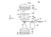
図5は、実施形態2に係る照明装置101の光学系を示す平面図である。
図6は、実施形態2における回転板70を駆動装置80側から見た図である。図6において、符号Bで示す正方形は、一辺が0.8mmの正方形であり、集光光学系40からの光は、当該正方形に包含される大きさで透過型拡散手段54に入射する。後述する図11〜図13においても同様であり、その際には付された符号が入射する色光の種類を示している。
[Embodiment 2]
FIG. 5 is a plan view showing an optical system of the
FIG. 6 is a view of the
実施形態2に係る照明装置101は、基本的には実施形態1に係る照明装置100と同様の構成を有するが、回転板及び駆動装置を備えることが実施形態1に係る照明装置100の場合とは異なる。すなわち、実施形態2に係る照明装置101は、図5及び図6に示すように、集光位置の近傍に位置し、駆動装置80により所定の回転軸70axの周りを回転動作可能な回転板70をさらに備え、透過型拡散手段54は、回転板70における少なくとも集光光学系40からの光が通過する位置に配置されている。
The
回転板70は、回転基板72と透過型拡散手段54とを有する。
回転基板72は、透過型拡散手段54を支持するとともに、中心部で駆動装置80に接続されている。
透過型拡散手段54は、基本的には実施形態1における透過型拡散手段50と同様の構成を有するが、図6に示すように、回転板70中にあり、リング状の形状を有する。このため、回転板70の回転に関わらず、集光光学系40からの光は透過型拡散手段54に入射する。
駆動装置80は、図5に示すように、回転板70の、集光光学系40からの入射光が入射する側に配置されている。駆動装置80は、略円筒形の形状からなり、駆動装置80における回転部(符号を図示せず。)が、回転基板72の回転中心に直接取り付けられている。駆動装置80は、例えばモーターからなる。
なお、駆動装置における回転部は、ベルト等の介在手段を介して回転板に取り付けられていてもよい。
The rotating
The rotating
The
As shown in FIG. 5, the driving
In addition, the rotation part in a drive device may be attached to the rotating plate via interposition means, such as a belt.
上記のように、実施形態2に係る照明装置101は、回転板及び駆動装置を備えることが実施形態1に係る照明装置100の場合とは異なるが、複数の固体光源24を有する固体光源群(固体光源アレイ20)と、集光光学系40からの光を拡散させながら通過させる透過型拡散手段54とを備えるため、斑状の光を拡散した上でレンズインテグレーター光学系110に入射させることが可能となり、実施形態1に係る照明装置100と同様に、高輝度の照明光を得ることと、高い光利用効率をもって明るさむらの少ない照明光を得ることとを両立させることが可能な照明装置となる。
As described above, the illuminating
また、実施形態2に係る照明装置101によれば、回転板70を備え、透過型拡散手段54は、回転板70における少なくとも集光光学系40からの光が通過する位置に配置されているため、光の入射位置が、透過型拡散手段54の入射面上を広い範囲で移動するようになり、透過型拡散手段54にかかる熱的負荷を低減し、透過型拡散手段54の劣化や焼損を抑制することが可能となる。
Further, according to the
また、実施形態2に係る照明装置101によれば、照明光におけるスペックルノイズを低減することが可能となる。
Moreover, according to the illuminating
なお、実施形態2に係る照明装置101は、回転板及び駆動装置を備える以外は、実施形態1に係る照明装置100と同様の構成を有するため、実施形態1に係る照明装置100が有する効果のうち該当する効果をそのまま有する。
In addition, since the illuminating
[実施形態3]
図7は、実施形態3に係るプロジェクター1004の光学系を示す平面図である。
図8は、実施形態3における固体光源24Rの発光強度特性及び蛍光体の発光強度特性を示すグラフである。図8(a)は固体光源24Rの発光強度特性を示すグラフであり、図8(b)は蛍光層256が含有する蛍光体の発光強度特性を示すグラフである。
[Embodiment 3]
FIG. 7 is a plan view showing an optical system of the
FIG. 8 is a graph showing the emission intensity characteristics of the solid-
実施形態3に係る照明装置102は、基本的には実施形態1に係る照明装置100と同様の構成を有するが、赤色光用の光源装置、緑色光用の光源装置及びクロスダイクロイックプリズムを備えることが実施形態1に係る照明装置100の場合とは異なる。また、それに伴って、実施形態3に係るプロジェクター1004においては、第2照明装置を備えず、また、色分離導光光学系の構成が異なる。以下、照明装置102及び色分離導光光学系402について説明する。
The
青色光用の光源装置を構成する固体光源アレイ20、コリメーターレンズアレイ30、集光光学系40、透過型拡散手段50及びコリメーター光学系60は、実施形態1における固体光源アレイ20、コリメーターレンズアレイ30、集光光学系40、透過型拡散手段50及びコリメーター光学系60とそれぞれ同様の構成を有するため、説明を省略する。
The solid-state
赤色光用の光源装置を構成する固体光源アレイ20R、コリメーターレンズアレイ30R、集光光学系40R、透過型拡散手段50R及びコリメーター光学系60Rは、固体光源の構成以外については固体光源アレイ20、コリメーターレンズアレイ30、集光光学系40、透過型拡散手段50及びコリメーター光学系60とそれぞれ基本的に同様の構成を有する。
固体光源24Rは、色光として赤色光(発光強度のピーク:約640nm、図8(a)参照。)を生成すること以外については、固体光源24と基本的に同様の構成を有する。
The solid
The solid
緑色光用の光源装置を構成する固体光源アレイ220、コリメーターレンズアレイ230、集光光学系240、蛍光生成部250及びコリメーター光学系260は、蛍光生成部の構成以外については実施形態1における第2照明装置200の固体光源アレイ220、コリメーターレンズアレイ230、集光光学系240、蛍光生成部250及びコリメーター光学系260とそれぞれ基本的に同様の構成を有する。
蛍光生成部251は、集光光学系40からの青色光から緑色光(発光強度のピーク:約570nm、図8(b)参照。)を含む蛍光を生成する蛍光層256を有すること以外については実施形態1における蛍光生成部254と基本的に同様の構成を有する。
蛍光層256は、青色光を緑色に変換する蛍光体(例えばβサイアロン緑色蛍光体)を含有する層からなる。
The solid-state
The
The
クロスダイクロイックプリズム90は、各色光用の光源装置からの光を合成する光学素子であり、クロスダイクロイックプリズム600と基本的に同様の構成を有する。
The cross
色分離導光光学系402は、基本的には実施形態1における色分離導光光学系400と同様の構成を有するが、反射ミラー420の代わりにダイクロイックミラー422を備え、反射ミラー442をさらに備える。
ダイクロイックミラー422は緑色光を反射し、青色光を通過させるミラーである。
反射ミラー442は、青色光を反射する反射ミラーである。
なお、ダイクロイックミラー422から反射ミラー440までの光路中においては、光の発散等による光の利用効率の低下を防止するためのリレーレンズが設けられていてもよい。
The color separation light guide
The
The
In the optical path from the
上記のように、実施形態3に係る照明装置102は、赤色光用の光源装置、緑色光用の光源装置及びクロスダイクロイックプリズムを備えることが実施形態1に係る照明装置100の場合とは異なるが、複数の固体光源24,24Rを有する固体光源群(固体光源アレイ20,20R)と、集光光学系40,40Rからの光を拡散させながら通過させる透過型拡散手段50,50Rとを備えるため、斑状の光を拡散した上でレンズインテグレーター光学系110,110Rに入射させることが可能となり、実施形態1に係る照明装置100と同様に、高輝度の照明光を得ることと、高い光利用効率をもって明るさむらの少ない照明光を得ることとを両立させることが可能な照明装置となる。
As described above, the
なお、実施形態3に係る照明装置102は、赤色光用の光源装置、緑色光用の光源装置及びクロスダイクロイックプリズムを備える以外は、実施形態1に係る照明装置100と同様の構成を有するため、実施形態1に係る照明装置100が有する効果をそのまま有する。
The
上記のように実施形態3に係るプロジェクター1004によれば、第2照明装置を備えないことと、照明装置及び色分離導光光学系の構成とが実施形態1に係るプロジェクター1000の場合とは異なるが、より一層の高輝度化と、高い光利用効率をもって明るさむらの少ない照明光を得ることとの両立が可能な実施形態3に係る照明装置102を備えるため、実施形態1に係るプロジェクター1000と同様に、高輝度で明るさむらの少ない投写画像を投写することが可能となる。
As described above, the
また、上記のように実施形態3に係るプロジェクター1004によれば、照明装置102は、励起光(青色光)を生成する第2固体光源224と、第2固体光源224で生成された励起光から蛍光(緑色光)を生成する蛍光層246とを備え、また、固体光源群として、それぞれ生成する色光が異なる複数の固体光源群(固体光源アレイ20及び固体光源アレイ20R)を備えるため、所望の色光を用いて高輝度カラー画像を投写することが可能となる。
Further, as described above, according to the
以上、本発明を上記の実施形態に基づいて説明したが、本発明は上記の実施形態に限定されるものではない。その趣旨を逸脱しない範囲において種々の様態において実施することが可能であり、例えば、次のような変形も可能である。 As mentioned above, although this invention was demonstrated based on said embodiment, this invention is not limited to said embodiment. The present invention can be carried out in various modes without departing from the spirit thereof, and for example, the following modifications are possible.
(1)上記各実施形態においては、固体光源群及び集光光学系として、1つの固体光源アレイ及び1つの集光光学系(集光レンズ)を用いたが、本発明はこれに限定されるものではない。例えば、図9に示すように、固体光源群及び集光光学系として、複数の固体光源及び複数の集光光学系を用いてもよい。図9は、変形例1に係る照明装置103の光学系を示す平面図である。照明装置103は、図9に示すように、固体光源群及び集光光学系として、複数の固体光源26(符号は右端の1つにのみ表示)及び複数の集光光学系42(符号は右端の1つにのみ表示)を備える。なお、固体光源26と集光光学系42とはそれぞれ1対ずつ、筒状の保持部46(符号は右端の1つにのみ表示)によって固定されている。また、保持部46は半球状の固定具48に固定されている。上記のように、固体光源群及び集光光学系として、複数の固体光源及び複数の集光光学系を用いてもよい。
(1) In each of the above embodiments, one solid light source array and one condensing optical system (condensing lens) are used as the solid light source group and the condensing optical system, but the present invention is limited to this. It is not a thing. For example, as shown in FIG. 9, a plurality of solid light sources and a plurality of condensing optical systems may be used as the solid light source group and the condensing optical system. FIG. 9 is a plan view showing an optical system of the
(2)上記各実施形態においては、1つの集光光学系に対して1つの透過型拡散手段を用いたが、本発明はこれに限定されるものではない。例えば、図10及び図11に示すように、2つの集光光学系に対して1つの透過型拡散手段を用いてもよい。図10は、変形例2に係るプロジェクター1008の光学系を示す平面図である。図11は、変形例2における回転板71を駆動装置側から見た図である。変形例2に係る照明装置104における透過型拡散手段55は、図10及び図11に示すように、集光光学系40からの青色光を拡散させながら通過させるとともに、集光光学系40Rからの赤色光も拡散させながら通過させる。なお、変形例2に係るプロジェクター1008においては、緑色光を射出する第2照明装置202(点線で図示)は照明装置104よりも紙面奥方向に配置されており、第2照明装置202からの緑色光は、反射ミラー群424により光路を調整された上で集光レンズ450に入射する。上記のように、2つの集光光学系に対して1つの透過型拡散手段を用いてもよい。
(2) In each of the above embodiments, one transmission type diffusing unit is used for one condensing optical system, but the present invention is not limited to this. For example, as shown in FIGS. 10 and 11, one transmission type diffusing unit may be used for two condensing optical systems. FIG. 10 is a plan view showing an optical system of a
(3)上記各実施形態においては、蛍光層により生成した緑色光を用いたが、本発明はこれに限定されるものではない。固体光源により生成した緑色光を用いてもよい。図12は、変形例3における回転板76を駆動装置側から見た図である。この場合においては、図12に示すように、3つの集光光学系に対して1つの透過型拡散手段を用いてもよい。また、3つ以上の集光光学系に対して1つの透過型拡散手段を用いてもよい。
(3) In each of the above embodiments, the green light generated by the fluorescent layer is used, but the present invention is not limited to this. Green light generated by a solid light source may be used. FIG. 12 is a view of the
(4)上記実施形態2においては、透過型拡散手段54を有する回転板70を用いたが、本発明はこれに限定されるものではない。図13は、変形例4における回転板78を駆動装置側から見た図である。符号258で示すのは、青色光から緑色光を生成する蛍光生成部である。例えば、図13に示すように、透過型拡散手段の他に蛍光生成部を有する回転板を用いてもよい。
(4) In the second embodiment, the rotating
(5)上記各実施形態においては、凸レンズからなるマイクロレンズを有する透過型拡散手段(マイクロレンズアレイ拡散板)を用いたが、本発明はこれに限定されるものではない。図14は、変形例5における透過型拡散手段58(図示せず。)の入射面の拡大図である。符号53で示すのは、凹レンズからなるマイクロレンズである。図14に示すように、凹レンズからなるマイクロレンズを有する透過型拡散手段(マイクロレンズアレイ拡散板)を用いてもよい。
(5) In each of the above embodiments, the transmission type diffusing means (microlens array diffusion plate) having a microlens made of a convex lens is used, but the present invention is not limited to this. FIG. 14 is an enlarged view of an incident surface of a transmissive diffusing unit 58 (not shown) in Modification 5.
(6)上記各実施形態においては、マイクロレンズアレイ拡散板からなる透過型拡散手段を用いたが、本発明はこれに限定されるものではない。例えば、ホログラフィック拡散板からなる透過型拡散手段を用いてもよい。このような構成とすることによっても、透過型拡散手段を用いることに伴う光のロスを低減して光の利用効率を一層高くすることが可能となる。 (6) In each of the above-described embodiments, the transmission type diffusing means including the microlens array diffusion plate is used. However, the present invention is not limited to this. For example, a transmission type diffusing unit made of a holographic diffusion plate may be used. Even with such a configuration, it is possible to further reduce the light loss associated with the use of the transmissive diffusing means and further increase the light utilization efficiency.
(7)上記各実施形態においては、入射面側にマイクロレンズが形成されているマイクロレンズアレイ拡散板を用いたが、本発明はこれに限定されるものではない。射出面側にマイクロレンズが形成されているマイクロレンズアレイ拡散板や、入射面と射出面との両方にマイクロレンズが形成されているマイクロレンズアレイ拡散板を用いてもよい。 (7) In each of the above embodiments, the microlens array diffuser plate in which the microlens is formed on the incident surface side is used, but the present invention is not limited to this. A microlens array diffuser plate in which microlenses are formed on the exit surface side, or a microlens array diffuser plate in which microlenses are formed on both the entrance surface and the exit surface may be used.
(8)上記各実施形態においては、入射面が双曲面で、かつ、射出面が平面の非球面平凸レンズからなるコリメーターレンズを用いたが、本発明はこれに限定されるものではない。例えば、入射面が平面で、かつ、射出面が楕円面の非球面平凸レンズからなるコリメーターレンズを用いてもよい。また、1枚のレンズからなるコリメーターレンズの代わりに、複数のレンズからなるコリメーターレンズを用いてもよい。要するに、固体光源又は第2固体光源に対応して設けられ、対応する固体光源又は第2固体光源で生成された光を略平行化することが可能なコリメーターレンズを用いればよい。 (8) In each of the above embodiments, a collimator lens made up of an aspheric plano-convex lens having a hyperboloidal entrance surface and a flat exit surface is used, but the present invention is not limited to this. For example, a collimator lens made of an aspheric plano-convex lens having a flat entrance surface and an elliptical exit surface may be used. Further, a collimator lens composed of a plurality of lenses may be used instead of the collimator lens composed of a single lens. In short, a collimator lens provided corresponding to the solid light source or the second solid light source and capable of substantially collimating the light generated by the corresponding solid light source or the second solid light source may be used.
(9)上記各実施形態においては、入射面が平面で、かつ、射出面が双曲面の非球面平凸レンズからなる集光光学系を用いたが、本発明はこれに限定されるものではない。例えば、入射面が楕円面で、かつ、射出面が平面の非球面平凸レンズからなる集光光学系を用いてもよい。また、1枚のレンズからなる集光光学系の代わりに、複数のレンズからなる集光光学系を用いてもよい。要するに、コリメーターレンズアレイからの光を所定の集光位置に集光することが可能な集光光学系を用いればよい。 (9) In each of the above-described embodiments, the condensing optical system including an aspherical planoconvex lens having a flat entrance surface and a hyperboloidal exit surface is used. However, the present invention is not limited to this. . For example, a condensing optical system composed of an aspheric plano-convex lens having an elliptical entrance surface and a flat exit surface may be used. A condensing optical system composed of a plurality of lenses may be used instead of the condensing optical system composed of a single lens. In short, a condensing optical system capable of condensing the light from the collimator lens array at a predetermined condensing position may be used.
(10)上記各実施形態においては、半導体レーザーからなる固体光源及び第2固体光源を用いたが、本発明はこれに限定されるものではない。例えば、発光ダイオードからなる固体光源及び第2固体光源を用いてもよい。 (10) In each of the above embodiments, the solid light source and the second solid light source made of a semiconductor laser are used, but the present invention is not limited to this. For example, you may use the solid light source and 2nd solid light source which consist of a light emitting diode.
(11)上記各実施形態においては、透過型のプロジェクターを用いたが、本発明はこれに限定されるものではない。例えば、反射型のプロジェクターを用いてもよい。ここで、「透過型」とは、透過型の液晶光変調装置等のように光変調手段としての光変調装置が光を透過するタイプであることを意味しており、「反射型」とは、反射型の液晶光変調装置等のように光変調手段としての光変調装置が光を反射するタイプであることを意味している。反射型のプロジェクターにこの発明を適用した場合にも、透過型のプロジェクターと同様の効果を得ることができる。 (11) In each of the above embodiments, a transmissive projector is used, but the present invention is not limited to this. For example, a reflective projector may be used. Here, “transmission type” means that a light modulation device as a light modulation means such as a transmission type liquid crystal light modulation device or the like is a type that transmits light, and “reflection type” means This means that the light modulation device as the light modulation means, such as a reflective liquid crystal light modulation device, is a type that reflects light. Even when the present invention is applied to a reflective projector, the same effect as that of a transmissive projector can be obtained.
(12)上記実施形態1においては、3つの光変調装置を用いたプロジェクターを例示して説明したが、本発明はこれに限定されるものではない。1つ、2つ又は4つ以上の光変調装置を用いたプロジェクターにも適用可能である。 (12) In the first embodiment, the projector using three light modulation devices has been described as an example. However, the present invention is not limited to this. The present invention is also applicable to a projector using one, two, or four or more light modulation devices.
(13)本発明は、投写画像を観察する側から投写するフロント投写型プロジェクターに適用する場合にも、投写画像を観察する側とは反対の側から投写するリア投写型プロジェクターに適用する場合にも可能である。 (13) The present invention can be applied to a rear projection type projector that projects from a side opposite to the side that observes the projected image, even when applied to a front projection type projector that projects from the side that observes the projected image. Is also possible.
(14)上記各実施形態においては、プロジェクターの光変調装置として液晶光変調装置を用いたが、本発明はこれに限定されるものではない。光変調装置としては、一般に、画像情報に応じて入射光を変調するものであればよく、マイクロミラー型光変調装置等を用いてもよい。マイクロミラー型光変調装置としては、例えば、DMD(デジタルマイクロミラーデバイス)(TI社の商標)を用いることができる。 (14) In each of the above embodiments, the liquid crystal light modulation device is used as the light modulation device of the projector, but the present invention is not limited to this. In general, the light modulation device only needs to modulate incident light according to image information, and a micromirror light modulation device or the like may be used. For example, a DMD (digital micromirror device) (trademark of TI) can be used as the micromirror light modulator.
(15)上記各実施形態においては、本発明の照明装置をプロジェクターに適用した例について説明したが、本発明はこれに限定されるものではない。例えば、本発明の照明装置を他の光学機器(例えば、光ディスク装置、自動車のヘッドランプ、照明機器等。)に適用することもできる。 (15) In each of the above embodiments, the example in which the illumination device of the present invention is applied to a projector has been described, but the present invention is not limited to this. For example, the lighting device of the present invention can be applied to other optical devices (for example, an optical disk device, a car headlamp, a lighting device, etc.).
20,20R…固体光源アレイ、22…基板、24,24R,26…固体光源、30,30R,230…コリメーターレンズアレイ、32,32R,232…コリメーターレンズ、40,40R,42,240…集光光学系、46…保持部、48…固定具、50,50R,54,55…透過型拡散手段、52,53…マイクロレンズ、60,60R,260…コリメーター光学系、62,62R,262…第1レンズ、64,64R,264…第2レンズ、70,71,76,78…回転板、70ax,71ax…回転軸、72,73,77…回転基板、80…駆動装置、90,600…クロスダイクロイックプリズム、100,101,102,103,104…照明装置、100ax,101ax,102ax,103ax,104ax…照明光軸、110,110R,310…レンズインテグレーター光学系、120,120R,320…第1レンズアレイ、122,122R,322…第1小レンズ、130,130R,330…第2レンズアレイ、132,132R,332…第2小レンズ、140,140R,340…偏光変換素子、150,150R,350…重畳レンズ、200,202…第2照明装置、200ax…第2照明光軸、220…第2固体光源アレイ、224…第2固体光源、250,251,258…蛍光生成部、252…透明部材、254,256…蛍光層、400…色分離導光光学系、410,422…ダイクロイックミラー、420,430,440,442…反射ミラー、424…反射ミラー群、450R,450G,450B…集光レンズ、500R,500G,500B…液晶光変調装置、700…投写光学系、1000,1004,1008…プロジェクター、SCR…スクリーン 20, 20R ... solid light source array, 22 ... substrate, 24, 24R, 26 ... solid light source, 30, 30R, 230 ... collimator lens array, 32, 32R, 232 ... collimator lens, 40, 40R, 42, 240 ... Condensing optical system, 46 ... holding portion, 48 ... fixture, 50, 50R, 54, 55 ... transmissive diffusing means, 52, 53 ... micro lens, 60, 60R, 260 ... collimator optical system, 62, 62R, 262 ... 1st lens, 64, 64R, 264 ... 2nd lens, 70, 71, 76, 78 ... Rotating plate, 70ax, 71ax ... Rotating shaft, 72, 73, 77 ... Rotating substrate, 80 ... Drive device, 90, 600: Cross dichroic prism, 100, 101, 102, 103, 104 ... Illumination device, 100ax, 101ax, 102ax, 103ax, 104ax Illumination optical axis, 110, 110R, 310 ... lens integrator optical system, 120, 120R, 320 ... first lens array, 122, 122R, 322 ... first small lens, 130, 130R, 330 ... second lens array, 132, 132R, 332 ... second small lens, 140,140R, 340 ... polarization conversion element, 150,150R, 350 ... superimposed lens, 200,202 ... second illumination device, 200ax ... second illumination optical axis, 220 ... second solid Light source array, 224, second solid light source, 250, 251, 258, fluorescence generation unit, 252, transparent member, 254, 256, fluorescent layer, 400, color separation light guide optical system, 410, 422, dichroic mirror, 420, 430, 440, 442 ... reflective mirror, 424 ... reflective mirror group, 450R, 450G, 450B ... condensing lens , 500R, 500G, 500B ... liquid crystal light modulation device, 700 ... projection optical system, 1000,1004,1008 ... projector, SCR ... screen
Claims (12)
前記固体光源群からの光を所定の集光位置に集光する集光光学系と、
前記集光光学系から入射した斑状の光を拡散させながら通過させる透過型拡散手段と、
前記透過型拡散手段からの光が入射するコリメーター光学系と、
前記コリメーター光学系からの光が入射するレンズインテグレーター光学系と、を備えることを特徴とする照明装置。 A solid light source group having a plurality of solid light sources;
A condensing optical system for condensing the light from the solid light source group at a predetermined condensing position ;
Transmissive diffusing means for allowing the speckled light incident from the condensing optical system to pass while diffusing; and
A collimator optical system on which light from the transmission type diffusing means is incident;
And a lens integrator optical system into which light from the collimator optical system is incident.
前記透過型拡散手段は、前記集光位置の近傍に配置されていることを特徴とする照明装置。The transmissive diffusing unit is disposed in the vicinity of the light collecting position.
前記透過型拡散手段は、マイクロレンズアレイ拡散板からなることを特徴とする照明装置。 The lighting device according to claim 1 or 2 ,
The transmissive diffusing unit comprises a microlens array diffusing plate.
前記透過型拡散手段は、ホログラフィック拡散板からなることを特徴とする照明装置。 The lighting device according to claim 1 or 2 ,
The transmissive diffusing unit comprises a holographic diffusion plate.
前記透過型拡散手段を通過した光が、前記レンズインテグレーター光学系における有効領域の50%以上の面積に入射するように構成されていることを特徴とする照明装置。 In the illuminating device in any one of Claims 1-4 ,
The illumination device, wherein the light that has passed through the transmission type diffusing unit is incident on an area of 50% or more of an effective area in the lens integrator optical system.
前記固体光源は、半導体レーザーからなることを特徴とする照明装置。 In the illuminating device in any one of Claims 1-5 ,
The illumination device according to claim 1, wherein the solid-state light source is made of a semiconductor laser.
駆動装置により所定の回転軸の周りを回転動作可能な回転板をさらに備え、
前記透過型拡散手段は、前記回転板における少なくとも前記集光光学系からの
光が通過する位置に配置されていることを特徴とする照明装置。 In the illuminating device in any one of Claims 1-6 ,
A rotating plate capable of rotating around a predetermined rotation axis by a driving device;
The transmission type diffusing means is at least from the condensing optical system in the rotating plate.
An illumination device, wherein the illumination device is disposed at a position where light passes.
前記集光光学系からの光が、前記透過型拡散手段上における一辺1mmの正方形の領域内に入射するように構成されていることを特徴とする照明装置。 A lighting device according to any one of claims 1 to 7
An illuminating device characterized in that light from the condensing optical system is incident on a square region having a side of 1 mm on the transmissive diffusing unit.
前記照明装置からの光を画像情報に応じて変調する光変調装置と、
前記光変調装置からの光を投写する投写光学系とを備えることを特徴とするプロジェクター。 The lighting device according to any one of claims 1 to 8 ,
A light modulation device that modulates light from the illumination device according to image information;
A projector comprising: a projection optical system that projects light from the light modulation device.
励起光を生成する第2固体光源と、前記第2固体光源で生成された前記励起光から蛍光を生成する蛍光層とを備える第2照明装置をさらに備え、
前記光変調装置は、前記第2照明装置からの光についても画像情報に応じて変調することを特徴とするプロジェクター。 The projector according to claim 9 .
A second lighting device comprising: a second solid light source that generates excitation light; and a fluorescent layer that generates fluorescence from the excitation light generated by the second solid light source;
The light modulation device also modulates light from the second illumination device according to image information.
前記照明装置は、励起光を生成する第2固体光源と、前記第2固体光源で生成された前記励起光から蛍光を生成する蛍光層とをさらに備えることを特徴とするプロジェクター。 The projector according to claim 9 .
The projector further includes a second solid light source that generates excitation light, and a fluorescent layer that generates fluorescence from the excitation light generated by the second solid light source.
前記照明装置は、前記固体光源群として、それぞれ生成する色光が異なる複数の固体光源群を備えることを特徴とするプロジェクター。 The projector according to any one of claims 9 to 11 ,
The illuminating device includes a plurality of solid light source groups each generating different colored light as the solid light source group.
Priority Applications (4)
| Application Number | Priority Date | Filing Date | Title |
|---|---|---|---|
| JP2010190445A JP5601092B2 (en) | 2010-08-27 | 2010-08-27 | Lighting device and projector |
| US13/213,643 US9488902B2 (en) | 2010-08-27 | 2011-08-19 | Illuminator and projector |
| CN201110249528.9A CN102385232B (en) | 2010-08-27 | 2011-08-26 | Lighting device and projector |
| US14/879,558 US20160033853A1 (en) | 2010-08-27 | 2015-10-09 | Illuminator and projector |
Applications Claiming Priority (1)
| Application Number | Priority Date | Filing Date | Title |
|---|---|---|---|
| JP2010190445A JP5601092B2 (en) | 2010-08-27 | 2010-08-27 | Lighting device and projector |
Publications (3)
| Publication Number | Publication Date |
|---|---|
| JP2012047996A JP2012047996A (en) | 2012-03-08 |
| JP2012047996A5 JP2012047996A5 (en) | 2013-10-03 |
| JP5601092B2 true JP5601092B2 (en) | 2014-10-08 |
Family
ID=45697053
Family Applications (1)
| Application Number | Title | Priority Date | Filing Date |
|---|---|---|---|
| JP2010190445A Active JP5601092B2 (en) | 2010-08-27 | 2010-08-27 | Lighting device and projector |
Country Status (3)
| Country | Link |
|---|---|
| US (2) | US9488902B2 (en) |
| JP (1) | JP5601092B2 (en) |
| CN (1) | CN102385232B (en) |
Families Citing this family (43)
| Publication number | Priority date | Publication date | Assignee | Title |
|---|---|---|---|---|
| JP3642887B2 (en) * | 1996-07-10 | 2005-04-27 | 株式会社吉野工業所 | Trigger type liquid ejector discharge valve |
| KR20130007931A (en) * | 2011-07-11 | 2013-01-21 | 엘지이노텍 주식회사 | Illuminating member and illumination device including the illuminating member |
| JP2013228530A (en) * | 2012-04-25 | 2013-11-07 | Seiko Epson Corp | Projector |
| JP6171345B2 (en) | 2012-09-10 | 2017-08-02 | 株式会社リコー | Illumination light source device, projection device equipped with this illumination light source device, and control method of projection device |
| DE102012220570B4 (en) * | 2012-11-12 | 2022-07-14 | Osram Gmbh | PROJECTION ARRANGEMENT |
| JP6089616B2 (en) * | 2012-11-20 | 2017-03-08 | セイコーエプソン株式会社 | Light source device and projector |
| JP6007756B2 (en) * | 2012-11-29 | 2016-10-12 | セイコーエプソン株式会社 | projector |
| JP6160117B2 (en) * | 2013-02-21 | 2017-07-12 | セイコーエプソン株式会社 | Light source device and projector |
| US20160131967A1 (en) * | 2013-06-04 | 2016-05-12 | Nec Display Solutions, Ltd. | Illumination optical system and projector |
| BR112015032298A2 (en) * | 2013-06-27 | 2017-07-25 | Koninklijke Philips Nv | lighting device |
| JP2015025832A (en) * | 2013-07-24 | 2015-02-05 | カシオ計算機株式会社 | Light source device and projector |
| JP6236975B2 (en) * | 2013-08-09 | 2017-11-29 | セイコーエプソン株式会社 | projector |
| JP6155960B2 (en) * | 2013-08-20 | 2017-07-05 | セイコーエプソン株式会社 | Projector and projector manufacturing method |
| JP2015092224A (en) * | 2013-10-03 | 2015-05-14 | パナソニックIpマネジメント株式会社 | Light source device and projection type display device |
| JP6299460B2 (en) * | 2013-10-16 | 2018-03-28 | セイコーエプソン株式会社 | projector |
| FR3017963B1 (en) * | 2014-02-27 | 2016-03-25 | Essilor Int | OPTICAL INSTRUMENT FOR IDENTIFYING AND LOCATING MICROGRAVIDES PRESENTED ON AN OPHTHALMIC LENS |
| JP6252298B2 (en) * | 2014-03-27 | 2017-12-27 | 大日本印刷株式会社 | Lighting device |
| CN105223761B (en) * | 2014-07-01 | 2017-05-24 | 中强光电股份有限公司 | Projection device and illumination system |
| JP6354502B2 (en) | 2014-09-30 | 2018-07-11 | セイコーエプソン株式会社 | Light source device and projector |
| KR102458998B1 (en) | 2014-09-30 | 2022-10-25 | 주식회사 쿠라레 | Diffusing plate and diffusing-plate design method |
| CN107111223A (en) * | 2015-01-20 | 2017-08-29 | 索尼公司 | Light supply apparatus, image display device and light source module |
| WO2016166885A1 (en) * | 2015-04-17 | 2016-10-20 | Necディスプレイソリューションズ株式会社 | Projector and image display method |
| JP6499924B2 (en) * | 2015-05-28 | 2019-04-10 | 鹿島建設株式会社 | Laser protector |
| JP6676940B2 (en) | 2015-11-27 | 2020-04-08 | セイコーエプソン株式会社 | Light source device, lighting device, and projector |
| TWI605295B (en) * | 2015-12-02 | 2017-11-11 | 中強光電股份有限公司 | Projector and wavelength conversion device |
| FR3054898B1 (en) * | 2016-08-03 | 2019-06-14 | Valeo Comfort And Driving Assistance | THREE-DIMENSIONAL IMAGE GENERATING DEVICE AND ASSOCIATED HEAD-UP DISPLAY |
| CN106444253A (en) | 2016-12-05 | 2017-02-22 | 明基电通有限公司 | Light source system of laser projection machine |
| CN108255004B (en) * | 2016-12-28 | 2021-03-30 | 佳能株式会社 | Light source device and image projection device |
| JP7071101B2 (en) * | 2016-12-28 | 2022-05-18 | キヤノン株式会社 | Light source device and image projection device |
| JP6926526B2 (en) * | 2017-02-28 | 2021-08-25 | セイコーエプソン株式会社 | projector |
| CN111818317B (en) * | 2017-03-23 | 2021-12-14 | 深圳光峰科技股份有限公司 | Display system |
| JP2019028361A (en) | 2017-08-02 | 2019-02-21 | セイコーエプソン株式会社 | Illumination device and projector |
| CN108443744A (en) * | 2017-11-27 | 2018-08-24 | 长春理工大学 | A kind of high irradiation LED solar simulator optical systems |
| JP6987347B2 (en) | 2018-03-29 | 2021-12-22 | マクセル株式会社 | projector |
| CN110888291B (en) * | 2018-09-07 | 2021-05-11 | 深圳光峰科技股份有限公司 | Light source system and projection device |
| JP7240590B2 (en) | 2018-10-02 | 2023-03-16 | カシオ計算機株式会社 | Optical wheel, light source device and projection device |
| JP7119986B2 (en) * | 2018-12-21 | 2022-08-17 | セイコーエプソン株式会社 | projector |
| JP7122244B2 (en) * | 2018-12-21 | 2022-08-19 | 株式会社日立エルジーデータストレージ | head mounted display |
| JP7135909B2 (en) * | 2019-02-05 | 2022-09-13 | セイコーエプソン株式会社 | projector |
| WO2021039752A1 (en) * | 2019-08-28 | 2021-03-04 | パナソニックIpマネジメント株式会社 | Light source lighting device and projection-type image display device |
| CN211786563U (en) | 2020-05-13 | 2020-10-27 | 中强光电股份有限公司 | Illumination system and projection device |
| US11808953B2 (en) * | 2020-10-27 | 2023-11-07 | Himax Technologies Limited | Microlens array device used to project at least two patterns for improving control of projecting light |
| JP7015485B1 (en) * | 2021-04-30 | 2022-02-03 | ウシオ電機株式会社 | Ultraviolet light irradiation device, how to use the ultraviolet light irradiation device, and how to irradiate ultraviolet light |
Family Cites Families (28)
| Publication number | Priority date | Publication date | Assignee | Title |
|---|---|---|---|---|
| JPS61275635A (en) | 1985-05-31 | 1986-12-05 | Olympus Optical Co Ltd | Measuring instrument for lens eccentricity |
| GB2222000A (en) * | 1988-06-22 | 1990-02-21 | Dimplex Ltd Glen | Optical component used for flame effect in heating apparatus |
| US5584569A (en) * | 1995-02-03 | 1996-12-17 | Quarton, Inc. | Semiconductor laser module |
| US5626410A (en) * | 1995-09-20 | 1997-05-06 | Palomar Technologies Corporation | Rear projection screen with uniform brightness for tiling the images from an array of projectors |
| JPH1051796A (en) * | 1996-05-31 | 1998-02-20 | Olympus Optical Co Ltd | Solid-state image pickup device |
| US6081381A (en) | 1998-10-26 | 2000-06-27 | Polametrics, Inc. | Apparatus and method for reducing spatial coherence and for improving uniformity of a light beam emitted from a coherent light source |
| US6599002B2 (en) * | 2001-04-17 | 2003-07-29 | Ahead Optoelectronics, Inc. | LED signal light |
| FR2836243B1 (en) | 2002-02-18 | 2005-01-28 | Synelec Telecom Multimedia | RETROPROJECTION SCREEN AND METHOD FOR MANUFACTURING THE SAME |
| WO2004039057A2 (en) | 2002-10-23 | 2004-05-06 | Digital Cinema Engines, Inc. | Method and apparatus for a projection system |
| JP4182804B2 (en) | 2003-04-28 | 2008-11-19 | セイコーエプソン株式会社 | Illumination device and projection display device |
| JP4349048B2 (en) * | 2003-09-22 | 2009-10-21 | セイコーエプソン株式会社 | projector |
| US7070300B2 (en) | 2004-06-04 | 2006-07-04 | Philips Lumileds Lighting Company, Llc | Remote wavelength conversion in an illumination device |
| KR100677551B1 (en) | 2005-01-05 | 2007-02-02 | 삼성전자주식회사 | LED package, illumination system and projection system employing the LED package |
| KR100619069B1 (en) * | 2005-02-16 | 2006-08-31 | 삼성전자주식회사 | Multi-chip light emitting diode unit, backlight unit and liquid crystal display employing the same |
| JP4821204B2 (en) * | 2005-07-22 | 2011-11-24 | セイコーエプソン株式会社 | LIGHTING DEVICE, IMAGE DISPLAY DEVICE, AND PROJECTOR |
| JP4357469B2 (en) | 2005-09-09 | 2009-11-04 | 三洋電機株式会社 | Projector device |
| JP2007294337A (en) | 2006-04-27 | 2007-11-08 | Seiko Epson Corp | Lighting system and projector |
| JP2008046523A (en) * | 2006-08-21 | 2008-02-28 | Seiko Epson Corp | Projector |
| JP4963925B2 (en) * | 2006-10-13 | 2012-06-27 | 三菱電機株式会社 | Laser light source device and video display device |
| JP4301282B2 (en) | 2006-11-15 | 2009-07-22 | セイコーエプソン株式会社 | projector |
| JP4475302B2 (en) | 2007-08-07 | 2010-06-09 | セイコーエプソン株式会社 | Projector and projection device |
| JP5125528B2 (en) * | 2008-01-15 | 2013-01-23 | ソニー株式会社 | Projection display |
| US7959297B2 (en) | 2008-05-15 | 2011-06-14 | Eastman Kodak Company | Uniform speckle reduced laser projection using spatial and temporal mixing |
| US8038319B2 (en) * | 2008-05-28 | 2011-10-18 | Lighting Science Group Corporation | Luminaire and method of operation |
| JP4572989B2 (en) * | 2008-07-08 | 2010-11-04 | セイコーエプソン株式会社 | Illumination device, projection display device, and optical integrator |
| JP5418806B2 (en) * | 2008-09-30 | 2014-02-19 | カシオ計算機株式会社 | Light source device and projector |
| US8075165B2 (en) * | 2008-10-14 | 2011-12-13 | Ledengin, Inc. | Total internal reflection lens and mechanical retention and locating device |
| JP2010256572A (en) * | 2009-04-23 | 2010-11-11 | Olympus Corp | Projection display device |
-
2010
- 2010-08-27 JP JP2010190445A patent/JP5601092B2/en active Active
-
2011
- 2011-08-19 US US13/213,643 patent/US9488902B2/en active Active
- 2011-08-26 CN CN201110249528.9A patent/CN102385232B/en active Active
-
2015
- 2015-10-09 US US14/879,558 patent/US20160033853A1/en not_active Abandoned
Also Published As
| Publication number | Publication date |
|---|---|
| JP2012047996A (en) | 2012-03-08 |
| CN102385232A (en) | 2012-03-21 |
| US20120051044A1 (en) | 2012-03-01 |
| CN102385232B (en) | 2016-11-23 |
| US9488902B2 (en) | 2016-11-08 |
| US20160033853A1 (en) | 2016-02-04 |
Similar Documents
| Publication | Publication Date | Title |
|---|---|---|
| JP5601092B2 (en) | Lighting device and projector | |
| JP5445379B2 (en) | projector | |
| JP5617288B2 (en) | Lighting device and projector | |
| JP5673247B2 (en) | Light source device and projector | |
| JP5527058B2 (en) | Light source device and projector | |
| JP5659741B2 (en) | Light source device and projector | |
| CN102289141B (en) | Illumination device and image display apparatus | |
| JP5605047B2 (en) | Light source device and projection display device using the same | |
| US9804485B2 (en) | Light source device, lighting apparatus, and projector | |
| JP5716401B2 (en) | Light source device and projector | |
| JP2012014045A (en) | Projector | |
| JP2016151643A (en) | Illuminator and projector | |
| JP6874743B2 (en) | Light source device and projector | |
| US10355443B2 (en) | Illumination device and projector | |
| JP2012014972A (en) | Light source device and projector | |
| JP2012063488A (en) | Light source device and projector | |
| JP2012037638A (en) | Light source device and projector | |
| JP2017146552A (en) | Illumination device and projector | |
| JP2012032691A (en) | Light source device and projector | |
| JP5949984B2 (en) | Light source device and projector | |
| JP5733376B2 (en) | projector | |
| JP2016066086A (en) | Lighting device and projector | |
| JP2016142900A (en) | Illumination device and projector | |
| JP5949983B2 (en) | Light source device and projector | |
| JP7228010B2 (en) | solid state light source |
Legal Events
| Date | Code | Title | Description |
|---|---|---|---|
| A521 | Request for written amendment filed |
Free format text: JAPANESE INTERMEDIATE CODE: A523 Effective date: 20130820 |
|
| A621 | Written request for application examination |
Free format text: JAPANESE INTERMEDIATE CODE: A621 Effective date: 20130820 |
|
| A977 | Report on retrieval |
Free format text: JAPANESE INTERMEDIATE CODE: A971007 Effective date: 20140206 |
|
| A131 | Notification of reasons for refusal |
Free format text: JAPANESE INTERMEDIATE CODE: A131 Effective date: 20140212 |
|
| A521 | Request for written amendment filed |
Free format text: JAPANESE INTERMEDIATE CODE: A523 Effective date: 20140408 |
|
| TRDD | Decision of grant or rejection written | ||
| A01 | Written decision to grant a patent or to grant a registration (utility model) |
Free format text: JAPANESE INTERMEDIATE CODE: A01 Effective date: 20140722 |
|
| A61 | First payment of annual fees (during grant procedure) |
Free format text: JAPANESE INTERMEDIATE CODE: A61 Effective date: 20140804 |
|
| R150 | Certificate of patent or registration of utility model |
Ref document number: 5601092 Country of ref document: JP Free format text: JAPANESE INTERMEDIATE CODE: R150 |
|
| S531 | Written request for registration of change of domicile |
Free format text: JAPANESE INTERMEDIATE CODE: R313531 |
|
| R350 | Written notification of registration of transfer |
Free format text: JAPANESE INTERMEDIATE CODE: R350 |