EP1605130A1 - Fingerschutz - Google Patents
Fingerschutz Download PDFInfo
- Publication number
- EP1605130A1 EP1605130A1 EP05300468A EP05300468A EP1605130A1 EP 1605130 A1 EP1605130 A1 EP 1605130A1 EP 05300468 A EP05300468 A EP 05300468A EP 05300468 A EP05300468 A EP 05300468A EP 1605130 A1 EP1605130 A1 EP 1605130A1
- Authority
- EP
- European Patent Office
- Prior art keywords
- door
- seal
- closed position
- deformable
- section
- Prior art date
- Legal status (The legal status is an assumption and is not a legal conclusion. Google has not performed a legal analysis and makes no representation as to the accuracy of the status listed.)
- Withdrawn
Links
Images


Classifications
-
- E—FIXED CONSTRUCTIONS
- E06—DOORS, WINDOWS, SHUTTERS, OR ROLLER BLINDS IN GENERAL; LADDERS
- E06B—FIXED OR MOVABLE CLOSURES FOR OPENINGS IN BUILDINGS, VEHICLES, FENCES OR LIKE ENCLOSURES IN GENERAL, e.g. DOORS, WINDOWS, BLINDS, GATES
- E06B7/00—Special arrangements or measures in connection with doors or windows
- E06B7/28—Other arrangements on doors or windows, e.g. door-plates, windows adapted to carry plants, hooks for window cleaners
- E06B7/36—Finger guards or other measures preventing harmful access between the door and the door frame
- E06B7/367—Finger guards or other measures preventing harmful access between the door and the door frame by covering the gap between the door and the door frame at the hinge side
Definitions
- the present invention relates to a door seal and particularly to a anti-finger clamp seal to be interposed between door members.
- the present invention also relates to a door comprising such a joint and a door block comprising such a door.
- a disadvantage related to the seal disclosed in DE 93 08 440 is that this joint occupies a very important place in the articulation space and is thus widely visible to a user which confers a particular effect unsightly.
- the document FR 2 664 936 discloses a flexible blade mounted in the articulation space of the door elements having a free end slidable in a recess in one of said door members so as to prohibit access to the articulation space.
- Such a mode of realization therefore requires specific, tedious and expensive door elements.
- excessive friction of the blade against walls of the recess may cause difficulties in relative movement of two door elements, in particular when moving the door of a door open position to a closed position.
- document FR 925 393 discloses an accordion seal positioned between two door elements. As seen in Figure 3 of this document such a seal is inefficient and in no way annihilates the possibility of get your fingers caught between the two door elements.
- the present invention aims to overcome these disadvantages of the art previous by improving the existing joints.
- the present invention also aims to interpose a seal between door elements so as to obtain a more harmonious and better finished ensemble.
- the present invention also aims to develop a seal easy to manufacture, to ask and low cost.
- Another object of the present invention is to provide an alternative form of joints with respect to the joints disclosed in the prior art, this form alternative being safer, easier to assemble and more aesthetic.
- the present invention provides a door seal anti-finger clamp intended to be interposed between door elements, at least one of said door elements being rotatable relative to the other around of a hinge, said door elements moving angularly between a closed position and an open position, said door seal covering said articulation in all positions of said door elements, and in the closed position, said door elements together defining an angular surface, said gasket not protruding out of said angular surface in this closed position, said seal having at least two sections of deformable nature, each section of deformable nature having a point of inflection, said point of inflection of a section of deformable nature lying opposite said point inflection of the other section of deformable nature in the closed position.
- said elements of door are at least two leaves of the same door, said angular surface forming an angle of approximately 180 ° in the closed position.
- said angular surface defined by said elements of door form with said seal a substantially flat and continuous surface.
- said seal is entirely confined in closed position in a dwelling.
- said housing has a configuration cuboid.
- said seal masks said housing in the closed position.
- said housing comprises at least one zone hooking for maintaining said seal between said door members.
- said housing comprises two attachment zones, said attachment zones being located on each door element substantially vis-à-vis one relative to the other in the closed position.
- said seal adopts a folded configuration in position closed and unfolded configuration in open position.
- said seal comprises several sections articulating the to each other at the points of articulation.
- said sections comprise at least one section of rigid nature.
- said section of rigid nature is flanked by two deformable sections.
- said two deformable sections form together a regular, substantially flat and continuous surface at which said point of inflection of a deformable section comes into contact with said point of inflection of the other deformable section so as to avoid any space between said inflection points.
- the present invention also provides a door having a seal of door.
- the present invention further relates to a door block comprising a door.
- the present invention comprises elements of door and an anti-finger clamp seal interposed between said door members.
- the door elements are a door 3 and a hinge amount 2 of a frame framing said door.
- the assembly forms a door block.
- the door 3 is made of wood or metal. It has a sign 30 advantageously provided with an attachment zone 31 and an abutment zone 32.
- the panel 30 may define a substantially planar surface or a surface irregular provided with moldings.
- the attachment zone 31 is advantageously perpendicular to the panel 30.
- This attachment zone 31 has a recess 310 advantageously comprising two side walls vis-à-vis connected to a soul background to define a mounting location.
- the abutment zone 32 is itself adjacent and may be perpendicular at the attachment zone 31.
- the hinge amount 2 is made of wood or metal. It has a frame 20, an inner edge 21 and a hooking zone 22. This amount 2 is intended to be fixed on a frame, wall or masonry.
- the frame 20 defines a substantially flat surface.
- the inner edge 21 as shown in the figures, can extend substantially perpendicular to the frame 20.
- the attachment zone 22 is in turn an extension of the inner edge 21 and can be advantageously substantially perpendicular to this internal edge 21.
- a recess 220 is provided at this zone hooking 22 may have the same configuration as the recess 310 of the attachment zone 31 of the door panel 30.
- the seal 1 comprises advantageously five sections 10, 11, 12, 13, 14, preferably linear and rectilinear, articulated around four points of articulation 15.
- the five sections in this case include two end sections 10, 14 and three sections 11, 12, 13.
- the two end sections 10, 14 may comprise a fixing member 100, 150 being in the form of a projection.
- the sections of the joint may be of a rigid nature or of a nature deformable.
- these sections will be advantageously articulated with respect to each other at points of articulation, comparable to parts of joint of lesser thickness for example.
- section deformable nature the flexible nature of the sections could suffice to articulate sections relative to each other. In both cases, the goal is to have a seal able to bend and unfold, for example such an accordion.
- the door 3 is mounted mobile in rotation on the amount 2 around a joint 4.
- This articulation 4 may for example be constituted of hinges.
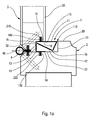
- the door 3 can conventionally define two end positions, a closed position shown in Figure 1a and an open position represented in FIG. 1c. An intermediate position of cracking is represented in FIG. 1b.
- the panel 30 of the door 3 defines with the frame 20 of the amount 2 an angular surface.
- this angular surface defines an angle approximately 90 °.
- the seal 1 according to the invention does not project out of this angular surface and thus remains confined in a dwelling. More generally, the seal does not protrude into space articulation or displacement of the door 3 relative to the amount articulation 2.
- the seal 1 in the closed position, the seal 1 has a folded configuration or curled up so as to advantageously be housed in the localized housing between the door 3 and the amount 2. It is then almost invincible and does not present not the unsightly appearance of the joints of the prior art. As visible on 1a to 1c, the seal 1 covers the hinge 4 in all positions of the door, and thus prevents any risk of introduction of the fingers there. A second seal 40 can be provided on the other side of the hinge 4, if necessary.
- the seal 1 is fixed between the door 3 and the amount
- This attachment provides for the cooperation of the end sections 10, 14 with the respective attachment zones 31, 22 and more particularly the cooperation of the fixing members 100, 150 with the respective recesses 310, 220.
- This attachment can be made by simply fitting, gluing or any other appropriate means.
- the attachment zones 31, 22 may be vis-à-vis one another relative to the closed position of the door.
- Section 11 as shown in Figure 1a can be realized significantly more flexible than the other sections so that a point of inflection 110 is created, especially in the closed position. This point of inflection is then vis-à-vis the inner edge 21 and preferably substantially up to 20.
- the part of the angular surface formed between the amount articulation 2 and section 11 of the joint can then define a surface advantageously regular substantially flat and continuous.
- This features in particular to avoid the presence of a space between said amount 2 and said section 11 so as to avoid the introduction of fingers between the amount 2 and the 3. In any case, even if the user had the possibility to introduce a finger in this space, the pinch would be avoided thanks to the deformability of the section11.
- this section 11 is not necessarily more flexible or more deformable than other sections. Indeed, if section 11 is replaced by two rigid sections articulated around a point of articulation the result would be the same.
- section 13 may be located in the extension of the end section 14 bears against the zone stop 32 so as to facilitate the folding of said seal at the points of inflection or points of articulation 16 and to obtain a folded configuration more stable of said seal 1.
- the seal 1 can be held in the closed position in the housing defined by the attachment zone 31, the inner edge 21, the attachment zone 22, and the stop zone 32.
- This housing can have the shape of a parallelepiped and in this case substantially that of a rectangle in section transverse horizontal.
- the seal completely masks said housing in a closed position so as to avoid any possibility of introduction of fingers.
- the seal is fully unfolded and stretched to its maximum.
- the sections 11, 12, 13 of the joint 1 may have the shape of a curve substantially smooth and steady.
- the seal 1 thus makes it possible to avoid any possibility of pinching fingers between the door 3 and the hinge amount 2, and in all positions, in especially when the door is opened and closed.
- Figures 2a, 2b and 2c show a preferred embodiment of the invention, which differs from the first embodiment above in that the door elements are in this case two leaves 6, 7 of the same door. These leaves 6, 7 are rotatably mounted around a hinge 8 and may have a configuration and a substantially identical dimension or different.
- Such a door with two leaves is for example described in the patent FR 2 447 445, which can be consulted for the structure and operation of a such door.
- These leaves can be framed by a frame and thus mounted on a hinge amount, the formed assembly is then called door block.
- the leaves 6 and 7 each have a face 60, 70, a zone fastening 61, 71 and a flange 62, 72.
- the faces 60 and 70 may be substantially flat or may present some irregularities such as moldings.
- the attachment zones 61, 71 are advantageously located perpendicular to the respective faces 60, 70. These attachment zones each advantageously comprise a respective recess 610, 710 intended for serve as a mounting location.
- the flanges 62, 72 may extend as to them perpendicular to the attachment zones 61, 71 and therefore be substantially parallel to the faces 60, 70.
- the seal 5 comprises example five sections 50, 51, 52, 53, 54 advantageously linear and rectilinear articulated around four points of articulation 55.
- the five sections are divide in this case into two end sections 50, 54 provided each of a respective fastener 500, 540 and in three central sections 51, 52, 53.
- Sections 51 and 53 are located on either side of section 52.
- the sections 51 and 53 are deformable in nature so as to can be folded around a respective inflection point 510, 530, while the section 52 advantageously has a rigid nature so as not to bend easily.
- these sections 51 and 53 could very well each consist of two sections substantially rigid articulated around a point of articulation.
- the leaves 6, 7 are mounted mobile in rotation around a articulation 8 thus making it possible to define a closed position illustrated in FIG. 2a, a half-open position illustrated in FIG. 2b and an open position illustrated in Figure 2c.
- This fixation advantageously implements the cooperation of the fastening 500, 540 end sections 50, 54 with the respective recesses 610, 710, gripping zones 61, 71 in the same manner as in the first embodiment. In the same way, it is possible to ensure that recesses 610, 710 are in the closed position facing each other relative to the other in order to obtain a perfectly symmetrical structure. This fixation can also be done by simple fitting, gluing or any other means appropriate.
- the faces 60 and 70 together define a surface angular with an angle of approximately 180 °.
- the seal adopts a folded or curled configuration so as to be completely confined or retracted in a dwelling located between the two 6, 7.
- the seal 5 completely hides said housing in closed position so as to prohibit access to said housing.
- This accommodation can be a cylinder and particularly can form as shown on the Figure 2a, a parallelepiped and more precisely a rectangular parallelepiped.
- the around this housing then comprises the attachment zone 61, the flanges 62, 72, and the attachment zone 71.
- the seal according to the invention does not project out of the angular surface 60, 70 of the leaves 6, 7 and preferably comes up to the faces 60, 70, that is to say at the height of the 180 ° angular surface.
- inflection points 510, 530 of respective sections 51, 53 are placed substantially in facing relation and may even come in contact.
- the deformability of the sections 51, 53 then makes it possible to avoid any finger pinch between two points of inflection 510, 530 when the door is brought back to the closed position.
- Section 52 can come under sections 51, 53 and even come to press against the flanges 62, 72 to avoid any possibility of insertion of finger (s) at the joint 8 between the two leaves and particularly at the spacing between the two flanges 62, 72.
- Section 51, 53 are then advantageously completely unfolded and can bear against the end of the flanges 62, 72.
- Section 52 positions itself with regard to articulation 8.
- the seal thus covers the hinge 8 in all positions of the door and thus prevents any risk of jamming of fingers while being retracted in the closed position, to improve the aesthetic aspect of the whole.
- the seal of the invention with several articulated and / or deformable sections also improves the functionality of the joint, its effectiveness and compactness and little cumbersome.
Applications Claiming Priority (2)
| Application Number | Priority Date | Filing Date | Title |
|---|---|---|---|
| FR0406318A FR2871507B1 (fr) | 2004-06-11 | 2004-06-11 | Joint de porte anti-pince doigts |
| FR0406318 | 2004-06-11 |
Publications (1)
| Publication Number | Publication Date |
|---|---|
| EP1605130A1 true EP1605130A1 (de) | 2005-12-14 |
Family
ID=34942647
Family Applications (1)
| Application Number | Title | Priority Date | Filing Date |
|---|---|---|---|
| EP05300468A Withdrawn EP1605130A1 (de) | 2004-06-11 | 2005-06-08 | Fingerschutz |
Country Status (2)
| Country | Link |
|---|---|
| EP (1) | EP1605130A1 (de) |
| FR (1) | FR2871507B1 (de) |
Cited By (1)
| Publication number | Priority date | Publication date | Assignee | Title |
|---|---|---|---|---|
| US11286713B2 (en) * | 2020-03-09 | 2022-03-29 | Woods Air Co., Ltd. | Door with finger pinch prevention function |
Citations (3)
| Publication number | Priority date | Publication date | Assignee | Title |
|---|---|---|---|---|
| FR925393A (fr) * | 1946-03-26 | 1947-09-02 | Couvre-joint de sécurité pour portes, fenêtres et similaires | |
| DE9308440U1 (de) * | 1993-06-05 | 1993-08-12 | Hild Tortechnik Gmbh, 35745 Herborn, De | |
| US6643980B1 (en) * | 2002-02-15 | 2003-11-11 | Alvin O. Dorder | Door jamb safety device |
Family Cites Families (1)
| Publication number | Priority date | Publication date | Assignee | Title |
|---|---|---|---|---|
| FR2664936A1 (fr) * | 1990-07-17 | 1992-01-24 | Remia Leon | Piece de menuiserie avec element de securite, du type porte ou fenetre. |
-
2004
- 2004-06-11 FR FR0406318A patent/FR2871507B1/fr not_active Expired - Fee Related
-
2005
- 2005-06-08 EP EP05300468A patent/EP1605130A1/de not_active Withdrawn
Patent Citations (3)
| Publication number | Priority date | Publication date | Assignee | Title |
|---|---|---|---|---|
| FR925393A (fr) * | 1946-03-26 | 1947-09-02 | Couvre-joint de sécurité pour portes, fenêtres et similaires | |
| DE9308440U1 (de) * | 1993-06-05 | 1993-08-12 | Hild Tortechnik Gmbh, 35745 Herborn, De | |
| US6643980B1 (en) * | 2002-02-15 | 2003-11-11 | Alvin O. Dorder | Door jamb safety device |
Cited By (1)
| Publication number | Priority date | Publication date | Assignee | Title |
|---|---|---|---|---|
| US11286713B2 (en) * | 2020-03-09 | 2022-03-29 | Woods Air Co., Ltd. | Door with finger pinch prevention function |
Also Published As
| Publication number | Publication date |
|---|---|
| FR2871507A1 (fr) | 2005-12-16 |
| FR2871507B1 (fr) | 2010-09-10 |
Similar Documents
| Publication | Publication Date | Title |
|---|---|---|
| WO1998044379A1 (fr) | Charniere extensible extra-plate | |
| EP1518734B1 (de) | Rohrförmge Umfangsdichtung zum Anbringen auf den Rand eines Öffnungsrahmens , insbesondere auf eine Kraftfahrzeugkarosserie | |
| EP2481875B1 (de) | Dichtung für Öffnungsflügel, und mit einer solchen Dichtung ausgestatteter Öffnungsflügel | |
| EP1605130A1 (de) | Fingerschutz | |
| EP2148040A1 (de) | Behangvorrichtung insbesondere für Verdunkelungssystem und/oder Gebäudeverschlusssystem | |
| EP1233141A1 (de) | Sicherheitsvorrichtung gegen das Hochschieben von Rolladenpanzer | |
| FR2765617A1 (fr) | Dispositif d'articulation notamment pour planches et rideau mouvant forme de planches assemblees au moyen de tels dispositifs | |
| EP0669445B1 (de) | Profilstab für einen Vorhang und Möbel mit einem derartigen Vorhang | |
| WO2001051274A2 (fr) | Plieuse notamment pour flan plat | |
| EP0733771B1 (de) | Profilierte Leiste für eine vorhangartige Verschlussvorrichtung, Verschlussvorrichtung mit diesen Leisten und Herstellungsverfahren | |
| EP0845332B1 (de) | Vorrichtung zum Befestigen von Dichtungslippen | |
| WO2020104733A1 (fr) | Profile souple | |
| EP0156736A1 (de) | Profilierter Dichtungsstreifen, insbesondere für Fahrzeugschiebetüren | |
| FR2878888A1 (fr) | Dispositif de maintien d'une lame de tablier de volet roulant a l'interieur d'une coulisse laterale de ce volet | |
| FR2711719A1 (fr) | Perfectionnement aux paumelles d'articulation d'un ouvrant sur un dormant. | |
| CH631392A5 (fr) | Balai d'essuie-glace. | |
| FR2844166A1 (fr) | Dispositif comprenant au moins deux panneaux articules | |
| EP0670408B1 (de) | Deflektor für den unteren Querbalken eines Tür- oder Fensterrahmens oder dergleichen | |
| EP3561575A1 (de) | Scharnier ohne zapfenschraube für brillengestell | |
| FR2818306A1 (fr) | Charniere pour element de survitrage et moulure associee | |
| FR2717217A1 (fr) | Dispositif de fixation d'un châssis de survitrage sur le cadre existant d'une fenêtre. | |
| EP2845983B1 (de) | Rollladenpanzer mit einer Verbindungsvorrichtung von zwei Lamellen | |
| FR2712656A1 (fr) | Dispositif de profilé d'étanchéité. | |
| FR2843994A1 (fr) | Vantail pour porte sectionnelle et porte comprenant un tel vantail | |
| FR2831073A1 (fr) | Construction du genre maquette de batiment et la piece d'assemblage de parois pour la realisation de cette construction |
Legal Events
| Date | Code | Title | Description |
|---|---|---|---|
| PUAI | Public reference made under article 153(3) epc to a published international application that has entered the european phase |
Free format text: ORIGINAL CODE: 0009012 |
|
| AK | Designated contracting states |
Kind code of ref document: A1 Designated state(s): AT BE BG CH CY CZ DE DK EE ES FI FR GB GR HU IE IS IT LI LT LU MC NL PL PT RO SE SI SK TR |
|
| AX | Request for extension of the european patent |
Extension state: AL BA HR LV MK YU |
|
| 17P | Request for examination filed |
Effective date: 20060609 |
|
| AKX | Designation fees paid |
Designated state(s): BE GB LU |
|
| REG | Reference to a national code |
Ref country code: DE Ref legal event code: 8566 |
|
| 17Q | First examination report despatched |
Effective date: 20120831 |
|
| STAA | Information on the status of an ep patent application or granted ep patent |
Free format text: STATUS: THE APPLICATION IS DEEMED TO BE WITHDRAWN |
|
| 18D | Application deemed to be withdrawn |
Effective date: 20130111 |