EP1605130A1 - Finger guard - Google Patents
Finger guard Download PDFInfo
- Publication number
- EP1605130A1 EP1605130A1 EP05300468A EP05300468A EP1605130A1 EP 1605130 A1 EP1605130 A1 EP 1605130A1 EP 05300468 A EP05300468 A EP 05300468A EP 05300468 A EP05300468 A EP 05300468A EP 1605130 A1 EP1605130 A1 EP 1605130A1
- Authority
- EP
- European Patent Office
- Prior art keywords
- door
- seal
- closed position
- deformable
- section
- Prior art date
- Legal status (The legal status is an assumption and is not a legal conclusion. Google has not performed a legal analysis and makes no representation as to the accuracy of the status listed.)
- Withdrawn
Links
Images


Classifications
-
- E—FIXED CONSTRUCTIONS
- E06—DOORS, WINDOWS, SHUTTERS, OR ROLLER BLINDS IN GENERAL; LADDERS
- E06B—FIXED OR MOVABLE CLOSURES FOR OPENINGS IN BUILDINGS, VEHICLES, FENCES OR LIKE ENCLOSURES IN GENERAL, e.g. DOORS, WINDOWS, BLINDS, GATES
- E06B7/00—Special arrangements or measures in connection with doors or windows
- E06B7/28—Other arrangements on doors or windows, e.g. door-plates, windows adapted to carry plants, hooks for window cleaners
- E06B7/36—Finger guards or other measures preventing harmful access between the door and the door frame
- E06B7/367—Finger guards or other measures preventing harmful access between the door and the door frame by covering the gap between the door and the door frame at the hinge side
Definitions
- the present invention relates to a door seal and particularly to a anti-finger clamp seal to be interposed between door members.
- the present invention also relates to a door comprising such a joint and a door block comprising such a door.
- a disadvantage related to the seal disclosed in DE 93 08 440 is that this joint occupies a very important place in the articulation space and is thus widely visible to a user which confers a particular effect unsightly.
- the document FR 2 664 936 discloses a flexible blade mounted in the articulation space of the door elements having a free end slidable in a recess in one of said door members so as to prohibit access to the articulation space.
- Such a mode of realization therefore requires specific, tedious and expensive door elements.
- excessive friction of the blade against walls of the recess may cause difficulties in relative movement of two door elements, in particular when moving the door of a door open position to a closed position.
- document FR 925 393 discloses an accordion seal positioned between two door elements. As seen in Figure 3 of this document such a seal is inefficient and in no way annihilates the possibility of get your fingers caught between the two door elements.
- the present invention aims to overcome these disadvantages of the art previous by improving the existing joints.
- the present invention also aims to interpose a seal between door elements so as to obtain a more harmonious and better finished ensemble.
- the present invention also aims to develop a seal easy to manufacture, to ask and low cost.
- Another object of the present invention is to provide an alternative form of joints with respect to the joints disclosed in the prior art, this form alternative being safer, easier to assemble and more aesthetic.
- the present invention provides a door seal anti-finger clamp intended to be interposed between door elements, at least one of said door elements being rotatable relative to the other around of a hinge, said door elements moving angularly between a closed position and an open position, said door seal covering said articulation in all positions of said door elements, and in the closed position, said door elements together defining an angular surface, said gasket not protruding out of said angular surface in this closed position, said seal having at least two sections of deformable nature, each section of deformable nature having a point of inflection, said point of inflection of a section of deformable nature lying opposite said point inflection of the other section of deformable nature in the closed position.
- said elements of door are at least two leaves of the same door, said angular surface forming an angle of approximately 180 ° in the closed position.
- said angular surface defined by said elements of door form with said seal a substantially flat and continuous surface.
- said seal is entirely confined in closed position in a dwelling.
- said housing has a configuration cuboid.
- said seal masks said housing in the closed position.
- said housing comprises at least one zone hooking for maintaining said seal between said door members.
- said housing comprises two attachment zones, said attachment zones being located on each door element substantially vis-à-vis one relative to the other in the closed position.
- said seal adopts a folded configuration in position closed and unfolded configuration in open position.
- said seal comprises several sections articulating the to each other at the points of articulation.
- said sections comprise at least one section of rigid nature.
- said section of rigid nature is flanked by two deformable sections.
- said two deformable sections form together a regular, substantially flat and continuous surface at which said point of inflection of a deformable section comes into contact with said point of inflection of the other deformable section so as to avoid any space between said inflection points.
- the present invention also provides a door having a seal of door.
- the present invention further relates to a door block comprising a door.
- the present invention comprises elements of door and an anti-finger clamp seal interposed between said door members.
- the door elements are a door 3 and a hinge amount 2 of a frame framing said door.
- the assembly forms a door block.
- the door 3 is made of wood or metal. It has a sign 30 advantageously provided with an attachment zone 31 and an abutment zone 32.
- the panel 30 may define a substantially planar surface or a surface irregular provided with moldings.
- the attachment zone 31 is advantageously perpendicular to the panel 30.
- This attachment zone 31 has a recess 310 advantageously comprising two side walls vis-à-vis connected to a soul background to define a mounting location.
- the abutment zone 32 is itself adjacent and may be perpendicular at the attachment zone 31.
- the hinge amount 2 is made of wood or metal. It has a frame 20, an inner edge 21 and a hooking zone 22. This amount 2 is intended to be fixed on a frame, wall or masonry.
- the frame 20 defines a substantially flat surface.
- the inner edge 21 as shown in the figures, can extend substantially perpendicular to the frame 20.
- the attachment zone 22 is in turn an extension of the inner edge 21 and can be advantageously substantially perpendicular to this internal edge 21.
- a recess 220 is provided at this zone hooking 22 may have the same configuration as the recess 310 of the attachment zone 31 of the door panel 30.
- the seal 1 comprises advantageously five sections 10, 11, 12, 13, 14, preferably linear and rectilinear, articulated around four points of articulation 15.
- the five sections in this case include two end sections 10, 14 and three sections 11, 12, 13.
- the two end sections 10, 14 may comprise a fixing member 100, 150 being in the form of a projection.
- the sections of the joint may be of a rigid nature or of a nature deformable.
- these sections will be advantageously articulated with respect to each other at points of articulation, comparable to parts of joint of lesser thickness for example.
- section deformable nature the flexible nature of the sections could suffice to articulate sections relative to each other. In both cases, the goal is to have a seal able to bend and unfold, for example such an accordion.
- the door 3 is mounted mobile in rotation on the amount 2 around a joint 4.
- This articulation 4 may for example be constituted of hinges.
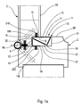
- the door 3 can conventionally define two end positions, a closed position shown in Figure 1a and an open position represented in FIG. 1c. An intermediate position of cracking is represented in FIG. 1b.
- the panel 30 of the door 3 defines with the frame 20 of the amount 2 an angular surface.
- this angular surface defines an angle approximately 90 °.
- the seal 1 according to the invention does not project out of this angular surface and thus remains confined in a dwelling. More generally, the seal does not protrude into space articulation or displacement of the door 3 relative to the amount articulation 2.
- the seal 1 in the closed position, the seal 1 has a folded configuration or curled up so as to advantageously be housed in the localized housing between the door 3 and the amount 2. It is then almost invincible and does not present not the unsightly appearance of the joints of the prior art. As visible on 1a to 1c, the seal 1 covers the hinge 4 in all positions of the door, and thus prevents any risk of introduction of the fingers there. A second seal 40 can be provided on the other side of the hinge 4, if necessary.
- the seal 1 is fixed between the door 3 and the amount
- This attachment provides for the cooperation of the end sections 10, 14 with the respective attachment zones 31, 22 and more particularly the cooperation of the fixing members 100, 150 with the respective recesses 310, 220.
- This attachment can be made by simply fitting, gluing or any other appropriate means.
- the attachment zones 31, 22 may be vis-à-vis one another relative to the closed position of the door.
- Section 11 as shown in Figure 1a can be realized significantly more flexible than the other sections so that a point of inflection 110 is created, especially in the closed position. This point of inflection is then vis-à-vis the inner edge 21 and preferably substantially up to 20.
- the part of the angular surface formed between the amount articulation 2 and section 11 of the joint can then define a surface advantageously regular substantially flat and continuous.
- This features in particular to avoid the presence of a space between said amount 2 and said section 11 so as to avoid the introduction of fingers between the amount 2 and the 3. In any case, even if the user had the possibility to introduce a finger in this space, the pinch would be avoided thanks to the deformability of the section11.
- this section 11 is not necessarily more flexible or more deformable than other sections. Indeed, if section 11 is replaced by two rigid sections articulated around a point of articulation the result would be the same.
- section 13 may be located in the extension of the end section 14 bears against the zone stop 32 so as to facilitate the folding of said seal at the points of inflection or points of articulation 16 and to obtain a folded configuration more stable of said seal 1.
- the seal 1 can be held in the closed position in the housing defined by the attachment zone 31, the inner edge 21, the attachment zone 22, and the stop zone 32.
- This housing can have the shape of a parallelepiped and in this case substantially that of a rectangle in section transverse horizontal.
- the seal completely masks said housing in a closed position so as to avoid any possibility of introduction of fingers.
- the seal is fully unfolded and stretched to its maximum.
- the sections 11, 12, 13 of the joint 1 may have the shape of a curve substantially smooth and steady.
- the seal 1 thus makes it possible to avoid any possibility of pinching fingers between the door 3 and the hinge amount 2, and in all positions, in especially when the door is opened and closed.
- Figures 2a, 2b and 2c show a preferred embodiment of the invention, which differs from the first embodiment above in that the door elements are in this case two leaves 6, 7 of the same door. These leaves 6, 7 are rotatably mounted around a hinge 8 and may have a configuration and a substantially identical dimension or different.
- Such a door with two leaves is for example described in the patent FR 2 447 445, which can be consulted for the structure and operation of a such door.
- These leaves can be framed by a frame and thus mounted on a hinge amount, the formed assembly is then called door block.
- the leaves 6 and 7 each have a face 60, 70, a zone fastening 61, 71 and a flange 62, 72.
- the faces 60 and 70 may be substantially flat or may present some irregularities such as moldings.
- the attachment zones 61, 71 are advantageously located perpendicular to the respective faces 60, 70. These attachment zones each advantageously comprise a respective recess 610, 710 intended for serve as a mounting location.
- the flanges 62, 72 may extend as to them perpendicular to the attachment zones 61, 71 and therefore be substantially parallel to the faces 60, 70.
- the seal 5 comprises example five sections 50, 51, 52, 53, 54 advantageously linear and rectilinear articulated around four points of articulation 55.
- the five sections are divide in this case into two end sections 50, 54 provided each of a respective fastener 500, 540 and in three central sections 51, 52, 53.
- Sections 51 and 53 are located on either side of section 52.
- the sections 51 and 53 are deformable in nature so as to can be folded around a respective inflection point 510, 530, while the section 52 advantageously has a rigid nature so as not to bend easily.
- these sections 51 and 53 could very well each consist of two sections substantially rigid articulated around a point of articulation.
- the leaves 6, 7 are mounted mobile in rotation around a articulation 8 thus making it possible to define a closed position illustrated in FIG. 2a, a half-open position illustrated in FIG. 2b and an open position illustrated in Figure 2c.
- This fixation advantageously implements the cooperation of the fastening 500, 540 end sections 50, 54 with the respective recesses 610, 710, gripping zones 61, 71 in the same manner as in the first embodiment. In the same way, it is possible to ensure that recesses 610, 710 are in the closed position facing each other relative to the other in order to obtain a perfectly symmetrical structure. This fixation can also be done by simple fitting, gluing or any other means appropriate.
- the faces 60 and 70 together define a surface angular with an angle of approximately 180 °.
- the seal adopts a folded or curled configuration so as to be completely confined or retracted in a dwelling located between the two 6, 7.
- the seal 5 completely hides said housing in closed position so as to prohibit access to said housing.
- This accommodation can be a cylinder and particularly can form as shown on the Figure 2a, a parallelepiped and more precisely a rectangular parallelepiped.
- the around this housing then comprises the attachment zone 61, the flanges 62, 72, and the attachment zone 71.
- the seal according to the invention does not project out of the angular surface 60, 70 of the leaves 6, 7 and preferably comes up to the faces 60, 70, that is to say at the height of the 180 ° angular surface.
- inflection points 510, 530 of respective sections 51, 53 are placed substantially in facing relation and may even come in contact.
- the deformability of the sections 51, 53 then makes it possible to avoid any finger pinch between two points of inflection 510, 530 when the door is brought back to the closed position.
- Section 52 can come under sections 51, 53 and even come to press against the flanges 62, 72 to avoid any possibility of insertion of finger (s) at the joint 8 between the two leaves and particularly at the spacing between the two flanges 62, 72.
- Section 51, 53 are then advantageously completely unfolded and can bear against the end of the flanges 62, 72.
- Section 52 positions itself with regard to articulation 8.
- the seal thus covers the hinge 8 in all positions of the door and thus prevents any risk of jamming of fingers while being retracted in the closed position, to improve the aesthetic aspect of the whole.
- the seal of the invention with several articulated and / or deformable sections also improves the functionality of the joint, its effectiveness and compactness and little cumbersome.
Abstract
Description
La présente invention concerne un joint de porte et particulièrement un joint anti-pince doigts destiné à être interposé entre des éléments de porte. La présente invention concerne également une porte comportant un tel joint ainsi qu'un bloc porte comportant une telle porte.The present invention relates to a door seal and particularly to a anti-finger clamp seal to be interposed between door members. The The present invention also relates to a door comprising such a joint and a door block comprising such a door.
Dans l'état de la technique, il est connu de placer un joint anti-pince doigt entre deux éléments de porte lorsqu'au moins un élément est mobile en rotation par rapport à l'autre. Ce joint fait ainsi obstacle à l'introduction de doigt(s) dans l'espace autour duquel s'articulent les éléments. Généralement, le joint est ancré sur des supports de fixation situés sur chaque élément de porte de part et d'autre de l'espace d'articulation de façon à constituer un pont reliant lesdits éléments. Ce pont recouvre ainsi l'espace d'articulation et interdit donc l'accès à cet espace. Un tel joint est généralement réalisé en matériau souple déformable de façon à pouvoir adopter une configuration allongée lorsqu'un élément pivote en éloignement de l'autre et une configuration ployée en boucle saillante lorsqu'un élément pivote en rapprochement de l'autre. Cette boucle saillante atteint généralement sa dimension maximale en position de rapprochement maximal des éléments de porte c'est-à-dire en position fermée.In the state of the art, it is known to place an anti-finger clamp seal between two door members when at least one member is rotatable compared to each other. This seal thus prevents the introduction of finger (s) into the space around which the elements are articulated. Generally, the seal is anchored on mounting brackets located on each door element on either side of the articulation space so as to constitute a bridge connecting said elements. This bridge thus covers the articulation space and therefore prohibits access to this space. Such a seal is generally made of flexible deformable material of to be able to adopt an elongated configuration when an element pivots in away from the other and a bent configuration protruding when a element pivots closer to each other. This striking loop reaches generally its maximum dimension in maximum approach position door elements that is to say in closed position.
Toutefois, cette caractéristique selon laquelle le joint ploie et forme une boucle faisant saillie dans l'espace d'articulation lorsque les éléments de porte se rapprochent l'un vers l'autre constitue un inconvénient majeur. En effet, cette boucle présente un aspect inesthétique non négligeable auquel il convient de remédier.However, this characteristic that the joint bends and forms a loop protruding into the hinge space when the door elements are move toward each other is a major disadvantage. Indeed, this loop has an unsightly appearance that is not negligible remedy.
Les documents DE 93 08 440, FR 2 664 936 et FR 925 393 divulguent des
exemples de réalisation de joints dans lesquels les joints ne font pas saillie par
rapport aux éléments de porte lorsque ces éléments de porte sont en position
fermée. Toutefois ces joints de l'art antérieur présente tous des inconvénients
non négligeables.Documents DE 93 08 440,
Un inconvénient lié au joint divulgué dans le document DE 93 08 440 est que ce joint occupe une place très importante dans l'espace d'articulation et est ainsi largement visible pour un utilisateur ce qui confère un effet particulièrement inesthétique.A disadvantage related to the seal disclosed in DE 93 08 440 is that this joint occupies a very important place in the articulation space and is thus widely visible to a user which confers a particular effect unsightly.
Le document FR 2 664 936 divulgue quant à lui une lame souple montée
dans l'espace d'articulation des éléments de porte présentant une extrémité libre
apte à coulisser dans un évidement ménagé dans l'un desdits éléments de porte
de manière à interdire l'accès à l'espace d'articulation. Un tel mode de
réalisation nécessite donc des aménagements spécifiques, fastidieux et coûteux
des éléments de porte. De plus, un frottement excessif de la lame contre les
parois de l'évidement peut occasionner des difficultés de déplacement relatif des
deux éléments de porte, notamment lors du déplacement de la porte d'une
position ouverte vers une position fermée.The
Enfin, le document FR 925 393 divulgue un joint en accordéon positionné entre deux éléments de porte. Tel que visible sur la figure 3 de ce document un tel joint est peu efficace et n'annihile en aucun cas la possibilité de se coincer les doigts entre les deux éléments de porte.Finally, document FR 925 393 discloses an accordion seal positioned between two door elements. As seen in Figure 3 of this document such a seal is inefficient and in no way annihilates the possibility of get your fingers caught between the two door elements.
La présente invention a pour but de palier ces inconvénients de l'art antérieur en améliorant les joints existants.The present invention aims to overcome these disadvantages of the art previous by improving the existing joints.
La présente invention a encore pour but d'interposer un joint entre des éléments de porte de sorte à obtenir un ensemble plus harmonieux et mieux fini.The present invention also aims to interpose a seal between door elements so as to obtain a more harmonious and better finished ensemble.
La présente invention a également pour but de mettre au point un joint facile à fabriquer, à poser et de faible coût de revient.The present invention also aims to develop a seal easy to manufacture, to ask and low cost.
La présente invention a encore pour but de fournir une forme alternative de joints par rapport aux joints divulgués dans l'art antérieur, cette forme alternative étant plus sûr, plus facile à monter et plus esthétique.Another object of the present invention is to provide an alternative form of joints with respect to the joints disclosed in the prior art, this form alternative being safer, easier to assemble and more aesthetic.
Pour atteindre ces buts, la présente invention propose un joint de porte anti-pince doigts destiné à être interposé entre des éléments de porte, au moins un desdits éléments de porte étant mobile en rotation par rapport à l'autre autour d'une articulation, lesdits éléments de porte se déplaçant angulairement entre une position fermée et une position ouverte, ledit joint de porte recouvrant ladite articulation en toutes positions desdits éléments de porte, et en position fermée, lesdits éléments de porte définissant ensemble une surface angulaire, ledit joint ne faisant pas saillie hors de ladite surface angulaire dans cette position fermée, ledit joint comportant au moins deux sections de nature déformable, chaque section de nature déformable comportant un point d'inflexion, ledit point d'inflexion d'une section de nature déformable se situant en vis-à-vis dudit point d'inflexion de l'autre section de nature déformable en position fermée.To achieve these goals, the present invention provides a door seal anti-finger clamp intended to be interposed between door elements, at least one of said door elements being rotatable relative to the other around of a hinge, said door elements moving angularly between a closed position and an open position, said door seal covering said articulation in all positions of said door elements, and in the closed position, said door elements together defining an angular surface, said gasket not protruding out of said angular surface in this closed position, said seal having at least two sections of deformable nature, each section of deformable nature having a point of inflection, said point of inflection of a section of deformable nature lying opposite said point inflection of the other section of deformable nature in the closed position.
Selon un premier mode de réalisation avantageux, lesdits éléments de porte sont au moins deux vantaux d'une même porte, ladite surface angulaire formant un angle d'approximativement 180° en position fermée.According to a first advantageous embodiment, said elements of door are at least two leaves of the same door, said angular surface forming an angle of approximately 180 ° in the closed position.
Avantageusement, ladite surface angulaire définie par lesdits éléments de porte forme avec ledit joint une surface sensiblement plane et continue.Advantageously, said angular surface defined by said elements of door form with said seal a substantially flat and continuous surface.
Avantageusement, ledit joint est entièrement confiné en position fermée dans un logement.Advantageously, said seal is entirely confined in closed position in a dwelling.
Avantageusement, ledit logement présente une configuration parallélépipédique.Advantageously, said housing has a configuration cuboid.
Avantageusement, ledit joint masque ledit logement en position fermée.Advantageously, said seal masks said housing in the closed position.
Avantageusement, ledit logement comprend au moins une zone d'accrochage pour le maintien dudit joint entre lesdits éléments de porte.Advantageously, said housing comprises at least one zone hooking for maintaining said seal between said door members.
Avantageusement, ledit logement comporte deux zones d'accrochage, lesdites zones d'accrochage étant situées sur chaque élément de porte sensiblement en vis-à-vis l'une par rapport à l'autre en position fermée.Advantageously, said housing comprises two attachment zones, said attachment zones being located on each door element substantially vis-à-vis one relative to the other in the closed position.
Avantageusement, ledit joint adopte une configuration pliée en position fermée et une configuration dépliée en position ouverte.Advantageously, said seal adopts a folded configuration in position closed and unfolded configuration in open position.
Avantageusement, ledit joint comprend plusieurs sections s'articulant les unes par rapport aux autres au niveau de points d'articulation.Advantageously, said seal comprises several sections articulating the to each other at the points of articulation.
Avantageusement, lesdites sections comprennent au moins une section de nature rigide.Advantageously, said sections comprise at least one section of rigid nature.
Avantageusement, ladite section de nature rigide est flanquée par deux sections déformables.Advantageously, said section of rigid nature is flanked by two deformable sections.
Avantageusement, lesdites deux sections déformables forment ensemble une surface régulière, sensiblement plane et continue au niveau de laquelle ledit point d'inflexion d'une section déformable vient au contact dudit point d'inflexion de l'autre section déformable de sorte à éviter tout espace entre lesdits points d'inflexion.Advantageously, said two deformable sections form together a regular, substantially flat and continuous surface at which said point of inflection of a deformable section comes into contact with said point of inflection of the other deformable section so as to avoid any space between said inflection points.
La présente invention propose également, une porte comportant un joint de porte.The present invention also provides a door having a seal of door.
La présente invention concerne encore un bloc porte comportant une porte.The present invention further relates to a door block comprising a door.
L'invention sera maintenant plus amplement décrite en référence aux dessins joints donnant à titre d'exemples non limitatifs deux modes de réalisation de l'invention.The invention will now be further described with reference to attached drawings giving as non-limiting examples two embodiments of the invention.
Sur les figures :
- la figure 1a est une vue en section transversale horizontale d'un joint interposé entre des éléments de porte en position fermée,
- la figure 1b est une vue similaire à la figure 1a représentant le joint interposé entre des éléments de porte en position d'entrebâillement,
- la figure 1c est une vue également similaire à la figure 1a représentant le joint interposé entre des éléments de porte en position ouverte,
- la figure 2a est une vue en section transversale horizontale d'un joint selon un mode de réalisation de l'invention interposé entre des éléments de porte en position fermée,
- la figure 2b est une vue similaire à la figure 2a représentant le joint interposé entre des éléments de porte en position d'entrebâillement,
- la figure 2c est également une vue similaire à la figure 2a représentant le joint interposé entre des éléments de porte en position ouverte.
- FIG. 1a is a horizontal cross-sectional view of a seal interposed between door elements in the closed position,
- FIG. 1b is a view similar to FIG. 1a showing the seal interposed between door elements in half-open position,
- FIG. 1c is a view also similar to FIG. 1a showing the seal interposed between door elements in the open position,
- FIG. 2a is a horizontal cross-sectional view of a seal according to one embodiment of the invention interposed between door elements in the closed position,
- FIG. 2b is a view similar to FIG. 2a showing the seal interposed between door elements in half-open position,
- Figure 2c is also a view similar to Figure 2a showing the seal interposed between door members in the open position.
En référence aux figures, la présente invention comporte des éléments de porte et un joint anti-pince doigt intercalé entre lesdits éléments de porte.With reference to the figures, the present invention comprises elements of door and an anti-finger clamp seal interposed between said door members.
Deux modes de réalisation vont maintenant être décrits. Two embodiments will now be described.
Dans le premier mode de réalisation représenté en figure 1a, 1b et 1c, les
éléments de porte sont une porte 3 et un montant d'articulation 2 d'une huisserie
encadrant ladite porte. Ainsi, l'ensemble forme un bloc-porte.In the first embodiment represented in FIGS. 1a, 1b and 1c, the
door elements are a
La porte 3 est réalisée en bois ou en métal. Elle comporte un panneau 30
avantageusement pourvu d'une zone d'accrochage 31 et d'une zone de butée 32.The
Le panneau 30 peut définir une surface sensiblement plane ou une surface
irrégulière prévue avec des moulures.The
La zone d'accrochage 31 est avantageusement perpendiculaire au
panneau 30. Cette zone d'accrochage 31 comporte un évidement 310
comprenant avantageusement deux parois latérales en vis-à-vis reliées à une âme
de fond afin de définir un emplacement de fixation.The
La zone de butée 32 est quant à elle adjacente et peut être perpendiculaire
à la zone d'accrochage 31.The
Le montant d'articulation 2 est réalisé en bois ou en métal. Il comporte un
encadrement 20, un bord interne 21 et une zone d'accrochage 22. Ce montant 2
est destiné à être disposé fixement sur un bâti, un mur ou une maçonnerie.The
L'encadrement 20 définit une surface sensiblement plane.The
Le bord interne 21 tel que représenté sur les figures, peut s'étendre
sensiblement perpendiculairement à l'encadrement 20.The
La zone d'accrochage 22 se situe quant à elle dans le prolongement du
bord interne 21 et peut être avantageusement sensiblement perpendiculaire à ce
bord interne 21. Un évidement 220 est ménagé au niveau de cette zone
d'accrochage 22 pouvant présenter la même configuration que l'évidement 310
de la zone d'accrochage 31 du panneau de porte 30.The
Dans ce premier mode de réalisation, le joint 1 comporte
avantageusement cinq sections 10, 11, 12, 13, 14, de préférence linéaires et
rectilignes, articulées autour de quatre points d'articulation 15. Les cinq sections
comprennent dans ce cas deux sections d'extrémité 10, 14 et trois sections
centrales 11, 12, 13. Les deux sections d'extrémité 10, 14 peuvent comporter un
organe de fixation 100, 150 se présentant sous la forme d'une projection. In this first embodiment, the
Les sections du joint peuvent être de nature rigide ou de nature déformable. Dans le cas de sections rigides, ces sections seront avantageusement articulées les unes par rapport aux autres au niveau de points d'articulation, assimilables à des parties de joint de moindre épaisseur par exemple. Dans le cas de section de nature déformable, le caractère souple des sections pourrait suffire à articuler les sections les unes par rapport aux autres. Dans les deux cas, le but est d'avoir un joint apte à se plier et se déplier, par exemple tel un accordéon.The sections of the joint may be of a rigid nature or of a nature deformable. In the case of rigid sections, these sections will be advantageously articulated with respect to each other at points of articulation, comparable to parts of joint of lesser thickness for example. In the case of section deformable nature, the flexible nature of the sections could suffice to articulate sections relative to each other. In both cases, the goal is to have a seal able to bend and unfold, for example such an accordion.
Assemblée, la porte 3 est montée mobile en rotation sur le montant 2
autours d'une articulation 4. Cette articulation 4 peut par exemple être constituée
de paumelles.Assembly, the
La porte 3 peut de manière classique définir deux positions d'extrémité,
une position fermée représentée sur la figure 1a et une position ouverte
représentée sur la figure 1c. Une position intermédiaire d'entrebâillement est
représentée sur la figure 1b.The
Dans ces différentes positions, le panneau 30 de la porte 3 définit avec
l'encadrement 20 du montant 2 une surface angulaire.In these different positions, the
En position fermée, cette surface angulaire définit un angle
d'approximativement 90°. Tel que visible sur la figure 1a, le joint 1 selon
l'invention ne fait pas saillie hors de cette surface angulaire et reste ainsi confinée
dans un logement. Plus généralement, le joint ne fait pas saillie dans l'espace
d'articulation ou de débattement de la porte 3 par rapport au montant
d'articulation 2.In the closed position, this angular surface defines an angle
approximately 90 °. As can be seen in FIG. 1a, the
En effet, en position fermée, le joint 1 présente une configuration pliée ou
recroquevillée de sorte à avantageusement être hébergé dans le logement localisé
entre la porte 3 et le montant 2. Il est alors quasiment invincible et ne présente
pas l'aspect inesthétique des joints de l'art antérieur. Comme visible sur les
figures 1a à 1c, le joint 1 recouvre l'articulation 4 en toutes positions de la porte,
et empêche donc tout risque d'introduction des doigts à cet endroit. Un second
joint 40 peut être prévu de l'autre côté de l'articulation 4, si nécessaire.Indeed, in the closed position, the
Avantageusement, le joint 1 est fixé entre la porte 3 et le montant
d'articulation 2. Cette fixation prévoit la coopération des sections d'extrémité 10,
14 avec les zones d'accrochage respectives 31, 22 et plus particulièrement la
coopération des organes de fixation 100, 150 avec les évidements respectifs 310,
220. Cette fixation peut être réalisée par simple emmanchement, collage ou tout
autres moyens appropriés. Il est à noter que les zones d'accrochage 31, 22
peuvent être en vis-à-vis l'une par rapport à l'autre dans la position fermée de la
porte. La section 11 telle que représentée sur la figure 1a peut être réalisée
sensiblement plus souple que les autres sections de sorte qu'un point d'inflexion
110 est crée, notamment en position fermée. Ce point d'inflexion se place alors
en vis-à-vis du bord interne 21 et de préférence sensiblement à hauteur de
l'encadrement 20. Ainsi, la partie de la surface angulaire formée entre le montant
d'articulation 2 et la section 11 du joint peut alors définir une surface
avantageusement régulière sensiblement plane et continue. Cette caractéristiques
a notamment pour but d'éviter la présence d'un espace entre ledit montant 2 et
ladite section 11 de façon à éviter l'introduction de doigts entre le montant 2 et la
porte 3. De toute façon, même si l'utilisateur avait la possibilité d'introduire un
doigt dans cet espace, le pincement serait évité grâce à la déformabilité de la
section11. Toutefois, il est à noter que cette section 11 n'est pas obligatoirement
plus souple ou plus déformable que les autres sections. En effet, si la section 11
est remplacée par deux sections rigides articulées autour d'un point d'articulation
le résultat serait le même. D'autre part, il peut être prévu que la section 13 située
dans le prolongement de la section d'extrémité 14 vienne en appui contre la zone
de butée 32 de façon à faciliter le pliage dudit joint au niveau des points
d'inflexion ou des points d'articulations 16 et obtenir une configuration pliée
plus stable dudit joint 1.Advantageously, the
Ainsi, le joint 1 peut être maintenu en position fermée dans le logement
délimité par la zone d'accrochage 31, le bord interne 21, la zone d'accrochage
22, et la zone de butée 32. Ce logement peut présenter la forme d'un
parallélépipède et dans ce cas sensiblement celle d'un rectangle en section
transversale horizontale. Avantageusement, le joint masque complètement ledit
logement en position fermée de sorte à éviter toute possibilité d'introduction de
doigts. Thus, the
Lors de l'ouverture de la porte 3, celle-ci tourne autour de l'articulation 4.
En position d'entrebâillement représentée sur la figure 1b, le joint se déplie
progressivement au niveau du/des point(s) d'inflexion 110 et/ou d'articulation
15.When opening the
Enfin, en position ouverte représentée sur la figure c, le joint est
entièrement déplié et est étiré à son maximum. Dans ce dernier cas, les sections
centrales 11, 12, 13 du joint 1 peuvent avoir la forme d'une courbe sensiblement
lisse et régulière.Finally, in the open position shown in Figure c, the seal is
fully unfolded and stretched to its maximum. In the latter case, the
Le joint 1 permet ainsi d'éviter toute possibilité de pincement de doigts
entre la porte 3 et le montant d'articulation 2, et ce en toutes positions, en
particulier lorsque la porte est ouverte et refermée.The
Les figures 2a, 2b et 2c représentent un mode de réalisation avantageux
de l'invention, qui diffère du premier mode de réalisation ci-dessus en ce que les
éléments de porte sont dans ce cas deux vantaux 6, 7 d'une même porte. Ces
vantaux 6, 7 sont montés mobiles en rotation autour d'une articulation 8 et
peuvent présenter une configuration et une dimension sensiblement identique ou
différente. Une telle porte à deux vantaux est par exemple décrite dans le brevet
FR 2 447 445, qui peut être consulté pour la structure et le fonctionnement d'une
telle porte. Ces vantaux peuvent être encadrés par une huisserie et ainsi montés
sur un montant d'articulation, l'ensemble formé est alors appelé bloc-porte.Figures 2a, 2b and 2c show a preferred embodiment
of the invention, which differs from the first embodiment above in that the
door elements are in this case two
Les vantaux 6 et 7 présentent chacun une face 60, 70, une zone
d'accrochage 61, 71 et un rebord 62, 72.The
Les faces 60 et 70 peuvent être sensiblement planes ou peuvent présenter certaines irrégularités telles que des moulures.The faces 60 and 70 may be substantially flat or may present some irregularities such as moldings.
Les zones d'accrochage 61, 71 se situent avantageusement
perpendiculairement aux faces respectives 60, 70. Ces zones d'accrochage
comportent avantageusement chacune un évidement respectif 610, 710 destiné à
servir d'emplacement de fixation. Les rebords 62, 72 peuvent s'étendre quant à
eux perpendiculairement aux zones d'accrochage 61, 71 et donc être
sensiblement parallèles aux faces 60, 70. The
Le joint 5 selon ce mode de réalisation de l'invention comporte par
exemple cinq sections 50, 51, 52, 53, 54 avantageusement linéaires et rectilignes
articulées autour de quatre points d'articulation 55. Les cinq sections se
répartissent dans le cas présent en deux sections d'extrémité 50, 54 pourvues
chacune d'un organe de fixation respectif 500, 540 et en trois sections centrales
51, 52, 53. Les sections 51 et 53 sont situées de part et d'autre de la section 52.
Avantageusement, les sections 51 et 53 sont de nature déformable de façon à
pouvoir être pliées autour d'un point d'inflexion respectif 510, 530, alors que la
section 52 présente avantageusement une nature rigide de sorte à ne pas ployer
aisément. Toutefois, comme dans le mode de réalisation précédent, ces sections
51 et 53 pourraient très bien chacune être composée de deux sections
sensiblement rigides articulées autour d'un point d'articulation.The
Assemblés, les vantaux 6, 7 sont montés mobiles en rotation autour d'une
articulation 8 permettant ainsi de définir une position fermée illustrée en figure
2a, une position d'entrebâillement illustrée en figure 2b et une position ouverte
illustrée en figure 2c.Assembled, the
Dans toutes ces positions, le joint est intercalé entre les deux vantaux 6, 7.
Cette fixation met avantageusement en oeuvre la coopération des organes de
fixation 500, 540 des sections d'extrémité 50, 54 avec les évidements respectifs
610, 710, des zones d'accrochage 61, 71 de la même manière que dans le premier
mode de réalisation. De la même façon, il est possible de faire en sorte que les
évidements 610, 710 se situent en position fermée en vis-à-vis l'un par rapport à
l'autre afin d'obtenir une structure parfaitement symétrique. Cette fixation peut
également se faire par simple emmanchement, collage ou tout autres moyens
appropriés.In all these positions, the seal is interposed between the two
En position fermée, les faces 60 et 70 définissent ensemble une surface
angulaire présentant un angle d'approximativement 180°. Dans cette position, le
joint adopte une configuration pliée ou recroquevillée de manière à être
complètement confinée ou escamoté dans un logement localisé entre les deux
vantaux 6, 7. Avantageusement, le joint 5 masque complètement ledit logement
en position fermée de manière à interdire l'accès audit logement. Ce logement
peut être un cylindre et particulièrement peut former comme représenté sur la
figure 2a, un parallélépipède et plus précisément un parallélépipède rectangle. Le
pourtour de ce logement comprend alors la zone d'accrochage 61, les rebords 62,
72, et la zone d'accrochage 71. Ainsi en position fermée, le joint selon
l'invention ne fait pas saillie hors de la surface angulaire 60, 70 des vantaux 6, 7
et vient de préférence à hauteur des faces 60, 70, c'est-à-dire à hauteur de la
surface angulaire à 180°. Dans cette position, les points d'inflexion 510, 530 des
sections respectives 51, 53 se placent sensiblement en vis-à-vis et peuvent même
venir en contact. La déformabilité des sections 51, 53 permet alors d'éviter tout
pincement de doigt entre deux points d'inflexion 510, 530 lorsque la porte est
ramenée en position fermée. La section 52 quant à elle peut venir se placer sous
les sections 51, 53 et même venir se plaquer contre les rebords 62, 72 afin d'éviter
toute possibilité d'insertion de doigt(s) au niveau de l'articulation 8 entre les
deux vantaux et particulièrement au niveau de l'espacement situé entre les deux
rebords 62, 72.In the closed position, the
En position d'entrebâillement représentée sur la figure 2b, le joint se
détend de sorte que les points d'inflexion 510, 530 se lissent et s'éloignent l'un
par rapport à l'autre.In the half-open position shown in FIG. 2b, the seal is
relaxes so that
En position ouverte, les sections 51, 53 sont alors avantageusement
totalement dépliées et peuvent venir en appui contre l'extrémité des rebords 62,
72. La section 52 se positionne quant à elle en regard de l'articulation 8.In the open position, the
Comme pour le premier mode de réalisation, le joint recouvre donc
l'articulation 8 en toutes positions de la porte et empêche ainsi tout risque de
coincement de doigts tout en étant escamoté en position fermée, pour améliorer
l'aspect esthétique de l'ensemble.As for the first embodiment, the seal thus covers
the
Bien entendu, outre l'avantage esthétique, le joint de l'invention, réalisé avec plusieurs sections articulées et/ou déformables, améliore aussi la fonctionnalité du joint, son efficacité et son caractère compact et peu encombrant.Of course, in addition to the aesthetic advantage, the seal of the invention with several articulated and / or deformable sections, also improves the functionality of the joint, its effectiveness and compactness and little cumbersome.
Bien que la présente invention ait été décrite en référence à deux modes de réalisation particuliers de celle-ci, il est entendu qu'elle n'est pas limitée par les exemples décrits ci-dessus. Au contraire, un homme du métier pourrait y apporter toutes modifications utiles sans sortir du cadre de la présente invention telle que définie par les revendications annexées.Although the present invention has been described with reference to two modes particular embodiments of it, it is understood that it is not limited by the examples described above. On the contrary, a person skilled in the art could make any useful modifications without departing from the scope of the present invention as defined by the appended claims.
Claims (15)
Applications Claiming Priority (2)
| Application Number | Priority Date | Filing Date | Title |
|---|---|---|---|
| FR0406318 | 2004-06-11 | ||
| FR0406318A FR2871507B1 (en) | 2004-06-11 | 2004-06-11 | ANTI-FINGER DOOR GASKET |
Publications (1)
| Publication Number | Publication Date |
|---|---|
| EP1605130A1 true EP1605130A1 (en) | 2005-12-14 |
Family
ID=34942647
Family Applications (1)
| Application Number | Title | Priority Date | Filing Date |
|---|---|---|---|
| EP05300468A Withdrawn EP1605130A1 (en) | 2004-06-11 | 2005-06-08 | Finger guard |
Country Status (2)
| Country | Link |
|---|---|
| EP (1) | EP1605130A1 (en) |
| FR (1) | FR2871507B1 (en) |
Cited By (1)
| Publication number | Priority date | Publication date | Assignee | Title |
|---|---|---|---|---|
| US11286713B2 (en) * | 2020-03-09 | 2022-03-29 | Woods Air Co., Ltd. | Door with finger pinch prevention function |
Citations (3)
| Publication number | Priority date | Publication date | Assignee | Title |
|---|---|---|---|---|
| FR925393A (en) * | 1946-03-26 | 1947-09-02 | Security seal covers for doors, windows and the like | |
| DE9308440U1 (en) * | 1993-06-05 | 1993-08-12 | Hild Tortechnik Gmbh, 35745 Herborn, De | |
| US6643980B1 (en) * | 2002-02-15 | 2003-11-11 | Alvin O. Dorder | Door jamb safety device |
Family Cites Families (1)
| Publication number | Priority date | Publication date | Assignee | Title |
|---|---|---|---|---|
| FR2664936A1 (en) * | 1990-07-17 | 1992-01-24 | Remia Leon | Item of joinery with safety element, of the door or window type |
-
2004
- 2004-06-11 FR FR0406318A patent/FR2871507B1/en not_active Expired - Fee Related
-
2005
- 2005-06-08 EP EP05300468A patent/EP1605130A1/en not_active Withdrawn
Patent Citations (3)
| Publication number | Priority date | Publication date | Assignee | Title |
|---|---|---|---|---|
| FR925393A (en) * | 1946-03-26 | 1947-09-02 | Security seal covers for doors, windows and the like | |
| DE9308440U1 (en) * | 1993-06-05 | 1993-08-12 | Hild Tortechnik Gmbh, 35745 Herborn, De | |
| US6643980B1 (en) * | 2002-02-15 | 2003-11-11 | Alvin O. Dorder | Door jamb safety device |
Cited By (1)
| Publication number | Priority date | Publication date | Assignee | Title |
|---|---|---|---|---|
| US11286713B2 (en) * | 2020-03-09 | 2022-03-29 | Woods Air Co., Ltd. | Door with finger pinch prevention function |
Also Published As
| Publication number | Publication date |
|---|---|
| FR2871507A1 (en) | 2005-12-16 |
| FR2871507B1 (en) | 2010-09-10 |
Similar Documents
| Publication | Publication Date | Title |
|---|---|---|
| WO1998044379A1 (en) | Extra-flat expandable hinge | |
| EP1518734B1 (en) | Perimetric tubular sealing to be mounted on the edge of an opening frame, especially on an automotive body | |
| EP2481875B1 (en) | Seal for opening section and opening section provided with such a seal. | |
| EP1605130A1 (en) | Finger guard | |
| EP2148040A1 (en) | Apron device, in particular for a building closing and/or concealing system. | |
| EP1233141A1 (en) | Anti-lifting device for roller shutter | |
| FR2765617A1 (en) | ARTICULATION DEVICE, PARTICULARLY FOR PLATES AND A MOVING CURTAIN IN THE FORM OF PLATES JOINED BY SUCH DEVICES | |
| EP0156736B1 (en) | Profiled sealing joint, particularly for sealing sliding vehicle doors | |
| EP0669445B1 (en) | Slat for a screen closure and furniture with such a screen | |
| WO2001051274A2 (en) | Brake in particular for flat blank | |
| EP0733771B1 (en) | Profiled slat for curtain type closure, closure curtain with said slats and manufacturing process | |
| EP0845332B1 (en) | Device for placing sealing joints | |
| WO2020104733A1 (en) | Flexible profile section | |
| FR2711719A1 (en) | Improvement to the hinge hinges of an opening on a frame. | |
| CH631392A5 (en) | WIPER BLADE. | |
| EP1672163A1 (en) | Device to prevent disengagement of a shutter lamella from a side rail | |
| FR2844166A1 (en) | Hinge system for two panels comprises flexible strip which is glued to edges of panels and allows them to swivel with respect to each other | |
| EP0935271B1 (en) | Hinged cover especially for circuit breaker front | |
| EP3561575A1 (en) | Pivoting screwless hinge for spectacle frame | |
| FR2818306A1 (en) | Hinge for double glazing element comprises base and pivoting element articulated on base and clipped to molding covering hinge and part of double glazing | |
| FR2717217A1 (en) | Hinge for fixing of double glazing frame on existing window frame | |
| EP2845983B1 (en) | Roller shutter with a device for joining two slats | |
| FR2712656A1 (en) | Sectioned seal between moving and fixed parts of windows and doors | |
| FR2843994A1 (en) | Sliding door for garage has leaf formed from panels pivoted together and with lock to hold panels in same plane | |
| FR2831073A1 (en) | Hinge for connecting flat panels e.g. of model building has two Usection components connected by strip of thin material |
Legal Events
| Date | Code | Title | Description |
|---|---|---|---|
| PUAI | Public reference made under article 153(3) epc to a published international application that has entered the european phase |
Free format text: ORIGINAL CODE: 0009012 |
|
| AK | Designated contracting states |
Kind code of ref document: A1 Designated state(s): AT BE BG CH CY CZ DE DK EE ES FI FR GB GR HU IE IS IT LI LT LU MC NL PL PT RO SE SI SK TR |
|
| AX | Request for extension of the european patent |
Extension state: AL BA HR LV MK YU |
|
| 17P | Request for examination filed |
Effective date: 20060609 |
|
| AKX | Designation fees paid |
Designated state(s): BE GB LU |
|
| REG | Reference to a national code |
Ref country code: DE Ref legal event code: 8566 |
|
| 17Q | First examination report despatched |
Effective date: 20120831 |
|
| STAA | Information on the status of an ep patent application or granted ep patent |
Free format text: STATUS: THE APPLICATION IS DEEMED TO BE WITHDRAWN |
|
| 18D | Application deemed to be withdrawn |
Effective date: 20130111 |