EP1605112B1 - Method for the production of a building construction as well as formwork therefor - Google Patents
Method for the production of a building construction as well as formwork therefor Download PDFInfo
- Publication number
- EP1605112B1 EP1605112B1 EP05105157A EP05105157A EP1605112B1 EP 1605112 B1 EP1605112 B1 EP 1605112B1 EP 05105157 A EP05105157 A EP 05105157A EP 05105157 A EP05105157 A EP 05105157A EP 1605112 B1 EP1605112 B1 EP 1605112B1
- Authority
- EP
- European Patent Office
- Prior art keywords
- formwork
- lowered
- sections
- concrete mix
- fill
- Prior art date
- Legal status (The legal status is an assumption and is not a legal conclusion. Google has not performed a legal analysis and makes no representation as to the accuracy of the status listed.)
- Active
Links
- 238000009415 formwork Methods 0.000 title claims abstract description 55
- 238000000034 method Methods 0.000 title claims abstract description 19
- 238000004519 manufacturing process Methods 0.000 title claims abstract description 8
- 238000009435 building construction Methods 0.000 title claims abstract description 7
- 239000000203 mixture Substances 0.000 claims abstract description 25
- 230000002787 reinforcement Effects 0.000 claims description 15
- 239000000463 material Substances 0.000 claims description 9
- 230000006835 compression Effects 0.000 claims description 2
- 238000007906 compression Methods 0.000 claims description 2
- 239000003063 flame retardant Substances 0.000 claims description 2
- 238000009413 insulation Methods 0.000 abstract 2
- 238000010276 construction Methods 0.000 description 4
- 238000005260 corrosion Methods 0.000 description 2
- 230000007797 corrosion Effects 0.000 description 2
- 230000000694 effects Effects 0.000 description 2
- 239000006260 foam Substances 0.000 description 2
- 230000003014 reinforcing effect Effects 0.000 description 2
- 230000002411 adverse Effects 0.000 description 1
- 238000005452 bending Methods 0.000 description 1
- 230000015572 biosynthetic process Effects 0.000 description 1
- 239000006261 foam material Substances 0.000 description 1
- 239000011490 mineral wool Substances 0.000 description 1
- 230000007935 neutral effect Effects 0.000 description 1
- 230000035515 penetration Effects 0.000 description 1
- 239000002984 plastic foam Substances 0.000 description 1
- 230000000717 retained effect Effects 0.000 description 1
Images
Classifications
-
- E—FIXED CONSTRUCTIONS
- E04—BUILDING
- E04B—GENERAL BUILDING CONSTRUCTIONS; WALLS, e.g. PARTITIONS; ROOFS; FLOORS; CEILINGS; INSULATION OR OTHER PROTECTION OF BUILDINGS
- E04B5/00—Floors; Floor construction with regard to insulation; Connections specially adapted therefor
- E04B5/16—Load-carrying floor structures wholly or partly cast or similarly formed in situ
- E04B5/32—Floor structures wholly cast in situ with or without form units or reinforcements
- E04B5/36—Floor structures wholly cast in situ with or without form units or reinforcements with form units as part of the floor
- E04B5/38—Floor structures wholly cast in situ with or without form units or reinforcements with form units as part of the floor with slab-shaped form units acting simultaneously as reinforcement; Form slabs with reinforcements extending laterally outside the element
- E04B5/40—Floor structures wholly cast in situ with or without form units or reinforcements with form units as part of the floor with slab-shaped form units acting simultaneously as reinforcement; Form slabs with reinforcements extending laterally outside the element with metal form-slabs
-
- E—FIXED CONSTRUCTIONS
- E04—BUILDING
- E04B—GENERAL BUILDING CONSTRUCTIONS; WALLS, e.g. PARTITIONS; ROOFS; FLOORS; CEILINGS; INSULATION OR OTHER PROTECTION OF BUILDINGS
- E04B5/00—Floors; Floor construction with regard to insulation; Connections specially adapted therefor
- E04B5/16—Load-carrying floor structures wholly or partly cast or similarly formed in situ
- E04B5/17—Floor structures partly formed in situ
- E04B5/23—Floor structures partly formed in situ with stiffening ribs or other beam-like formations wholly or partly prefabricated
- E04B5/29—Floor structures partly formed in situ with stiffening ribs or other beam-like formations wholly or partly prefabricated the prefabricated parts of the beams consisting wholly of metal
Definitions
- the invention relates to a method for the production of a building construction with the aid of formwork, comprising the following steps:
- Such a method using a releasable formwork is disclosed in NL-A-9602722 .
- Said prior art releasable formwork has a bottom layer and a top layer which have a similar shape and which are nested into each other, enclosing a fill.
- Such formwork has a limited bearing capacity and should therefore be supported by means of support beams.
- the aim of the invention is therefore to provide a method for the production of, for example, floors which does not have this disadvantage and which can be designed in a more flexible way. Said aim is achieved by placing the reinforcement and the curable concrete mix in a series of lowered sections, each of which is alternated with lowered sections filled with another fill material and in that the bottom outer layer forms a flat plane.
- the advantage is retained that the production of the building construction can be less labour intensive because the profiled formwork has a relatively high rigidity and consequently requires little or no support between the bearing points. This means that no or hardly any props have to be positioned, as a result of which the advantage is also obtained that the space beneath the formwork remains more easily accessible.
- this method has the advantage that a self-supporting building construction can be produced by this means; that is to say the formwork does not have to constitute a load-bearing component of the building construction.
- the reinforcement that is incorporated in the lowered parts of the formwork form ensures that the beams formed in said lowered parts have adequate load-bearing capacity.
- a further advantage is that such a formwork can be made lightweight and is nevertheless sufficiently rigid as a consequence of the relatively high moment of inertia for the cross-section thereof. Therefore, for this reason as well no supplementary props are needed to bear the weight of reinforcement and freshly poured concrete.
- the method according to the invention is carried out using a panel with which at least one of the outside layers is profiled with raised and lowered regions.
- a panel with which at least one of the outside layers is profiled with raised and lowered regions.
- Such a panel has a relatively high moment of inertia and is used with the profiled outer layer at the top, such that this outer layer forms a formwork form.
- the reinforcement is placed in the lowered sections of the formwork, such that reinforced beams are formed. If the load on the floor remains limited, or the beams are sufficiently strong, beams do not have to be produced in all lowered sections of the formwork. Therefore, the reinforcement and the curable concrete mix are put into a series of lowered sections, each of which alternates with lowered sections filled with another fill material.
- Said other fill material can be, for example, a lightweight plastic foam.
- a method where the reinforcement is placed a distance away from the bottom of the lowered section that is less than the distance from the reinforcement to the top of the raised section is preferred.
- Such a position of the reinforcement, a relatively large distance away from the neutral line, offers excellent resistance to bending stresses.
- a continuous layer of concrete mix (compression layer) can be applied, the level of which is higher than that of the raised sections of the formwork.
- the concrete mix can be made to cure in the lowered sections of the formwork in order to form load-bearing beams. After forming said beams the continuous layer of concrete mix can then be poured onto said beams.
- the formwork does not have to be designed for these, as a result of which it can remain relatively lightweight. This has advantageous consequences for the complete load-bearing construction of a building, since the load-bearing walls and the foundation can now also be made more lightweight.
- the concrete mix for the beams and for the continuous layer can, of course, also be applied and cured at the same time.
- the formwork preferably has a constant cross-section viewed in the longitudinal direction.
- the invention furthermore relates to a combination comprising a releasable formwork with an essentially constant cross-section viewed in longitudinal direction for use with the method according to one of the preceding claims, comprising a panel consisting of a bottom outer layer and a top profiled outer layer located some distance apart as well as a fill joining the outer layers to one another, wherein the top outer layer forms a formwork form with raised sections and lowered sections that define troughs between them, wherein said troughs are made to widen in the direction from the lowered sections towards the raised sections.
- Said combination is characterised in that the bottom outer layer forms a flat plane, in that a series of lowered sections can be filled with a curable concrete mix and in that said series of lowered sections are each alternated with lowered sections filled with a fill material not being concrete, said fill material being a part of the claimed combination.
- the fill in the panel can be made in any known manner.
- the fill is fire-retardant and/or thermally insulating and/or acoustically insulating.
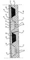
- the figure shows a vertical section through a floor.
- a floor is made up of panels 7 positioned in parallel to next to one another as well as a covering layer 8 located thereon.
- the panels 7 thus make up a formwork for the production of the covering layer 8.
- the panels 7 are fixed to one another by means of an overlap joint 9. They consist of a flat bottom outer layer 10, a profiled top outer layer 11 and a fill 12 that fills the space between the outer layers 10, 11 and joins these outer layers 10, 11 to one another.
- the fill can, for example, comprise mineral wool, PUR foam or PIR foam.
- the profiled top outer layer 11 has raised sections 13 and lowered sections 14 which define troughs between them. These troughs are made to widen from the lowered sections 14 to the raised sections 13.
- the panels 7 have high rigidity, whilst the weight thereof is relatively low. The rigidity and strength of the panels 7 are such that they are able to bear the weight of the freshly poured covering layer 8 without further support.
- the panels are first of all placed on supports and fixed to one another.
- the reinforcing bars 15 are then placed in the lowered sections 14.
- the concrete mix 16 is then poured, which is allowed to cure.
- concrete mix 16 may be poured only into the lowered sections 14 and allowed to cure to form beams 17 and the concrete mix for the covering layer 18 may then be poured with anti-crack mesh 19 therein.
- the advantage of this is that the panels 7 are subjected to less severe loading and thus can be more lightweight or can span a greater length.
- the full amount of concrete mix required for the beams 17 and the covering layer 18 is poured immediately.
- the formwork consisting of the panels 17 is releasable.
- the formwork can optionally be removed after the covering layer 8 has cured.
- the panels 17 can also be left behind, such that they form permanent formwork. In this state the panels provide supplementary protection against, for example, fire and other types of attack on the floor, such as corrosion.
- Lowered sections 14 between the beams 17 are filled with a foam material 20.
- a foam material 20 is filled with a foam material 20.
- the lower weights have a knock-on effect in the complete construction of the building, since as a result the walls and the foundation of the building can also be made more lightweight and thus less expensive.
Abstract
Description
- The invention relates to a method for the production of a building construction with the aid of formwork, comprising the following steps:
- providing a releasable formwork that comprises at least one panel consisting of a bottom outer layer and a top profiled outer layer located some distance apart as well as a fill joining the outer layers to one another,
- placing said formwork on a support, which formwork comprises a profiled formwork form with raised parts and lowered parts, said formwork having an essentially constant cross-section viewed in the longitudinal direction,
- applying a curable concrete mix on top of the formwork,
- making the concrete mix cure,
- placing reinforcement in at least one of the lowered parts of the formwork form, such that a reinforced beam is formed in said at least one lowered part of the formwork form.
- Such a method using a releasable formwork is disclosed in
NL-A-9602722 - The aim of the invention is therefore to provide a method for the production of, for example, floors which does not have this disadvantage and which can be designed in a more flexible way. Said aim is achieved by placing the reinforcement and the curable concrete mix in a series of lowered sections, each of which is alternated with lowered sections filled with another fill material and in that the bottom outer layer forms a flat plane.
- With the method according to the invention the advantage is retained that the production of the building construction can be less labour intensive because the profiled formwork has a relatively high rigidity and consequently requires little or no support between the bearing points. This means that no or hardly any props have to be positioned, as a result of which the advantage is also obtained that the space beneath the formwork remains more easily accessible.
- On the other hand, this method has the advantage that a self-supporting building construction can be produced by this means; that is to say the formwork does not have to constitute a load-bearing component of the building construction. The reinforcement that is incorporated in the lowered parts of the formwork form ensures that the beams formed in said lowered parts have adequate load-bearing capacity. After the concrete has cured the formwork itself can be removed, if desired, or left behind if this is desirable, for example in connection with fulfilling secondary functions, as will be discussed below.
- The use of a formwork with a panel made up in this way has various advantages. First of all, such a panel has an appreciably improved insulating effect that is associated with the nature of the material that has been selected for the fill. The protection against fire and against penetration can be guaranteed for a much longer period by a suitably chosen fill, such that the construction does not give way at all or gives way such that sufficient time is available for safe evacuation of the building concerned.
- A further advantage is that such a formwork can be made lightweight and is nevertheless sufficiently rigid as a consequence of the relatively high moment of inertia for the cross-section thereof. Therefore, for this reason as well no supplementary props are needed to bear the weight of reinforcement and freshly poured concrete.
- It is furthermore important that the outer layer of the formwork that is in contact with the concrete is well protected against outside influences, in particular against corrosion. In an aggressive environment it is true that the other, exposed outer layer would be able to be adversely affected in the course of time but, because the layer facing the concrete remains intact the possible reinforcing function thereof is not lost.
- As discussed, the method according to the invention is carried out using a panel with which at least one of the outside layers is profiled with raised and lowered regions. Such a panel has a relatively high moment of inertia and is used with the profiled outer layer at the top, such that this outer layer forms a formwork form.
- As mentioned, the reinforcement is placed in the lowered sections of the formwork, such that reinforced beams are formed. If the load on the floor remains limited, or the beams are sufficiently strong, beams do not have to be produced in all lowered sections of the formwork. Therefore, the reinforcement and the curable concrete mix are put into a series of lowered sections, each of which alternates with lowered sections filled with another fill material. Said other fill material can be, for example, a lightweight plastic foam.
- A method where the reinforcement is placed a distance away from the bottom of the lowered section that is less than the distance from the reinforcement to the top of the raised section is preferred. Such a position of the reinforcement, a relatively large distance away from the neutral line, offers excellent resistance to bending stresses.
- Furthermore, a continuous layer of concrete mix (compression layer) can be applied, the level of which is higher than that of the raised sections of the formwork. In this context according to an advantageous variant of the method according to the invention the concrete mix can be made to cure in the lowered sections of the formwork in order to form load-bearing beams. After forming said beams the continuous layer of concrete mix can then be poured onto said beams. The advantage of this formation of the beams and the continuous layer at different times is that the formwork only has to be geared to the loading that results from the reinforcement and the concrete mix that is used to form the beams. Since the concrete mix and the reinforcement for the continuous layer are applied only after the beams have acquired their load-bearing function, the formwork does not have to be designed for these, as a result of which it can remain relatively lightweight. This has advantageous consequences for the complete load-bearing construction of a building, since the load-bearing walls and the foundation can now also be made more lightweight. The concrete mix for the beams and for the continuous layer can, of course, also be applied and cured at the same time.
- The formwork preferably has a constant cross-section viewed in the longitudinal direction.
- The invention furthermore relates to a combination comprising a releasable formwork with an essentially constant cross-section viewed in longitudinal direction for use with the method according to one of the preceding claims, comprising a panel consisting of a bottom outer layer and a top profiled outer layer located some distance apart as well as a fill joining the outer layers to one another, wherein the top outer layer forms a formwork form with raised sections and lowered sections that define troughs between them, wherein said troughs are made to widen in the direction from the lowered sections towards the raised sections. Said combination is characterised in that the bottom outer layer forms a flat plane, in that a series of lowered sections can be filled with a curable concrete mix and in that said series of lowered sections are each alternated with lowered sections filled with a fill material not being concrete, said fill material being a part of the claimed combination.
- The fill in the panel can be made in any known manner. Preferably the fill is fire-retardant and/or thermally insulating and/or acoustically insulating.
- The invention will be explained in more detail below with reference to an illustrative embodiment shown in the figure.
- The figure shows a vertical section through a floor.
- A floor is made up of panels 7 positioned in parallel to next to one another as well as a covering
layer 8 located thereon. The panels 7 thus make up a formwork for the production of the coveringlayer 8. - The panels 7 are fixed to one another by means of an overlap joint 9. They consist of a flat bottom
outer layer 10, a profiled topouter layer 11 and a fill 12 that fills the space between theouter layers outer layers outer layer 11 has raisedsections 13 and loweredsections 14 which define troughs between them. These troughs are made to widen from the loweredsections 14 to the raisedsections 13. As a consequence of this construction the panels 7 have high rigidity, whilst the weight thereof is relatively low. The rigidity and strength of the panels 7 are such that they are able to bear the weight of the freshly poured coveringlayer 8 without further support. - In the production of the
floor 6 the panels are first of all placed on supports and fixed to one another. Thereinforcing bars 15 are then placed in the loweredsections 14. Theconcrete mix 16 is then poured, which is allowed to cure. With this procedure according to a firstoption concrete mix 16 may be poured only into the loweredsections 14 and allowed to cure to formbeams 17 and the concrete mix for the coveringlayer 18 may then be poured withanti-crack mesh 19 therein. The advantage of this is that the panels 7 are subjected to less severe loading and thus can be more lightweight or can span a greater length. According to a second option, the full amount of concrete mix required for thebeams 17 and the coveringlayer 18 is poured immediately. - As a consequence of the widening shape of the troughs between the lowered
sections 14 and the raisedsections 13, the formwork consisting of thepanels 17 is releasable. This means that the formwork can optionally be removed after the coveringlayer 8 has cured. However, thepanels 17 can also be left behind, such that they form permanent formwork. In this state the panels provide supplementary protection against, for example, fire and other types of attack on the floor, such as corrosion. - Lowered
sections 14 between thebeams 17 are filled with afoam material 20. Here as well there is the advantage of a lower weight. The lower weights have a knock-on effect in the complete construction of the building, since as a result the walls and the foundation of the building can also be made more lightweight and thus less expensive.
Claims (11)
- Method for the production of a building construction with the aid of formwork, comprising the following steps:- providing a releasable formwork that comprises at least one panel (7) consisting of a bottom outer layer (10) and a top profiled outer layer (11) located some distance apart as well as a fill (12) joining the outer layers (10, 11) to one another,- placing said formwork (7) on a support, which formwork comprises a profiled formwork form with raised parts (13) and lowered parts (14), said formwork (7) having an essentially constant cross-section viewed in the longitudinal direction,- applying a curable concrete mix (16) on top of the formwork (7),- making the concrete mix (16) cure,- placing reinforcement (15) in at least one of the lowered parts (14) of the formwork form, such that a reinforced beam is formed in said at least one lowered part (14) of the formwork form,characterised by placing the reinforcement (15) and the curable concrete mix (16) in a series of lowered sections (14), each of which is alternated with lowered sections (14) filled with another fill material (20) and in that the bottom outer layer (10) forms a flat plane.
- Method according to claim 1, comprising placing the reinforcement (15) a distance away from the bottom of the lowered section (14) that is less than the distance from the reinforcement (15) to the top of the raised section (13).
- Method according to one of the preceding claims, comprising applying a continuous layer of concrete mix (compression layer 18), the level of which is higher than that of the raised sections (13) of the formwork.
- Method according to Claim 2 or 3, comprising making the concrete mix (16) cure in lowered sections (14) of the formwork to form load-bearing beams (17) and pouring the continuous layer of concrete mix (18) onto said beams (17) after said beams (17) have been formed.
- Method according to Claim 3 or 4, comprising placing an anti-crack mesh in the top layer of concrete mix.
- Method according to one of the preceding claims, comprising the provision of a releasable formwork with an essentially smooth formwork surface.
- A combination comprising a releasable formwork with an essentially constant cross-section viewed in longitudinal direction for use with the method according to one of the preceding claims, comprising a panel (7) consisting of a bottom outer layer (10) and a top profiled outer layer (11) located some distance apart as well as a fill (12) joining the outer layers (10, 11) to one another, wherein the top outer layer (11) forms a formwork form with raised sections (13) and lowered sections (14) that define troughs between them, wherein said troughs are made to widen in the direction from the lowered sections (14) towards the raised sections (13), characterised in that the bottom outer layer forms a flat plane, in that a series of lowered sections (14) can be filled with a curable concrete mix, and in that said series of lowered sections (14) are each alternated with lowered sections filled with a fill material not being concrete, said fill material being a part of the claimed combination.
- Combination according to Claim 7, wherein the fill (12) is thermally insulating.
- Combination according to one of Claims 7 or 8, wherein the fill (12) is acoustically insulating.
- Combination according to one of Claims 7-9, wherein the fill (12) is fire-retardant.
- Combination according to one of Claims 7-10, wherein the surface of the form is smooth.
Applications Claiming Priority (2)
| Application Number | Priority Date | Filing Date | Title |
|---|---|---|---|
| NL1026388 | 2004-06-11 | ||
| NL1026388A NL1026388C2 (en) | 2004-06-11 | 2004-06-11 | Method for manufacturing a building construction, as well as formwork therefor. |
Publications (2)
| Publication Number | Publication Date |
|---|---|
| EP1605112A1 EP1605112A1 (en) | 2005-12-14 |
| EP1605112B1 true EP1605112B1 (en) | 2009-12-16 |
Family
ID=34940151
Family Applications (1)
| Application Number | Title | Priority Date | Filing Date |
|---|---|---|---|
| EP05105157A Active EP1605112B1 (en) | 2004-06-11 | 2005-06-13 | Method for the production of a building construction as well as formwork therefor |
Country Status (7)
| Country | Link |
|---|---|
| US (1) | US7845138B2 (en) |
| EP (1) | EP1605112B1 (en) |
| AT (1) | ATE452253T1 (en) |
| DE (1) | DE602005018289D1 (en) |
| DK (1) | DK1605112T3 (en) |
| ES (1) | ES2338795T3 (en) |
| NL (1) | NL1026388C2 (en) |
Families Citing this family (9)
| Publication number | Priority date | Publication date | Assignee | Title |
|---|---|---|---|---|
| US8234827B1 (en) * | 2005-09-01 | 2012-08-07 | Schroeder Sr Robert | Express framing building construction system |
| US7871055B1 (en) * | 2006-04-24 | 2011-01-18 | University Of Maine System Board Of Trustees | Lightweight composite concrete formwork panel |
| WO2008041251A1 (en) * | 2006-10-05 | 2008-04-10 | Metecno S.P.A. | Building floor structure and method for laying down thereof |
| US8205412B2 (en) * | 2008-01-24 | 2012-06-26 | Consolidated Systems, Inc. | Panelization method and system |
| US8505599B2 (en) * | 2008-01-24 | 2013-08-13 | Consolidated Systems, Inc. | Panelization system and method |
| PL2686500T3 (en) * | 2011-03-18 | 2019-01-31 | Peter Mervyn NEIL | Composite wall panel, wall system and components thereof, and a method of construction thereof |
| US20120297701A1 (en) * | 2011-05-27 | 2012-11-29 | Gerard Oakley | Folded cardboard concrete form system |
| JP6459118B2 (en) * | 2014-09-25 | 2019-01-30 | 株式会社ピーエス三菱 | Precast concrete plate with ribs for synthetic floor slab |
| CN106013567A (en) * | 2016-06-08 | 2016-10-12 | 湖南标迪夫节能科技有限公司 | Fabricated stressed island reinforced concrete cavity floor system |
Citations (11)
| Publication number | Priority date | Publication date | Assignee | Title |
|---|---|---|---|---|
| US1068544A (en) * | 1912-11-05 | 1913-07-29 | Perez M Stewart | Building construction. |
| NL6902722A (en) * | 1969-02-21 | 1970-08-25 | ||
| US3595515A (en) * | 1968-09-13 | 1971-07-27 | William B Rollow | Laminated concrete form |
| BE824725A (en) * | 1975-01-24 | 1975-05-15 | METAL FLOOR | |
| US3884008A (en) * | 1973-08-24 | 1975-05-20 | Herman C Miller | Concrete insert |
| BE835641A (en) * | 1975-11-17 | 1976-03-16 | FLOOR SHEATH OR LOST METAL FORMWORK FOR CONCRETE SLAB, HOURDIS | |
| US4003542A (en) * | 1975-09-22 | 1977-01-18 | Beer Issie M | Form pans for constructing ribbed slab structures |
| EP0331583A1 (en) * | 1988-03-04 | 1989-09-06 | Jean-Marie Edouard Vuillermoz | Devices for making recesses in concrete |
| EP1327732A1 (en) * | 2001-12-24 | 2003-07-16 | System Albanese | Edge shuttering for concrete slabs |
| EP1350898A1 (en) * | 2000-05-16 | 2003-10-08 | Jaime Enrique Jimenez Sanchez | Process for fabricating in situ a light alveolar plate, plate thus obtained and its application to the construction of houses |
| ES1055224U (en) * | 2003-06-19 | 2003-11-01 | Prefabricados Castelo S A | Prefabricated wrought up to construction sites. (Machine-translation by Google Translate, not legally binding) |
Family Cites Families (23)
| Publication number | Priority date | Publication date | Assignee | Title |
|---|---|---|---|---|
| US1925229A (en) * | 1931-07-18 | 1933-09-05 | Brunle Jacob | Concrete floor construction and mold therefor |
| GB857249A (en) * | 1956-11-30 | 1960-12-29 | Serge Desire Auguste Dieulanga | Improvements in heat-exchange ceilings for buildings |
| NL277568A (en) | 1962-01-29 | 1964-11-10 | ||
| NL147819B (en) | 1970-09-04 | 1975-11-17 | Hollandse Bouwcombinatie Holla | PROFILED FLOOR PLATE, AS WELL AS CASTED CONCRETE FLOOR IN IT. |
| AT309778B (en) * | 1970-10-13 | 1973-09-10 | Leo Kilian Ing | Formwork panel |
| FR2143603B1 (en) * | 1971-07-01 | 1974-08-19 | Raoult Andre | |
| BE786543A (en) * | 1971-07-22 | 1973-01-22 | Williams Geoffrey M J C O Scot | PERFECTED PROCESS FOR THE MANUFACTURE OF CONCRETE STRUCTURES |
| CA1181215A (en) * | 1981-02-04 | 1985-01-22 | Wolfgang Radtke | Hollow floor |
| US4747247A (en) * | 1986-09-19 | 1988-05-31 | The Dow Chemical Company | Roof system |
| NO874020D0 (en) * | 1987-09-24 | 1987-09-24 | Selvaagebygg As | FLOOR CONSTRUCTION AND ELEMENT FOR SUCH, AND PROCEDURE FOR THIS MANUFACTURING. |
| NL8800611A (en) * | 1988-03-11 | 1989-10-02 | Stichting Istaned | COMPOSITE FLOOR CONSTRUCTION AND METHOD FOR MANUFACTURING THAT. |
| US4809474A (en) * | 1988-04-01 | 1989-03-07 | Iowa State University Research Foundation, Inc. | Prestressed composite floor slab and method of making the same |
| ES2109684T3 (en) * | 1994-03-10 | 1998-01-16 | Jorgen Lassen | ELEMENT INTENDED FOR THE MANUFACTURE OF A REINFORCED CONCRETE STRUCTURE PROVIDED WITH CAVES, FILLING BODY INTENDED FOR THE MANUFACTURE OF THIS ELEMENT, AND THE PROCESS FOR THE MANUFACTURE OF A REINFORCED CONCRETE STRUCTURE PROVIDED WITH CAVITIES. |
| SE506735C2 (en) * | 1994-07-13 | 1998-02-02 | Plannja Ab | Collaboration joists, in which a sandwich element was used as a lost form |
| DE4435895C2 (en) * | 1994-10-07 | 2001-09-20 | Freudenberg Carl Fa | Raised floor |
| IT1282153B1 (en) * | 1995-05-05 | 1998-03-16 | Metecno Spa | DEEP THERMAL INSULATION COMPOSITE PANEL |
| SE504954C2 (en) * | 1995-09-08 | 1997-06-02 | Legalett International Ab | When casting concrete floor tiles and intermediate joists |
| US5934036A (en) * | 1996-11-01 | 1999-08-10 | Gallagher, Jr.; Daniel P. | Insulated concrete slab assembly |
| DE10052800C1 (en) * | 2000-10-25 | 2002-08-29 | Thyssenkrupp Stahl Ag | roof element |
| FI119604B (en) * | 2001-05-16 | 2009-01-15 | Rautaruukki Oyj | Load-bearing composite slab for buildings |
| US6702510B2 (en) * | 2002-01-03 | 2004-03-09 | Ede Holdings, Inc. | Utility sidewalk |
| US7100336B2 (en) * | 2002-03-06 | 2006-09-05 | Oldcastle Precast, Inc. | Concrete building panel with a low density core and carbon fiber and steel reinforcement |
| US7601234B2 (en) * | 2005-06-15 | 2009-10-13 | Panterra Engineered Plastics, Inc. | Housing created from high strength expanded thermoformable honeycomb structures with cementitious reinforcement |
-
2004
- 2004-06-11 NL NL1026388A patent/NL1026388C2/en not_active IP Right Cessation
-
2005
- 2005-06-13 AT AT05105157T patent/ATE452253T1/en not_active IP Right Cessation
- 2005-06-13 US US11/151,636 patent/US7845138B2/en not_active Expired - Fee Related
- 2005-06-13 EP EP05105157A patent/EP1605112B1/en active Active
- 2005-06-13 DK DK05105157.1T patent/DK1605112T3/en active
- 2005-06-13 DE DE602005018289T patent/DE602005018289D1/en active Active
- 2005-06-13 ES ES05105157T patent/ES2338795T3/en active Active
Patent Citations (11)
| Publication number | Priority date | Publication date | Assignee | Title |
|---|---|---|---|---|
| US1068544A (en) * | 1912-11-05 | 1913-07-29 | Perez M Stewart | Building construction. |
| US3595515A (en) * | 1968-09-13 | 1971-07-27 | William B Rollow | Laminated concrete form |
| NL6902722A (en) * | 1969-02-21 | 1970-08-25 | ||
| US3884008A (en) * | 1973-08-24 | 1975-05-20 | Herman C Miller | Concrete insert |
| BE824725A (en) * | 1975-01-24 | 1975-05-15 | METAL FLOOR | |
| US4003542A (en) * | 1975-09-22 | 1977-01-18 | Beer Issie M | Form pans for constructing ribbed slab structures |
| BE835641A (en) * | 1975-11-17 | 1976-03-16 | FLOOR SHEATH OR LOST METAL FORMWORK FOR CONCRETE SLAB, HOURDIS | |
| EP0331583A1 (en) * | 1988-03-04 | 1989-09-06 | Jean-Marie Edouard Vuillermoz | Devices for making recesses in concrete |
| EP1350898A1 (en) * | 2000-05-16 | 2003-10-08 | Jaime Enrique Jimenez Sanchez | Process for fabricating in situ a light alveolar plate, plate thus obtained and its application to the construction of houses |
| EP1327732A1 (en) * | 2001-12-24 | 2003-07-16 | System Albanese | Edge shuttering for concrete slabs |
| ES1055224U (en) * | 2003-06-19 | 2003-11-01 | Prefabricados Castelo S A | Prefabricated wrought up to construction sites. (Machine-translation by Google Translate, not legally binding) |
Also Published As
| Publication number | Publication date |
|---|---|
| DE602005018289D1 (en) | 2010-01-28 |
| US7845138B2 (en) | 2010-12-07 |
| ATE452253T1 (en) | 2010-01-15 |
| NL1026388C2 (en) | 2005-12-15 |
| ES2338795T3 (en) | 2010-05-12 |
| EP1605112A1 (en) | 2005-12-14 |
| DK1605112T3 (en) | 2010-05-03 |
| US20050284089A1 (en) | 2005-12-29 |
Similar Documents
| Publication | Publication Date | Title |
|---|---|---|
| EP1605112B1 (en) | Method for the production of a building construction as well as formwork therefor | |
| EP1192321B1 (en) | Integral concrete wall forming panel and method | |
| US20090113820A1 (en) | Prefabricated wall panel system | |
| EP2739799B1 (en) | Building structure of pre-cast monolithic walls and interfloor slabs | |
| US20100088986A1 (en) | Method of constructing a building, such building, and wall and floor elements for use therein | |
| EP3115523B1 (en) | Concrete panel, especially for composite floors, and a composite floor | |
| JP5314356B2 (en) | Composite beam, composite beam construction method, and fireproof building | |
| US3956859A (en) | Foundation of a heated building without a cellar | |
| RU2012117792A (en) | PRELIMINARY FABRIC PANEL INTENDED FOR INSTALLATION IN A HORIZONTAL OR VERTICAL, TILTED STATE | |
| KR101633301B1 (en) | Method for producing a concrete component, prefabricated structural element of a concrete component, and concrete component | |
| US20090255199A1 (en) | Concrete Floor System Incorporating Foundation Footing | |
| EP3594425B1 (en) | A load-bearing wall structure | |
| CN107237448A (en) | A kind of prefabricated interior fill concrete wallboard and its manufacture method | |
| FI119604B (en) | Load-bearing composite slab for buildings | |
| EP2886733A1 (en) | A method for assembling and the construction of a plane or inclined floor for residential and industrial use, with unidirectional or bidirectional reinforcement, and means for its implementation | |
| WO2016051258A1 (en) | Prefabricated monobloc panel | |
| EP3719229B1 (en) | Concrete floor panel, method of production of such panel and floor made of this panel | |
| NL2009796C2 (en) | Building element for forming a wall of a building. | |
| CN201991068U (en) | Multi-storey building system with moulding board-clamping frame-type corewall self-supporting structure | |
| RU76656U1 (en) | COMMUNICATED PLATE-SPACER (OPTIONS), ASSEMBLY UNIT FOR COMMUNICATED PLATE-SPACERS (OPTIONS) AND FRAMED-COMMUNICATED OR COMMUNICATED MOBILE PLATFORM | |
| CZ2009113A3 (en) | Composite structural element, especially for building construction | |
| WO2007012863A1 (en) | Building panels and construction of buildings with such panels | |
| JPH08232380A (en) | Binding member between steel member and reinforced concrete and monocoque structural panel using the binding member and building under monocoque structure | |
| KR101773565B1 (en) | Underground structure using c.i.p. structure | |
| AU772991B2 (en) | Integral concrete wall forming system |
Legal Events
| Date | Code | Title | Description |
|---|---|---|---|
| PUAI | Public reference made under article 153(3) epc to a published international application that has entered the european phase |
Free format text: ORIGINAL CODE: 0009012 |
|
| AK | Designated contracting states |
Kind code of ref document: A1 Designated state(s): AT BE BG CH CY CZ DE DK EE ES FI FR GB GR HU IE IS IT LI LT LU MC NL PL PT RO SE SI SK TR |
|
| AX | Request for extension of the european patent |
Extension state: AL BA HR LV MK YU |
|
| 17P | Request for examination filed |
Effective date: 20060215 |
|
| AKX | Designation fees paid |
Designated state(s): AT BE BG CH CY CZ DE DK EE ES FI FR GB GR HU IE IS IT LI LT LU MC NL PL PT RO SE SI SK TR |
|
| AXX | Extension fees paid |
Extension state: LV Payment date: 20060215 |
|
| 17Q | First examination report despatched |
Effective date: 20060726 |
|
| 17Q | First examination report despatched |
Effective date: 20060726 |
|
| RAP1 | Party data changed (applicant data changed or rights of an application transferred) |
Owner name: OP-DECK HOLDING B.V. |
|
| GRAP | Despatch of communication of intention to grant a patent |
Free format text: ORIGINAL CODE: EPIDOSNIGR1 |
|
| GRAS | Grant fee paid |
Free format text: ORIGINAL CODE: EPIDOSNIGR3 |
|
| GRAA | (expected) grant |
Free format text: ORIGINAL CODE: 0009210 |
|
| AK | Designated contracting states |
Kind code of ref document: B1 Designated state(s): AT BE BG CH CY CZ DE DK EE ES FI FR GB GR HU IE IS IT LI LT LU MC NL PL PT RO SE SI SK TR |
|
| AX | Request for extension of the european patent |
Extension state: LV |
|
| REG | Reference to a national code |
Ref country code: GB Ref legal event code: FG4D |
|
| REG | Reference to a national code |
Ref country code: CH Ref legal event code: EP |
|
| REG | Reference to a national code |
Ref country code: IE Ref legal event code: FG4D |
|
| REF | Corresponds to: |
Ref document number: 602005018289 Country of ref document: DE Date of ref document: 20100128 Kind code of ref document: P |
|
| REG | Reference to a national code |
Ref country code: NL Ref legal event code: T3 |
|
| PG25 | Lapsed in a contracting state [announced via postgrant information from national office to epo] |
Ref country code: LT Free format text: LAPSE BECAUSE OF FAILURE TO SUBMIT A TRANSLATION OF THE DESCRIPTION OR TO PAY THE FEE WITHIN THE PRESCRIBED TIME-LIMIT Effective date: 20091216 Ref country code: SE Free format text: LAPSE BECAUSE OF FAILURE TO SUBMIT A TRANSLATION OF THE DESCRIPTION OR TO PAY THE FEE WITHIN THE PRESCRIBED TIME-LIMIT Effective date: 20091216 Ref country code: FI Free format text: LAPSE BECAUSE OF FAILURE TO SUBMIT A TRANSLATION OF THE DESCRIPTION OR TO PAY THE FEE WITHIN THE PRESCRIBED TIME-LIMIT Effective date: 20091216 |
|
| REG | Reference to a national code |
Ref country code: DK Ref legal event code: T3 |
|
| REG | Reference to a national code |
Ref country code: ES Ref legal event code: FG2A Ref document number: 2338795 Country of ref document: ES Kind code of ref document: T3 |
|
| LTIE | Lt: invalidation of european patent or patent extension |
Effective date: 20091216 |
|
| PG25 | Lapsed in a contracting state [announced via postgrant information from national office to epo] |
Ref country code: PL Free format text: LAPSE BECAUSE OF FAILURE TO SUBMIT A TRANSLATION OF THE DESCRIPTION OR TO PAY THE FEE WITHIN THE PRESCRIBED TIME-LIMIT Effective date: 20091216 Ref country code: SI Free format text: LAPSE BECAUSE OF FAILURE TO SUBMIT A TRANSLATION OF THE DESCRIPTION OR TO PAY THE FEE WITHIN THE PRESCRIBED TIME-LIMIT Effective date: 20091216 |
|
| PG25 | Lapsed in a contracting state [announced via postgrant information from national office to epo] |
Ref country code: AT Free format text: LAPSE BECAUSE OF FAILURE TO SUBMIT A TRANSLATION OF THE DESCRIPTION OR TO PAY THE FEE WITHIN THE PRESCRIBED TIME-LIMIT Effective date: 20091216 |
|
| PG25 | Lapsed in a contracting state [announced via postgrant information from national office to epo] |
Ref country code: RO Free format text: LAPSE BECAUSE OF FAILURE TO SUBMIT A TRANSLATION OF THE DESCRIPTION OR TO PAY THE FEE WITHIN THE PRESCRIBED TIME-LIMIT Effective date: 20091216 Ref country code: BG Free format text: LAPSE BECAUSE OF FAILURE TO SUBMIT A TRANSLATION OF THE DESCRIPTION OR TO PAY THE FEE WITHIN THE PRESCRIBED TIME-LIMIT Effective date: 20100316 Ref country code: EE Free format text: LAPSE BECAUSE OF FAILURE TO SUBMIT A TRANSLATION OF THE DESCRIPTION OR TO PAY THE FEE WITHIN THE PRESCRIBED TIME-LIMIT Effective date: 20091216 Ref country code: IS Free format text: LAPSE BECAUSE OF FAILURE TO SUBMIT A TRANSLATION OF THE DESCRIPTION OR TO PAY THE FEE WITHIN THE PRESCRIBED TIME-LIMIT Effective date: 20100416 Ref country code: PT Free format text: LAPSE BECAUSE OF FAILURE TO SUBMIT A TRANSLATION OF THE DESCRIPTION OR TO PAY THE FEE WITHIN THE PRESCRIBED TIME-LIMIT Effective date: 20100416 |
|
| PG25 | Lapsed in a contracting state [announced via postgrant information from national office to epo] |
Ref country code: SK Free format text: LAPSE BECAUSE OF FAILURE TO SUBMIT A TRANSLATION OF THE DESCRIPTION OR TO PAY THE FEE WITHIN THE PRESCRIBED TIME-LIMIT Effective date: 20091216 Ref country code: CZ Free format text: LAPSE BECAUSE OF FAILURE TO SUBMIT A TRANSLATION OF THE DESCRIPTION OR TO PAY THE FEE WITHIN THE PRESCRIBED TIME-LIMIT Effective date: 20091216 |
|
| PLBE | No opposition filed within time limit |
Free format text: ORIGINAL CODE: 0009261 |
|
| STAA | Information on the status of an ep patent application or granted ep patent |
Free format text: STATUS: NO OPPOSITION FILED WITHIN TIME LIMIT |
|
| PG25 | Lapsed in a contracting state [announced via postgrant information from national office to epo] |
Ref country code: CY Free format text: LAPSE BECAUSE OF FAILURE TO SUBMIT A TRANSLATION OF THE DESCRIPTION OR TO PAY THE FEE WITHIN THE PRESCRIBED TIME-LIMIT Effective date: 20091216 Ref country code: GR Free format text: LAPSE BECAUSE OF FAILURE TO SUBMIT A TRANSLATION OF THE DESCRIPTION OR TO PAY THE FEE WITHIN THE PRESCRIBED TIME-LIMIT Effective date: 20100317 |
|
| 26N | No opposition filed |
Effective date: 20100917 |
|
| PG25 | Lapsed in a contracting state [announced via postgrant information from national office to epo] |
Ref country code: IT Free format text: LAPSE BECAUSE OF FAILURE TO SUBMIT A TRANSLATION OF THE DESCRIPTION OR TO PAY THE FEE WITHIN THE PRESCRIBED TIME-LIMIT Effective date: 20091216 |
|
| PG25 | Lapsed in a contracting state [announced via postgrant information from national office to epo] |
Ref country code: LU Free format text: LAPSE BECAUSE OF NON-PAYMENT OF DUE FEES Effective date: 20100613 Ref country code: HU Free format text: LAPSE BECAUSE OF FAILURE TO SUBMIT A TRANSLATION OF THE DESCRIPTION OR TO PAY THE FEE WITHIN THE PRESCRIBED TIME-LIMIT Effective date: 20100617 |
|
| PG25 | Lapsed in a contracting state [announced via postgrant information from national office to epo] |
Ref country code: TR Free format text: LAPSE BECAUSE OF FAILURE TO SUBMIT A TRANSLATION OF THE DESCRIPTION OR TO PAY THE FEE WITHIN THE PRESCRIBED TIME-LIMIT Effective date: 20091216 |
|
| PGFP | Annual fee paid to national office [announced via postgrant information from national office to epo] |
Ref country code: MC Payment date: 20141224 Year of fee payment: 10 Ref country code: CH Payment date: 20141222 Year of fee payment: 10 Ref country code: IE Payment date: 20141222 Year of fee payment: 10 Ref country code: ES Payment date: 20141224 Year of fee payment: 10 |
|
| REG | Reference to a national code |
Ref country code: FR Ref legal event code: PLFP Year of fee payment: 11 |
|
| PG25 | Lapsed in a contracting state [announced via postgrant information from national office to epo] |
Ref country code: MC Free format text: LAPSE BECAUSE OF NON-PAYMENT OF DUE FEES Effective date: 20150630 |
|
| PGFP | Annual fee paid to national office [announced via postgrant information from national office to epo] |
Ref country code: GB Payment date: 20151231 Year of fee payment: 11 |
|
| REG | Reference to a national code |
Ref country code: CH Ref legal event code: PL |
|
| PGFP | Annual fee paid to national office [announced via postgrant information from national office to epo] |
Ref country code: FR Payment date: 20151230 Year of fee payment: 11 |
|
| REG | Reference to a national code |
Ref country code: IE Ref legal event code: MM4A |
|
| PG25 | Lapsed in a contracting state [announced via postgrant information from national office to epo] |
Ref country code: IE Free format text: LAPSE BECAUSE OF NON-PAYMENT OF DUE FEES Effective date: 20150613 Ref country code: LI Free format text: LAPSE BECAUSE OF NON-PAYMENT OF DUE FEES Effective date: 20150630 Ref country code: CH Free format text: LAPSE BECAUSE OF NON-PAYMENT OF DUE FEES Effective date: 20150630 |
|
| PGFP | Annual fee paid to national office [announced via postgrant information from national office to epo] |
Ref country code: DE Payment date: 20151231 Year of fee payment: 11 |
|
| PGFP | Annual fee paid to national office [announced via postgrant information from national office to epo] |
Ref country code: BE Payment date: 20151231 Year of fee payment: 11 |
|
| REG | Reference to a national code |
Ref country code: ES Ref legal event code: FD2A Effective date: 20160727 |
|
| PG25 | Lapsed in a contracting state [announced via postgrant information from national office to epo] |
Ref country code: ES Free format text: LAPSE BECAUSE OF NON-PAYMENT OF DUE FEES Effective date: 20150614 |
|
| PG25 | Lapsed in a contracting state [announced via postgrant information from national office to epo] |
Ref country code: BE Free format text: LAPSE BECAUSE OF NON-PAYMENT OF DUE FEES Effective date: 20160630 |
|
| REG | Reference to a national code |
Ref country code: DE Ref legal event code: R119 Ref document number: 602005018289 Country of ref document: DE |
|
| GBPC | Gb: european patent ceased through non-payment of renewal fee |
Effective date: 20160613 |
|
| REG | Reference to a national code |
Ref country code: FR Ref legal event code: ST Effective date: 20170228 |
|
| PG25 | Lapsed in a contracting state [announced via postgrant information from national office to epo] |
Ref country code: FR Free format text: LAPSE BECAUSE OF NON-PAYMENT OF DUE FEES Effective date: 20160630 Ref country code: DE Free format text: LAPSE BECAUSE OF NON-PAYMENT OF DUE FEES Effective date: 20170103 |
|
| PG25 | Lapsed in a contracting state [announced via postgrant information from national office to epo] |
Ref country code: GB Free format text: LAPSE BECAUSE OF NON-PAYMENT OF DUE FEES Effective date: 20160613 |
|
| REG | Reference to a national code |
Ref country code: NL Ref legal event code: PD Owner name: REPPEL B.V.; NL Free format text: DETAILS ASSIGNMENT: CHANGE OF OWNER(S), ASSIGNMENT; FORMER OWNER NAME: OP-DECK HOLDING B.V. Effective date: 20201001 |
|
| PGFP | Annual fee paid to national office [announced via postgrant information from national office to epo] |
Ref country code: NL Payment date: 20230307 Year of fee payment: 19 |
|
| PGFP | Annual fee paid to national office [announced via postgrant information from national office to epo] |
Ref country code: DK Payment date: 20230621 Year of fee payment: 19 |