EP1602846A1 - Kupplungsanordnung - Google Patents
Kupplungsanordnung Download PDFInfo
- Publication number
- EP1602846A1 EP1602846A1 EP04012868A EP04012868A EP1602846A1 EP 1602846 A1 EP1602846 A1 EP 1602846A1 EP 04012868 A EP04012868 A EP 04012868A EP 04012868 A EP04012868 A EP 04012868A EP 1602846 A1 EP1602846 A1 EP 1602846A1
- Authority
- EP
- European Patent Office
- Prior art keywords
- clutch
- actuating
- coupling arrangement
- arrangement according
- lever
- Prior art date
- Legal status (The legal status is an assumption and is not a legal conclusion. Google has not performed a legal analysis and makes no representation as to the accuracy of the status listed.)
- Granted
Links
- 230000008878 coupling Effects 0.000 claims description 47
- 238000010168 coupling process Methods 0.000 claims description 47
- 238000005859 coupling reaction Methods 0.000 claims description 47
- 239000011324 bead Substances 0.000 claims description 2
- 230000005540 biological transmission Effects 0.000 description 18
- 239000007787 solid Substances 0.000 description 6
- 210000003127 knee Anatomy 0.000 description 4
- 238000006243 chemical reaction Methods 0.000 description 3
- 238000006073 displacement reaction Methods 0.000 description 3
- 238000007789 sealing Methods 0.000 description 3
- 230000035945 sensitivity Effects 0.000 description 3
- 241000446313 Lamella Species 0.000 description 2
- 238000010276 construction Methods 0.000 description 2
- 238000005452 bending Methods 0.000 description 1
- 239000000969 carrier Substances 0.000 description 1
- 238000002485 combustion reaction Methods 0.000 description 1
- 230000001419 dependent effect Effects 0.000 description 1
- 230000000694 effects Effects 0.000 description 1
- 238000009434 installation Methods 0.000 description 1
- 239000000463 material Substances 0.000 description 1
- 238000004080 punching Methods 0.000 description 1
Images

Classifications
-
- F—MECHANICAL ENGINEERING; LIGHTING; HEATING; WEAPONS; BLASTING
- F16—ENGINEERING ELEMENTS AND UNITS; GENERAL MEASURES FOR PRODUCING AND MAINTAINING EFFECTIVE FUNCTIONING OF MACHINES OR INSTALLATIONS; THERMAL INSULATION IN GENERAL
- F16D—COUPLINGS FOR TRANSMITTING ROTATION; CLUTCHES; BRAKES
- F16D25/00—Fluid-actuated clutches
- F16D25/06—Fluid-actuated clutches in which the fluid actuates a piston incorporated in, i.e. rotating with the clutch
- F16D25/062—Fluid-actuated clutches in which the fluid actuates a piston incorporated in, i.e. rotating with the clutch the clutch having friction surfaces
- F16D25/063—Fluid-actuated clutches in which the fluid actuates a piston incorporated in, i.e. rotating with the clutch the clutch having friction surfaces with clutch members exclusively moving axially
- F16D25/0635—Fluid-actuated clutches in which the fluid actuates a piston incorporated in, i.e. rotating with the clutch the clutch having friction surfaces with clutch members exclusively moving axially with flat friction surfaces, e.g. discs
- F16D25/0638—Fluid-actuated clutches in which the fluid actuates a piston incorporated in, i.e. rotating with the clutch the clutch having friction surfaces with clutch members exclusively moving axially with flat friction surfaces, e.g. discs with more than two discs, e.g. multiple lamellae
-
- F—MECHANICAL ENGINEERING; LIGHTING; HEATING; WEAPONS; BLASTING
- F16—ENGINEERING ELEMENTS AND UNITS; GENERAL MEASURES FOR PRODUCING AND MAINTAINING EFFECTIVE FUNCTIONING OF MACHINES OR INSTALLATIONS; THERMAL INSULATION IN GENERAL
- F16D—COUPLINGS FOR TRANSMITTING ROTATION; CLUTCHES; BRAKES
- F16D21/00—Systems comprising a plurality of actuated clutches
- F16D21/02—Systems comprising a plurality of actuated clutches for interconnecting three or more shafts or other transmission members in different ways
- F16D21/06—Systems comprising a plurality of actuated clutches for interconnecting three or more shafts or other transmission members in different ways at least two driving shafts or two driven shafts being concentric
-
- F—MECHANICAL ENGINEERING; LIGHTING; HEATING; WEAPONS; BLASTING
- F16—ENGINEERING ELEMENTS AND UNITS; GENERAL MEASURES FOR PRODUCING AND MAINTAINING EFFECTIVE FUNCTIONING OF MACHINES OR INSTALLATIONS; THERMAL INSULATION IN GENERAL
- F16D—COUPLINGS FOR TRANSMITTING ROTATION; CLUTCHES; BRAKES
- F16D25/00—Fluid-actuated clutches
- F16D25/10—Clutch systems with a plurality of fluid-actuated clutches
-
- F—MECHANICAL ENGINEERING; LIGHTING; HEATING; WEAPONS; BLASTING
- F16—ENGINEERING ELEMENTS AND UNITS; GENERAL MEASURES FOR PRODUCING AND MAINTAINING EFFECTIVE FUNCTIONING OF MACHINES OR INSTALLATIONS; THERMAL INSULATION IN GENERAL
- F16D—COUPLINGS FOR TRANSMITTING ROTATION; CLUTCHES; BRAKES
- F16D21/00—Systems comprising a plurality of actuated clutches
- F16D21/02—Systems comprising a plurality of actuated clutches for interconnecting three or more shafts or other transmission members in different ways
- F16D21/06—Systems comprising a plurality of actuated clutches for interconnecting three or more shafts or other transmission members in different ways at least two driving shafts or two driven shafts being concentric
- F16D2021/0661—Hydraulically actuated multiple lamellae clutches
Definitions
- the invention relates to a coupling arrangement according to the preamble of claim 1.
- Each coupling has an outer plate carrier with outer plates and an inner disk carrier with inner disks.
- the Slats are in their respective carrier in axially extending Guided grooves, so that an axial displacement of the slats given is.
- the torque transmission from the plate carrier to the slat takes place positively.
- an axial force is exerted on the lamellae, so that the Slats are pressed against an end stop. hereby the clutch is closed.
- the power to adjust the Piston is usually by means of a pressure medium on the Transfer piston.
- the clutch opens when the force effect the pressure medium is eliminated.
- the piston is moved by the return element pushed back to its original position.
- a generic coupling arrangement is for example EP 0 758 434 B1.
- the actuating piston space of the first clutch is formed from the outer disk carrier of the first clutch and the Piston of the first clutch.
- the transmission of the actuating force on the disk pack is done directly by pressing the Piston to the disk pack.
- An indirect power transmission the actuating force from the piston to the disk pack is with the known coupling arrangement not possible.
- the invention is based on the object, a clutch assembly to provide greater variability in which by simple constructive measures an indirect introduction of force from the piston in the disk set is possible.
- the actuating piston space the first clutch is formed from the Actuating piston of the first clutch and the outer disk carrier the second clutch and / or the actuating piston space the second clutch is formed of a disc and the Actuating piston of the second clutch.
- the inventive Coupling arrangement is the actuating direction of the actuating piston the actuating direction of the piston in the off opposite to the prior art multi-plate clutch.
- At least one coupling preferably both couplings have a compensation chamber, about the change of the pressing force of the actuating piston is counteracted due to the rotational movement of the clutch.
- the additional axial force is compensated, in which the compensation chamber pressurized medium is applied. This results a force that is about the same size as the extra one Axial force and its direction of the direction of the additional Counteracts axial force.
- Clutch assembly are required by the fact that the Compensation space of the first clutch is formed from the outer disk carrier the first clutch and the actuating piston the first clutch and / or the fact that the compensation chamber the second clutch is formed from the outer disk carrier the second clutch and the actuating piston of the second Clutch.
- the outer and / or the inner actuating lever are formed as, preferably two-armed, reversing lever, wherein preferably the direction of the force exerted by the reversing lever on the blades force, the direction of the introduced into the lever actuating force of the actuating piston opposite is.
- the reversing lever is preferably designed as a two-armed toggle lever, wherein the lever is mounted on his knee. The elasticity of the reversing lever allows a soft moment structure.
- the first time to vary the contact pressure by a change in the lever ratio L 2 / L 1 at a constant operating pressure and constant actuating piston surfaces.
- the range of application of the clutch is extended to different torque ranges.
- the basic coupling structure remain essentially the same, it must only be selected a different lever ratio.
- the reaction sensitivity of the clutch is adjustable via the choice of the lever ratio. The longer the piston-side arm of the reversing lever is configured, the less sensitive the clutch works. In the opposite case, the sensitivity is significantly increased.
- the outer actuating lever and / or the inner operating levers by one, preferably closed ring connected together. hereby the installation of the bell crank mechanism in the clutch assembly much easier.
- the return elements act for moving the piston to its initial position not directly on the piston, but on the lever and only this acts on the piston.
- restoring elements Provide disc springs. These are in the prior art integrated as independent components in the coupling. According to the invention is provided with advantage that the ring with the Levers as restoring element, in particular as disc spring, is trained. This eliminates the return element as separate component.
- both means are by means of tabs formed, which engage between the bell crank of the rings.
- the tabs for securing and centering of the outer ring provided with advantage on the outer plate carrier.
- the tabs for securing and centering the inner ring are located on the inner disk carrier. For example, all tabs can by punching and bending out of the plate carriers be formed.
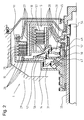
- FIG. 1 illustrates schematically a detail from an exemplarily selected powertrain for a motor vehicle a possible basic structure and functioning an inventively designed clutch assembly.
- crankshaft 2 indicated which, for example, with an internal combustion engine or the like is coupled. This page represents the drive side of the drive train.
- the crankshaft 2 has a coupling end 3 for coupling a not shown torsional vibration damper.
- a coupling end 3 for coupling a not shown torsional vibration damper.
- the crankshaft 2 has a coupling end 3 for coupling a not shown torsional vibration damper.
- In the Drawing are two coaxial arranged to the left Transmission hollow shafts 4, 5 shown, which in turn coaxially a central solid shaft 6 are arranged.
- a pump drive shaft At the central Solid shaft 6 is a pump drive shaft, the for driving a transmission-side, not shown oil pump serves.
- electric motor driven oil pump can be dispensed with the pump drive shaft 6 be, or the pump drive shaft 6 can be used as a transmission input shaft be designed.
- the clutch assembly is in a gear housing bell 7 taken, with the bell interior towards the drive side is closed by a lid 8, which on Bell housing 7 is secured by a snap ring 9.
- Coupling input side is a coupled to the crankshaft 2, integrally formed clutch hub 10 is provided.
- the clutch hub 10 penetrates a central opening of the lid 8 and is opposite the cover 8 by a ring seal 11 sealed.
- the pump drive shaft 6 is via a corresponding toothing 12 positively with the clutch hub 10 and thus with the crankshaft 2 connected.
- the clutch hub 10 is rotationally fixed with an outer drive plate 13 connected. About the outer drive plate 13 is the input torque from the clutch hub 10 to an outer disc carrier 14 a first clutch 15 transmitted.
- the first clutch 15 is disposed radially about a second clutch 16.
- the outer disk carrier 14 extends in the direction of the transmission and radially inward to a central hub 17, with which he rotatably connected.
- the central hub 17 is by means of a Axial and radial bearing assembly mounted on the transmission hollow shaft 4.
- another outer disk carrier 18 of the second, inner clutch 16 mounted rotatably.
- the torque transmission thus takes place from the crankshaft 2 via the clutch hub 10 and thus firmly connected outer drive plate 13 on the outer plate carrier 14 of the outer clutch. From here, the torque is transmitted through the central hub 17 also on the outer disk carrier 18 of the second Transfer coupling 16.
- the two outer disk carrier 14, 18 thus each represent the input side of the respective clutch 15, 16 dar.
- a hub 19 of an inner disc carrier 20 of the outer clutch 15 is rotatably via a toothing 21 with the transmission hollow shaft 5 connected. Accordingly, a hub 22 of a Inner disk carrier 23 of the inner clutch 16 rotatably over a toothing 24 connected to the hollow shaft 4. From this results itself, that the inner disk carrier 20, 23, the output side the first and second multi-plate clutch 15, 16 form.
- the outer plates 25 of the first clutch 15 are in grooves of the Outer plate carrier 14 axially displaceable.
- the inner disks 26 are in grooves of the inner disk carrier 20 of the first clutch 15 axially displaceable.
- an actuating piston 29, 30 is provided for each clutch 15, 16. Both actuating pistons 29, 30 are axially displaceable.
- the actuating piston 29 is an actuating piston space 31st assigned, which via a print medium channel 32 with a not shown, the pressure medium source is connected.
- the actuating piston space 31 is by the actuating piston 29 as well the fixed outer disk carrier 18 of the second clutch 16 educated.
- An annular sealing element 33 prevents escape of the pressure medium 32.
- a compensation chamber 34 On the actuating piston space 31 opposite Side of the actuating piston 29 is a compensation chamber 34 provided, the outer disk carrier 14 and the actuating piston 29 is formed, wherein the actuating piston 29 with a sealing at the inner and outer diameter, vulcanized seal 35 is provided to the expansion chamber 34 on the one hand with respect to the actuating piston space 31 and to seal the other to the other clutch assembly 1.
- the compensation chamber 34 is via a pressure medium channel 36 connected to a pressure medium reservoir, not shown. In this case, the pressure compensation medium in this embodiment only when operating the clutch in the compensation chambers 34, 47 promoted. Because of the equalization space partly from the outer disk carrier 14 of the first clutch 15 is a complete centrifugal noise canceler possible.
- Drain window 37 may even have one of the additional axial force opposite compensating force are generated, the amount greater than the extra, by the centrifugal force generated, axial force.
- the pressure compensation medium can by an outside on the outer disk carrier 14 attached Trap plate 38 are returned to the clutch.
- Actuating lever 39,50 provided between the disk set of the first clutch 15 and the actuating piston 29 are distributed over the circumference of the clutch 15
- Actuating lever 39,50 provided.
- the as a lever 50 trained operating lever 50 are as two-armed Toggle lever formed, wherein the actuating lever 39 via a closed ring 40 connected together.
- the ring 40 is guided out of the outer plate carrier 14 tabs 41 centered and secured against twisting.
- a plate spring is provided, which consists of ring 40 is formed with deflecting levers 39. This is supported on the one hand over the lower arm of the operating lever 39 on the actuating piston 29 and on the other hand at the knee 43 of the operating lever 39th on the outer plate carrier 14 and thus acts the direction of actuation of the actuating piston 29 against.
- the actuating piston 30 of the second inner clutch 16 is also associated with an actuating piston chamber 45.
- the actuating piston space 45 is via a print media channel 46 when needed supplied with pressure medium.
- the actuating piston space 45 is formed by the outer disk carrier 18 of the inner Clutch 16 and the actuating piston 29.
- a ring seal seals the actuating piston space 45 on the outer circumference.
- On the actuating piston chamber 45 opposite side of the inner actuating piston 30, a compensation chamber 47 is provided on the actuating piston chamber 45 opposite side of the inner actuating piston 30, a compensation chamber 47 is provided.
- coil springs 48 are provided, which is to one on the actuating piston 30 and the other at one Compensation space 47 limited disc 49 support.
- the actuation direction the piston 30 also extends axially, but is the actuating direction of the actuating piston 29 of the first clutch opposite.
- the actuating piston moves 30 directly on the fins 27, 28 of the second clutch 16th and presses them together, so that a torque of External disk carrier 18 transmitted to the inner disk carrier 23 can be.
- the pressure in the Actuation piston space 45 the actuating piston 30 through the springs 49 moved back to its original position.
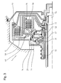
- the clutch assembly 1 in Figure 2 differs from the in Figure 1 clutch assembly 1 characterized in that not the first clutch 15, but the second clutch 16 can be actuated by means of a reversing lever 51.
- the actuating piston space 45 of the clutch 16 is formed of a disc 49 and the actuating piston 30 of the clutch 16.
- On the Actuation piston chamber 45 opposite side of the actuating piston 30 is a compensation chamber 47 is provided, which through the outer disk carrier 18 of the inner clutch 16 and the actuating piston 30 is formed.
- the actuating piston space 45 is via a pressure medium channel 52 with pressure medium provided.
Landscapes
- Engineering & Computer Science (AREA)
- General Engineering & Computer Science (AREA)
- Mechanical Engineering (AREA)
- Hydraulic Clutches, Magnetic Clutches, Fluid Clutches, And Fluid Joints (AREA)
Abstract
Description
- Figur 1
- in einer teilgeschnittenen Darstellung eine erfindungsgemäße Lamellen-Kupplungsanordnung mit einem der ersten Kupplung zugeordneten Umlenkhebel,
- Figur 2
- ein weiteres Ausführungsbeispiel der LamellenKupplungsanordnung mit einem der zweiten Kupplung zugeordneten Umlenkhebel,
- Figur 3
- ein weiteres Ausführungsbeispiel einer Kupplungsanordnung mit zwei Umlenkhebeln,
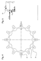
- Figur 4
- einen Ring mit einer Vielzahl von Umlenkhebeln und
- Figur 5
- eine Darstellung des Momenten- und Kräftegleichgewichtes an einem Umlenkhebel.
- FK
- Betätigungskraftkolben
- FAn
- Anpresskraft an die Lamellen
- MTF
- Tellerfederrückstellmoment
- FTF
- Tellerfederkraft bezüglich Krafteinleitungsdurchmesser
- L1
- Hebellänge des lamellenseitigen Arms des Umlenkhebels
- L2
- Hebellänge des betätigungskolbenseitigen Arms des Umlenkhebels
- 1
- Kupplungsanordnung
- 2
- Kurbelwelle
- 3
- Koppelende
- 4
- Getriebehohlwelle
- 5
- Getriebehohlwelle
- 6
- Vollwelle
- 7
- Getriebegehäuseglocke
- 8
- Deckel
- 9
- Sprengring
- 10
- Kupplungsnabe
- 11
- Ringdichtung
- 12
- Verzahnung
- 13
- äußere Mitnehmerscheibe
- 14
- Außenlamellenträger
- 15
- erste äußere Kupplung
- 16
- zweite innere Kupplung
- 17
- Zentralnabe
- 18
- Außenlamellenträger
- 19
- Nabe des Innenlamellenträgers
- 20
- Innenlamellenträger der äußeren Kupplung
- 21
- Verzahnung
- 22
- Nabe
- 23
- Innenlamellenträger der inneren Kupplung
- 24
- Verzahnung
- 25
- Außenlamellen der äußeren Kupplung
- 26
- Innenlamellen der äußeren Kupplung
- 27
- Außenlamellen der inneren Kupplung
- 28
- Innenlamellen der inneren Kupplung
- 29
- Betätigungskolben außen
- 30
- Betätigungskolben innen
- 31
- Betätigungskolbenraum
- 32
- Druckmedienkanal
- 33
- Ringdichtelement
- 34
- Ausgleichsraum
- 35
- Dichtung
- 36
- Druckmedienkanal
- 37
- Abflussfenster
- 38
- Fangblech
- 39
- Betätigungshebel
- 40
- geschlossener Ring
- 41
- Lasche
- 43
- Knie des Kniehebels
- 44
- Begrenzungsring
- 45
- Betätigungskolbenraum
- 46
- Druckmedienkanal
- 47
- Ausgleichsraum
- 48
- Spiralfeder
- 49
- Scheibe
- 50
- Umlenkhebel
- 51
- Umlenkhebel
- 52
- Druckmedienkanal
- 53
- Begrenzungsring
- 54
- Vollwelle
- 55
- Hohlwelle
- 56
- geschlossener Ring
- 57
- Tellerfeder
- 60
- Sicken
- p
- Berechnungspunkt
- FK
- Betätigungskraftkolben
- FAn
- Anpresskraft
- MTF
- Tellerfederrückstellmoment
- FTF
- Tellerfederkraft bezüglich Krafteinleitungsdurchmesser
- FHSG
- Reaktionskraft am Außenlamellenträger
- L1
- Hebellänge
- L2
- Hebellänge
Claims (19)
- Kupplungsanordnung mit mindestens einer ersten und mindestens einer zweiten Kupplung, wobei die erste Kupplung radial um die zweite Kupplung angeordnet ist, jede Kupplung bestehend aus einem Außenlamellenträger mit Außenlamellen, einem Innenlamellenträger mit Innenlamellen, einem Kolben der direkt oder indirekt bei Betätigung die Außen- gegen die Innenlamellen drückt, mindestens einem Rückstellelement, welches den Kolben bei Nichtbetätigung in seine Ausgangslage zurückführt, einem Betätigungskolbenraum zum Ausüben eines Betätigungsdruckes auf den Kolben,
dadurch gekennzeichnet, dass der Betätigungskolbenraum (31) der ersten Kupplung (15) gebildet ist aus dem Betätigungskolben (29) der ersten Kupplung (15) und dem Außenlamellenträger (18) der zweiten Kupplung (16) und/oder der Betätigungskolbenraum (45) der zweiten Kupplung (16) gebildet ist aus einer Scheibe (49) und dem Betätigungskolben (30) der zweiten Kupplung (16). - Kupplungsanordnung nach Anspruch 1,
dadurch gekennzeichnet, dass zumindest eine Kupplung (15, 16), vorzugsweise beide Kupplungen (15, 16), einen Ausgleichsraum (34, 47) aufweisen, über den der Änderung der Anpresskraft des Betätigungskolbens (29, 30) auf Grund der Drehbewegung der Kupplung (15, 16) entgegen gewirkt wird. - Kupplungsanordnung nach Anspruch 2,
dadurch gekennzeichnet, dass der Ausgleichsraum (34) der ersten Kupplung (15) gebildet ist aus dem Außenlamellenträger (14) der ersten Kupplung (15) und dem Betätigungskolben (29) der ersten Kupplung (15). - Kupplungsanordnung nach Anspruch 2 oder 3,
dadurch gekennzeichnet, dass der Ausgleichsraum (47) der zweiten Kupplung (16) gebildet ist aus dem Außenlamellenträger (18) der zweiten Kupplung (16) und dem Betätigungskolben (30) der zweiten Kupplung (16). - Kupplungsanordnung nach einem der vorhergehenden Ansprüche, dadurch gekennzeichnet, dass zur Kraftübertragung vom Betätigungskolben (29) der ersten Kupplung (15) auf die Lamellen (25, 26) der ersten Kupplung (15) mindestens ein äußerer Betätigungshebel (39) vorgesehen ist.
- Kupplungsanordnung nach einem der vorhergehenden Ansprüche, dadurch gekennzeichnet, dass zur Kraftübertragung vom Betätigungskolben (30) der zweiten Kupplung (16) auf die Lamellen (27, 28) der zweiten Kupplung (16) mindestens ein innerer Betätigungshebel (51) vorgesehen ist.
- Kupplungsanordnung nach Anspruch 5 oder 6,
dadurch gekennzeichnet, dass die äußeren und/oder die inneren Betätigungshebel als, vorzugsweise zweiarmiger, Umlenkhebel (50, 51) ausgebildet sind, wobei vorzugsweise die Richtung der von dem Umlenkhebel (50, 51) auf die Lamellen (25, 26, 27, 28) ausgeübten Kraft entgegengesetzt der Richtung der in den Umlenkhebel eingeleiteten Betätigungskraft des Betätigungskolbens (29, 30) gerichtet ist. - Kupplungsanordnung nach einem der Ansprüche 5 bis 7,
dadurch gekennzeichnet, dass die äu-βeren Betätigungshebel (39) über einen, vorzugsweise geschlossenen, äußeren Ring (40) miteinander verbunden sind. - Kupplungsanordnung nach einem der Ansprüche 5 bis 8,
dadurch gekennzeichnet, dass die inneren Betätigungshebel (51) über einen, vorzugsweise geschlossenen, inneren Ring (56) miteinander verbunden sind. - Kupplungsanordnung nach einem der Ansprüche 8 oder 9, da durch gekennzeichnet, dass die Betätigungshebel (50, 51), vorzugsweise gleichmäßig, über den Umfang der Ringe (40, 56) verteilt angeordnet sind.
- Kupplungsanordnung nach einem der Ansprüche 8 bis 10, da durch gekennzeichnet, dass die Rückstellelemente so angeordnet sind, dass die Rückstellkraft entgegen der Betätigungskraft des Betätigungskolbens (29, 30) auf die Betätigungshebel (50, 51) wirkt.
- Kupplungsanordnung nach Anspruch 11,
dadurch gekennzeichnet, dass die Rückstellelemente im äußeren und/oder inneren Ring integriert sind. - Kupplungsanordnung nach Anspruch 11 oder 12,
dadurch gekennzeichnet, dass als Rückstellelemente Rückstellfedern, vorzugsweise Tellerfedern, vorgesehen sind. - Kupplungsanordnung nach Anspruch 13,
dadurch gekennzeichnet, dass sich die Rückstellfedern des äußeren Rings (40) am Außenlamellenträger (14) der ersten Kupplung (15) abstützen. - Kupplungsanordnung nach einem der Ansprüche 8 bis 14, da durch gekennzeichnet, dass Mittel zur Zentrierung (41) des äußeren und/oder des inneren Rings vorgesehen sind.
- Kupplungsanordnung nach einem der Ansprüche 8 bis 15, da durch gekennzeichnet, dass Mittel zur Sicherung (41) des äußeren (40) und/oder inneren Rings (56) gegen Verdrehen vorgesehen sind.
- Kupplungsanordnung nach einem der Ansprüche 15 oder 16, d adurch gekennzeichnet, dass als Mittel zur Zentrierung (41) des äußeren Rings (40) und/oder als Mittel (41) zur Sicherung des äußeren Rings (40) gegen Verdrehen Laschen am Außenlamellenträger (14) vorgesehen sind, die zwischen die Umlenkhebel (50) des äußeren Rings (40) greifen.
- Kupplungsanordnung nach einem der Ansprüche 15 bis 17, d adurch gekennzeichnet, dass als Mittel zur Zentrierung des inneren Rings (56) und/oder als Mittel zur Sicherung des inneren Rings (56) gegen Verdrehen Laschen am Innenlamellenträger vorgesehen sind, die zwischen die Umlenkhebel (51) des inneren Rings (56) greifen.
- Kupplungsvorrichtung nach einem der Ansprüche 5 bis 18, d adurch gekennzeichnet, dass die Betätigungshebel (50, 51) zur Erhöhung der Steifigkeit Sicken aufweisen.
Priority Applications (2)
| Application Number | Priority Date | Filing Date | Title |
|---|---|---|---|
| EP04012868A EP1602846B1 (de) | 2004-06-01 | 2004-06-01 | Kupplungsanordnung |
| DE502004005499T DE502004005499D1 (de) | 2004-06-01 | 2004-06-01 | Kupplungsanordnung |
Applications Claiming Priority (1)
| Application Number | Priority Date | Filing Date | Title |
|---|---|---|---|
| EP04012868A EP1602846B1 (de) | 2004-06-01 | 2004-06-01 | Kupplungsanordnung |
Publications (2)
| Publication Number | Publication Date |
|---|---|
| EP1602846A1 true EP1602846A1 (de) | 2005-12-07 |
| EP1602846B1 EP1602846B1 (de) | 2007-11-14 |
Family
ID=34925199
Family Applications (1)
| Application Number | Title | Priority Date | Filing Date |
|---|---|---|---|
| EP04012868A Expired - Lifetime EP1602846B1 (de) | 2004-06-01 | 2004-06-01 | Kupplungsanordnung |
Country Status (2)
| Country | Link |
|---|---|
| EP (1) | EP1602846B1 (de) |
| DE (1) | DE502004005499D1 (de) |
Cited By (5)
| Publication number | Priority date | Publication date | Assignee | Title |
|---|---|---|---|---|
| WO2007113143A1 (de) * | 2006-03-30 | 2007-10-11 | Zf Friedrichshafen Ag | Vorrichtung zur betätigung einer lamellenkupplung in einem getriebe |
| DE102006027899A1 (de) * | 2006-06-17 | 2007-12-20 | Volkswagen Ag | Kupplungsanordnung in einem Getriebe eines Kraftfahrzeuges, vzw. einer Doppelkupplung in einem Kraftfahrzeuggetriebe |
| EP1972818A1 (de) * | 2007-03-21 | 2008-09-24 | Hoerbiger Antriebstechnik GmbH | Schaltkupplung |
| CN110273940A (zh) * | 2018-03-15 | 2019-09-24 | 法雷奥离合器公司 | 具有被构造用于促动盘包的内盘载体的双湿式离合器机构 |
| CN111442037A (zh) * | 2019-01-16 | 2020-07-24 | 舍弗勒技术股份两合公司 | 用于电车桥的湿式双离合器以及具有湿式双离合器的电车桥 |
Citations (2)
| Publication number | Priority date | Publication date | Assignee | Title |
|---|---|---|---|---|
| GB1121591A (en) * | 1966-01-05 | 1968-07-31 | Self Changing Gears Ltd | Improvements in or relating to a transmission arrangement |
| DE10143834A1 (de) * | 2001-09-07 | 2003-03-27 | Zf Sachs Ag | Kupplungssystem mit einer nasslaufenden oder/und hydraulisch betätigbaren Mehrfach-Kupplungseinrichtung |
-
2004
- 2004-06-01 DE DE502004005499T patent/DE502004005499D1/de not_active Expired - Lifetime
- 2004-06-01 EP EP04012868A patent/EP1602846B1/de not_active Expired - Lifetime
Patent Citations (2)
| Publication number | Priority date | Publication date | Assignee | Title |
|---|---|---|---|---|
| GB1121591A (en) * | 1966-01-05 | 1968-07-31 | Self Changing Gears Ltd | Improvements in or relating to a transmission arrangement |
| DE10143834A1 (de) * | 2001-09-07 | 2003-03-27 | Zf Sachs Ag | Kupplungssystem mit einer nasslaufenden oder/und hydraulisch betätigbaren Mehrfach-Kupplungseinrichtung |
Cited By (9)
| Publication number | Priority date | Publication date | Assignee | Title |
|---|---|---|---|---|
| WO2007113143A1 (de) * | 2006-03-30 | 2007-10-11 | Zf Friedrichshafen Ag | Vorrichtung zur betätigung einer lamellenkupplung in einem getriebe |
| CN101410647B (zh) * | 2006-03-30 | 2011-05-11 | Zf腓德烈斯哈芬股份公司 | 用于操作变速器中的多片式离合器的装置 |
| US7954615B2 (en) | 2006-03-30 | 2011-06-07 | Zf Friedrichshafen Ag | Device for actuating a multiplate clutch in a transmission |
| DE102006027899A1 (de) * | 2006-06-17 | 2007-12-20 | Volkswagen Ag | Kupplungsanordnung in einem Getriebe eines Kraftfahrzeuges, vzw. einer Doppelkupplung in einem Kraftfahrzeuggetriebe |
| DE102006027899B4 (de) * | 2006-06-17 | 2016-06-23 | Volkswagen Ag | Kupplungsanordnung in einem Getriebe eines Kraftfahrzeuges |
| EP1972818A1 (de) * | 2007-03-21 | 2008-09-24 | Hoerbiger Antriebstechnik GmbH | Schaltkupplung |
| CN110273940A (zh) * | 2018-03-15 | 2019-09-24 | 法雷奥离合器公司 | 具有被构造用于促动盘包的内盘载体的双湿式离合器机构 |
| CN110273940B (zh) * | 2018-03-15 | 2022-09-13 | 法雷奥离合器公司 | 具有被构造用于促动盘包的内盘载体的双湿式离合器机构 |
| CN111442037A (zh) * | 2019-01-16 | 2020-07-24 | 舍弗勒技术股份两合公司 | 用于电车桥的湿式双离合器以及具有湿式双离合器的电车桥 |
Also Published As
| Publication number | Publication date |
|---|---|
| DE502004005499D1 (de) | 2007-12-27 |
| EP1602846B1 (de) | 2007-11-14 |
Similar Documents
| Publication | Publication Date | Title |
|---|---|---|
| DE10034677B4 (de) | Mehrfachkupplungsanordnung | |
| DE10223780C1 (de) | Gangschaltgetriebe für ein Kraftfahrzeug mit hydraulisch betätigbarer Mehrfachkupplung | |
| DE102009006647B4 (de) | Doppelkupplungsanordnung | |
| DE10146606A1 (de) | Mehrfach-Kupplungseinrichtung mit axial nebeneinander angeordneten Lamellen-Kupplungsanordnungen | |
| DE102009039223A1 (de) | Doppelkupplungsanordnung für ein Getriebe mit zwei Eingangswellen | |
| DE19830951A1 (de) | Lamellenkupplung in einem leistungsverzweigten Getriebe | |
| EP1715216B1 (de) | Torsionsschwingungsdämpfer | |
| DE102012201524A1 (de) | Drehmomentübertragungseinrichtung | |
| EP1914434A2 (de) | Drehmomentübertragungseinrichtung | |
| DE10133693A1 (de) | Torsionsschwingungsdämpfer | |
| DE10114281B4 (de) | Mehrfach-Kupplungseinrichtung und Radiallagerungskonzept hierfür | |
| DE19536952A1 (de) | Hydrodynamischer Drehmomentwandler mit Überbrückungskupplung | |
| EP1780435A2 (de) | Doppelkupplungseinrichtung in radialer Bauart | |
| DE102011003846A1 (de) | Drehmomentübertragungsanordnung, insbesondere hydrodynamischer Drehmomentwandler | |
| EP1602846B1 (de) | Kupplungsanordnung | |
| DE102005039272A1 (de) | Kopplungsvorrichtung | |
| WO2002044589A1 (de) | Hydrodynamischer drehmomentwandler | |
| WO2009021582A1 (de) | Kupplungseinrichtung mit verbessertem fliehölausgleich | |
| DE102006044218A1 (de) | Kupplungssystem mit besonderem Ausgleichsraum | |
| DE102008057657A1 (de) | Kraftübertragungsvorrichtung | |
| DE102005044227A1 (de) | Lamellen-Kupplungseinrichtung | |
| DE19816518B4 (de) | Torsionsschwingungsdämpfer mit einer strömungsbildenden Einrichtung | |
| DE102014207260A1 (de) | Torsionsschwingungsdämpfer mit einer Dämpfungseinrichtung, einem Tilgersystem und einer Masseeinrichtung | |
| DE102013205611A1 (de) | Lamellenkupplungsanordnung | |
| EP2706251B1 (de) | Reibkupplung |
Legal Events
| Date | Code | Title | Description |
|---|---|---|---|
| PUAI | Public reference made under article 153(3) epc to a published international application that has entered the european phase |
Free format text: ORIGINAL CODE: 0009012 |
|
| AK | Designated contracting states |
Kind code of ref document: A1 Designated state(s): AT BE BG CH CY CZ DE DK EE ES FI FR GB GR HU IE IT LI LU MC NL PL PT RO SE SI SK TR |
|
| AX | Request for extension of the european patent |
Extension state: AL HR LT LV MK |
|
| 17P | Request for examination filed |
Effective date: 20060216 |
|
| AKX | Designation fees paid |
Designated state(s): DE FR GB IT |
|
| 17Q | First examination report despatched |
Effective date: 20060412 |
|
| GRAP | Despatch of communication of intention to grant a patent |
Free format text: ORIGINAL CODE: EPIDOSNIGR1 |
|
| GRAS | Grant fee paid |
Free format text: ORIGINAL CODE: EPIDOSNIGR3 |
|
| GRAA | (expected) grant |
Free format text: ORIGINAL CODE: 0009210 |
|
| AK | Designated contracting states |
Kind code of ref document: B1 Designated state(s): DE FR GB IT |
|
| REG | Reference to a national code |
Ref country code: GB Ref legal event code: FG4D Free format text: NOT ENGLISH |
|
| GBT | Gb: translation of ep patent filed (gb section 77(6)(a)/1977) |
Effective date: 20071128 |
|
| REF | Corresponds to: |
Ref document number: 502004005499 Country of ref document: DE Date of ref document: 20071227 Kind code of ref document: P |
|
| ET | Fr: translation filed | ||
| PLBE | No opposition filed within time limit |
Free format text: ORIGINAL CODE: 0009261 |
|
| STAA | Information on the status of an ep patent application or granted ep patent |
Free format text: STATUS: NO OPPOSITION FILED WITHIN TIME LIMIT |
|
| 26N | No opposition filed |
Effective date: 20080815 |
|
| PGFP | Annual fee paid to national office [announced via postgrant information from national office to epo] |
Ref country code: IT Payment date: 20090622 Year of fee payment: 6 |
|
| PGFP | Annual fee paid to national office [announced via postgrant information from national office to epo] |
Ref country code: GB Payment date: 20090507 Year of fee payment: 6 |
|
| GBPC | Gb: european patent ceased through non-payment of renewal fee |
Effective date: 20100601 |
|
| PG25 | Lapsed in a contracting state [announced via postgrant information from national office to epo] |
Ref country code: IT Free format text: LAPSE BECAUSE OF NON-PAYMENT OF DUE FEES Effective date: 20100601 |
|
| PG25 | Lapsed in a contracting state [announced via postgrant information from national office to epo] |
Ref country code: GB Free format text: LAPSE BECAUSE OF NON-PAYMENT OF DUE FEES Effective date: 20100601 |
|
| REG | Reference to a national code |
Ref country code: FR Ref legal event code: PLFP Year of fee payment: 13 |
|
| REG | Reference to a national code |
Ref country code: FR Ref legal event code: PLFP Year of fee payment: 14 |
|
| REG | Reference to a national code |
Ref country code: FR Ref legal event code: PLFP Year of fee payment: 15 |
|
| PGFP | Annual fee paid to national office [announced via postgrant information from national office to epo] |
Ref country code: DE Payment date: 20210512 Year of fee payment: 18 Ref country code: FR Payment date: 20210520 Year of fee payment: 18 |
|
| REG | Reference to a national code |
Ref country code: DE Ref legal event code: R119 Ref document number: 502004005499 Country of ref document: DE |
|
| PG25 | Lapsed in a contracting state [announced via postgrant information from national office to epo] |
Ref country code: FR Free format text: LAPSE BECAUSE OF NON-PAYMENT OF DUE FEES Effective date: 20220630 |
|
| PG25 | Lapsed in a contracting state [announced via postgrant information from national office to epo] |
Ref country code: DE Free format text: LAPSE BECAUSE OF NON-PAYMENT OF DUE FEES Effective date: 20230103 |