EP1602458A1 - Roboterhandachse mit einer Schlauchführung für einen Lackierroboter - Google Patents
Roboterhandachse mit einer Schlauchführung für einen Lackierroboter Download PDFInfo
- Publication number
- EP1602458A1 EP1602458A1 EP05010954A EP05010954A EP1602458A1 EP 1602458 A1 EP1602458 A1 EP 1602458A1 EP 05010954 A EP05010954 A EP 05010954A EP 05010954 A EP05010954 A EP 05010954A EP 1602458 A1 EP1602458 A1 EP 1602458A1
- Authority
- EP
- European Patent Office
- Prior art keywords
- guide
- hose
- robot hand
- robot
- discs
- Prior art date
- Legal status (The legal status is an assumption and is not a legal conclusion. Google has not performed a legal analysis and makes no representation as to the accuracy of the status listed.)
- Granted
Links
Images


Classifications
-
- B—PERFORMING OPERATIONS; TRANSPORTING
- B25—HAND TOOLS; PORTABLE POWER-DRIVEN TOOLS; MANIPULATORS
- B25J—MANIPULATORS; CHAMBERS PROVIDED WITH MANIPULATION DEVICES
- B25J19/00—Accessories fitted to manipulators, e.g. for monitoring, for viewing; Safety devices combined with or specially adapted for use in connection with manipulators
- B25J19/0025—Means for supplying energy to the end effector
- B25J19/0029—Means for supplying energy to the end effector arranged within the different robot elements
Definitions
- the invention relates to a robot hand axis according to the preamble of claim 1.
- the robot hand axis fixed, usually smooth polished metal tubes that are straight or curved can and pick up the hoses.
- the transitions between the individual metal tubes should be as straight as possible or with the smallest possible angle changes, with small Radii or even sharp-edged transitions are avoided to the mechanical loads of the hoses in case of a change to keep the position of the robot's hand axis low.
- the hoses are in one Flexible protective hose installed in the robot hand axis laid.
- the advantage of this variant is the more continuous Course of the hose passage, as the radii of curvature usually larger.
- the protective tube is attached to the output flange of the robot hand axis and turns with the hose package with.
- This protective tube will preferably at the end of its two sides with the same direction Rotary motion driven to a larger mechanical Torsional load to avoid.
- the synchronous rotation of the protective tube with the hoses inside it prevented advantageous that the hoses on the inner wall of the Grind protective hose. Instead, those in the Protective hose guided hoses only the relative movements withstand, due to the axial movements at a change in position of the robot hand axis arise.
- a disadvantage of the two known described above Variants of a hose guide in a robot hand axis is the fact that the hoses when kinking or turning the Robot hand axis change their position in the hose guide. There is a risk that by axial stretching and upsetting the hoses in the hose guide loops that are trapped in the remaining hose package, kink and wear out very quickly. In addition, you can the hoses tense in different positions and then slide against each other under high pressure.
- DE 102 16 081 A1 and DE 195 09 116 A1 are hose guide elements known that an orderly leadership of hoses or other lines.
- the hose guide element is used for guidance of pipes or hoses outside the robot's hand axis, while DE 195 09 116 A1 only the structural design the hose guide element describes without affecting the To enter arrangement in a robot hand axis.
- a conventional robot hand axis is also known from DE 101 39 088 A1 known.
- the invention is therefore based on the object, the Hose guide in a robot hand axis corresponding to improve.
- the invention comprises the general technical teaching in which Robot hand axis to arrange a special hose guide element which leads the tubes in a lateral direction and thereby prevents the above-mentioned looping.
- the hose guide element therefore preferably has at least an axially extending guide bore for receiving of the hose to be guided, wherein the guide bore in axial direction preferably completely through the hose guide element goes through it.
- the hose guide element several axially successively arranged guide discs with a given outer diameter in which in each case at least one guide bore for the leading Hose is arranged, with the guide holes arranged axially aligned in the individual guide discs are.
- This offers the advantage that the hoses are inside the hose guide not only laterally guided at one point but preferably over the entire length of Hose guide.
- the division of the Hose guide element in a plurality of axially arranged one behind the other Guide discs advantageous a high bending flexibility the hose guide element, which is particularly in a robot's hand axis is important.
- the individual guide discs of the hose guide element can be mechanically connected to one another axial Displacement of the individual guide discs in the assembled state to avoid.
- connection of the individual guide discs with each other is preferably carried out by a centrally arranged elastic Switzerlandseele.
- the central arrangement of the mechanical connection the guide discs advantageously allows a large Biegenachgiebtechnik especially in a highly flexible robot hand axis important is.
- the train soul preferably also in the axial direction elastic to corresponding Strokes when changing the position of the robot's hand axis give in to give.
- the leadership takes place the hoses by a spirally encircling guide bar, arranged in the axially continuous guide bore is.
- the individual guide discs or between the adjacent spiral turns of the spiral Guide web preferably each with a groove arranged a predetermined groove width, wherein the groove width preferably between 5% and 30% of the outer diameter of the Hose guide element amounts.
- the guide bore in the Hose guide element preferably an excess having leading to the hose, so that the leading Hose in the guide bore can slide axially. Thereby is a clamping of the hose leading to in the invention Hose guide element prevents such a Jamming to unwanted mechanical stresses could lead.
- the hose guide element not only a single Guide bore on, but a variety of guide holes, the over the cross section of the hose guide element are arranged distributed.
- the individual guide bores can be different Have cross-sections, with the larger guide holes for thick and inflexible hoses preferably are arranged inside, while the smaller guide holes for the thin and thus flexible hoses preferably are arranged outside. This is advantageous because of the mechanical Strain in the so-called neutral fiber in the Middle is lower.
- the hose guide element preferably a predetermined bending elasticity and / or a predetermined Tensile elasticity, so that the hose guide element adjust accordingly if the robot position changes can.
- the guide washers, the spiral guide bar, the mounting flanges and / or the Switzerlandseele preferably exist made of polyurethane (PU). It is particularly advantageous here, if the tension core is made of a softer material as the guide washers, the spiral guide bar and / or the mounting flanges.
- PU polyurethane
- the Switzerlandseele can be formed here as a separate component be that with the guide washers, the spiral guide bar and / or glued to the mounting flanges.
- the hose guide element on the contact surfaces to the surrounding protective tube with a lubricant such as petroleum jelly be coated to the friction and thus reduce wear.
- the protective tube facing the inside located hose guide element preferably an excess on, whereby the friction and thus the wear further reduced becomes.
- the invention also includes a complete painting robot with such a hand axis.
- FIG. 1 shows a largely conventional structured robot hand axis 1 of a painting robot, wherein the robot hand axis 1 on a robot arm 2 of the painting robot is attached and at its distal end a mounting flange 3, on which, for example, a rotary atomizer can be attached.
- the robot hand axis 1 extend a plurality of hoses, wherein For simplicity, only a single tube 4 shown is.
- the current through the robot hand axis 1 through Hoses carry, for example, coating agents or drive air to drive the rotary atomizer turbine too.
- the hose 4 extends in this case in a hose passage 5 within the robot's hand axis 1, wherein the guide of the hose 4 within the hose passage 5 through a hose guide member 6 can be made, as in the Figures 2-5 and 6 and 7 is shown and described below becomes.
- the hose guide element 6 has numerous circular disk-shaped, axially spaced and axially one behind the other arranged guide discs 7, in which over the Cross-section distributed a plurality of guide holes 8 arranged are in which in the mounted state of the tube 4 and the not shown further tubes run.
- each guide discs 7 is located respectively a groove 9 to at a bending of the robot hand axis. 1 to prevent the individual guide discs 7 at their Collide peripheral edge and thereby the range of motion restrict the robot hand axis 1.
- the individual guide discs are tapered 7 in the radial direction to the outside.
- the hose guide element 6 each have a mounting flange 10, 11, wherein the two mounting flanges 10, 11 against rotation are connected to a protective tube 12, which is the hose guide element 6 surrounds.
- the individual guide discs 7, the mounting flanges 10, 11 and the Werner 13 here are made of polyurethane (PU), wherein the Werner 13 made of a softer material exists as the guide discs 7 and the mounting flanges 10, 11.
- PU polyurethane
- a lubricant such as Vaseline is to the wear-promoting friction between the Guide discs 7 and the inner wall of the protective tube 12th to reduce.
- the protective tube 12 also has an excess opposite to the guide discs 7, which is also the friction and thus reduces the wear.
- the guide holes 8 in the individual guide discs 7 have over the hoses leading to an excess on to a jamming of leading hoses in the To prevent guide washers 7, as this disturbing mechanical could cause tension.
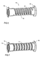
- Figures 6 and 7 show a further embodiment a hose guide according to the invention with a hose guide element 15, which is arranged in a protective tube 16 is.
- the hose guide element 15 in this case has a spiral shape circumferential guide bar 17, wherein in the individual Spiral gears of the guide web 17 each axially aligned Guide bores are arranged, each having a hose take up and lead in a lateral direction.
- the hose guide element 15 is also made here Polyurethane (PU), being between the adjacent spiral Guide webs 17 a groove remains free, which is a Biegenachgiebtechnik the hose guide member 15 allows.
- PU Polyurethane
Landscapes
- Engineering & Computer Science (AREA)
- Robotics (AREA)
- Mechanical Engineering (AREA)
- Manipulator (AREA)
- Spray Control Apparatus (AREA)
- Details Or Accessories Of Spraying Plant Or Apparatus (AREA)
- Toys (AREA)
- Coating Apparatus (AREA)
Abstract
Description
- Figur 1
- eine Seitenansicht einer Roboterhandachse eines Lackierroboters ohne das erfindungsgemäße Schlauchführungselement,
- Figur 2
- eine Perspektivansicht eines Teils des erfindungsgemäßen Schlauchführungselements,
- Figuren 3A und 3B
- Perspektivansichten eines Teils des erfindungsgemäßen Schlauchführungselements,
- Figur 4
- eine weitere Perspektivansicht des erfindungsgemäßen Schlauchführungselements,
- Figur 5
- das in Figur 4 gezeigte Schlauchführungselement im eingebauten Zustand in einem Schutzschlauch,
- Figur 6
- eine Querschnittsansicht eines alternativen Ausführungsbeispiels einer Schlauchführung mit einem Schutzschlauch und einem darin angeordneten Schlauchführungselement mit einem spiralförmig umlaufenden Führungssteg sowie
- Figur 7
- eine Perspektivansicht des Schlauchführungselements aus Figur 6.
- 1
- Roboterhandachse
- 2
- Roboterarm
- 3
- Befestigungsflansch
- 4
- Schlauch
- 5
- Schlauchdurchführung
- 6
- Schlauchführungselement
- 7
- Führungsscheiben
- 8
- Führungsbohrungen
- 9
- Nut
- 10
- Befestigungsflansch
- 11
- Befestigungsflansch
- 12
- Schutzschlauch
- 13
- Zugseele
- 14
- Schlauchführung
- 15
- Schlauchführungselement
- 16
- Schutzschlauch
- 17
- Führungssteg
- 18
- Befestigungsflansch
- 19
- Befestigungsflansch
Claims (15)
- Roboterhandachse (1) mitgekennzeichnet durcha) einer Schlauchdurchführung (5) undb) einer in der Schlauchdurchführung (5) angeordneten Schlauchführung (14) mit einem Schutzschlauch (12, 16),c) ein in dem Schutzschlauch (12, 16) angeordnetes Schlauchführungselement (6, 15),d) wobei das Schlauchführungselement (6, 15) zur Führung mindestens eines Schlauchs (4) in der Schlauchdurchführung (5) in der Roboterhandachse mindestens eine axial verlaufende Führungsbohrung (8) zur Aufnahme des zu führenden Schlauchs (4) aufweist,e) während an den gegenüber liegenden Enden des Schlauchführungselements (6, 15) zwei Befestigungsflansche (10, 11, 18, 19) verdrehsicher angebracht sind,f) wobei die Befestigungsflansche (10, 11, 18, 19) verdrehsicher mit dem Schutzschlauch (12, 16) verbunden sind,g) so dass sich das Schlauchführungselement (6, 15) mit dem darin geführten Schlauchpaket bei einer Drehung der Roboterhandachse (1) mitdreht.
- Roboterhandachse (1) nach Anspruch 1, gekennzeichnet durch mehrere axial hintereinander angeordnete Führungsscheiben (7) mit einem vorgegebenen Außendurchmesser, in denen jeweils mindestens eine Führungsbohrung (8) für den Schlauch (4) angeordnet ist, wobei die Führungsbohrungen (8) in den einzelnen Führungsscheiben (7) axial fluchtend angeordnet sind.
- Roboterhandachse (1) nach Anspruch 2, dadurch gekennzeichnet, dass sämtliche Führungsscheiben (7) mechanisch miteinander verbunden sind.
- Roboterhandachse (1) nach Anspruch 2, dadurch gekennzeichnet, dass die axial außen liegenden Führungsscheiben (7) mechanisch miteinander verbunden sind, während die axial innen liegenden Führungsscheiben (7) mechanisch voneinander getrennt sind.
- Roboterhandachse (1) nach Anspruch 3 oder 4, dadurch gekennzeichnet, dass zur mechanischen Verbindung der Führungsscheiben (7) untereinander eine mittig angeordnete elastische Zugseele (13) vorgesehen ist.
- Roboterhandachse (1) nach Anspruch 2, dadurch gekennzeichnet, dass sämtliche Führungsscheiben (7) mechanisch voneinander getrennt sind.
- Roboterhandachse (1) nach Anspruch 1, gekennzeichnet durch einen spiralförmig umlaufenden Führungssteg (17), in dem die Führungsbohrung (8) angeordnet ist, wobei die Führungsbohrung (8) axial durchgeht.
- Roboterhandachse (1) nach einem der Ansprüche 2 bis 7, dadurch gekennzeichnet, dass sich die einzelnen Führungsscheiben (7) oder die einzelnen Spiralgänge des spiralförmigen Führungsstegs (17) in Radialrichtung nach außen verjüngen.
- Roboterhandachse (1) nach einem der Ansprüche 2 bis 8, dadurch gekennzeichnet, dass die einzelnen Führungsscheiben (7) oder die einzelnen Spiralgänge des spiralförmigen Führungsstegs (17) jeweils durch eine Nut (9) mit einer vorgegebenen Nutbreite voneinander getrennt sind.
- Roboterhandachse (1) nach einem der vorhergehenden Ansprüche, dadurch gekennzeichnet, dass die Führungsbohrung (8) einen vorgegebenen Innenquerschnitt aufweist, während der zu führende Schlauch (4) einen vorgegebenen Außenquerschnitt aufweist, wobei der Innenquerschnitt der Führungsbohrung (8) mit einem vorgegebenen Übermaß an den Außenquerschnitt des Schlauchs (4) angepasst ist.
- Roboterhandachse (1) nach einem der Ansprüche 2 bis 10, dadurch gekennzeichnet, dass in den Führungsscheiben (7) oder in dem spiralförmigen Führungssteg (17) mehrere Führungsbohrungen (8) über den Querschnitt verteilt angeordnet sind.
- Roboterhandachse (1) nach Anspruch 11, dadurch gekennzeichnet, dass die einzelnen Führungsbohrungen (8) unterschiedliche Querschnitte aufweisen, wobei die größeren Führungsbohrungen (8) für die dicken Schläuche innen angeordnet sind, während die kleineren Führungsbohrungen (8) für die dünnen Schläuche außen angeordnet sind.
- Roboterhandachse (1) nach einem der vorhergehenden Ansprüche, gekennzeichnet durch eine Biegeelastizität und/oder eine Zugelastizität zur Formanpassung des Schlauchführungselements (6, 15) an eine Formänderung der Schlauchdurchführung (5) aufgrund einer Änderung der Roboterstellung.
- Roboterhandachse (1) nach einem der vorhergehenden Ansprüche, dadurch gekennzeichnet, dass der Schutzschlauch (12, 16) gegenüber dem Schlauchführungselement (6, 15) ein Übermaß aufweist.
- Lackierroboter mit einer Roboterhandachse (1) nach einem der vorhergehenden Ansprüche.
Applications Claiming Priority (2)
| Application Number | Priority Date | Filing Date | Title |
|---|---|---|---|
| DE102004026573 | 2004-06-01 | ||
| DE102004026573A DE102004026573A1 (de) | 2004-06-01 | 2004-06-01 | Schlauchführungselement für einen Lackierroboter |
Publications (2)
| Publication Number | Publication Date |
|---|---|
| EP1602458A1 true EP1602458A1 (de) | 2005-12-07 |
| EP1602458B1 EP1602458B1 (de) | 2007-08-15 |
Family
ID=34936744
Family Applications (1)
| Application Number | Title | Priority Date | Filing Date |
|---|---|---|---|
| EP05010954A Expired - Lifetime EP1602458B1 (de) | 2004-06-01 | 2005-05-20 | Roboterhandachse mit einer Schlauchführung für einen Lackierroboter |
Country Status (4)
| Country | Link |
|---|---|
| EP (1) | EP1602458B1 (de) |
| AT (1) | ATE369944T1 (de) |
| DE (2) | DE102004026573A1 (de) |
| ES (1) | ES2290818T3 (de) |
Cited By (1)
| Publication number | Priority date | Publication date | Assignee | Title |
|---|---|---|---|---|
| DE102007051018A1 (de) | 2007-10-25 | 2009-04-30 | Daimler Ag | Fertigungseinrichtung |
Families Citing this family (5)
| Publication number | Priority date | Publication date | Assignee | Title |
|---|---|---|---|---|
| JP5568121B2 (ja) | 2012-11-12 | 2014-08-06 | ファナック株式会社 | 産業用ロボットの手首先端部における線条体案内装置および産業用ロボット |
| JP5698783B2 (ja) * | 2013-03-29 | 2015-04-08 | ファナック株式会社 | 分線盤を備えたロボット |
| DE102016003966A1 (de) * | 2016-04-01 | 2017-10-05 | Dürr Systems Ag | Beschichtungsroboter |
| DE102016008112A1 (de) * | 2016-06-28 | 2017-12-28 | Eisele Pneumatics Gmbh & Co. Kg | Handhabungssystem |
| DE102018133412A1 (de) * | 2018-12-21 | 2020-06-25 | Eisenmann Se | Kanalstruktur für einen Applikationsroboter und Applikationsroboter |
Citations (3)
| Publication number | Priority date | Publication date | Assignee | Title |
|---|---|---|---|---|
| EP0756918A1 (de) * | 1995-02-21 | 1997-02-05 | Kabushiki Kaisha Kobe Seiko Sho | Handgelenk für industrieroboter |
| EP0873826A2 (de) * | 1997-04-23 | 1998-10-28 | COMAU S.p.A. | Robotergelenk |
| DE10216081A1 (de) * | 2002-04-11 | 2003-10-30 | Kabelschlepp Gmbh | Roboter mit einer Leitungsführungseinrichtung |
Family Cites Families (4)
| Publication number | Priority date | Publication date | Assignee | Title |
|---|---|---|---|---|
| DE3715118A1 (de) * | 1987-05-06 | 1988-11-17 | Gore W L & Co Gmbh | Versorgungsleitungsanordnung fuer einen roboter |
| DE19509116C2 (de) * | 1995-03-16 | 2000-01-05 | Deutsch Zentr Luft & Raumfahrt | Flexible Struktur |
| DE10139088A1 (de) * | 2001-08-16 | 2003-02-27 | Duerr Systems Gmbh | Manipulatormaschine mit einer zu dem Arbeitsgerät geführten Leitungsanordnung |
| DE20114231U1 (de) * | 2001-08-29 | 2001-11-29 | LEONI Protec Cable Systems GmbH, 98574 Schmalkalden | Industrieroboter |
-
2004
- 2004-06-01 DE DE102004026573A patent/DE102004026573A1/de not_active Ceased
-
2005
- 2005-05-20 DE DE502005001212T patent/DE502005001212D1/de not_active Expired - Lifetime
- 2005-05-20 EP EP05010954A patent/EP1602458B1/de not_active Expired - Lifetime
- 2005-05-20 AT AT05010954T patent/ATE369944T1/de not_active IP Right Cessation
- 2005-05-20 ES ES05010954T patent/ES2290818T3/es not_active Expired - Lifetime
Patent Citations (3)
| Publication number | Priority date | Publication date | Assignee | Title |
|---|---|---|---|---|
| EP0756918A1 (de) * | 1995-02-21 | 1997-02-05 | Kabushiki Kaisha Kobe Seiko Sho | Handgelenk für industrieroboter |
| EP0873826A2 (de) * | 1997-04-23 | 1998-10-28 | COMAU S.p.A. | Robotergelenk |
| DE10216081A1 (de) * | 2002-04-11 | 2003-10-30 | Kabelschlepp Gmbh | Roboter mit einer Leitungsführungseinrichtung |
Cited By (1)
| Publication number | Priority date | Publication date | Assignee | Title |
|---|---|---|---|---|
| DE102007051018A1 (de) | 2007-10-25 | 2009-04-30 | Daimler Ag | Fertigungseinrichtung |
Also Published As
| Publication number | Publication date |
|---|---|
| DE102004026573A1 (de) | 2005-12-29 |
| ES2290818T3 (es) | 2008-02-16 |
| EP1602458B1 (de) | 2007-08-15 |
| ATE369944T1 (de) | 2007-09-15 |
| DE502005001212D1 (de) | 2007-09-27 |
Similar Documents
| Publication | Publication Date | Title |
|---|---|---|
| DE3209596C2 (de) | Gleichlaufdrehgelenk | |
| DE3309551C2 (de) | Tripodegelenk | |
| EP0552429B1 (de) | Endoskop mit einem steuerbaren distalen Endstück | |
| DE3431033C3 (de) | Roboterhandgelenk | |
| EP1200753B1 (de) | Energiezuführungskette | |
| DE69017784T2 (de) | Drahtseil mit durchgehendem Lumen. | |
| DE69207634T2 (de) | Einstellvorrichtung für einen Bowdenzug die frei drehend auf der Führungshülle montiert ist | |
| DE69500857T2 (de) | Luft- und Flüssigkeits-Schlauchsystem für eine Handspritzpistole | |
| DE19907412C2 (de) | Kupplung für Stahlwendelschläuche | |
| EP2877100A1 (de) | Schaft für medizinisches instrument mit beweglichen abschnitten | |
| DE102008007552A1 (de) | Vorrichtung zur Erhöhung der Biegesteifigkeit von Schläuchen | |
| EP1447183B1 (de) | Roboter, deren Leitung durch einen axial nachgiebigen Balg geführt ist | |
| DE3215210A1 (de) | Zahnaerztliches handstueck | |
| EP1573231B1 (de) | Kugelgewindetrieb | |
| DE102013103155A1 (de) | Gleichlaufgelenk in Form eines Gegenbahngelenks | |
| EP1888960A1 (de) | Verankerungselement für rohrkupplungen | |
| DE102008043474B4 (de) | Kugelumlaufspindelmodul | |
| EP1602458B1 (de) | Roboterhandachse mit einer Schlauchführung für einen Lackierroboter | |
| DE102008043476A1 (de) | Kugelumlaufspindelmodul | |
| DE102017001943A1 (de) | Anschlusssystem | |
| DE3334104A1 (de) | Gelenkbeweglich biegbarer roboterarm | |
| WO1998023883A1 (de) | Planetengetriebe, insbesondere zum einsatz in bohrlöchern | |
| DE3013182A1 (de) | Homokinetisches gleitgelenk in tripod-bauart und getriebe mit schwimmend gelagerter welle zum einbau desselben | |
| EP1579964A1 (de) | Roboter mit Leitungsanordnung innerhalb eines Schwenkgelenks | |
| CH702888A2 (de) | Rotationswerkzeug für eine Vorrichtung insbesondere zum Reinigen von Rohrleitungen. |
Legal Events
| Date | Code | Title | Description |
|---|---|---|---|
| PUAI | Public reference made under article 153(3) epc to a published international application that has entered the european phase |
Free format text: ORIGINAL CODE: 0009012 |
|
| 17P | Request for examination filed |
Effective date: 20050907 |
|
| AK | Designated contracting states |
Kind code of ref document: A1 Designated state(s): AT BE BG CH CY CZ DE DK EE ES FI FR GB GR HU IE IS IT LI LT LU MC NL PL PT RO SE SI SK TR |
|
| AX | Request for extension of the european patent |
Extension state: AL BA HR LV MK YU |
|
| AKX | Designation fees paid |
Designated state(s): AT BE BG CH CY CZ DE DK EE ES FI FR GB GR HU IE IS IT LI LT LU MC NL PL PT RO SE SI SK TR |
|
| GRAP | Despatch of communication of intention to grant a patent |
Free format text: ORIGINAL CODE: EPIDOSNIGR1 |
|
| GRAS | Grant fee paid |
Free format text: ORIGINAL CODE: EPIDOSNIGR3 |
|
| GRAA | (expected) grant |
Free format text: ORIGINAL CODE: 0009210 |
|
| AK | Designated contracting states |
Kind code of ref document: B1 Designated state(s): AT BE BG CH CY CZ DE DK EE ES FI FR GB GR HU IE IS IT LI LT LU MC NL PL PT RO SE SI SK TR |
|
| REG | Reference to a national code |
Ref country code: GB Ref legal event code: FG4D Free format text: NOT ENGLISH |
|
| REG | Reference to a national code |
Ref country code: CH Ref legal event code: EP |
|
| REG | Reference to a national code |
Ref country code: IE Ref legal event code: FG4D Free format text: LANGUAGE OF EP DOCUMENT: GERMAN |
|
| GBT | Gb: translation of ep patent filed (gb section 77(6)(a)/1977) |
Effective date: 20070831 |
|
| REF | Corresponds to: |
Ref document number: 502005001212 Country of ref document: DE Date of ref document: 20070927 Kind code of ref document: P |
|
| REG | Reference to a national code |
Ref country code: DE Ref legal event code: R096 Ref document number: 502005001212 Country of ref document: DE Effective date: 20070927 |
|
| REG | Reference to a national code |
Ref country code: SE Ref legal event code: TRGR |
|
| ET | Fr: translation filed | ||
| PG25 | Lapsed in a contracting state [announced via postgrant information from national office to epo] |
Ref country code: LT Free format text: LAPSE BECAUSE OF FAILURE TO SUBMIT A TRANSLATION OF THE DESCRIPTION OR TO PAY THE FEE WITHIN THE PRESCRIBED TIME-LIMIT Effective date: 20070815 Ref country code: IS Free format text: LAPSE BECAUSE OF FAILURE TO SUBMIT A TRANSLATION OF THE DESCRIPTION OR TO PAY THE FEE WITHIN THE PRESCRIBED TIME-LIMIT Effective date: 20071215 Ref country code: FI Free format text: LAPSE BECAUSE OF FAILURE TO SUBMIT A TRANSLATION OF THE DESCRIPTION OR TO PAY THE FEE WITHIN THE PRESCRIBED TIME-LIMIT Effective date: 20070815 Ref country code: BG Free format text: LAPSE BECAUSE OF FAILURE TO SUBMIT A TRANSLATION OF THE DESCRIPTION OR TO PAY THE FEE WITHIN THE PRESCRIBED TIME-LIMIT Effective date: 20071115 |
|
| REG | Reference to a national code |
Ref country code: ES Ref legal event code: FG2A Ref document number: 2290818 Country of ref document: ES Kind code of ref document: T3 |
|
| PG25 | Lapsed in a contracting state [announced via postgrant information from national office to epo] |
Ref country code: PL Free format text: LAPSE BECAUSE OF FAILURE TO SUBMIT A TRANSLATION OF THE DESCRIPTION OR TO PAY THE FEE WITHIN THE PRESCRIBED TIME-LIMIT Effective date: 20070815 |
|
| REG | Reference to a national code |
Ref country code: IE Ref legal event code: FD4D |
|
| PG25 | Lapsed in a contracting state [announced via postgrant information from national office to epo] |
Ref country code: GR Free format text: LAPSE BECAUSE OF FAILURE TO SUBMIT A TRANSLATION OF THE DESCRIPTION OR TO PAY THE FEE WITHIN THE PRESCRIBED TIME-LIMIT Effective date: 20071116 Ref country code: DK Free format text: LAPSE BECAUSE OF FAILURE TO SUBMIT A TRANSLATION OF THE DESCRIPTION OR TO PAY THE FEE WITHIN THE PRESCRIBED TIME-LIMIT Effective date: 20070815 |
|
| PG25 | Lapsed in a contracting state [announced via postgrant information from national office to epo] |
Ref country code: CZ Free format text: LAPSE BECAUSE OF FAILURE TO SUBMIT A TRANSLATION OF THE DESCRIPTION OR TO PAY THE FEE WITHIN THE PRESCRIBED TIME-LIMIT Effective date: 20070815 Ref country code: SK Free format text: LAPSE BECAUSE OF FAILURE TO SUBMIT A TRANSLATION OF THE DESCRIPTION OR TO PAY THE FEE WITHIN THE PRESCRIBED TIME-LIMIT Effective date: 20070815 Ref country code: PT Free format text: LAPSE BECAUSE OF FAILURE TO SUBMIT A TRANSLATION OF THE DESCRIPTION OR TO PAY THE FEE WITHIN THE PRESCRIBED TIME-LIMIT Effective date: 20080115 Ref country code: IE Free format text: LAPSE BECAUSE OF FAILURE TO SUBMIT A TRANSLATION OF THE DESCRIPTION OR TO PAY THE FEE WITHIN THE PRESCRIBED TIME-LIMIT Effective date: 20070815 |
|
| PLBE | No opposition filed within time limit |
Free format text: ORIGINAL CODE: 0009261 |
|
| STAA | Information on the status of an ep patent application or granted ep patent |
Free format text: STATUS: NO OPPOSITION FILED WITHIN TIME LIMIT |
|
| PG25 | Lapsed in a contracting state [announced via postgrant information from national office to epo] |
Ref country code: RO Free format text: LAPSE BECAUSE OF FAILURE TO SUBMIT A TRANSLATION OF THE DESCRIPTION OR TO PAY THE FEE WITHIN THE PRESCRIBED TIME-LIMIT Effective date: 20070815 |
|
| 26N | No opposition filed |
Effective date: 20080516 |
|
| REG | Reference to a national code |
Ref country code: DE Ref legal event code: R097 Ref document number: 502005001212 Country of ref document: DE Effective date: 20080516 |
|
| PG25 | Lapsed in a contracting state [announced via postgrant information from national office to epo] |
Ref country code: MC Free format text: LAPSE BECAUSE OF NON-PAYMENT OF DUE FEES Effective date: 20080531 |
|
| PG25 | Lapsed in a contracting state [announced via postgrant information from national office to epo] |
Ref country code: EE Free format text: LAPSE BECAUSE OF FAILURE TO SUBMIT A TRANSLATION OF THE DESCRIPTION OR TO PAY THE FEE WITHIN THE PRESCRIBED TIME-LIMIT Effective date: 20070815 |
|
| PG25 | Lapsed in a contracting state [announced via postgrant information from national office to epo] |
Ref country code: SI Free format text: LAPSE BECAUSE OF FAILURE TO SUBMIT A TRANSLATION OF THE DESCRIPTION OR TO PAY THE FEE WITHIN THE PRESCRIBED TIME-LIMIT Effective date: 20070815 |
|
| PG25 | Lapsed in a contracting state [announced via postgrant information from national office to epo] |
Ref country code: CY Free format text: LAPSE BECAUSE OF FAILURE TO SUBMIT A TRANSLATION OF THE DESCRIPTION OR TO PAY THE FEE WITHIN THE PRESCRIBED TIME-LIMIT Effective date: 20070815 |
|
| PG25 | Lapsed in a contracting state [announced via postgrant information from national office to epo] |
Ref country code: AT Free format text: LAPSE BECAUSE OF NON-PAYMENT OF DUE FEES Effective date: 20080520 |
|
| REG | Reference to a national code |
Ref country code: CH Ref legal event code: PL |
|
| PG25 | Lapsed in a contracting state [announced via postgrant information from national office to epo] |
Ref country code: LI Free format text: LAPSE BECAUSE OF NON-PAYMENT OF DUE FEES Effective date: 20090531 Ref country code: CH Free format text: LAPSE BECAUSE OF NON-PAYMENT OF DUE FEES Effective date: 20090531 |
|
| REG | Reference to a national code |
Ref country code: DE Ref legal event code: R081 Ref document number: 502005001212 Country of ref document: DE Owner name: DUERR SYSTEMS AG, DE Free format text: FORMER OWNER: DUERR SYSTEMS GMBH, 70435 STUTTGART, DE Effective date: 20100115 |
|
| PG25 | Lapsed in a contracting state [announced via postgrant information from national office to epo] |
Ref country code: LU Free format text: LAPSE BECAUSE OF NON-PAYMENT OF DUE FEES Effective date: 20080520 Ref country code: HU Free format text: LAPSE BECAUSE OF FAILURE TO SUBMIT A TRANSLATION OF THE DESCRIPTION OR TO PAY THE FEE WITHIN THE PRESCRIBED TIME-LIMIT Effective date: 20080216 |
|
| PG25 | Lapsed in a contracting state [announced via postgrant information from national office to epo] |
Ref country code: TR Free format text: LAPSE BECAUSE OF FAILURE TO SUBMIT A TRANSLATION OF THE DESCRIPTION OR TO PAY THE FEE WITHIN THE PRESCRIBED TIME-LIMIT Effective date: 20070815 |
|
| REG | Reference to a national code |
Ref country code: FR Ref legal event code: PLFP Year of fee payment: 12 |
|
| REG | Reference to a national code |
Ref country code: DE Ref legal event code: R082 Ref document number: 502005001212 Country of ref document: DE Representative=s name: V. BEZOLD & PARTNER PATENTANWAELTE - PARTG MBB, DE Ref country code: DE Ref legal event code: R081 Ref document number: 502005001212 Country of ref document: DE Owner name: DUERR SYSTEMS AG, DE Free format text: FORMER OWNER: DUERR SYSTEMS GMBH, 74321 BIETIGHEIM-BISSINGEN, DE |
|
| REG | Reference to a national code |
Ref country code: DE Ref legal event code: R082 Ref document number: 502005001212 Country of ref document: DE Representative=s name: V. BEZOLD & PARTNER PATENTANWAELTE - PARTG MBB, DE Ref country code: DE Ref legal event code: R081 Ref document number: 502005001212 Country of ref document: DE Owner name: DUERR SYSTEMS AG, DE Free format text: FORMER OWNER: DUERR SYSTEMS AG, 74321 BIETIGHEIM-BISSINGEN, DE |
|
| REG | Reference to a national code |
Ref country code: FR Ref legal event code: PLFP Year of fee payment: 13 |
|
| REG | Reference to a national code |
Ref country code: FR Ref legal event code: PLFP Year of fee payment: 14 |
|
| P01 | Opt-out of the competence of the unified patent court (upc) registered |
Effective date: 20230512 |
|
| PGFP | Annual fee paid to national office [announced via postgrant information from national office to epo] |
Ref country code: NL Payment date: 20240521 Year of fee payment: 20 |
|
| PGFP | Annual fee paid to national office [announced via postgrant information from national office to epo] |
Ref country code: GB Payment date: 20240521 Year of fee payment: 20 |
|
| PGFP | Annual fee paid to national office [announced via postgrant information from national office to epo] |
Ref country code: DE Payment date: 20240521 Year of fee payment: 20 |
|
| PGFP | Annual fee paid to national office [announced via postgrant information from national office to epo] |
Ref country code: ES Payment date: 20240626 Year of fee payment: 20 |
|
| PGFP | Annual fee paid to national office [announced via postgrant information from national office to epo] |
Ref country code: FR Payment date: 20240529 Year of fee payment: 20 |
|
| PGFP | Annual fee paid to national office [announced via postgrant information from national office to epo] |
Ref country code: SE Payment date: 20240521 Year of fee payment: 20 Ref country code: BE Payment date: 20240521 Year of fee payment: 20 |
|
| PGFP | Annual fee paid to national office [announced via postgrant information from national office to epo] |
Ref country code: IT Payment date: 20240524 Year of fee payment: 20 |
|
| REG | Reference to a national code |
Ref country code: DE Ref legal event code: R071 Ref document number: 502005001212 Country of ref document: DE |
|
| REG | Reference to a national code |
Ref country code: NL Ref legal event code: MK Effective date: 20250519 |
|
| REG | Reference to a national code |
Ref country code: ES Ref legal event code: FD2A Effective date: 20250527 |
|
| REG | Reference to a national code |
Ref country code: GB Ref legal event code: PE20 Expiry date: 20250519 |
|
| REG | Reference to a national code |
Ref country code: SE Ref legal event code: EUG |
|
| PG25 | Lapsed in a contracting state [announced via postgrant information from national office to epo] |
Ref country code: ES Free format text: LAPSE BECAUSE OF EXPIRATION OF PROTECTION Effective date: 20250521 Ref country code: GB Free format text: LAPSE BECAUSE OF EXPIRATION OF PROTECTION Effective date: 20250519 |
|
| REG | Reference to a national code |
Ref country code: BE Ref legal event code: MK Effective date: 20250520 |