EP1601539B1 - Pneumatique a flanc renforce et procede de fabrication - Google Patents
Pneumatique a flanc renforce et procede de fabrication Download PDFInfo
- Publication number
- EP1601539B1 EP1601539B1 EP04714757A EP04714757A EP1601539B1 EP 1601539 B1 EP1601539 B1 EP 1601539B1 EP 04714757 A EP04714757 A EP 04714757A EP 04714757 A EP04714757 A EP 04714757A EP 1601539 B1 EP1601539 B1 EP 1601539B1
- Authority
- EP
- European Patent Office
- Prior art keywords
- annular
- reinforcement
- tyre
- sidewall
- diameter
- Prior art date
- Legal status (The legal status is an assumption and is not a legal conclusion. Google has not performed a legal analysis and makes no representation as to the accuracy of the status listed.)
- Expired - Lifetime
Links
- 238000004519 manufacturing process Methods 0.000 title description 10
- 238000000034 method Methods 0.000 title description 9
- 230000002787 reinforcement Effects 0.000 claims abstract description 119
- 239000011324 bead Substances 0.000 claims abstract description 61
- 229920001971 elastomer Polymers 0.000 claims description 17
- 230000006835 compression Effects 0.000 claims 1
- 238000007906 compression Methods 0.000 claims 1
- 230000003014 reinforcing effect Effects 0.000 description 30
- 239000000203 mixture Substances 0.000 description 11
- 238000005096 rolling process Methods 0.000 description 5
- RRHGJUQNOFWUDK-UHFFFAOYSA-N Isoprene Chemical compound CC(=C)C=C RRHGJUQNOFWUDK-UHFFFAOYSA-N 0.000 description 4
- 238000004873 anchoring Methods 0.000 description 4
- 150000001875 compounds Chemical class 0.000 description 4
- 230000008878 coupling Effects 0.000 description 4
- 238000010168 coupling process Methods 0.000 description 4
- 238000005859 coupling reaction Methods 0.000 description 4
- 239000002184 metal Substances 0.000 description 4
- 229920001195 polyisoprene Polymers 0.000 description 4
- 238000010276 construction Methods 0.000 description 3
- 241001417494 Sciaenidae Species 0.000 description 2
- 230000015572 biosynthetic process Effects 0.000 description 2
- 238000000465 moulding Methods 0.000 description 2
- 230000008569 process Effects 0.000 description 2
- 239000004753 textile Substances 0.000 description 2
- 238000004073 vulcanization Methods 0.000 description 2
- 238000004804 winding Methods 0.000 description 2
- 241001415961 Gaviidae Species 0.000 description 1
- 241000897276 Termes Species 0.000 description 1
- 235000009508 confectionery Nutrition 0.000 description 1
- 238000009826 distribution Methods 0.000 description 1
- 230000006872 improvement Effects 0.000 description 1
- 239000007769 metal material Substances 0.000 description 1
- 230000004048 modification Effects 0.000 description 1
- 238000012986 modification Methods 0.000 description 1
- 235000012830 plain croissants Nutrition 0.000 description 1
- 239000004033 plastic Substances 0.000 description 1
- 238000011084 recovery Methods 0.000 description 1
- 238000010074 rubber mixing Methods 0.000 description 1
- 238000007493 shaping process Methods 0.000 description 1
Images

Classifications
-
- B—PERFORMING OPERATIONS; TRANSPORTING
- B60—VEHICLES IN GENERAL
- B60C—VEHICLE TYRES; TYRE INFLATION; TYRE CHANGING; CONNECTING VALVES TO INFLATABLE ELASTIC BODIES IN GENERAL; DEVICES OR ARRANGEMENTS RELATED TO TYRES
- B60C15/00—Tyre beads, e.g. ply turn-up or overlap
- B60C15/0009—Tyre beads, e.g. ply turn-up or overlap features of the carcass terminal portion
- B60C15/0081—Tyre beads, e.g. ply turn-up or overlap features of the carcass terminal portion the carcass plies folded around or between more than one bead core
-
- B—PERFORMING OPERATIONS; TRANSPORTING
- B29—WORKING OF PLASTICS; WORKING OF SUBSTANCES IN A PLASTIC STATE IN GENERAL
- B29D—PRODUCING PARTICULAR ARTICLES FROM PLASTICS OR FROM SUBSTANCES IN A PLASTIC STATE
- B29D30/00—Producing pneumatic or solid tyres or parts thereof
- B29D30/06—Pneumatic tyres or parts thereof (e.g. produced by casting, moulding, compression moulding, injection moulding, centrifugal casting)
- B29D30/08—Building tyres
-
- B—PERFORMING OPERATIONS; TRANSPORTING
- B60—VEHICLES IN GENERAL
- B60C—VEHICLE TYRES; TYRE INFLATION; TYRE CHANGING; CONNECTING VALVES TO INFLATABLE ELASTIC BODIES IN GENERAL; DEVICES OR ARRANGEMENTS RELATED TO TYRES
- B60C13/00—Tyre sidewalls; Protecting, decorating, marking, or the like, thereof
- B60C13/009—Tyre sidewalls; Protecting, decorating, marking, or the like, thereof comprising additional bead cores in the sidewall
-
- B—PERFORMING OPERATIONS; TRANSPORTING
- B60—VEHICLES IN GENERAL
- B60C—VEHICLE TYRES; TYRE INFLATION; TYRE CHANGING; CONNECTING VALVES TO INFLATABLE ELASTIC BODIES IN GENERAL; DEVICES OR ARRANGEMENTS RELATED TO TYRES
- B60C15/00—Tyre beads, e.g. ply turn-up or overlap
- B60C15/0009—Tyre beads, e.g. ply turn-up or overlap features of the carcass terminal portion
- B60C15/0018—Tyre beads, e.g. ply turn-up or overlap features of the carcass terminal portion not folded around the bead core, e.g. floating or down ply
-
- B—PERFORMING OPERATIONS; TRANSPORTING
- B60—VEHICLES IN GENERAL
- B60C—VEHICLE TYRES; TYRE INFLATION; TYRE CHANGING; CONNECTING VALVES TO INFLATABLE ELASTIC BODIES IN GENERAL; DEVICES OR ARRANGEMENTS RELATED TO TYRES
- B60C15/00—Tyre beads, e.g. ply turn-up or overlap
- B60C15/06—Flipper strips, fillers, or chafing strips and reinforcing layers for the construction of the bead
-
- B—PERFORMING OPERATIONS; TRANSPORTING
- B60—VEHICLES IN GENERAL
- B60C—VEHICLE TYRES; TYRE INFLATION; TYRE CHANGING; CONNECTING VALVES TO INFLATABLE ELASTIC BODIES IN GENERAL; DEVICES OR ARRANGEMENTS RELATED TO TYRES
- B60C3/00—Tyres characterised by the transverse section
- B60C3/04—Tyres characterised by the transverse section characterised by the relative dimensions of the section, e.g. low profile
-
- B—PERFORMING OPERATIONS; TRANSPORTING
- B60—VEHICLES IN GENERAL
- B60C—VEHICLE TYRES; TYRE INFLATION; TYRE CHANGING; CONNECTING VALVES TO INFLATABLE ELASTIC BODIES IN GENERAL; DEVICES OR ARRANGEMENTS RELATED TO TYRES
- B60C9/00—Reinforcements or ply arrangement of pneumatic tyres
- B60C9/02—Carcasses
- B60C9/14—Carcasses built-up with sheets, webs, or films of homogeneous material, e.g. synthetics, sheet metal, rubber
-
- B—PERFORMING OPERATIONS; TRANSPORTING
- B29—WORKING OF PLASTICS; WORKING OF SUBSTANCES IN A PLASTIC STATE IN GENERAL
- B29D—PRODUCING PARTICULAR ARTICLES FROM PLASTICS OR FROM SUBSTANCES IN A PLASTIC STATE
- B29D30/00—Producing pneumatic or solid tyres or parts thereof
- B29D30/06—Pneumatic tyres or parts thereof (e.g. produced by casting, moulding, compression moulding, injection moulding, centrifugal casting)
- B29D30/72—Side-walls
- B29D2030/722—Reinforcing the sidewalls, e.g. by using filaments, fibers or additional reinforcing layers
-
- Y—GENERAL TAGGING OF NEW TECHNOLOGICAL DEVELOPMENTS; GENERAL TAGGING OF CROSS-SECTIONAL TECHNOLOGIES SPANNING OVER SEVERAL SECTIONS OF THE IPC; TECHNICAL SUBJECTS COVERED BY FORMER USPC CROSS-REFERENCE ART COLLECTIONS [XRACs] AND DIGESTS
- Y10—TECHNICAL SUBJECTS COVERED BY FORMER USPC
- Y10T—TECHNICAL SUBJECTS COVERED BY FORMER US CLASSIFICATION
- Y10T152/00—Resilient tires and wheels
- Y10T152/10—Tires, resilient
- Y10T152/10495—Pneumatic tire or inner tube
- Y10T152/10765—Characterized by belt or breaker structure
-
- Y—GENERAL TAGGING OF NEW TECHNOLOGICAL DEVELOPMENTS; GENERAL TAGGING OF CROSS-SECTIONAL TECHNOLOGIES SPANNING OVER SEVERAL SECTIONS OF THE IPC; TECHNICAL SUBJECTS COVERED BY FORMER USPC CROSS-REFERENCE ART COLLECTIONS [XRACs] AND DIGESTS
- Y10—TECHNICAL SUBJECTS COVERED BY FORMER USPC
- Y10T—TECHNICAL SUBJECTS COVERED BY FORMER US CLASSIFICATION
- Y10T152/00—Resilient tires and wheels
- Y10T152/10—Tires, resilient
- Y10T152/10495—Pneumatic tire or inner tube
- Y10T152/10819—Characterized by the structure of the bead portion of the tire
- Y10T152/10837—Bead characterized by the radial extent of apex, flipper or chafer into tire sidewall
-
- Y—GENERAL TAGGING OF NEW TECHNOLOGICAL DEVELOPMENTS; GENERAL TAGGING OF CROSS-SECTIONAL TECHNOLOGIES SPANNING OVER SEVERAL SECTIONS OF THE IPC; TECHNICAL SUBJECTS COVERED BY FORMER USPC CROSS-REFERENCE ART COLLECTIONS [XRACs] AND DIGESTS
- Y10—TECHNICAL SUBJECTS COVERED BY FORMER USPC
- Y10T—TECHNICAL SUBJECTS COVERED BY FORMER US CLASSIFICATION
- Y10T152/00—Resilient tires and wheels
- Y10T152/10—Tires, resilient
- Y10T152/10495—Pneumatic tire or inner tube
- Y10T152/10855—Characterized by the carcass, carcass material, or physical arrangement of the carcass materials
- Y10T152/10864—Sidewall stiffening or reinforcing means other than main carcass plies or foldups thereof about beads
Definitions
- the present invention relates to tires and more particularly to the reinforcing structure of the tire sidewalls.
- a tire comprises a carcass reinforcement formed of a plurality of reinforcements (cables, wires in particular) embedded in a rubber mixture, said reinforcements being oriented in preferential directions.
- reinforcements of the carcass reinforcement in the form of one or more plies, can be arranged to make an angle close to or equal to 90 ° with the circumferential direction on the tire; other known possibilities are to have these reinforcements on several carcass plies, the reinforcements of each ply being substantially parallel to each other and making an angle different from 90 ° with the circumferential direction while being crossed with the reinforcements of each ply adjacent carcass.
- Reinforcements of the carcass reinforcement may be distributed in the tire without forming webs (or layers) being for example placed individually or by a strip of several reinforcements parallel to each other in said strip.
- the carcass reinforcement extends in the crown of the tire and in each flank to anchor on the annular reinforcing structure of each bead.
- One possibility is to anchor the carcass reinforcement formed of a carcass ply by partial winding around said annular structure.
- carcass reinforcement comprising several carcass plies, at least one said plies being anchored by partial winding around an annular reinforcing structure forming a reversal and at least one carcass ply being anchored in the same bead by mechanical coupling on said upturn, then passing radially inside the the annular reinforcement structure.
- the latter architecture is of interest for these tires in that it gives greater rigidity to the tire sidewalls and substantially increases the performance in high speed cornering.
- Another family of solutions consists in combining with a carcass reinforcement the presence of additional reinforcements of crossed elements in at least one of the flanks.
- Patent FR 1 590 025 substantially repeats the same principle by improving it by providing a suitable carcass reinforcement profile in the tire sidewall.
- the carcass reinforcement portion adjacent to the tread extends beyond mid-flank height away from the median plane and having a relatively low curvature meridian profile, while the second portion radially interposed between the first portion and the carcass reinforcement anchoring rod has a reduced radial height and a relatively highly curved meridian profile, the two portions described being joined by a second circumferential reinforcement in the form of a bead wire.
- the same principle of an additional rod placed at the junction of the sidewall and the bead is taken up by the patent DE 2 357 265.
- maximum diameter Dc of the mounting rim means the diameter of the circle on which are the points of the rim radially furthest from the axis of rotation.
- the diameter Dc of the rim corresponds to the diameter of the circle passing through the points radially outside said flanges.
- internal diameter of an additional annular structure is meant the diameter of the circle passing through the points of said radially innermost structure.
- the difference between the inner diameter of the additional radially innermost reinforcing reinforcing structure of each sidewall and the diameter Dj of the rim seat on the same side as the sidewall containing said annular structure is at least equal to 20% of the diameter. Dj .
- the difference between the internal diameter of the additional annular structure of each radially outermost flank and the diameter Dj of the rim seat on the same side as the flank containing said annular structure is at most equal to 1.6 times the height. of section H of the tire measured on the same side.
- the additional annular structures adjacent to the same sidewall, taken in pairs, are separated by a rubber profile whose height, measured in the radial direction, is at least 15 mm in order to optimize the behavior of the tire in the face of significant lateral forces.
- the carcass reinforcement may be anchored either wholly or only partially to any of the annular bead or flank reinforcement structures.
- Each additional annular reinforcement structure is provided to take back part of the total carcass tension when the tire is mounted on its rim and inflated to its operating pressure.
- a circumferential tension of at least 10% of the tension of the bead reinforcement structure is preferable.
- two additional structures of the same diameter may also be used in the same sidewall, these structures being axially offset, at least a portion of the carcass reinforcement being anchored on at least one of said additional structures.
- the sum of the circumferential forces taken up by the annular flank structures is at least equal to the circumferential force to which the bead reinforcement structure is subjected.
- each carcass reinforcement portion anchored on each annular flank and bead reinforcement structure forms a reversal, each inversion of a carcass reinforcement portion being mechanically coupled to at least one other portion of reinforcement anchored to an annular reinforcement structure of larger diameter.
- each annular reinforcing structure a rubber compound filling profile having a shore hardness A at least equal to 50, this section ensuring a mechanical coupling between the carcass reinforcement portion anchored on said structure and the reversal of said portion.
- These profiles may also be of a different nature and / or mechanical characteristic depending on the position in the same sidewall.
- annular reinforcing structures and rubber mix profiles having a Shore A hardness of at least 50 substantially increases the resistance to transverse stresses.
- the upturn formed by said portion is located axially outside of at least the annular reinforcing structure radially to the nearest outside.
- each portion of the carcass reinforcement is anchored by shear coupling to at least one annular reinforcing structure formed of inextensible reinforcements arranged in at least one stack in the radial direction on the tire.
- each annular reinforcing structure is constituted by at least two substantially circumferential reinforcing stacks, the carcass reinforcement portion anchored on each annular structure being placed axially between two of said stacks.
- the various portions of carcass reinforcement may be arranged symmetrically or non-symmetrically with respect to the median plane of the tire while being concentric with each other.
- the shaping operation can be performed in one or more successive steps.
- the different carcass reinforcement portions are formed on different front drum to assemble them concentrically to each other and then to conform them to the shape of a torus.
- Another possibility is after each formation of a carcass reinforcement portion to slightly conform it before forming another reinforcing portion on the toric surface obtained and so on.
- the turns of each carcass reinforcement portion around the annular reinforcement structures may be placed either radially inwardly of said annular structures or radially outwardly of said structures.
- the described method applies to the formation of a tire in which the carcass reinforcement is anchored, in addition to the beads, to at least one other additional structure of diameter larger than the diameter of the bead reinforcement structure.
- This method allows an excellent positioning of the various annular reinforcing structures relative to each other in the radial direction thus ensuring, by a very good centering, a very good uniformity of rolling.
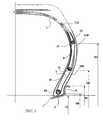
- FIG. 1 shows a partial view of a cross-section of a tire 1 according to the invention, this symmetrical tire and comprising two additional structures 21, 22 for reinforcing the flanks 2 around which are anchored by turning the portions of a reinforcement 3.
- This tire 1 is mounted on its mounting rim J comprising a rim seat S extended axially and radially outwards by a rim flange R whose radially outermost points are on a circle of diameter Dc.
- the tire 1 has a height H of section measured, in the plane of section, between the nominal diameter of the rim Dj (taken substantially at the intersection of the rim R. and the rim seat S) and the point M radially the outermost of the tread.
- This tire has a section width S measured between the points of the axially furthest flanks.
- the tire has a shape ratio equal to 0.70.
- the tire 1 shown schematically comprises a portion forming the crown 4 of the tire, this portion reinforced by a crown reinforcement 41 being provided radially on the outside with a tread 5 intended to come into contact with the roadway during taxiing. .
- a crown reinforcement 41 being provided radially on the outside with a tread 5 intended to come into contact with the roadway during taxiing.
- Extending this vertex 4 is the flank 2 which ends at its radially inner end by a bead 6 intended to come into contact with the mounting rim J of the tire.
- said tire comprises a so-called carcass reinforcement 3 extending from the top to the beads through the sidewalls.
- a first portion 30 of the carcass reinforcement is anchored around an annular bead reinforcement structure 60 (in the form of a metal rod) by passing axially from the inside of the tire outwards to form a 300.
- the internal diameter D 0 of this bead wire 60 is smaller than the outside diameter of the rim flange R (corresponding in this case to the maximum diameter Dc of the rim) so as to hold the bead in place on the rim. mounting.
- a second portion 31 of the same carcass reinforcement extends throughout the entire vertex and partially in the sidewall until it is wound around an additional annular reinforcing structure 21 by passing axially from the inside of the tire towards the inside.
- the outer annular structure 21 is here a metal rod of smaller cross-section than that of the bead wire 60 and of internal diameter D1. This diameter is greater than the outside diameter Dc of the rim flange R; the difference between the internal diameter D1 and the diameter Dj of the seat of the rim is greater than 20% of the diameter Dj.
- a third and last portion 32 of the same carcass reinforcement extends throughout the vertex and partially in the sidewall until it is wrapped around a second additional annular reinforcement structure 22 passing axially from the inside of the pneumatically outwardly to form a turnaround 320.
- the second annular structure additional 22 is here a metal rod identical to the first additional annular structure 21 and internal diameter D2 which in the present case is such that the difference (D2-D1) is substantially equal to the difference (D1-D0).
- the difference between the internal diameter D2 and the diameter Dj of the seat of the rim is equal to 1.2 times the section height H of the tire.
- each first and second carcass reinforcement portion are respectively engaged between the first and second additional annular structures 21 and 22 so as to ensure good mechanical coupling of said reinforcement portions.
- the additional annular flank structures are positioned on either side of the point F of the sidewall of greater width on the section shown.
- One of the important points of this construction is to be able to distribute the forces in the carcass reinforcement between the different annular reinforcement structures so that the circumferential tension forces in each additional flank structure is at least equal to 10% of the circumferential force supported by the bead rod inflation at the pressure of use.
- the sum of the forces taken up by all the additional reinforcement structures of a flank 21, 22 is at least equal to the circumferential force supported by the bead wire 60.
- turns 310 and 320 of the first and second portions 31 and 32 of the carcass reinforcement 3 (respectively anchored on the bead wire and the flank rod radially closest to the rim) follow the axially outer faces of said sections 7 and 8 before partially overlapping the rollover portion of the carcass reinforcement portion radially closest (respectively 310 and 320).
- the flange rods 21 and 22 used in the variants of FIGS. 1 and 2 can easily be replaced by any annular structure having a circumferential extension module such that the force recovery of each of said flange rods is at least 10 mm. % of the circumferential force exerted on the bead wire.
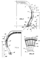
- At least one of the annular structures may be replaced by a structure formed of a series of circumferentially wound wires or cables to form substantially radially oriented cells as shown in the variants of FIGS. 3 and 4.
- each of the annular bead reinforcement structures 60 'and flank 21' and 22 ' is formed of at least two stacks of wire ropes.
- a first structure 60 'in the bead consists of four stacks 600' enclosing a first carcass reinforcement portion 30 '3', this first structure being located radially below the diameter Dc of the rim flange when the tire is mounted on said rim.
- the internal diameter of this first structure is denoted D0 ' .
- the internal diameters of the annular reinforcing structures 21 ', 22', 23 ', denoted respectively D1', D2 ', D3' and the diameter D0 ' of the bead structure 60' are such that the distances between these structures on the section of Figure 3 are substantially equal.
- the stacks of the additional annular structures 21 ', 22', 23 'for reinforcing the flanks are placed axially on either side of all the portions 30', 31 ', 32', 33 ' carcass reinforcement.
- the annular structure 23 ', of diameter D3 ', radially outermost is formed of two stacks between which pass the four carcass reinforcement portions.
- tire architectures are applicable to tires of all categories and in particular for passenger vehicles and particularly high speed vehicles but also tires for heavy goods vehicles, for two wheels, for civil engineering machines, plane.
- tires can be manufactured with processes involving core fabrication.
- some of the reinforcements 111 of the same ply 11 forming a carcass reinforcement may be anchored on a first annular structure 40 and other reinforcements 112, 113 of the same ply 11 may the being respectively on two other annular structures 41 and 42 (the view of Figure 10 corresponds to a partial view of a sidewall).
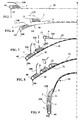
- FIGS. 5 to 9 show a succession of manufacturing steps of a tire blank comprising a carcass reinforcement 3 anchored to a bead wire 6 in each bead and to two rods 21, 22 in each of the sidewalls of the tire.
- This manufacture substantially corresponds to the tire according to the invention described with the support of FIG.
- a first carcass portion 30 is placed on a drum (only half of said portion is represented here without explicitly showing said drum), then a first rubber compound section 7 is wound on this first portion near each lateral end of said portion and then a bead wire 60 of diameter D0 is threaded concentrically to the drum to come into lateral contact with said first section 7.
- the end portion of this carcass portion is partially returned around the rod 60 while reserving a portion of the turnaround 300 to be plated in a next step on a second carcass portion.
- this first carcass reinforcement portion 30 is assembled with a second portion 31 made on another drum (or on the same drum after conformation to the desired diameter) in the same manner as said first portion.
- This second portion 31 of carcass comprises a portion of the carcass reinforcement partially wound around a rod 21 of internal diameter D1, itself in lateral contact with a second rubber compound profile 8.
- the assembly is made by conforming slightly the first portion of carcass 30 concentrically to the second portion 31 and axially bringing closer the bead rods 60 (towards the median plane marked XX in Figures 5 to 9).
- the next step (FIG. 7) is identical to the previous step in that a third carcass portion 32 is constituted. This third portion 32 wraps around a rod 22 of internal diameter D2 and a third section 9 of rubber mixture.
- the bead and flange rods are brought axially towards the median plane of the tire blank while conforming this blank, for example by internal inflation, according to known means.
- a tire blank 10 is obtained (FIG. 9) in the form of a torus, the turns 300 and 310 of the first and second carcass reinforcement portions being pressed against the rubber sections 7, 8 and 9. .
- the manufacture of the tire is continued, by application, in a manner known per se, of the plies of a reinforcing belt and then of a tread before placing this blank inside a molding mold and vulcanizing rubber mixtures.
Landscapes
- Engineering & Computer Science (AREA)
- Mechanical Engineering (AREA)
- Tyre Moulding (AREA)
- Tires In General (AREA)
- Manufacture Of Alloys Or Alloy Compounds (AREA)
- Processing And Handling Of Plastics And Other Materials For Molding In General (AREA)
- Yarns And Mechanical Finishing Of Yarns Or Ropes (AREA)
Applications Claiming Priority (3)
| Application Number | Priority Date | Filing Date | Title |
|---|---|---|---|
| FR0302574 | 2003-03-03 | ||
| FR0302574 | 2003-03-03 | ||
| PCT/EP2004/001910 WO2004078494A1 (fr) | 2003-03-03 | 2004-02-26 | Pneumatique a flanc renforce et procede de fabrication |
Publications (2)
| Publication Number | Publication Date |
|---|---|
| EP1601539A1 EP1601539A1 (fr) | 2005-12-07 |
| EP1601539B1 true EP1601539B1 (fr) | 2006-12-27 |
Family
ID=32947093
Family Applications (1)
| Application Number | Title | Priority Date | Filing Date |
|---|---|---|---|
| EP04714757A Expired - Lifetime EP1601539B1 (fr) | 2003-03-03 | 2004-02-26 | Pneumatique a flanc renforce et procede de fabrication |
Country Status (8)
| Country | Link |
|---|---|
| US (1) | US7278458B2 (enExample) |
| EP (1) | EP1601539B1 (enExample) |
| JP (1) | JP4536715B2 (enExample) |
| CN (1) | CN100391752C (enExample) |
| AT (1) | ATE349344T1 (enExample) |
| BR (1) | BRPI0407933A (enExample) |
| DE (1) | DE602004003917T2 (enExample) |
| WO (1) | WO2004078494A1 (enExample) |
Families Citing this family (7)
| Publication number | Priority date | Publication date | Assignee | Title |
|---|---|---|---|---|
| JP4521220B2 (ja) * | 2004-05-17 | 2010-08-11 | 株式会社ブリヂストン | 空気入りタイヤ |
| US20100024960A1 (en) * | 2005-09-01 | 2010-02-04 | Bridgestone Americas Tire Operations, Llc | Body ply and insert assembly method |
| US20070044889A1 (en) * | 2005-09-01 | 2007-03-01 | Bridgestone Firestone North American Tire, Llc | Tire having a sidewall reinforcement |
| FR2911299B1 (fr) * | 2007-01-17 | 2009-03-06 | Michelin Soc Tech | Armature additionnelle de flanc de pneumatique poids lourd |
| EP2318201B1 (en) * | 2008-06-27 | 2019-05-22 | Compagnie Générale des Etablissements Michelin | Patch having reinforcements with staggered ends |
| US9227467B2 (en) * | 2013-07-22 | 2016-01-05 | E I Du Pont De Nemours And Company | Pneumatic tire |
| WO2019035281A1 (ja) * | 2017-08-18 | 2019-02-21 | 横浜ゴム株式会社 | 空気入りタイヤ |
Family Cites Families (18)
| Publication number | Priority date | Publication date | Assignee | Title |
|---|---|---|---|---|
| US1548370A (en) * | 1921-08-12 | 1925-08-04 | Fisk Rubber Co | Tire |
| US2186178A (en) * | 1937-02-11 | 1940-01-09 | Jacob George Smith | Pneumatic tire |
| NL137766C (enExample) * | 1968-10-25 | |||
| DE2357265A1 (de) * | 1973-11-16 | 1975-05-28 | Continental Gummi Werke Ag | Fahrzeugluftreifen |
| FR2277688A2 (fr) | 1974-07-09 | 1976-02-06 | Uniroyal | Enveloppe de pneumatique a carcasse radiale a flancs renforces |
| US4029137A (en) * | 1975-12-15 | 1977-06-14 | The Goodyear Tire & Rubber Company | Pneumatic tire |
| JPS5984607A (ja) * | 1982-11-08 | 1984-05-16 | Sumitomo Rubber Ind Ltd | 空気入りタイヤ |
| JPS6341208A (ja) * | 1986-08-04 | 1988-02-22 | Sumitomo Rubber Ind Ltd | 安全タイヤ |
| JPH03169726A (ja) * | 1989-11-30 | 1991-07-23 | Sumitomo Rubber Ind Ltd | 高圧用バイアスタイヤ |
| FR2707561A1 (fr) * | 1993-07-12 | 1995-01-20 | Michelin & Cie | Structure de pneumatique pour véhicules poids-lourd. |
| JPH09207526A (ja) * | 1995-10-23 | 1997-08-12 | Sumitomo Rubber Ind Ltd | 空気入りタイヤ |
| FR2773518A1 (fr) * | 1998-01-12 | 1999-07-16 | Michelin & Cie | Bourrelet de pneumatique avec elements de renfort circonferentiels |
| ATE298672T1 (de) * | 1999-08-05 | 2005-07-15 | Pirelli | Reifen für kraftfahrzeugräder |
| FR2812240A1 (fr) | 2000-07-31 | 2002-02-01 | Michelin Soc Tech | Pneumatique avec des flancs de structure amelioree |
| JP4575607B2 (ja) * | 2000-10-03 | 2010-11-04 | 不二精工株式会社 | ランフラットタイヤ及びランフラットタイヤとリムとの組立体 |
| WO2002096674A1 (fr) * | 2001-05-31 | 2002-12-05 | Societe De Technologie Michelin | Renforcement de flanc d'un pneumatique radial |
| JP3628279B2 (ja) * | 2001-06-25 | 2005-03-09 | 横浜ゴム株式会社 | 建設車両用空気入りタイヤ |
| FR2827810A1 (fr) * | 2001-07-25 | 2003-01-31 | Michelin Soc Tech | Pneumatique ayant des flancs dissymetriques et renforces |
-
2004
- 2004-02-26 EP EP04714757A patent/EP1601539B1/fr not_active Expired - Lifetime
- 2004-02-26 CN CNB2004800059705A patent/CN100391752C/zh not_active Expired - Fee Related
- 2004-02-26 BR BRPI0407933-7A patent/BRPI0407933A/pt not_active Application Discontinuation
- 2004-02-26 DE DE602004003917T patent/DE602004003917T2/de not_active Expired - Lifetime
- 2004-02-26 AT AT04714757T patent/ATE349344T1/de not_active IP Right Cessation
- 2004-02-26 WO PCT/EP2004/001910 patent/WO2004078494A1/fr not_active Ceased
- 2004-02-26 JP JP2006504476A patent/JP4536715B2/ja not_active Expired - Fee Related
-
2005
- 2005-08-24 US US11/210,649 patent/US7278458B2/en not_active Expired - Fee Related
Also Published As
| Publication number | Publication date |
|---|---|
| US7278458B2 (en) | 2007-10-09 |
| US20060054260A1 (en) | 2006-03-16 |
| JP2006519131A (ja) | 2006-08-24 |
| WO2004078494A1 (fr) | 2004-09-16 |
| JP4536715B2 (ja) | 2010-09-01 |
| CN100391752C (zh) | 2008-06-04 |
| DE602004003917T2 (de) | 2007-10-18 |
| ATE349344T1 (de) | 2007-01-15 |
| CN1756672A (zh) | 2006-04-05 |
| BRPI0407933A (pt) | 2006-02-21 |
| DE602004003917D1 (de) | 2007-02-08 |
| EP1601539A1 (fr) | 2005-12-07 |
Similar Documents
| Publication | Publication Date | Title |
|---|---|---|
| EP1648717B1 (fr) | Pneumatique pour vehicules lourds | |
| EP2114698B1 (fr) | Pneumatique pour vehicules lourds | |
| EP2379348B1 (fr) | Pneumatique pour vehicules comportant une couche d'elements de renforcement circonferentiels | |
| FR2776238A1 (fr) | Bourrelet renforce de pneumatique radial | |
| EP1858716B1 (fr) | Structure de bourrelet de pneumatique. | |
| EP1047565A1 (fr) | Bourrelet de pneumatique avec elements de renfort circonferentiels | |
| CA2318327C (fr) | Bourrelet de pneumatique avec elements de renfort circonferentiels | |
| EP1254034B1 (fr) | Bourrelet pour pneumatique a mobilite etendue | |
| EP1461215B1 (fr) | Pneumatique avec demi-carcasses doubles et zone sommet adaptee | |
| EP1307349B1 (fr) | Pneumatique avec des flancs de structure amelioree | |
| EP1414655B1 (fr) | Pneumatique ayant des flancs dissymetriques et renforces | |
| EP1601539B1 (fr) | Pneumatique a flanc renforce et procede de fabrication | |
| WO2010130601A1 (fr) | Armature de renforcement bi matériaux de renforts et pneu comportant une telle armature | |
| EP1441915B1 (fr) | Pneumatique avec demi-carcasses doubles et renforts de sommet abaisses | |
| FR2935295A1 (fr) | Pneumatique pour vehicules lourds comportant au moins dans chaque epaule au moins deux couches additionnelles dans l'armature de sommet | |
| EP1789266B1 (fr) | Pneumatique a mobilite etendue avec zone d'ancrage surabaissee | |
| WO2006024561A1 (fr) | Pneumatique a mobilite etendue avec zone d'ancrage a moment d'inertie eleve | |
| EP2219886B1 (fr) | Vehicule dont les pneumatiques comportent des flancs renforces | |
| WO2003093032A1 (fr) | Pneumatique avec bourrelet dont la zone d'ancrage est microdeformable | |
| WO2003093034A2 (fr) | Pneumatique avec bourrelet muni dune structure filaire repartie en deux zones | |
| WO2005047027A1 (fr) | Pneumatique a mobilite etendue a double renfort et bourrelets asymetrique | |
| WO2003093033A1 (fr) | Pneumatique avec bourrelet muni d'une zone favorisant le montage/demontage |
Legal Events
| Date | Code | Title | Description |
|---|---|---|---|
| PUAI | Public reference made under article 153(3) epc to a published international application that has entered the european phase |
Free format text: ORIGINAL CODE: 0009012 |
|
| 17P | Request for examination filed |
Effective date: 20051004 |
|
| AK | Designated contracting states |
Kind code of ref document: A1 Designated state(s): AT BE BG CH CY CZ DE DK EE ES FI FR GB GR HU IE IT LI LU MC NL PT RO SE SI SK TR |
|
| AX | Request for extension of the european patent |
Extension state: AL LT LV MK |
|
| DAX | Request for extension of the european patent (deleted) | ||
| GRAP | Despatch of communication of intention to grant a patent |
Free format text: ORIGINAL CODE: EPIDOSNIGR1 |
|
| GRAS | Grant fee paid |
Free format text: ORIGINAL CODE: EPIDOSNIGR3 |
|
| GRAA | (expected) grant |
Free format text: ORIGINAL CODE: 0009210 |
|
| AK | Designated contracting states |
Kind code of ref document: B1 Designated state(s): AT BE BG CH CY CZ DE DK EE ES FI FR GB GR HU IE IT LI LU MC NL PT RO SE SI SK TR |
|
| PG25 | Lapsed in a contracting state [announced via postgrant information from national office to epo] |
Ref country code: RO Free format text: LAPSE BECAUSE OF FAILURE TO SUBMIT A TRANSLATION OF THE DESCRIPTION OR TO PAY THE FEE WITHIN THE PRESCRIBED TIME-LIMIT Effective date: 20061227 Ref country code: SK Free format text: LAPSE BECAUSE OF FAILURE TO SUBMIT A TRANSLATION OF THE DESCRIPTION OR TO PAY THE FEE WITHIN THE PRESCRIBED TIME-LIMIT Effective date: 20061227 Ref country code: AT Free format text: LAPSE BECAUSE OF FAILURE TO SUBMIT A TRANSLATION OF THE DESCRIPTION OR TO PAY THE FEE WITHIN THE PRESCRIBED TIME-LIMIT Effective date: 20061227 Ref country code: CZ Free format text: LAPSE BECAUSE OF FAILURE TO SUBMIT A TRANSLATION OF THE DESCRIPTION OR TO PAY THE FEE WITHIN THE PRESCRIBED TIME-LIMIT Effective date: 20061227 Ref country code: SI Free format text: LAPSE BECAUSE OF FAILURE TO SUBMIT A TRANSLATION OF THE DESCRIPTION OR TO PAY THE FEE WITHIN THE PRESCRIBED TIME-LIMIT Effective date: 20061227 Ref country code: DK Free format text: LAPSE BECAUSE OF FAILURE TO SUBMIT A TRANSLATION OF THE DESCRIPTION OR TO PAY THE FEE WITHIN THE PRESCRIBED TIME-LIMIT Effective date: 20061227 Ref country code: IE Free format text: LAPSE BECAUSE OF FAILURE TO SUBMIT A TRANSLATION OF THE DESCRIPTION OR TO PAY THE FEE WITHIN THE PRESCRIBED TIME-LIMIT Effective date: 20061227 Ref country code: FI Free format text: LAPSE BECAUSE OF FAILURE TO SUBMIT A TRANSLATION OF THE DESCRIPTION OR TO PAY THE FEE WITHIN THE PRESCRIBED TIME-LIMIT Effective date: 20061227 Ref country code: NL Free format text: LAPSE BECAUSE OF FAILURE TO SUBMIT A TRANSLATION OF THE DESCRIPTION OR TO PAY THE FEE WITHIN THE PRESCRIBED TIME-LIMIT Effective date: 20061227 |
|
| REG | Reference to a national code |
Ref country code: GB Ref legal event code: FG4D Free format text: NOT ENGLISH |
|
| REG | Reference to a national code |
Ref country code: IE Ref legal event code: FG4D Free format text: LANGUAGE OF EP DOCUMENT: FRENCH |
|
| REF | Corresponds to: |
Ref document number: 602004003917 Country of ref document: DE Date of ref document: 20070208 Kind code of ref document: P |
|
| PG25 | Lapsed in a contracting state [announced via postgrant information from national office to epo] |
Ref country code: MC Free format text: LAPSE BECAUSE OF NON-PAYMENT OF DUE FEES Effective date: 20070228 |
|
| PG25 | Lapsed in a contracting state [announced via postgrant information from national office to epo] |
Ref country code: BG Free format text: LAPSE BECAUSE OF FAILURE TO SUBMIT A TRANSLATION OF THE DESCRIPTION OR TO PAY THE FEE WITHIN THE PRESCRIBED TIME-LIMIT Effective date: 20070327 Ref country code: SE Free format text: LAPSE BECAUSE OF FAILURE TO SUBMIT A TRANSLATION OF THE DESCRIPTION OR TO PAY THE FEE WITHIN THE PRESCRIBED TIME-LIMIT Effective date: 20070327 |
|
| PG25 | Lapsed in a contracting state [announced via postgrant information from national office to epo] |
Ref country code: ES Free format text: LAPSE BECAUSE OF FAILURE TO SUBMIT A TRANSLATION OF THE DESCRIPTION OR TO PAY THE FEE WITHIN THE PRESCRIBED TIME-LIMIT Effective date: 20070407 |
|
| GBT | Gb: translation of ep patent filed (gb section 77(6)(a)/1977) |
Effective date: 20070329 |
|
| PG25 | Lapsed in a contracting state [announced via postgrant information from national office to epo] |
Ref country code: PT Free format text: LAPSE BECAUSE OF FAILURE TO SUBMIT A TRANSLATION OF THE DESCRIPTION OR TO PAY THE FEE WITHIN THE PRESCRIBED TIME-LIMIT Effective date: 20070528 |
|
| NLV1 | Nl: lapsed or annulled due to failure to fulfill the requirements of art. 29p and 29m of the patents act | ||
| PLBE | No opposition filed within time limit |
Free format text: ORIGINAL CODE: 0009261 |
|
| STAA | Information on the status of an ep patent application or granted ep patent |
Free format text: STATUS: NO OPPOSITION FILED WITHIN TIME LIMIT |
|
| 26N | No opposition filed |
Effective date: 20070928 |
|
| BERE | Be: lapsed |
Owner name: MICHELIN RECHERCHE ET TECHNIQUE S.A. Effective date: 20070228 Owner name: SOC. DE TECHNOLOGIE MICHELIN Effective date: 20070228 |
|
| PG25 | Lapsed in a contracting state [announced via postgrant information from national office to epo] |
Ref country code: BE Free format text: LAPSE BECAUSE OF NON-PAYMENT OF DUE FEES Effective date: 20070228 |
|
| PG25 | Lapsed in a contracting state [announced via postgrant information from national office to epo] |
Ref country code: GR Free format text: LAPSE BECAUSE OF FAILURE TO SUBMIT A TRANSLATION OF THE DESCRIPTION OR TO PAY THE FEE WITHIN THE PRESCRIBED TIME-LIMIT Effective date: 20070328 |
|
| REG | Reference to a national code |
Ref country code: CH Ref legal event code: PL |
|
| PG25 | Lapsed in a contracting state [announced via postgrant information from national office to epo] |
Ref country code: LI Free format text: LAPSE BECAUSE OF NON-PAYMENT OF DUE FEES Effective date: 20080229 Ref country code: CH Free format text: LAPSE BECAUSE OF NON-PAYMENT OF DUE FEES Effective date: 20080229 |
|
| PG25 | Lapsed in a contracting state [announced via postgrant information from national office to epo] |
Ref country code: EE Free format text: LAPSE BECAUSE OF FAILURE TO SUBMIT A TRANSLATION OF THE DESCRIPTION OR TO PAY THE FEE WITHIN THE PRESCRIBED TIME-LIMIT Effective date: 20061227 |
|
| PG25 | Lapsed in a contracting state [announced via postgrant information from national office to epo] |
Ref country code: CY Free format text: LAPSE BECAUSE OF FAILURE TO SUBMIT A TRANSLATION OF THE DESCRIPTION OR TO PAY THE FEE WITHIN THE PRESCRIBED TIME-LIMIT Effective date: 20061227 Ref country code: LU Free format text: LAPSE BECAUSE OF NON-PAYMENT OF DUE FEES Effective date: 20070226 |
|
| PG25 | Lapsed in a contracting state [announced via postgrant information from national office to epo] |
Ref country code: HU Free format text: LAPSE BECAUSE OF FAILURE TO SUBMIT A TRANSLATION OF THE DESCRIPTION OR TO PAY THE FEE WITHIN THE PRESCRIBED TIME-LIMIT Effective date: 20070628 Ref country code: TR Free format text: LAPSE BECAUSE OF FAILURE TO SUBMIT A TRANSLATION OF THE DESCRIPTION OR TO PAY THE FEE WITHIN THE PRESCRIBED TIME-LIMIT Effective date: 20061227 |
|
| PGFP | Annual fee paid to national office [announced via postgrant information from national office to epo] |
Ref country code: GB Payment date: 20100218 Year of fee payment: 7 |
|
| GBPC | Gb: european patent ceased through non-payment of renewal fee |
Effective date: 20110226 |
|
| PG25 | Lapsed in a contracting state [announced via postgrant information from national office to epo] |
Ref country code: GB Free format text: LAPSE BECAUSE OF NON-PAYMENT OF DUE FEES Effective date: 20110226 |
|
| REG | Reference to a national code |
Ref country code: FR Ref legal event code: PLFP Year of fee payment: 13 |
|
| REG | Reference to a national code |
Ref country code: FR Ref legal event code: PLFP Year of fee payment: 14 |
|
| REG | Reference to a national code |
Ref country code: FR Ref legal event code: PLFP Year of fee payment: 15 |
|
| PGFP | Annual fee paid to national office [announced via postgrant information from national office to epo] |
Ref country code: IT Payment date: 20190225 Year of fee payment: 16 Ref country code: DE Payment date: 20190219 Year of fee payment: 16 |
|
| PGFP | Annual fee paid to national office [announced via postgrant information from national office to epo] |
Ref country code: FR Payment date: 20190218 Year of fee payment: 16 |
|
| REG | Reference to a national code |
Ref country code: DE Ref legal event code: R119 Ref document number: 602004003917 Country of ref document: DE |
|
| PG25 | Lapsed in a contracting state [announced via postgrant information from national office to epo] |
Ref country code: DE Free format text: LAPSE BECAUSE OF NON-PAYMENT OF DUE FEES Effective date: 20200901 Ref country code: FR Free format text: LAPSE BECAUSE OF NON-PAYMENT OF DUE FEES Effective date: 20200229 |
|
| PG25 | Lapsed in a contracting state [announced via postgrant information from national office to epo] |
Ref country code: IT Free format text: LAPSE BECAUSE OF NON-PAYMENT OF DUE FEES Effective date: 20200226 |