EP1601539B1 - Tyre with a reinforced flank and method for the production thereof - Google Patents
Tyre with a reinforced flank and method for the production thereof Download PDFInfo
- Publication number
- EP1601539B1 EP1601539B1 EP04714757A EP04714757A EP1601539B1 EP 1601539 B1 EP1601539 B1 EP 1601539B1 EP 04714757 A EP04714757 A EP 04714757A EP 04714757 A EP04714757 A EP 04714757A EP 1601539 B1 EP1601539 B1 EP 1601539B1
- Authority
- EP
- European Patent Office
- Prior art keywords
- annular
- reinforcement
- tyre
- sidewall
- diameter
- Prior art date
- Legal status (The legal status is an assumption and is not a legal conclusion. Google has not performed a legal analysis and makes no representation as to the accuracy of the status listed.)
- Expired - Lifetime
Links
- 238000004519 manufacturing process Methods 0.000 title description 10
- 238000000034 method Methods 0.000 title description 9
- 230000002787 reinforcement Effects 0.000 claims abstract description 119
- 239000011324 bead Substances 0.000 claims abstract description 61
- 229920001971 elastomer Polymers 0.000 claims description 17
- 230000006835 compression Effects 0.000 claims 1
- 238000007906 compression Methods 0.000 claims 1
- 230000003014 reinforcing effect Effects 0.000 description 30
- 239000000203 mixture Substances 0.000 description 11
- 238000005096 rolling process Methods 0.000 description 5
- RRHGJUQNOFWUDK-UHFFFAOYSA-N Isoprene Chemical compound CC(=C)C=C RRHGJUQNOFWUDK-UHFFFAOYSA-N 0.000 description 4
- 238000004873 anchoring Methods 0.000 description 4
- 150000001875 compounds Chemical class 0.000 description 4
- 230000008878 coupling Effects 0.000 description 4
- 238000010168 coupling process Methods 0.000 description 4
- 238000005859 coupling reaction Methods 0.000 description 4
- 239000002184 metal Substances 0.000 description 4
- 229920001195 polyisoprene Polymers 0.000 description 4
- 238000010276 construction Methods 0.000 description 3
- 241001417494 Sciaenidae Species 0.000 description 2
- 230000015572 biosynthetic process Effects 0.000 description 2
- 238000000465 moulding Methods 0.000 description 2
- 230000008569 process Effects 0.000 description 2
- 239000004753 textile Substances 0.000 description 2
- 238000004073 vulcanization Methods 0.000 description 2
- 238000004804 winding Methods 0.000 description 2
- 241001415961 Gaviidae Species 0.000 description 1
- 241000897276 Termes Species 0.000 description 1
- 235000009508 confectionery Nutrition 0.000 description 1
- 238000009826 distribution Methods 0.000 description 1
- 230000006872 improvement Effects 0.000 description 1
- 239000007769 metal material Substances 0.000 description 1
- 230000004048 modification Effects 0.000 description 1
- 238000012986 modification Methods 0.000 description 1
- 235000012830 plain croissants Nutrition 0.000 description 1
- 239000004033 plastic Substances 0.000 description 1
- 238000011084 recovery Methods 0.000 description 1
- 238000010074 rubber mixing Methods 0.000 description 1
- 238000007493 shaping process Methods 0.000 description 1
Images

Classifications
-
- B—PERFORMING OPERATIONS; TRANSPORTING
- B60—VEHICLES IN GENERAL
- B60C—VEHICLE TYRES; TYRE INFLATION; TYRE CHANGING; CONNECTING VALVES TO INFLATABLE ELASTIC BODIES IN GENERAL; DEVICES OR ARRANGEMENTS RELATED TO TYRES
- B60C15/00—Tyre beads, e.g. ply turn-up or overlap
- B60C15/0009—Tyre beads, e.g. ply turn-up or overlap features of the carcass terminal portion
- B60C15/0081—Tyre beads, e.g. ply turn-up or overlap features of the carcass terminal portion the carcass plies folded around or between more than one bead core
-
- B—PERFORMING OPERATIONS; TRANSPORTING
- B29—WORKING OF PLASTICS; WORKING OF SUBSTANCES IN A PLASTIC STATE IN GENERAL
- B29D—PRODUCING PARTICULAR ARTICLES FROM PLASTICS OR FROM SUBSTANCES IN A PLASTIC STATE
- B29D30/00—Producing pneumatic or solid tyres or parts thereof
- B29D30/06—Pneumatic tyres or parts thereof (e.g. produced by casting, moulding, compression moulding, injection moulding, centrifugal casting)
- B29D30/08—Building tyres
-
- B—PERFORMING OPERATIONS; TRANSPORTING
- B60—VEHICLES IN GENERAL
- B60C—VEHICLE TYRES; TYRE INFLATION; TYRE CHANGING; CONNECTING VALVES TO INFLATABLE ELASTIC BODIES IN GENERAL; DEVICES OR ARRANGEMENTS RELATED TO TYRES
- B60C13/00—Tyre sidewalls; Protecting, decorating, marking, or the like, thereof
- B60C13/009—Tyre sidewalls; Protecting, decorating, marking, or the like, thereof comprising additional bead cores in the sidewall
-
- B—PERFORMING OPERATIONS; TRANSPORTING
- B60—VEHICLES IN GENERAL
- B60C—VEHICLE TYRES; TYRE INFLATION; TYRE CHANGING; CONNECTING VALVES TO INFLATABLE ELASTIC BODIES IN GENERAL; DEVICES OR ARRANGEMENTS RELATED TO TYRES
- B60C15/00—Tyre beads, e.g. ply turn-up or overlap
- B60C15/0009—Tyre beads, e.g. ply turn-up or overlap features of the carcass terminal portion
- B60C15/0018—Tyre beads, e.g. ply turn-up or overlap features of the carcass terminal portion not folded around the bead core, e.g. floating or down ply
-
- B—PERFORMING OPERATIONS; TRANSPORTING
- B60—VEHICLES IN GENERAL
- B60C—VEHICLE TYRES; TYRE INFLATION; TYRE CHANGING; CONNECTING VALVES TO INFLATABLE ELASTIC BODIES IN GENERAL; DEVICES OR ARRANGEMENTS RELATED TO TYRES
- B60C15/00—Tyre beads, e.g. ply turn-up or overlap
- B60C15/06—Flipper strips, fillers, or chafing strips and reinforcing layers for the construction of the bead
-
- B—PERFORMING OPERATIONS; TRANSPORTING
- B60—VEHICLES IN GENERAL
- B60C—VEHICLE TYRES; TYRE INFLATION; TYRE CHANGING; CONNECTING VALVES TO INFLATABLE ELASTIC BODIES IN GENERAL; DEVICES OR ARRANGEMENTS RELATED TO TYRES
- B60C3/00—Tyres characterised by the transverse section
- B60C3/04—Tyres characterised by the transverse section characterised by the relative dimensions of the section, e.g. low profile
-
- B—PERFORMING OPERATIONS; TRANSPORTING
- B60—VEHICLES IN GENERAL
- B60C—VEHICLE TYRES; TYRE INFLATION; TYRE CHANGING; CONNECTING VALVES TO INFLATABLE ELASTIC BODIES IN GENERAL; DEVICES OR ARRANGEMENTS RELATED TO TYRES
- B60C9/00—Reinforcements or ply arrangement of pneumatic tyres
- B60C9/02—Carcasses
- B60C9/14—Carcasses built-up with sheets, webs, or films of homogeneous material, e.g. synthetics, sheet metal, rubber
-
- B—PERFORMING OPERATIONS; TRANSPORTING
- B29—WORKING OF PLASTICS; WORKING OF SUBSTANCES IN A PLASTIC STATE IN GENERAL
- B29D—PRODUCING PARTICULAR ARTICLES FROM PLASTICS OR FROM SUBSTANCES IN A PLASTIC STATE
- B29D30/00—Producing pneumatic or solid tyres or parts thereof
- B29D30/06—Pneumatic tyres or parts thereof (e.g. produced by casting, moulding, compression moulding, injection moulding, centrifugal casting)
- B29D30/72—Side-walls
- B29D2030/722—Reinforcing the sidewalls, e.g. by using filaments, fibers or additional reinforcing layers
-
- Y—GENERAL TAGGING OF NEW TECHNOLOGICAL DEVELOPMENTS; GENERAL TAGGING OF CROSS-SECTIONAL TECHNOLOGIES SPANNING OVER SEVERAL SECTIONS OF THE IPC; TECHNICAL SUBJECTS COVERED BY FORMER USPC CROSS-REFERENCE ART COLLECTIONS [XRACs] AND DIGESTS
- Y10—TECHNICAL SUBJECTS COVERED BY FORMER USPC
- Y10T—TECHNICAL SUBJECTS COVERED BY FORMER US CLASSIFICATION
- Y10T152/00—Resilient tires and wheels
- Y10T152/10—Tires, resilient
- Y10T152/10495—Pneumatic tire or inner tube
- Y10T152/10765—Characterized by belt or breaker structure
-
- Y—GENERAL TAGGING OF NEW TECHNOLOGICAL DEVELOPMENTS; GENERAL TAGGING OF CROSS-SECTIONAL TECHNOLOGIES SPANNING OVER SEVERAL SECTIONS OF THE IPC; TECHNICAL SUBJECTS COVERED BY FORMER USPC CROSS-REFERENCE ART COLLECTIONS [XRACs] AND DIGESTS
- Y10—TECHNICAL SUBJECTS COVERED BY FORMER USPC
- Y10T—TECHNICAL SUBJECTS COVERED BY FORMER US CLASSIFICATION
- Y10T152/00—Resilient tires and wheels
- Y10T152/10—Tires, resilient
- Y10T152/10495—Pneumatic tire or inner tube
- Y10T152/10819—Characterized by the structure of the bead portion of the tire
- Y10T152/10837—Bead characterized by the radial extent of apex, flipper or chafer into tire sidewall
-
- Y—GENERAL TAGGING OF NEW TECHNOLOGICAL DEVELOPMENTS; GENERAL TAGGING OF CROSS-SECTIONAL TECHNOLOGIES SPANNING OVER SEVERAL SECTIONS OF THE IPC; TECHNICAL SUBJECTS COVERED BY FORMER USPC CROSS-REFERENCE ART COLLECTIONS [XRACs] AND DIGESTS
- Y10—TECHNICAL SUBJECTS COVERED BY FORMER USPC
- Y10T—TECHNICAL SUBJECTS COVERED BY FORMER US CLASSIFICATION
- Y10T152/00—Resilient tires and wheels
- Y10T152/10—Tires, resilient
- Y10T152/10495—Pneumatic tire or inner tube
- Y10T152/10855—Characterized by the carcass, carcass material, or physical arrangement of the carcass materials
- Y10T152/10864—Sidewall stiffening or reinforcing means other than main carcass plies or foldups thereof about beads
Definitions
- the present invention relates to tires and more particularly to the reinforcing structure of the tire sidewalls.
- a tire comprises a carcass reinforcement formed of a plurality of reinforcements (cables, wires in particular) embedded in a rubber mixture, said reinforcements being oriented in preferential directions.
- reinforcements of the carcass reinforcement in the form of one or more plies, can be arranged to make an angle close to or equal to 90 ° with the circumferential direction on the tire; other known possibilities are to have these reinforcements on several carcass plies, the reinforcements of each ply being substantially parallel to each other and making an angle different from 90 ° with the circumferential direction while being crossed with the reinforcements of each ply adjacent carcass.
- Reinforcements of the carcass reinforcement may be distributed in the tire without forming webs (or layers) being for example placed individually or by a strip of several reinforcements parallel to each other in said strip.
- the carcass reinforcement extends in the crown of the tire and in each flank to anchor on the annular reinforcing structure of each bead.
- One possibility is to anchor the carcass reinforcement formed of a carcass ply by partial winding around said annular structure.
- carcass reinforcement comprising several carcass plies, at least one said plies being anchored by partial winding around an annular reinforcing structure forming a reversal and at least one carcass ply being anchored in the same bead by mechanical coupling on said upturn, then passing radially inside the the annular reinforcement structure.
- the latter architecture is of interest for these tires in that it gives greater rigidity to the tire sidewalls and substantially increases the performance in high speed cornering.
- Another family of solutions consists in combining with a carcass reinforcement the presence of additional reinforcements of crossed elements in at least one of the flanks.
- Patent FR 1 590 025 substantially repeats the same principle by improving it by providing a suitable carcass reinforcement profile in the tire sidewall.
- the carcass reinforcement portion adjacent to the tread extends beyond mid-flank height away from the median plane and having a relatively low curvature meridian profile, while the second portion radially interposed between the first portion and the carcass reinforcement anchoring rod has a reduced radial height and a relatively highly curved meridian profile, the two portions described being joined by a second circumferential reinforcement in the form of a bead wire.
- the same principle of an additional rod placed at the junction of the sidewall and the bead is taken up by the patent DE 2 357 265.
- maximum diameter Dc of the mounting rim means the diameter of the circle on which are the points of the rim radially furthest from the axis of rotation.
- the diameter Dc of the rim corresponds to the diameter of the circle passing through the points radially outside said flanges.
- internal diameter of an additional annular structure is meant the diameter of the circle passing through the points of said radially innermost structure.
- the difference between the inner diameter of the additional radially innermost reinforcing reinforcing structure of each sidewall and the diameter Dj of the rim seat on the same side as the sidewall containing said annular structure is at least equal to 20% of the diameter. Dj .
- the difference between the internal diameter of the additional annular structure of each radially outermost flank and the diameter Dj of the rim seat on the same side as the flank containing said annular structure is at most equal to 1.6 times the height. of section H of the tire measured on the same side.
- the additional annular structures adjacent to the same sidewall, taken in pairs, are separated by a rubber profile whose height, measured in the radial direction, is at least 15 mm in order to optimize the behavior of the tire in the face of significant lateral forces.
- the carcass reinforcement may be anchored either wholly or only partially to any of the annular bead or flank reinforcement structures.
- Each additional annular reinforcement structure is provided to take back part of the total carcass tension when the tire is mounted on its rim and inflated to its operating pressure.
- a circumferential tension of at least 10% of the tension of the bead reinforcement structure is preferable.
- two additional structures of the same diameter may also be used in the same sidewall, these structures being axially offset, at least a portion of the carcass reinforcement being anchored on at least one of said additional structures.
- the sum of the circumferential forces taken up by the annular flank structures is at least equal to the circumferential force to which the bead reinforcement structure is subjected.
- each carcass reinforcement portion anchored on each annular flank and bead reinforcement structure forms a reversal, each inversion of a carcass reinforcement portion being mechanically coupled to at least one other portion of reinforcement anchored to an annular reinforcement structure of larger diameter.
- each annular reinforcing structure a rubber compound filling profile having a shore hardness A at least equal to 50, this section ensuring a mechanical coupling between the carcass reinforcement portion anchored on said structure and the reversal of said portion.
- These profiles may also be of a different nature and / or mechanical characteristic depending on the position in the same sidewall.
- annular reinforcing structures and rubber mix profiles having a Shore A hardness of at least 50 substantially increases the resistance to transverse stresses.
- the upturn formed by said portion is located axially outside of at least the annular reinforcing structure radially to the nearest outside.
- each portion of the carcass reinforcement is anchored by shear coupling to at least one annular reinforcing structure formed of inextensible reinforcements arranged in at least one stack in the radial direction on the tire.
- each annular reinforcing structure is constituted by at least two substantially circumferential reinforcing stacks, the carcass reinforcement portion anchored on each annular structure being placed axially between two of said stacks.
- the various portions of carcass reinforcement may be arranged symmetrically or non-symmetrically with respect to the median plane of the tire while being concentric with each other.
- the shaping operation can be performed in one or more successive steps.
- the different carcass reinforcement portions are formed on different front drum to assemble them concentrically to each other and then to conform them to the shape of a torus.
- Another possibility is after each formation of a carcass reinforcement portion to slightly conform it before forming another reinforcing portion on the toric surface obtained and so on.
- the turns of each carcass reinforcement portion around the annular reinforcement structures may be placed either radially inwardly of said annular structures or radially outwardly of said structures.
- the described method applies to the formation of a tire in which the carcass reinforcement is anchored, in addition to the beads, to at least one other additional structure of diameter larger than the diameter of the bead reinforcement structure.
- This method allows an excellent positioning of the various annular reinforcing structures relative to each other in the radial direction thus ensuring, by a very good centering, a very good uniformity of rolling.
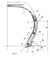
- FIG. 1 shows a partial view of a cross-section of a tire 1 according to the invention, this symmetrical tire and comprising two additional structures 21, 22 for reinforcing the flanks 2 around which are anchored by turning the portions of a reinforcement 3.
- This tire 1 is mounted on its mounting rim J comprising a rim seat S extended axially and radially outwards by a rim flange R whose radially outermost points are on a circle of diameter Dc.
- the tire 1 has a height H of section measured, in the plane of section, between the nominal diameter of the rim Dj (taken substantially at the intersection of the rim R. and the rim seat S) and the point M radially the outermost of the tread.
- This tire has a section width S measured between the points of the axially furthest flanks.
- the tire has a shape ratio equal to 0.70.
- the tire 1 shown schematically comprises a portion forming the crown 4 of the tire, this portion reinforced by a crown reinforcement 41 being provided radially on the outside with a tread 5 intended to come into contact with the roadway during taxiing. .
- a crown reinforcement 41 being provided radially on the outside with a tread 5 intended to come into contact with the roadway during taxiing.
- Extending this vertex 4 is the flank 2 which ends at its radially inner end by a bead 6 intended to come into contact with the mounting rim J of the tire.
- said tire comprises a so-called carcass reinforcement 3 extending from the top to the beads through the sidewalls.
- a first portion 30 of the carcass reinforcement is anchored around an annular bead reinforcement structure 60 (in the form of a metal rod) by passing axially from the inside of the tire outwards to form a 300.
- the internal diameter D 0 of this bead wire 60 is smaller than the outside diameter of the rim flange R (corresponding in this case to the maximum diameter Dc of the rim) so as to hold the bead in place on the rim. mounting.
- a second portion 31 of the same carcass reinforcement extends throughout the entire vertex and partially in the sidewall until it is wound around an additional annular reinforcing structure 21 by passing axially from the inside of the tire towards the inside.
- the outer annular structure 21 is here a metal rod of smaller cross-section than that of the bead wire 60 and of internal diameter D1. This diameter is greater than the outside diameter Dc of the rim flange R; the difference between the internal diameter D1 and the diameter Dj of the seat of the rim is greater than 20% of the diameter Dj.
- a third and last portion 32 of the same carcass reinforcement extends throughout the vertex and partially in the sidewall until it is wrapped around a second additional annular reinforcement structure 22 passing axially from the inside of the pneumatically outwardly to form a turnaround 320.
- the second annular structure additional 22 is here a metal rod identical to the first additional annular structure 21 and internal diameter D2 which in the present case is such that the difference (D2-D1) is substantially equal to the difference (D1-D0).
- the difference between the internal diameter D2 and the diameter Dj of the seat of the rim is equal to 1.2 times the section height H of the tire.
- each first and second carcass reinforcement portion are respectively engaged between the first and second additional annular structures 21 and 22 so as to ensure good mechanical coupling of said reinforcement portions.
- the additional annular flank structures are positioned on either side of the point F of the sidewall of greater width on the section shown.
- One of the important points of this construction is to be able to distribute the forces in the carcass reinforcement between the different annular reinforcement structures so that the circumferential tension forces in each additional flank structure is at least equal to 10% of the circumferential force supported by the bead rod inflation at the pressure of use.
- the sum of the forces taken up by all the additional reinforcement structures of a flank 21, 22 is at least equal to the circumferential force supported by the bead wire 60.
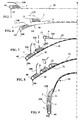
- turns 310 and 320 of the first and second portions 31 and 32 of the carcass reinforcement 3 (respectively anchored on the bead wire and the flank rod radially closest to the rim) follow the axially outer faces of said sections 7 and 8 before partially overlapping the rollover portion of the carcass reinforcement portion radially closest (respectively 310 and 320).
- the flange rods 21 and 22 used in the variants of FIGS. 1 and 2 can easily be replaced by any annular structure having a circumferential extension module such that the force recovery of each of said flange rods is at least 10 mm. % of the circumferential force exerted on the bead wire.
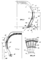
- At least one of the annular structures may be replaced by a structure formed of a series of circumferentially wound wires or cables to form substantially radially oriented cells as shown in the variants of FIGS. 3 and 4.
- each of the annular bead reinforcement structures 60 'and flank 21' and 22 ' is formed of at least two stacks of wire ropes.
- a first structure 60 'in the bead consists of four stacks 600' enclosing a first carcass reinforcement portion 30 '3', this first structure being located radially below the diameter Dc of the rim flange when the tire is mounted on said rim.
- the internal diameter of this first structure is denoted D0 ' .
- the internal diameters of the annular reinforcing structures 21 ', 22', 23 ', denoted respectively D1', D2 ', D3' and the diameter D0 ' of the bead structure 60' are such that the distances between these structures on the section of Figure 3 are substantially equal.
- the stacks of the additional annular structures 21 ', 22', 23 'for reinforcing the flanks are placed axially on either side of all the portions 30', 31 ', 32', 33 ' carcass reinforcement.
- the annular structure 23 ', of diameter D3 ', radially outermost is formed of two stacks between which pass the four carcass reinforcement portions.
- tire architectures are applicable to tires of all categories and in particular for passenger vehicles and particularly high speed vehicles but also tires for heavy goods vehicles, for two wheels, for civil engineering machines, plane.
- tires can be manufactured with processes involving core fabrication.
- some of the reinforcements 111 of the same ply 11 forming a carcass reinforcement may be anchored on a first annular structure 40 and other reinforcements 112, 113 of the same ply 11 may the being respectively on two other annular structures 41 and 42 (the view of Figure 10 corresponds to a partial view of a sidewall).
- FIGS. 5 to 9 show a succession of manufacturing steps of a tire blank comprising a carcass reinforcement 3 anchored to a bead wire 6 in each bead and to two rods 21, 22 in each of the sidewalls of the tire.
- This manufacture substantially corresponds to the tire according to the invention described with the support of FIG.
- a first carcass portion 30 is placed on a drum (only half of said portion is represented here without explicitly showing said drum), then a first rubber compound section 7 is wound on this first portion near each lateral end of said portion and then a bead wire 60 of diameter D0 is threaded concentrically to the drum to come into lateral contact with said first section 7.
- the end portion of this carcass portion is partially returned around the rod 60 while reserving a portion of the turnaround 300 to be plated in a next step on a second carcass portion.
- this first carcass reinforcement portion 30 is assembled with a second portion 31 made on another drum (or on the same drum after conformation to the desired diameter) in the same manner as said first portion.
- This second portion 31 of carcass comprises a portion of the carcass reinforcement partially wound around a rod 21 of internal diameter D1, itself in lateral contact with a second rubber compound profile 8.
- the assembly is made by conforming slightly the first portion of carcass 30 concentrically to the second portion 31 and axially bringing closer the bead rods 60 (towards the median plane marked XX in Figures 5 to 9).
- the next step (FIG. 7) is identical to the previous step in that a third carcass portion 32 is constituted. This third portion 32 wraps around a rod 22 of internal diameter D2 and a third section 9 of rubber mixture.
- the bead and flange rods are brought axially towards the median plane of the tire blank while conforming this blank, for example by internal inflation, according to known means.
- a tire blank 10 is obtained (FIG. 9) in the form of a torus, the turns 300 and 310 of the first and second carcass reinforcement portions being pressed against the rubber sections 7, 8 and 9. .
- the manufacture of the tire is continued, by application, in a manner known per se, of the plies of a reinforcing belt and then of a tread before placing this blank inside a molding mold and vulcanizing rubber mixtures.
Landscapes
- Engineering & Computer Science (AREA)
- Mechanical Engineering (AREA)
- Tires In General (AREA)
- Tyre Moulding (AREA)
- Manufacture Of Alloys Or Alloy Compounds (AREA)
- Processing And Handling Of Plastics And Other Materials For Molding In General (AREA)
- Yarns And Mechanical Finishing Of Yarns Or Ropes (AREA)
Abstract
Description
La présente invention concerne les pneumatiques et plus particulièrement la structure de renforcement des flancs des pneumatiques.The present invention relates to tires and more particularly to the reinforcing structure of the tire sidewalls.
On rappelle qu'un pneumatique, notamment destiné à équiper un véhicule de tourisme, comprend :
- des bourrelets destinés à coopérer avec une jante de montage du pneumatique, lesdits bourrelets comprenant au moins une structure annulaire de renforcement ;
- un sommet comprenant une structure de renforcement comportant une pluralité de renforts comme des câbles ou des fils noyés dans des mélanges de caoutchouc, ce sommet étant surmonté radialement vers l'extérieur par une bande de roulement dont la fonction est d'assurer le contact en roulage avec la chaussée ;
- de part et d'autre du sommet du pneumatique, un flanc assurant la liaison avec chaque bourrelet.
- beads intended to cooperate with a mounting rim of the tire, said beads comprising at least one annular reinforcing structure;
- a crown comprising a reinforcing structure comprising a plurality of reinforcements such as cables or wires embedded in rubber mixtures, this crown being surmounted radially outwards by a tread whose function is to ensure rolling contact with the pavement;
- on either side of the top of the tire, a flank ensuring the connection with each bead.
En outre, un pneumatique comprend une armature de carcasse formée d'une pluralité de renforts (câbles, fils notamment) noyés dans un mélange de caoutchouc, lesdits renforts étant orientés dans des directions préférentielles. Par exemple, les renforts de l'armature de carcasse, sous la forme d'une ou plusieurs nappes, peuvent être disposés de manière à faire un angle proche ou égal à 90° avec la direction circonférentielle sur le pneumatique ; d'autres possibilités connues consistent à disposer ces renforts sur plusieurs nappes de carcasse, les renforts de chaque nappe étant sensiblement parallèles les uns aux autres et faisant un angle différent de 90° avec la direction circonférentielle tout en étant croisés avec les renforts de chaque nappe de carcasse adjacente. Les renforts de l'armature de carcasse peuvent être répartis dans le pneumatique sans pour autant former des nappes (ou couches) en étant par exemple posés de manière individuelle ou par bande de plusieurs renforts parallèles les uns aux autres dans ladite bande.In addition, a tire comprises a carcass reinforcement formed of a plurality of reinforcements (cables, wires in particular) embedded in a rubber mixture, said reinforcements being oriented in preferential directions. For example, reinforcements of the carcass reinforcement, in the form of one or more plies, can be arranged to make an angle close to or equal to 90 ° with the circumferential direction on the tire; other known possibilities are to have these reinforcements on several carcass plies, the reinforcements of each ply being substantially parallel to each other and making an angle different from 90 ° with the circumferential direction while being crossed with the reinforcements of each ply adjacent carcass. Reinforcements of the carcass reinforcement may be distributed in the tire without forming webs (or layers) being for example placed individually or by a strip of several reinforcements parallel to each other in said strip.
En général, l'armature de carcasse s'étend dans le sommet du pneumatique et dans chaque flanc pour s'ancrer sur la structure annulaire de renforcement de chaque bourrelet. Une possibilité consiste à ancrer l'armature de carcasse formée d'une nappe de carcasse par enroulement partiel autour de ladite structure annulaire.In general, the carcass reinforcement extends in the crown of the tire and in each flank to anchor on the annular reinforcing structure of each bead. One possibility is to anchor the carcass reinforcement formed of a carcass ply by partial winding around said annular structure.
Dans le cas de pneumatiques d'indice de vitesse correspondant à des vitesses maximales d'usage très élevées (par exemple supérieures à 240 km/h), il a été proposé des armatures de carcasse comprenant plusieurs nappes de carcasse, l'une au moins desdites nappes étant ancrée par enroulement partiel autour d'une structure annulaire de renforcement en formant un retournement et l'une au moins des nappes de carcasse étant ancrée dans le même bourrelet par couplage mécanique sur ledit retournement en passant ensuite radialement à l'intérieur de la structure annulaire de renforcement.In the case of tires with a speed index corresponding to very high maximum speeds of use (for example greater than 240 km / h), it has been proposed carcass reinforcement comprising several carcass plies, at least one said plies being anchored by partial winding around an annular reinforcing structure forming a reversal and at least one carcass ply being anchored in the same bead by mechanical coupling on said upturn, then passing radially inside the the annular reinforcement structure.
Cette dernière architecture présente un intérêt certain pour ces pneumatiques en ce qu'elle confère une plus grande rigidité aux flancs des pneumatiques et permet d'augmenter sensiblement les performances en virage à grande vitesse.The latter architecture is of interest for these tires in that it gives greater rigidity to the tire sidewalls and substantially increases the performance in high speed cornering.
Une autre famille de solutions consiste à combiner à une armature de carcasse la présence d'armatures supplémentaires d'éléments croisés dans au moins un des flancs.Another family of solutions consists in combining with a carcass reinforcement the presence of additional reinforcements of crossed elements in at least one of the flanks.
Le brevet US 2 186 178, dans le but de conférer au pneumatique, plus particulièrement à armature de carcasse radiale (c'est-à-dire dont les renforts font un angle égal à ou proche de 90° avec la direction circonférentielle), une plus grande stabilité en roulage sans cependant pénaliser le confort, propose de disposer à la jonction entre bourrelet et flanc du pneumatique une tringle additionnelle ou secondaire servant d'ancrage à des structures additionnelles de renforcement. US Pat . No. 2,186,178 , for the purpose of conferring on the tire, more particularly on the radial carcass reinforcement (that is to say the reinforcements forming an angle equal to or close to 90 ° with the circumferential direction), a greater stability in rolling without penalizing comfort, proposes to have at the junction between the bead and sidewall of the tire an additional or secondary rod serving to anchor additional reinforcement structures.
Le brevet FR 1 590 025 reprend sensiblement le même principe en le perfectionnant par l'apport d'un profil d'armature de carcasse adapté dans le flanc de pneumatique. Dans le pneumatique monté sur sa jante de service et gonflé à sa pression nominale, la portion d'armature de carcasse adjacente à la bande de roulement s'étend jusqu'au-delà de la mi-hauteur de flanc en s'écartant progressivement du plan médian et présentant un profil méridien relativement peu incurvé, alors que la seconde portion intercalée radialement entre la première portion et la tringle d'ancrage d'armature de carcasse a une hauteur radiale réduite et un profil méridien relativement très incurvé, les deux portions décrites étant jointes par un deuxième renfort circonférentiel sous forme de tringle. Le même principe d'une tringle additionnelle placée à la jonction du flanc et du bourrelet est repris par le brevet DE 2 357 265. Patent FR 1 590 025 substantially repeats the same principle by improving it by providing a suitable carcass reinforcement profile in the tire sidewall. In the tire mounted on its service rim and inflated to its nominal pressure, the carcass reinforcement portion adjacent to the tread extends beyond mid-flank height away from the median plane and having a relatively low curvature meridian profile, while the second portion radially interposed between the first portion and the carcass reinforcement anchoring rod has a reduced radial height and a relatively highly curved meridian profile, the two portions described being joined by a second circumferential reinforcement in the form of a bead wire. The same principle of an additional rod placed at the junction of the sidewall and the bead is taken up by the
Dans le brevet FR 2 277 688, il a été proposé une structure conférant aux flancs une plus grande résistance aux déformations subies à haute vitesse. Selon ce document, il est proposé un pneumatique dont le sommet comprend une nappe additionnelle, située entre l'armature de carcasse et les nappes de sommet, dont les extrémités axiales sont repliées autour d'un anneau circonférentiel de fil ou câble.In
Dans une demande de brevet publiée sous le numéro WO 02/09955, il a été proposé un pneumatique ayant de grandes performances, en augmentant les rigidités transversale et longitudinale d'au moins un des flancs basée sur ledit principe d'anneau de renforcement additionnel dans au moins un flanc. En outre, cet anneau de renforcement additionnel de flanc situé axialement à l'intérieur de la nappe de carcasse dite axialement extérieure est combiné à la présence d'un profilé de mélange caoutchouteux radialement situé entre ledit élément d'ancrage de bourrelet et ledit anneau de flanc, et axialement situé à l'intérieur de la nappe de carcasse dite axialement à l'extérieur.
Un pneumatique conforme au préambule de la revendication 1 est décrit dans le document JP 03 169 726 A.In a patent application published under the number WO 02/09955, it has been proposed a tire having high performance, by increasing the transverse and longitudinal stiffnesses of at least one of the sidewalls based on said reinforcing ring principle additional in at least one flank. In addition, this additional sidewall reinforcement ring located axially inside the so-called axially outer carcass ply is combined with the presence of a rubber mix profile radially located between said bead anchor element and said bead ring. flank, and axially located inside the carcass ply said axially outside.
A tire according to the preamble of claim 1 is described in JP 03 169 726 A.
Si ces diverses solutions techniques permettent une augmentation notable des performances à hautes vitesses, il a été constaté qu'un besoin d'amélioration existait encore et en particulier pour des pneumatiques dont le rapport de section était supérieur à 40%(le rapport de section noté H/S, est égal au rapport entre la hauteur radiale de section du pneumatique et la largeur hors tout du pneumatique, ces grandeurs étant mesurées lorsque le pneumatique est monté sur sa jante de montage et gonflé à sa pression nominale telles que définies dans la norme ETRTO).While these various technical solutions allow a noticeable increase in performance at high speeds, it was found that a need for improvement still existed and in particular for tires with a section ratio greater than 40% (the section report noted H / S, is equal to the ratio between the radial section height of the tire and the overall width of the tire, these quantities being measured when the tire is mounted on its mounting rim and inflated to its nominal pressure as defined in the standard ETRTO).
En vue d'améliorer significativement le comportement à vitesse élevée (et entre autres, pour diminuer le plus possible les déformations liées à cette vitesse pouvant apparaître dans les flancs) d'un pneumatique et notamment, mais pas exclusivement, celui d'un pneumatique ayant un rapport H/S supérieur ou égal à 40%, il est proposé un pneumatique, prévu pour être monté sur une jante de montage de diamètre maximal Dc, et comprenant :
- des bourrelets destinés à coopérer avec la jante de montage du pneumatique, lesdits bourrelets comprenant au moins une structure annulaire de renforcement ;
- un sommet comprenant une structure de renforcement comportant une pluralité de renforts comme des câbles ou des fils noyés dans des mélanges de caoutchouc, ce sommet étant surmonté radialement vers l'extérieur par une bande de roulement dont la fonction est d'assurer le contact en roulage avec la chaussée ;
- de part et d'autre du sommet du pneumatique, un flanc assurant la liaison avec chaque bourrelet ;
- une armature de carcasse s'étendant entre le sommet et les bourrelets et destinée à équilibrer les efforts dus à la pression de gonflage et à transmettre à la jante via les bourrelets les efforts auxquels est soumis le sommet ; et dont:
- au moins un flanc comprend au moins deux structures annulaires additionnelles de renforcement, chaque structure annulaire additionnelle ayant un diamètre interne au moins égal au diamètre maximal Dc de la jante de montage du pneumatique ; et
- l'armature de carcasse est ancrée au moins partiellement sur chaque structure annulaire de renforcement de bourrelet et sur chaque structure annulaire additionnelle de renforcement de flanc de manière à créer un effort de tension circonférentiel dans chaque structure annulaire dès le gonflage du pneumatique.
- beads intended to cooperate with the tire mounting rim, said beads comprising at least one annular reinforcing structure;
- a crown comprising a reinforcing structure comprising a plurality of reinforcements such as cables or wires embedded in rubber mixtures, this crown being surmounted radially outwards by a tread whose function is to ensure rolling contact with the pavement;
- on either side of the top of the tire, a flank ensuring the connection with each bead;
- a carcass reinforcement extending between the top and the beads and intended to balance the forces due to the inflation pressure and to transmit to the rim via the beads the forces to which the top is subjected; and which:
- at least one flank comprises at least two additional annular reinforcement structures, each additional annular structure having an internal diameter at least equal to the maximum diameter Dc of the tire mounting rim; and
- the carcass reinforcement is anchored at least partially on each annular bead reinforcement structure and on each additional annular flank reinforcement structure so as to create a circumferential tension force in each annular structure upon inflation of the tire.
Par diamètre maximal Dc de la jante de montage, on entend le diamètre du cercle sur lequel se trouvent les points de la jante radialement les plus éloignés de l'axe de rotation. Par exemple, pour une jante usuelle pourvue de rebords de jante sur ses bords latéraux, le diamètre Dc de la jante correspond au diamètre du cercle passant par les points radialement à l'extérieur desdits rebords.By maximum diameter Dc of the mounting rim means the diameter of the circle on which are the points of the rim radially furthest from the axis of rotation. For example, for a common rim provided with rim flanges on its side edges, the diameter Dc of the rim corresponds to the diameter of the circle passing through the points radially outside said flanges.
Par structure annulaire, on entend une structure qui, dans le pneumatique, est capable de supporter un effort de tension circonférentiel supérieur à l'effort qui serait supporté par le même volume de mélange de caoutchouc. On peut notamment employer comme structure annulaire :
- une tringle de type tressée formée d'un ou de plusieurs fils ou câbles métalliques ou textiles ou tout type de structure d'ancrage usuelle de bourrelet ;
- un anneau en matériau métallique, plastique de géométrie de section appropriée ;
- une pluralité de tronçons de fils ou câbles liés entre eux pendant le moulage et la vulcanisation du mélange de caoutchouc enrobant lesdits tronçons.
- a braided type rod formed of one or more son or cables or metal or textile or any type of usual bead anchor structure;
- a ring of metal material, plastic geometry section appropriate;
- a plurality of sections of wires or cables interconnected during molding and vulcanization of the rubber mixture encasing said sections.
Par diamètre interne d'une structure annulaire additionnelle, on entend le diamètre du cercle passant par les points de ladite structure radialement les plus à l'intérieur.
Le pneumatique conforme à l'invention est caractérisé en ce que:By internal diameter of an additional annular structure is meant the diameter of the circle passing through the points of said radially innermost structure.
The tire according to the invention is characterized in that:
la différence entre le diamètre interne de la structure annulaire additionnelle de renforcement radialement la plus à l'intérieur de chaque flanc et le diamètre Dj du siège de jante du même côté que le flanc contenant ladite structure annulaire est au moins égale à 20 % du diamètre Dj.the difference between the inner diameter of the additional radially innermost reinforcing reinforcing structure of each sidewall and the diameter Dj of the rim seat on the same side as the sidewall containing said annular structure is at least equal to 20% of the diameter. Dj .
Préférentiellement, la différence entre le diamètre interne de la structure annulaire additionnelle de chaque flanc radialement la plus à l'extérieur et le diamètre Dj du siège de jante du même côté que le flanc contenant ladite structure annulaire est au plus égal à 1.6 fois la hauteur de section H du pneumatique mesurée sur ce même côté.Preferably, the difference between the internal diameter of the additional annular structure of each radially outermost flank and the diameter Dj of the rim seat on the same side as the flank containing said annular structure is at most equal to 1.6 times the height. of section H of the tire measured on the same side.
Dans une autre variante préférentielle, les structures annulaires additionnelles voisines d'un même flanc, prises deux à deux, sont séparées par un profilé de gomme dont la hauteur, mesurée dans le sens radial, est au moins égale à 15 mm afin d'optimiser le comportement du pneu face à des efforts latéraux importants.In another preferred embodiment, the additional annular structures adjacent to the same sidewall, taken in pairs, are separated by a rubber profile whose height, measured in the radial direction, is at least 15 mm in order to optimize the behavior of the tire in the face of significant lateral forces.
Selon l'invention, l'armature de carcasse peut être ancrée soit en totalité soit seulement de façon partielle à une quelconque des structures annulaires de renforcement de bourrelet ou de flanc.According to the invention, the carcass reinforcement may be anchored either wholly or only partially to any of the annular bead or flank reinforcement structures.
Chaque structure annulaire additionnelle de renforcement est prévue pour reprendre une partie de la tension totale de carcasse lorsque le pneumatique est monté sur sa jante et gonflé à sa pression d'utilisation. Ainsi, il a été trouvé qu'une tension circonférentielle au moins égale à 10% de la tension de la structure de renforcement de bourrelet était préférable.Each additional annular reinforcement structure is provided to take back part of the total carcass tension when the tire is mounted on its rim and inflated to its operating pressure. Thus, it has been found that a circumferential tension of at least 10% of the tension of the bead reinforcement structure is preferable.
Dans une autre variante préférentielle, on peut en outre employer dans un même flanc deux structures additionnelles de même diamètre, ces structures étant décalées axialement, une partie au moins de l'armature de carcasse étant ancrée sur au moins une desdites structures additionnelles.In another preferred embodiment, two additional structures of the same diameter may also be used in the same sidewall, these structures being axially offset, at least a portion of the carcass reinforcement being anchored on at least one of said additional structures.
Préférentiellement, la somme des efforts circonférentiels repris par les structures annulaires de flanc est au moins égale à l'effort circonférentiel auquel est soumis la structure de renforcement de bourrelet.Preferably, the sum of the circumferential forces taken up by the annular flank structures is at least equal to the circumferential force to which the bead reinforcement structure is subjected.
Il est possible à la personne du métier de déterminer la répartition des efforts circonférentiels dans chacune des structures annulaires de renforcement de flanc ; toutefois, il a été constaté de manière surprenante qu'il pouvait être avantageux de faire en sorte que lesdits efforts aillent en augmentant avec le diamètre de la structure annulaire de renforcement de flanc.It is possible for the person skilled in the art to determine the distribution of the circumferential forces in each of the annular flank reinforcement structures; however, it has been surprisingly found that it may be advantageous to cause said forces to increase with the diameter of the annular flank reinforcement structure.
Préférentiellement, chaque portion d'armature de carcasse ancrée sur chaque structure annulaire de renforcement de flanc et de bourrelet forme un retournement, chaque retournement d'une portion d'armature de carcasse étant couplé mécaniquement à au moins une autre portion d'armature ancrée sur une structure annulaire de renforcement de diamètre plus grand.Preferably, each carcass reinforcement portion anchored on each annular flank and bead reinforcement structure forms a reversal, each inversion of a carcass reinforcement portion being mechanically coupled to at least one other portion of reinforcement anchored to an annular reinforcement structure of larger diameter.
Avantageusement, dans ce dernier cas, il est prévu radialement à l'extérieur de chaque structure annulaire de renforcement un profilé de remplissage en mélange de caoutchouc ayant une dureté shore A au moins égal(e) à 50, ce profilé assurant un couplage mécanique entre la portion d'armature de carcasse ancré sur ladite structure et le retournement de ladite portion. Ces profilés peuvent en outre être de nature et/ou de caractéristique mécanique différente en fonction de la position dans un même flanc.Advantageously, in the latter case, there is provided radially outside each annular reinforcing structure a rubber compound filling profile having a shore hardness A at least equal to 50, this section ensuring a mechanical coupling between the carcass reinforcement portion anchored on said structure and the reversal of said portion. These profiles may also be of a different nature and / or mechanical characteristic depending on the position in the same sidewall.
La présence combinée de structures annulaires de renforcement et des profilés de mélange caoutchouteux ayant une dureté Shore A au moins égale à 50 augmente de manière très sensible la résistance aux efforts transversaux.The combined presence of annular reinforcing structures and rubber mix profiles having a Shore A hardness of at least 50 substantially increases the resistance to transverse stresses.
De préférence, lorsque l'une au moins des portions d'armature est retournée autour d'une structure annulaire de renforcement, le retournement formé par ladite portion est situé axialement à l'extérieur d'au moins la structure annulaire de renforcement radialement à l'extérieur la plus proche.Preferably, when at least one of the reinforcement portions is turned around an annular reinforcing structure, the upturn formed by said portion is located axially outside of at least the annular reinforcing structure radially to the nearest outside.
Dans une autre variante de solution, chaque portion de l'armature de carcasse est ancrée par couplage de cisaillement à au moins une structure annulaire de renforcement formée de renforts inextensibles disposés selon au moins une pile dans la direction radiale sur le pneumatique. Préférentiellement, dans cette variante, chaque structure annulaire de renforcement est constituée par au moins deux piles de renforts essentiellement circonférentiels, la portion d'armature de carcasse ancrée sur chaque structure annulaire étant placée axialement entre deux desdites piles.In another alternative solution, each portion of the carcass reinforcement is anchored by shear coupling to at least one annular reinforcing structure formed of inextensible reinforcements arranged in at least one stack in the radial direction on the tire. Preferably, in this variant, each annular reinforcing structure is constituted by at least two substantially circumferential reinforcing stacks, the carcass reinforcement portion anchored on each annular structure being placed axially between two of said stacks.
Afin de fabriquer un pneumatique comprenant, outre une structure annulaire de renforcement circonférentiel de bourrelet, au moins une structure annulaire additionnelle de flanc, le procédé comprend les étapes suivantes :
- on enroule sur un tambour de confection déformable radialement, une première portion de carcasse constituant à terme une partie de l'armature de carcasse ;
- on place de façon à être concentrique à ce tambour et radialement sur l'extérieur à cette première portion une structure annulaire indéformable circonférentiellement de diamètre interne D0 combinée à un profilé de mélange de caoutchouc pour former une structure annulaire de renforcement de bourrelet ;
- on ancre au moins partiellement sur chacune de ces structures annulaires, une extrémité de ladite portion ;
- on prépare sur un diamètre supérieur à D0, une autre portion de l'armature de carcasse du pneumatique, et on place de façon concentrique à cette deuxième portion une structure annulaire de renforcement de diamètre interne D1, D1 étant supérieur à D0 de manière à pouvoir ancrer cette deuxième portion d'armature de carcasse sur ces structures annulaires de renforcement ;
- on répète l'opération précédente autant de fois que nécessaire, c'est-à-dire autant de fois que de structures annulaires de renforcement dans le ou les flanc(s) ; puis,
- on place de façon concentrique les unes aux autres les portions d'armature de carcasse ainsi constituées par diamètres de structure annulaire de renforcement croissants pour constituer un empilement ;
- on force, à l'aide de moyens appropriés connus, l'empilement ainsi obtenu à prendre une forme de tore par expansion radiale et rapprochement transversal des structures annulaires de renforcement ;
- on achève la fabrication du pneumatique de façon usuelle bien connue de l'homme du métier.
- is wound on a radially deformable forming drum, a first carcass portion eventually constituting a portion of the carcass reinforcement;
- concentric with this drum and radially on the outside of this first portion is a circumferentially dimensionally stable annular structure of internal diameter D0 combined with a rubber mixing profile to form an annular bead reinforcing structure;
- anchoring at least partially on each of these annular structures, an end of said portion;
- a further portion of the carcass reinforcement of the tire is prepared on a diameter greater than D0, and an annular reinforcement structure of internal diameter D1 is set concentrically to this second portion , D1 being greater than D0 so as to be able to anchoring this second carcass reinforcement portion on these annular reinforcing structures;
- the preceding operation is repeated as many times as necessary, that is to say as many times as annular reinforcement structures in the flank (s); then,
- the carcass reinforcement portions thus constituted by reinforcing annular reinforcing structure diameters are arranged in a concentric manner to constitute a stack;
- the stack thus obtained is forced, using appropriate known means, into a torus shape by radial expansion and transversal approaching of the annular reinforcement structures;
- the manufacture of the tire is completed in the usual manner well known to those skilled in the art.
Ce procédé donne une grande liberté dans la disposition des différentes portions d'armature de carcasse, de manière à former le pneumatique voulu. Les différentes portions d'armature de carcasse peuvent être disposées de façon symétrique ou non par rapport au plan médian du pneumatique tout en étant concentriques les unes par rapport aux autres.This method gives a great freedom in the arrangement of the various portions of carcass reinforcement, so as to form the desired tire. The various portions of carcass reinforcement may be arranged symmetrically or non-symmetrically with respect to the median plane of the tire while being concentric with each other.
Le procédé qui vient d'être décrit peut avoir des variantes équivalentes. En particulier, l'opération de mise en forme peut être réalisée en une ou plusieurs étapes successives. Par exemple, on forme les différentes portions d'armature de carcasse sur différents tambour avant de les assembler de manière concentrique les unes aux autres et ensuite de les conformer en forme de tore. Une autre possibilité consiste après chaque formation d'une portion d'armature de carcasse à conformer légèrement celle-ci avant de former une autre portion d'armature sur la surface torique obtenue et ainsi de suite.The process just described may have equivalent variants. In particular, the shaping operation can be performed in one or more successive steps. For example, the different carcass reinforcement portions are formed on different front drum to assemble them concentrically to each other and then to conform them to the shape of a torus. Another possibility is after each formation of a carcass reinforcement portion to slightly conform it before forming another reinforcing portion on the toric surface obtained and so on.
Dans toutes ces variantes du procédé, les retournements de chaque portion d'armature de carcasse autour des structures annulaires de renforcement peuvent être placés soit radialement vers l'intérieur desdites structures annulaires soit radialement vers l'extérieur desdites structures.In all these variants of the method, the turns of each carcass reinforcement portion around the annular reinforcement structures may be placed either radially inwardly of said annular structures or radially outwardly of said structures.
Le procédé décrit s'applique à la formation d'un pneumatique dans lequel l'armature de carcasse est ancrée, outre dans les bourrelets, à au moins une autre structure additionnelle de diamètre plus grand que le diamètre de la structure de renforcement des bourrelets.The described method applies to the formation of a tire in which the carcass reinforcement is anchored, in addition to the beads, to at least one other additional structure of diameter larger than the diameter of the bead reinforcement structure.
Ce procédé permet un excellent positionnement des diverses structures annulaires de renforcement les unes par rapport aux autres dans la direction radiale assurant ainsi, par un très bon centrage, une très bonne uniformité de roulage.This method allows an excellent positioning of the various annular reinforcing structures relative to each other in the radial direction thus ensuring, by a very good centering, a very good uniformity of rolling.
D'autres caractéristiques et avantages de la présente addition apparaîtront au cours de la description qui va suivre, en référence aux dessins annexés dans lesquels
- la figure 1 représente une vue partielle en coupe radiale d'un pneumatique conforme à l'invention ;
- les figures 2 à 4 montrent diverses variantes de pneumatiques selon l'invention ;
- les figures 5 à 9 montrent les étapes d'un procédé de fabrication d'une armature de carcasse pour un pneumatique selon l'invention comprenant deux structures annulaires de renforcement dans chaque flanc ;
- la figure 10 représente une vue partielle du flanc d'un pneumatique conforme à l'invention.
- Figure 1 shows a partial view in radial section of a tire according to the invention;
- Figures 2 to 4 show various tire variants according to the invention;
- Figures 5 to 9 show the steps of a method of manufacturing a carcass reinforcement for a tire according to the invention comprising two annular reinforcement structures in each sidewall;
- Figure 10 shows a partial view of the sidewall of a tire according to the invention.
La figure 1 montre une vue partielle d'une coupe transversale d'un pneumatique 1 selon l'invention, ce pneumatique symétrique et comprenant deux structures additionnelles 21, 22 de renforcement des flancs 2 autour desquelles sont ancrées par retournement des portions d'une armature de carcasse 3. Ce pneumatique 1 est monté sur sa jante de montage J comprenant un siège de jante S prolongé axialement et radialement vers l'extérieur par un rebord de jante R dont les points radialement les plus à l'extérieur sont sur un cercle de diamètre Dc.FIG. 1 shows a partial view of a cross-section of a tire 1 according to the invention, this symmetrical tire and comprising two
Dans cette configuration, le pneumatique 1 présente une hauteur H de section mesurée, dans le plan de coupe, entre le diamètre nominal de la jante Dj (pris sensiblement à l'intersection du rebord R. et du siège de jante S) et le point M radialement le plus à l'extérieur de la bande de roulement. Ce pneumatique a une largeur de section S mesurée entre les points des flancs axialement les plus éloignés. Dans le cas présent, le pneumatique a un rapport de forme égal à 0.70.In this configuration, the tire 1 has a height H of section measured, in the plane of section, between the nominal diameter of the rim Dj (taken substantially at the intersection of the rim R. and the rim seat S) and the point M radially the outermost of the tread. This tire has a section width S measured between the points of the axially furthest flanks. In this case, the tire has a shape ratio equal to 0.70.
Le pneumatique 1 montré de manière schématique comprend une partie formant le sommet 4 du pneumatique, cette partie renforcée par une armature de sommet 41 étant pourvue radialement à l'extérieur avec une bande de roulement 5 destinée à venir au contact avec la chaussée pendant le roulage. Prolongeant ce sommet 4 se trouve le flanc 2 qui se termine à son extrémité radialement interne par un bourrelet 6 destiné à venir en contact avec la jante de montage J du pneumatique.The tire 1 shown schematically comprises a portion forming the crown 4 of the tire, this portion reinforced by a
En outre et pour équilibrer les efforts dus à la pression interne de gonflage du pneumatique, ledit pneumatique comprend une armature dite de carcasse 3 s'étendant du sommet aux bourrelets en passant par les flancs.In addition and to balance the forces due to the internal tire inflation pressure, said tire comprises a so-called
Une première portion 30 de l'armature de carcasse est ancrée autour d'une structure annulaire 60 de renforcement de bourrelet 6 (sous la forme d'une tringle métallique) en passant axialement de l'intérieur du pneumatique vers l'extérieur pour former un retournement 300. Le diamètre interne D0 de cette tringle 60 de bourrelet est inférieur au diamètre extérieur du rebord R de jante (correspondant dans le cas présent au diamètre maximal Dc de la jante) de manière à assurer le maintien en place du bourrelet sur la jante de montage.A
Une deuxième portion 31 de la même armature de carcasse s'étend dans tout le sommet et partiellement dans le flanc jusqu'à venir s'enrouler autour d'une structure annulaire additionnelle 21 de renforcement en passant axialement de l'intérieur du pneumatique vers l'extérieur pour former un retournement 310. La structure annulaire additionnelle 21 est ici une tringle métallique de section transversale plus petite que celle de la tringle de bourrelet 60 et de diamètre interne D1. Ce diamètre est supérieur au diamètre extérieur Dc du rebord R de jante ; la différence entre le diamètre interne D1 et le diamètre Dj du siège de la jante est supérieure à 20 % du diamètre Dj.A
Une troisième et dernière portion 32 de la même armature de carcasse s'étend dans tout le sommet et partiellement dans le flanc jusqu'à venir s'enrouler autour d'une seconde structure annulaire additionnelle 22 de renforcement en passant axialement de l'intérieur du pneumatique vers l'extérieur pour former un retournement 320. La seconde structure annulaire additionnelle 22 est ici une tringle métallique identique à la première structure annulaire additionnelle 21 et de diamètre interne D2 qui dans le cas présent est tel que la différence (D2-D1) est sensiblement égale à la différence (D1-D0). Dans le cas présent, la différence entre le diamètre interne D2 et le diamètre Dj du siège de la jante est égale à 1.2 fois la hauteur de section H du pneumatique.A third and
On constate que les retournement 310, 320 de chaque première et seconde portion d'armature de carcasse sont respectivement engagés entre les première et seconde structures annulaires additionnelles 21 et 22 de manière à assurer un bon couplage mécanique desdites portions d'armature.It can be seen that the
Dans ce premier exemple, les structures annulaires additionnelles de flanc sont positionnées de part et d'autre du point F du flanc de plus grande largeur sur la coupe représentée.In this first example, the additional annular flank structures are positioned on either side of the point F of the sidewall of greater width on the section shown.
Un des points importants de cette construction est de pouvoir répartir les efforts dans l'armature de carcasse entre les différentes structures annulaires de renforcement de façon que les efforts de tension circonférentielle dans chaque structure additionnelle de flanc soit au moins égal à 10% de l'effort circonférentiel supporté par la tringle de bourrelet au gonflage à la pression d'utilisation.One of the important points of this construction is to be able to distribute the forces in the carcass reinforcement between the different annular reinforcement structures so that the circumferential tension forces in each additional flank structure is at least equal to 10% of the circumferential force supported by the bead rod inflation at the pressure of use.
Avantageusement, la somme des efforts repris par toutes les structures additionnelles de renfort d'un flanc 21, 22 est au moins égale à l'effort circonférentiel supporté par la tringle de bourrelet 60.Advantageously, the sum of the forces taken up by all the additional reinforcement structures of a
Grâce à cette construction, il est possible d'obtenir un pneumatique présentant une plus grande rigidité transversale en roulage et ainsi améliorer de façon très significative les performances en roulage des véhicules équipés de tels pneumatiques. Cette solution présente un intérêt tout particulier à haute vitesse.With this construction, it is possible to obtain a tire having greater transverse rigidity in rolling and thus significantly improve the running performance of vehicles equipped with such tires. This solution is of particular interest at high speed.
Dans une autre variante représentée à la figure 2 (par commodité les mêmes références sont utilisées quand elles désignent des éléments de structure comparables), la construction est sensiblement même que celle montrée avec la figure 1 en ce qui concerne les trois portions d'armature de carcasse (à savoir trois portions ancrées sur une tringle de bourrelet 60 et sur deux structures annulaires additionnelles 21 et 22 de flanc) à la différence près que radialement au delà de la tringle de bourrelet 60 et radialement au delà de la tringle 21 de flanc radialement la plus proche de la jante sont disposés des profilés de mélanges 7 et 8 de caoutchouc de dureté Shore A au moins égale à 50 et dans le cas présent égale à 80. La hauteur du profilé 8, mesurée dans le sens radial est au moins égale à 15 mm et dans le cas présent égale à 20 mm. Ces profilés assurent une bonne liaison mécanique entre les structures annulaires de renforcement 60, 21, 22 et une plus grande rigidité structurelle des parties de flanc concernées.In another variant shown in Figure 2 (for convenience the same references are used when they designate comparable structural elements), the construction is substantially same as that shown in Figure 1 with respect to the three armature portions of carcass (namely three portions anchored on a
Par ailleurs, les retournements 310 et 320 des première et seconde portions 31 et 32 de l'armature de carcasse 3 (ancrées respectivement sur la tringle de bourrelet et la tringle de flanc radialement la plus proche de la jante) suivent les faces axialement extérieures desdits profilés 7 et 8 avant de se superposer partiellement au retournement de la portion d'armature de carcasse radialement la plus proche (respectivement 310 et 320).Furthermore, the
Les tringles 21 et 22 de flanc employées dans les variantes des figures 1 et 2 peuvent aisément être remplacées par toute structure annulaire présentant un module d'extension circonférentiel tel que la reprise d'effort de chacune desdites tringles de flanc soit au moins égale à 10% de l'effort circonférentiel s'exerçant sur la tringle de bourrelet.The
L'une au moins des structures annulaires peut être remplacée par une structure formée d'une série de fils ou câbles enroulés circonférentiellement pour former des piles orientées sensiblement radialement comme cela est montré sur les variantes des figures 3 et 4.At least one of the annular structures may be replaced by a structure formed of a series of circumferentially wound wires or cables to form substantially radially oriented cells as shown in the variants of FIGS. 3 and 4.
Sur la figure 3, chacune des structures annulaires de renforcement de bourrelet 60' et de flanc 21' et 22' est formée d'au moins deux piles de câbles métalliques. Une première structure 60' dans le bourrelet est constituée de quatre piles 600', enserrant une première portion 30' d'armature de carcasse 3', cette première structure étant située radialement au dessous du diamètre Dc du rebord de jante lorsque le pneumatique est monté sur ladite jante. Le diamètre interne de cette première structure est noté D0'.In Fig. 3, each of the annular bead reinforcement structures 60 'and flank 21' and 22 'is formed of at least two stacks of wire ropes. A first structure 60 'in the bead consists of four stacks 600' enclosing a first carcass reinforcement portion 30 '3', this first structure being located radially below the diameter Dc of the rim flange when the tire is mounted on said rim. The internal diameter of this first structure is denoted D0 ' .
En outre trois autres portions 31', 32', 33' de la même armature de carcasse 3' sont ancrées chacune à leur extrémité entre deux piles de câbles enroulés circonférentiellement. Les ancrages des différentes portions de carcasse sont faits sans retournement.In addition three other portions 31 ', 32', 33 'of the same carcass reinforcement 3' are each anchored at their end between two stacks of cables wound circumferentially. The anchors of the different carcass portions are made without turning.
Les diamètres internes des structures annulaires de renfort 21', 22', 23', notés respectivement D1', D2', D3' et le diamètre D0' de la structure de bourrelet 60' sont tels que les distances entre ces structures sur la coupe de la figure 3 soient sensiblement égales.The internal diameters of the annular reinforcing structures 21 ', 22', 23 ', denoted respectively D1', D2 ', D3' and the diameter D0 ' of the bead structure 60' are such that the distances between these structures on the section of Figure 3 are substantially equal.
Dans la variante de la figure 4, les piles des structures annulaires additionnelles 21', 22', 23' de renforcement des flancs sont placées axialement de part et d'autre de toutes les portions 30', 31', 32', 33' d'armature de carcasse. Par exemple, la structure annulaire 23', de diamètre D3', radialement la plus à l'extérieur est formée de deux piles entre lesquelles passent les quatre portions d'armature de carcasse.In the variant of FIG. 4, the stacks of the additional annular structures 21 ', 22', 23 'for reinforcing the flanks are placed axially on either side of all the portions 30', 31 ', 32', 33 ' carcass reinforcement. For example, the annular structure 23 ', of diameter D3 ', radially outermost is formed of two stacks between which pass the four carcass reinforcement portions.
Ces architectures de pneumatique sont applicables à des pneumatiques de toutes catégories et notamment destinés à des véhicules de tourisme et particulièrement des véhicules hautes vitesse mais également des pneumatiques destinés à des véhicules de poids lourd, pour deux roues, pour engins de génie civil, d'avion.These tire architectures are applicable to tires of all categories and in particular for passenger vehicles and particularly high speed vehicles but also tires for heavy goods vehicles, for two wheels, for civil engineering machines, plane.
Ces pneumatiques peuvent être fabriqués avec des procédés mettant en oeuvre une fabrication sur noyau.These tires can be manufactured with processes involving core fabrication.
On a montré différentes variantes de pneumatiques se montant sur des jantes dont les sièges sont inclinés vers l'intérieur (c'est-à-dire dont les points axialement les plus à l'extérieur sont situés sur un cercle de diamètre supérieur au diamètre du cercle sur lequel sont situés les points axialement à l'intérieur) ; la personne du métier peut adapter cette invention à des pneumatiques destinés à être montés sur des jantes dont au moins un siège est incliné vers l'extérieur (c'est-à-dire dont les points axialement les plus à l'extérieur sont situés sur un cercle de diamètre inférieur au diamètre du cercle sur lequel sont situés les points axialement à l'intérieur) comme définis par exemple dans le brevet US 6092575. Dans le cas d'un pneumatique monté sur une jante ayant des sièges de diamètres différents, il est avantageux de prévoir un plus grand nombre de structures annulaires de renforcement d'ancrage de carcasse sur le flanc le plus long (c'est-à-dire sur le flanc se prolongeant par le bourrelet en contact avec le siège de jante de plus petit diamètre).Different tire variants have been shown to be fitted on rims whose seats are inclined inwards (that is to say whose axially outermost points are situated on a circle of diameter greater than the diameter of the wheel). circle on which are the points axially inside); the person skilled in the art can adapt this invention to tires intended to be mounted on rims whose at least one seat is inclined outwards (that is to say whose axially outermost points are located on a circle of diameter less than the diameter of the circle on which are the points axially inside) as defined for example in the patent US 6092575. In the case of a tire mounted on a rim having seats of different diameters, It is advantageous to provide a greater number of annular carcass anchoring reinforcement structures on the longer sidewall (i.e. on the sidewall extending by the bead in contact with the smaller rim seat. diameter).
Dans une autre variante, montrée schématiquement avec la figure 10, certains des renforts 111 d'une même nappe 11 formant une armature de carcasse peuvent être ancrés sur une première structure annulaire 40 et d'autres renforts 112, 113 de la même nappe 11 peuvent l'être respectivement sur deux autres structures annulaires 41 et 42 (la vue de la figure 10 correspond à une vue partielle d'un flanc).In another variant, shown schematically with FIG. 10, some of the
Description des étapes du procédéDescription of the process steps
Avec les figures 5 à 9 , on représente une succession d'étapes de fabrication d'une ébauche de pneumatique comprenant une armature de carcasse 3 ancrée à une tringle 6 dans chaque bourrelet et à deux tringles 21, 22 dans chacun des flancs du pneumatique. Cette fabrication correspond sensiblement au pneumatique selon l'invention décrit avec le support de la figure 2.FIGS. 5 to 9 show a succession of manufacturing steps of a tire blank comprising a
Dans une première étape (Fig 5), on pose une première portion 30 de carcasse sur un tambour (on a représenté ici une moitié seulement de ladite portion sans montrer explicitement ledit tambour), puis un premier profilé 7 de mélange de caoutchouc est enroulé sur cette première portion près de chaque extrémité latérale de ladite portion et ensuite une tringle de bourrelet 60 de diamètre D0 est enfilée de façon concentrique au tambour pour venir en contact latéralement avec ledit premier profilé 7. Ensuite, la partie d'extrémité de cette portion de carcasse est partiellement retournée autour de la tringle 60 tout en réservant une partie du retournement 300 pour être plaquée dans une étape suivante sur une deuxième portion de carcasse.In a first step (FIG. 5), a
Dans l'étape suivante (Fig 6), on assemble cette première portion 30 d'armature de carcasse avec une deuxième portion 31 réalisée sur un autre tambour (ou sur le même tambour après conformation au diamètre voulu) de la même manière que ladite première portion. Cette deuxième portion 31 de carcasse comprend une partie de l'armature de carcasse partiellement enroulée autour d'une tringle 21 de diamètre interne D1, elle même en contact latéral avec un deuxième profilé de mélange de caoutchouc 8. L'assemblage est réalisé en conformant légèrement la première portion 30 de carcasse de façon concentrique à la deuxième portion 31 et en rapprochant axialement les tringles de bourrelet 60 (vers le plan médian repéré XX sur les figures 5 à 9).In the next step (FIG. 6), this first
L'étape suivante (Fig 7) est identique à l'étape précédente en ce qu'une troisième portion 32 de carcasse est constituée. Cette troisième portion 32 s'enroule autour d'une tringle 22 de diamètre interne D2 et d'un troisième profilé 9 en mélange de caoutchouc.The next step (FIG. 7) is identical to the previous step in that a
À l'étape montrée avec la figure 8, les tringles de bourrelet et de flanc sont rapprochées axialement vers le plan médian de l'ébauche de pneumatique tout en conformant cette ébauche par exemple par gonflage interne selon des moyens connus.In the step shown in FIG. 8, the bead and flange rods are brought axially towards the median plane of the tire blank while conforming this blank, for example by internal inflation, according to known means.
En dernier lieu, une ébauche 10 de pneumatique est obtenue (Fig 9) sous la forme d'un tore, les retournements 300 et 310 des première et deuxième portions d'armature de carcasse étant plaqués contre les profilés 7, 8 et 9 de caoutchouc.Finally, a tire blank 10 is obtained (FIG. 9) in the form of a torus, the
Après cela, on poursuit la fabrication du pneumatique, par application, de manière en soi connue, des nappes d'une ceinture de renforcement puis d'une bande de roulement avant de mettre cette ébauche à l'intérieur d'un moule de moulage et de vulcanisation des mélanges de caoutchouc.After that, the manufacture of the tire is continued, by application, in a manner known per se, of the plies of a reinforcing belt and then of a tread before placing this blank inside a molding mold and vulcanizing rubber mixtures.
L'invention n'est bien sûr pas limitée aux exemples décrits et représentés et diverses modifications peuvent y être apportées sans sortir de son cadre, tel que défini par les revendications.The invention is of course not limited to the examples described and shown and various modifications can be made without departing from its scope, as defined by the claims.
Claims (8)
- Tyre (1) designed to be mounted on a mounting rim J of maximum diameter Dc the said type comprising:- beads (6) designed to cooperate with seats of the mounting rim, the said beads (6) comprising at least one annular bead reinforcement structure (60);- a crown (4) comprising a reinforcement structure, this crown being surmounted radially on the outside by a tread (5);- on either side of the tyre's crown, a sidewall (2) providing connection to each bead (6);- a carcass reinforcement (3) extending between the crown and the beads;in which:- at least one sidewall (2) comprises at least two additional annular reinforcement structures (21, 22), each additional annular structure having an inner diameter at least equal to the maximum diameter Dc of the rim;- the carcass reinforcement (3) is anchored at least partially on each annular bead reinforcement structure (60) and on each additional annular sidewall reinforcement structure (21, 22);
this tyre being characterised in that:- the difference between the inner diameter of the radially innermost additional reinforcement structure (21) in each sidewall and the diameter Dj of the rim seat on the same side as the said sidewall containing the said annular structure is at least equal to 20% of the diameter Dj. - Tyre (1) according to Claim 1, characterised in that the difference between the inner diameter of the radially outermost additional annular reinforcement structure (22) in each sidewall and the diameter Dj of the rim seat on the same side as the said sidewall containing the said annular structure is at most equal to 1.6 times the section height H of the tyre.
- Tyre (1) according to either of Claims 1 and 2, characterised in that the adjacent additional annular structures (21, 22) in the same sidewall, taken two by two, are separated by a rubber profiled element (8) whose height, measured in the radial direction is at least equal to 15 mm.
- Tyre (1) according to any of Claims 1 to 3, characterised in that the tension force in each additional sidewall structure (21, 22) is at least equal to 10% of the circumferential tension force taken up by the annular bead structure (60) when the tyre is inflated to its working pressure.
- Tyre (1) according to Claim 4, characterised in that the sum of the circumferential forces taken up by the additional annular sidewall structures (21, 22) is at least equal to the circumferential force to which the bead reinforcement structure (60) is subjected when the tyre is inflated to its working pressure.
- Tyre (1) according to any of Claims 1 to 5, characterised in that each of the annular reinforcement structures (60, 21, 22) is a wire to which is anchored a portion of the carcass reinforcement by forming an upturn.
- Tyre (1) according to Claim 6, characterised in that at least between two annular reinforcement structures (60, 21, 22) on the same side of the tyre, a rubber profiled element (7, 8) is provided, whose Shore A hardness is at least equal to 50 and is appropriate for ensuring a proper function of the said profiled element under compression.
- Tyre (1) according to any of Claims 1 to 5, characterised in that each of the annular reinforcement structures (60', 21', 22') is composed of a series of threads or cables arranged in the circumferential direction to form at least one stack extending radially and to which a portion of the carcass reinforcement is anchored.
Applications Claiming Priority (3)
| Application Number | Priority Date | Filing Date | Title |
|---|---|---|---|
| FR0302574 | 2003-03-03 | ||
| FR0302574 | 2003-03-03 | ||
| PCT/EP2004/001910 WO2004078494A1 (en) | 2003-03-03 | 2004-02-26 | Tyre with a reinforced flank and method for the production thereof |
Publications (2)
| Publication Number | Publication Date |
|---|---|
| EP1601539A1 EP1601539A1 (en) | 2005-12-07 |
| EP1601539B1 true EP1601539B1 (en) | 2006-12-27 |
Family
ID=32947093
Family Applications (1)
| Application Number | Title | Priority Date | Filing Date |
|---|---|---|---|
| EP04714757A Expired - Lifetime EP1601539B1 (en) | 2003-03-03 | 2004-02-26 | Tyre with a reinforced flank and method for the production thereof |
Country Status (8)
| Country | Link |
|---|---|
| US (1) | US7278458B2 (en) |
| EP (1) | EP1601539B1 (en) |
| JP (1) | JP4536715B2 (en) |
| CN (1) | CN100391752C (en) |
| AT (1) | ATE349344T1 (en) |
| BR (1) | BRPI0407933A (en) |
| DE (1) | DE602004003917T2 (en) |
| WO (1) | WO2004078494A1 (en) |
Families Citing this family (7)
| Publication number | Priority date | Publication date | Assignee | Title |
|---|---|---|---|---|
| JP4521220B2 (en) * | 2004-05-17 | 2010-08-11 | 株式会社ブリヂストン | Pneumatic tire |
| US20070044889A1 (en) * | 2005-09-01 | 2007-03-01 | Bridgestone Firestone North American Tire, Llc | Tire having a sidewall reinforcement |
| US20100024960A1 (en) * | 2005-09-01 | 2010-02-04 | Bridgestone Americas Tire Operations, Llc | Body ply and insert assembly method |
| FR2911299B1 (en) * | 2007-01-17 | 2009-03-06 | Michelin Soc Tech | ADDITIONAL REINFORCEMENT OF PNEUMATIC FLANGE OF HEAVY WEIGHT |
| EP2318201B1 (en) * | 2008-06-27 | 2019-05-22 | Compagnie Générale des Etablissements Michelin | Patch having reinforcements with staggered ends |
| US9227467B2 (en) * | 2013-07-22 | 2016-01-05 | E I Du Pont De Nemours And Company | Pneumatic tire |
| CN110891802B (en) * | 2017-08-18 | 2022-04-26 | 横滨橡胶株式会社 | Pneumatic tire |
Family Cites Families (19)
| Publication number | Priority date | Publication date | Assignee | Title |
|---|---|---|---|---|
| US1548370A (en) * | 1921-08-12 | 1925-08-04 | Fisk Rubber Co | Tire |
| US2186178A (en) * | 1937-02-11 | 1940-01-09 | Jacob George Smith | Pneumatic tire |
| NL137766C (en) * | 1968-10-25 | |||
| DE2357265A1 (en) * | 1973-11-16 | 1975-05-28 | Continental Gummi Werke Ag | Vehicle tyre with reinforced sidewalls - using strong ring arranged floatingly between carcase and outer face of tyre |
| FR2277688A2 (en) | 1974-07-09 | 1976-02-06 | Uniroyal | Cable reinforcement of folded tyre shoulder stiffening plies - to enhance stiffness of the tyre shoulders |
| US4029137A (en) * | 1975-12-15 | 1977-06-14 | The Goodyear Tire & Rubber Company | Pneumatic tire |
| JPS5984607A (en) * | 1982-11-08 | 1984-05-16 | Sumitomo Rubber Ind Ltd | Pneumatic tire |
| JPS6341208A (en) * | 1986-08-04 | 1988-02-22 | Sumitomo Rubber Ind Ltd | Safety tire |
| JPH03169726A (en) * | 1989-11-30 | 1991-07-23 | Sumitomo Rubber Ind Ltd | Bias tire for high pressure |
| JP3169726B2 (en) * | 1993-01-08 | 2001-05-28 | 株式会社山武 | Arithmetic unit with load circuit |
| FR2707561A1 (en) * | 1993-07-12 | 1995-01-20 | Michelin & Cie | Tire structure for heavy goods vehicles. |
| JPH09207526A (en) * | 1995-10-23 | 1997-08-12 | Sumitomo Rubber Ind Ltd | Air-filled tire |
| FR2773518A1 (en) * | 1998-01-12 | 1999-07-16 | Michelin & Cie | TIRE SADDLE WITH CIRCUMFERENTIAL REINFORCEMENT ELEMENTS |
| DE60021032T2 (en) * | 1999-08-05 | 2006-06-01 | Pirelli Pneumatici S.P.A. | Tires for motor vehicle wheels |
| FR2812240A1 (en) | 2000-07-31 | 2002-02-01 | Michelin Soc Tech | TIRE WITH IMPROVED STRUCTURE SIDES |
| JP4575607B2 (en) * | 2000-10-03 | 2010-11-04 | 不二精工株式会社 | Run-flat tire and assembly of run-flat tire and rim |
| WO2002096674A1 (en) * | 2001-05-31 | 2002-12-05 | Societe De Technologie Michelin | Radial tyre sidewall reinforcement |
| JP3628279B2 (en) * | 2001-06-25 | 2005-03-09 | 横浜ゴム株式会社 | Pneumatic tires for construction vehicles |
| FR2827810A1 (en) * | 2001-07-25 | 2003-01-31 | Michelin Soc Tech | TIRE HAVING DISSYMMETRIC AND REINFORCED SIDES |
-
2004
- 2004-02-26 JP JP2006504476A patent/JP4536715B2/en not_active Expired - Fee Related
- 2004-02-26 BR BRPI0407933-7A patent/BRPI0407933A/en not_active Application Discontinuation
- 2004-02-26 DE DE602004003917T patent/DE602004003917T2/en not_active Expired - Lifetime
- 2004-02-26 WO PCT/EP2004/001910 patent/WO2004078494A1/en active IP Right Grant
- 2004-02-26 AT AT04714757T patent/ATE349344T1/en not_active IP Right Cessation
- 2004-02-26 CN CNB2004800059705A patent/CN100391752C/en not_active Expired - Fee Related
- 2004-02-26 EP EP04714757A patent/EP1601539B1/en not_active Expired - Lifetime
-
2005
- 2005-08-24 US US11/210,649 patent/US7278458B2/en not_active Expired - Fee Related
Also Published As
| Publication number | Publication date |
|---|---|
| CN100391752C (en) | 2008-06-04 |
| EP1601539A1 (en) | 2005-12-07 |
| US20060054260A1 (en) | 2006-03-16 |
| CN1756672A (en) | 2006-04-05 |
| WO2004078494A1 (en) | 2004-09-16 |
| ATE349344T1 (en) | 2007-01-15 |
| US7278458B2 (en) | 2007-10-09 |
| DE602004003917D1 (en) | 2007-02-08 |
| JP2006519131A (en) | 2006-08-24 |
| JP4536715B2 (en) | 2010-09-01 |
| DE602004003917T2 (en) | 2007-10-18 |
| BRPI0407933A (en) | 2006-02-21 |
Similar Documents
| Publication | Publication Date | Title |
|---|---|---|
| EP1648717B1 (en) | Tyre for heavy vehicles | |
| EP1858716B1 (en) | Tyre bead structure | |
| EP2114698B1 (en) | Tyre for heavy vehicles | |
| EP2379348B1 (en) | Vehicle tyre comprising a layer of circumferential reinforcing elements | |
| WO1999048709A1 (en) | Radial tyre reinforced bead | |
| WO1999025572A1 (en) | Tyre bead without bead core | |
| EP1047565A1 (en) | Tyre bead with circumferential reinforcing elements | |
| CA2318327C (en) | Tyre bead with circumferential reinforcing elements | |
| EP1254034B1 (en) | Tyre bead with extended mobility | |
| EP1461215B1 (en) | Double half-carcass tyre with an adapted crown area | |
| EP2429834A1 (en) | Reinforcement comprising two reinforcing materials and tyre comprising such a reinforcement | |
| EP1601539B1 (en) | Tyre with a reinforced flank and method for the production thereof | |
| EP1307349B1 (en) | Tyre with improved structural sidewalls | |
| EP1414655B1 (en) | Tyre with non symmetrical reinforced sidewalls | |
| EP1441915B1 (en) | Double half-carcass tyre with lowered crown reinforcements | |
| FR2935295A1 (en) | TIRE FOR HEAVY VEHICLES COMPRISING AT LEAST ON EACH SHOULDER AT LEAST TWO ADDITIONAL LAYERS IN THE TOP FRAME | |
| EP1789266B1 (en) | Extended mobility tyre comprising several superlow anchor areas | |
| WO2006024561A1 (en) | Extended mobility tyre comprising an anchoring area having a high moment of inertia | |
| EP2219886B1 (en) | Vehicle having tyres with reinforced sidewalls | |
| WO2003093032A1 (en) | Tyre with bead comprising a micro-deformable anchor zone | |
| WO2003093034A2 (en) | Tyre with bead provided with a wire structure divided into two zones | |
| WO2005047027A1 (en) | Tyre with extended mobility comprising dual reinforcement and asymmetric beads | |
| WO2003093033A1 (en) | Tyre with bead provided with a zone facilitating mounting/dismounting |
Legal Events
| Date | Code | Title | Description |
|---|---|---|---|
| PUAI | Public reference made under article 153(3) epc to a published international application that has entered the european phase |
Free format text: ORIGINAL CODE: 0009012 |
|
| 17P | Request for examination filed |
Effective date: 20051004 |
|
| AK | Designated contracting states |
Kind code of ref document: A1 Designated state(s): AT BE BG CH CY CZ DE DK EE ES FI FR GB GR HU IE IT LI LU MC NL PT RO SE SI SK TR |
|
| AX | Request for extension of the european patent |
Extension state: AL LT LV MK |
|
| DAX | Request for extension of the european patent (deleted) | ||
| GRAP | Despatch of communication of intention to grant a patent |
Free format text: ORIGINAL CODE: EPIDOSNIGR1 |
|
| GRAS | Grant fee paid |
Free format text: ORIGINAL CODE: EPIDOSNIGR3 |
|
| GRAA | (expected) grant |
Free format text: ORIGINAL CODE: 0009210 |
|
| AK | Designated contracting states |
Kind code of ref document: B1 Designated state(s): AT BE BG CH CY CZ DE DK EE ES FI FR GB GR HU IE IT LI LU MC NL PT RO SE SI SK TR |
|
| PG25 | Lapsed in a contracting state [announced via postgrant information from national office to epo] |
Ref country code: RO Free format text: LAPSE BECAUSE OF FAILURE TO SUBMIT A TRANSLATION OF THE DESCRIPTION OR TO PAY THE FEE WITHIN THE PRESCRIBED TIME-LIMIT Effective date: 20061227 Ref country code: SK Free format text: LAPSE BECAUSE OF FAILURE TO SUBMIT A TRANSLATION OF THE DESCRIPTION OR TO PAY THE FEE WITHIN THE PRESCRIBED TIME-LIMIT Effective date: 20061227 Ref country code: AT Free format text: LAPSE BECAUSE OF FAILURE TO SUBMIT A TRANSLATION OF THE DESCRIPTION OR TO PAY THE FEE WITHIN THE PRESCRIBED TIME-LIMIT Effective date: 20061227 Ref country code: CZ Free format text: LAPSE BECAUSE OF FAILURE TO SUBMIT A TRANSLATION OF THE DESCRIPTION OR TO PAY THE FEE WITHIN THE PRESCRIBED TIME-LIMIT Effective date: 20061227 Ref country code: SI Free format text: LAPSE BECAUSE OF FAILURE TO SUBMIT A TRANSLATION OF THE DESCRIPTION OR TO PAY THE FEE WITHIN THE PRESCRIBED TIME-LIMIT Effective date: 20061227 Ref country code: DK Free format text: LAPSE BECAUSE OF FAILURE TO SUBMIT A TRANSLATION OF THE DESCRIPTION OR TO PAY THE FEE WITHIN THE PRESCRIBED TIME-LIMIT Effective date: 20061227 Ref country code: IE Free format text: LAPSE BECAUSE OF FAILURE TO SUBMIT A TRANSLATION OF THE DESCRIPTION OR TO PAY THE FEE WITHIN THE PRESCRIBED TIME-LIMIT Effective date: 20061227 Ref country code: FI Free format text: LAPSE BECAUSE OF FAILURE TO SUBMIT A TRANSLATION OF THE DESCRIPTION OR TO PAY THE FEE WITHIN THE PRESCRIBED TIME-LIMIT Effective date: 20061227 Ref country code: NL Free format text: LAPSE BECAUSE OF FAILURE TO SUBMIT A TRANSLATION OF THE DESCRIPTION OR TO PAY THE FEE WITHIN THE PRESCRIBED TIME-LIMIT Effective date: 20061227 |
|
| REG | Reference to a national code |
Ref country code: GB Ref legal event code: FG4D Free format text: NOT ENGLISH |
|
| REG | Reference to a national code |
Ref country code: IE Ref legal event code: FG4D Free format text: LANGUAGE OF EP DOCUMENT: FRENCH |
|
| REF | Corresponds to: |
Ref document number: 602004003917 Country of ref document: DE Date of ref document: 20070208 Kind code of ref document: P |
|
| PG25 | Lapsed in a contracting state [announced via postgrant information from national office to epo] |
Ref country code: MC Free format text: LAPSE BECAUSE OF NON-PAYMENT OF DUE FEES Effective date: 20070228 |
|
| PG25 | Lapsed in a contracting state [announced via postgrant information from national office to epo] |
Ref country code: BG Free format text: LAPSE BECAUSE OF FAILURE TO SUBMIT A TRANSLATION OF THE DESCRIPTION OR TO PAY THE FEE WITHIN THE PRESCRIBED TIME-LIMIT Effective date: 20070327 Ref country code: SE Free format text: LAPSE BECAUSE OF FAILURE TO SUBMIT A TRANSLATION OF THE DESCRIPTION OR TO PAY THE FEE WITHIN THE PRESCRIBED TIME-LIMIT Effective date: 20070327 |
|
| PG25 | Lapsed in a contracting state [announced via postgrant information from national office to epo] |
Ref country code: ES Free format text: LAPSE BECAUSE OF FAILURE TO SUBMIT A TRANSLATION OF THE DESCRIPTION OR TO PAY THE FEE WITHIN THE PRESCRIBED TIME-LIMIT Effective date: 20070407 |
|
| GBT | Gb: translation of ep patent filed (gb section 77(6)(a)/1977) |
Effective date: 20070329 |
|
| PG25 | Lapsed in a contracting state [announced via postgrant information from national office to epo] |
Ref country code: PT Free format text: LAPSE BECAUSE OF FAILURE TO SUBMIT A TRANSLATION OF THE DESCRIPTION OR TO PAY THE FEE WITHIN THE PRESCRIBED TIME-LIMIT Effective date: 20070528 |
|
| NLV1 | Nl: lapsed or annulled due to failure to fulfill the requirements of art. 29p and 29m of the patents act | ||
| PLBE | No opposition filed within time limit |
Free format text: ORIGINAL CODE: 0009261 |
|
| STAA | Information on the status of an ep patent application or granted ep patent |
Free format text: STATUS: NO OPPOSITION FILED WITHIN TIME LIMIT |
|
| 26N | No opposition filed |
Effective date: 20070928 |
|
| BERE | Be: lapsed |
Owner name: MICHELIN RECHERCHE ET TECHNIQUE S.A. Effective date: 20070228 Owner name: SOC. DE TECHNOLOGIE MICHELIN Effective date: 20070228 |
|
| PG25 | Lapsed in a contracting state [announced via postgrant information from national office to epo] |
Ref country code: BE Free format text: LAPSE BECAUSE OF NON-PAYMENT OF DUE FEES Effective date: 20070228 |
|
| PG25 | Lapsed in a contracting state [announced via postgrant information from national office to epo] |
Ref country code: GR Free format text: LAPSE BECAUSE OF FAILURE TO SUBMIT A TRANSLATION OF THE DESCRIPTION OR TO PAY THE FEE WITHIN THE PRESCRIBED TIME-LIMIT Effective date: 20070328 |
|
| REG | Reference to a national code |
Ref country code: CH Ref legal event code: PL |
|
| PG25 | Lapsed in a contracting state [announced via postgrant information from national office to epo] |
Ref country code: LI Free format text: LAPSE BECAUSE OF NON-PAYMENT OF DUE FEES Effective date: 20080229 Ref country code: CH Free format text: LAPSE BECAUSE OF NON-PAYMENT OF DUE FEES Effective date: 20080229 |
|
| PG25 | Lapsed in a contracting state [announced via postgrant information from national office to epo] |
Ref country code: EE Free format text: LAPSE BECAUSE OF FAILURE TO SUBMIT A TRANSLATION OF THE DESCRIPTION OR TO PAY THE FEE WITHIN THE PRESCRIBED TIME-LIMIT Effective date: 20061227 |
|
| PG25 | Lapsed in a contracting state [announced via postgrant information from national office to epo] |
Ref country code: CY Free format text: LAPSE BECAUSE OF FAILURE TO SUBMIT A TRANSLATION OF THE DESCRIPTION OR TO PAY THE FEE WITHIN THE PRESCRIBED TIME-LIMIT Effective date: 20061227 Ref country code: LU Free format text: LAPSE BECAUSE OF NON-PAYMENT OF DUE FEES Effective date: 20070226 |
|
| PG25 | Lapsed in a contracting state [announced via postgrant information from national office to epo] |
Ref country code: HU Free format text: LAPSE BECAUSE OF FAILURE TO SUBMIT A TRANSLATION OF THE DESCRIPTION OR TO PAY THE FEE WITHIN THE PRESCRIBED TIME-LIMIT Effective date: 20070628 Ref country code: TR Free format text: LAPSE BECAUSE OF FAILURE TO SUBMIT A TRANSLATION OF THE DESCRIPTION OR TO PAY THE FEE WITHIN THE PRESCRIBED TIME-LIMIT Effective date: 20061227 |
|
| PGFP | Annual fee paid to national office [announced via postgrant information from national office to epo] |
Ref country code: GB Payment date: 20100218 Year of fee payment: 7 |
|
| GBPC | Gb: european patent ceased through non-payment of renewal fee |
Effective date: 20110226 |
|
| PG25 | Lapsed in a contracting state [announced via postgrant information from national office to epo] |
Ref country code: GB Free format text: LAPSE BECAUSE OF NON-PAYMENT OF DUE FEES Effective date: 20110226 |
|
| REG | Reference to a national code |
Ref country code: FR Ref legal event code: PLFP Year of fee payment: 13 |
|
| REG | Reference to a national code |
Ref country code: FR Ref legal event code: PLFP Year of fee payment: 14 |
|
| REG | Reference to a national code |
Ref country code: FR Ref legal event code: PLFP Year of fee payment: 15 |
|
| PGFP | Annual fee paid to national office [announced via postgrant information from national office to epo] |
Ref country code: IT Payment date: 20190225 Year of fee payment: 16 Ref country code: DE Payment date: 20190219 Year of fee payment: 16 |
|
| PGFP | Annual fee paid to national office [announced via postgrant information from national office to epo] |
Ref country code: FR Payment date: 20190218 Year of fee payment: 16 |
|
| REG | Reference to a national code |
Ref country code: DE Ref legal event code: R119 Ref document number: 602004003917 Country of ref document: DE |
|
| PG25 | Lapsed in a contracting state [announced via postgrant information from national office to epo] |
Ref country code: DE Free format text: LAPSE BECAUSE OF NON-PAYMENT OF DUE FEES Effective date: 20200901 Ref country code: FR Free format text: LAPSE BECAUSE OF NON-PAYMENT OF DUE FEES Effective date: 20200229 |
|
| PG25 | Lapsed in a contracting state [announced via postgrant information from national office to epo] |
Ref country code: IT Free format text: LAPSE BECAUSE OF NON-PAYMENT OF DUE FEES Effective date: 20200226 |