EP1601465B1 - Food waste reduction mechanism for disposer - Google Patents
Food waste reduction mechanism for disposer Download PDFInfo
- Publication number
- EP1601465B1 EP1601465B1 EP04716924.8A EP04716924A EP1601465B1 EP 1601465 B1 EP1601465 B1 EP 1601465B1 EP 04716924 A EP04716924 A EP 04716924A EP 1601465 B1 EP1601465 B1 EP 1601465B1
- Authority
- EP
- European Patent Office
- Prior art keywords
- plate
- food waste
- lugs
- rotatable
- stationary
- Prior art date
- Legal status (The legal status is an assumption and is not a legal conclusion. Google has not performed a legal analysis and makes no representation as to the accuracy of the status listed.)
- Expired - Lifetime
Links
- 239000010794 food waste Substances 0.000 title claims description 120
- 230000007246 mechanism Effects 0.000 title description 113
- 230000009467 reduction Effects 0.000 title description 91
- 238000000227 grinding Methods 0.000 claims description 38
- 235000013305 food Nutrition 0.000 claims description 13
- 230000002093 peripheral effect Effects 0.000 claims description 7
- 238000005520 cutting process Methods 0.000 description 51
- 238000010008 shearing Methods 0.000 description 33
- 238000000034 method Methods 0.000 description 19
- 230000003993 interaction Effects 0.000 description 11
- 239000000463 material Substances 0.000 description 11
- 239000013618 particulate matter Substances 0.000 description 11
- 238000013461 design Methods 0.000 description 8
- 230000009471 action Effects 0.000 description 7
- 239000002699 waste material Substances 0.000 description 6
- 210000000988 bone and bone Anatomy 0.000 description 5
- 238000003475 lamination Methods 0.000 description 5
- 238000007789 sealing Methods 0.000 description 5
- 210000003371 toe Anatomy 0.000 description 5
- XLYOFNOQVPJJNP-UHFFFAOYSA-N water Substances O XLYOFNOQVPJJNP-UHFFFAOYSA-N 0.000 description 5
- 239000002184 metal Substances 0.000 description 4
- 239000002245 particle Substances 0.000 description 4
- 235000020990 white meat Nutrition 0.000 description 4
- 230000001154 acute effect Effects 0.000 description 3
- 230000004048 modification Effects 0.000 description 3
- 238000012986 modification Methods 0.000 description 3
- 244000144977 poultry Species 0.000 description 3
- 238000000926 separation method Methods 0.000 description 3
- 238000004804 winding Methods 0.000 description 3
- 208000027418 Wounds and injury Diseases 0.000 description 2
- 238000013459 approach Methods 0.000 description 2
- 230000009286 beneficial effect Effects 0.000 description 2
- 238000010276 construction Methods 0.000 description 2
- 230000008878 coupling Effects 0.000 description 2
- 238000010168 coupling process Methods 0.000 description 2
- 238000005859 coupling reaction Methods 0.000 description 2
- 238000011161 development Methods 0.000 description 2
- 235000005911 diet Nutrition 0.000 description 2
- 230000037213 diet Effects 0.000 description 2
- 230000006698 induction Effects 0.000 description 2
- 239000000565 sealant Substances 0.000 description 2
- 244000019459 Cynara cardunculus Species 0.000 description 1
- 235000019106 Cynara scolymus Nutrition 0.000 description 1
- 241000287828 Gallus gallus Species 0.000 description 1
- 208000029154 Narrow face Diseases 0.000 description 1
- 240000009164 Petroselinum crispum Species 0.000 description 1
- 206010041662 Splinter Diseases 0.000 description 1
- 230000004075 alteration Effects 0.000 description 1
- 235000016520 artichoke thistle Nutrition 0.000 description 1
- 230000006835 compression Effects 0.000 description 1
- 238000007906 compression Methods 0.000 description 1
- 230000003247 decreasing effect Effects 0.000 description 1
- 230000001419 dependent effect Effects 0.000 description 1
- 230000000694 effects Effects 0.000 description 1
- 239000002657 fibrous material Substances 0.000 description 1
- 235000012055 fruits and vegetables Nutrition 0.000 description 1
- 238000004519 manufacturing process Methods 0.000 description 1
- 235000013372 meat Nutrition 0.000 description 1
- 235000011197 perejil Nutrition 0.000 description 1
- 238000009428 plumbing Methods 0.000 description 1
- 235000020989 red meat Nutrition 0.000 description 1
- 238000005549 size reduction Methods 0.000 description 1
- 230000000087 stabilizing effect Effects 0.000 description 1
- 238000003466 welding Methods 0.000 description 1
Images


Classifications
-
- E—FIXED CONSTRUCTIONS
- E03—WATER SUPPLY; SEWERAGE
- E03C—DOMESTIC PLUMBING INSTALLATIONS FOR FRESH WATER OR WASTE WATER; SINKS
- E03C1/00—Domestic plumbing installations for fresh water or waste water; Sinks
- E03C1/12—Plumbing installations for waste water; Basins or fountains connected thereto; Sinks
- E03C1/26—Object-catching inserts or similar devices for waste pipes or outlets
- E03C1/266—Arrangement of disintegrating apparatus in waste pipes or outlets; Disintegrating apparatus specially adapted for installation in waste pipes or outlets
- E03C1/2665—Disintegrating apparatus specially adapted for installation in waste pipes or outlets
Definitions
- the present invention relates generally to a food waste disposer and more particularly to a mechanism for reducing food waste in a disposer.
- a number of mechanisms for reducing food waste in a food waste disposer are used in the art.
- One example of a mechanism of the prior art is used in the General Electric Model GFC 700Y Household Disposer manufactured by Watertown Industries.
- Other examples of mechanisms of the prior art are disclosed in U.S. Patent Nos. 6,007,006 to Engel et al. and 6,439,487 to Anderson et al. , which are owned by the assignee of record and are incorporated herein by reference in their entireties.
- a rotatable plate is connected to a motor and has lugs attached to the plate.
- a stationary ring is attached to the housing of the disposer and is positioned vertically about the periphery of the rotatable plate.
- food waste is delivered to the rotatable plate, and the lugs force the food waste against the stationary ring.
- Teeth on the stationary ring grind the food waste into particulate matter sufficiently small enough to pass from above the rotatable plate to below the plate via spaces between the teeth and the periphery of the rotatable plate. The particulate matter then passes to a discharge outlet of the disposer.
- the present invention is directed to overcoming, or at least reducing the effects of, one or more of the problems set forth above.
- Various mechanisms for reducing food waste in a food waste disposer are disclosed.
- structures are provided for shearing food waste as it passes through or past a rotating shredder plate of the disposer.
- a rotatable plate is coupled to a shaft of a motor housed in the disposer.
- a stationary plate is disposed adjacent the rotatable plate and defines a plurality of apertures therethrough.
- the stationary plate has a central opening.
- the rotatable plate is positioned for rotation within the central opening of the stationary plate.
- the rotatable plate has a central portion coupled to the motor shaft and has a peripheral portion disposed adjacent the central opening in the stationary plate.
- One or more lugs are attached to the peripheral portion of the rotatable plate and have a surface or edge for passing over the apertures in the stationary plate for shearing the food waste during operation.
- the lugs can be movably attached to the rotatable plate and capable of swiveling and sliding relative to the rotatable plate.
- the lugs can be fixedly attached to the rotatable plate.
- a combination of fixed and movable lugs can be used on the rotatable plate. Interaction between the lugs and the apertures in the plate produce shearing or cutting forces for reducing the food waste.
- a stationary ring is disposed in the disposer and has an inner wall disposed about the stationary plate.
- the lugs attached to the rotatable plate can have ends for passing adjacent the inner wall. Interaction between the lugs and the stationary ring produce grinding or shredding forces for reducing the food waste.
- an impeller has a central portion coupled to a motor shaft and has a wing portion positioned adjacent a stationary plate.
- a lug is attached to the wing portion and has a surface or edge for passing over the apertures in the stationary plate.
- the lug can be movably or fixedly attached to the impeller and can slide over to the stationary plate. Interaction between the lug and the apertures in the plate produce shearing or cutting forces for reducing the food waste.
- a substantially straight portion of the wing portion can also pass over the apertures in the stationary plate for shearing the food waste. Interaction between an end of the lug and the stationary ring produce grinding or shredding forces for reducing the food waste.
- a stationary ring is disposed in a housing of the disposer between the inlet and the outlet of the disposer.
- a rotatable plate is coupled to a motor shaft and is positioned for rotation relative to the inner wall of the stationary ring.
- the plate has fixed and/or movable lugs for reducing food waste with the stationary ring. Interaction between ends of the lug and the stationary ring produce grinding or shredding forces for reducing the food waste.
- the rotatable plate has an edge forming a gap with the stationary ring for conveying reduced food waste to the outlet.
- One or more cutting elements are mounted in housing of the disposer adjacent a bottom surface of the plate. Blades of the cutting elements extend adjacent the gap for cutting food waste conveyed through the gap.
- a stationary ring is disposed in a housing of the disposer between the inlet and the outlet of the disposer.
- a rotatable plate is coupled to a motor shaft and is positioned for rotation relative to the inner wall of the stationary ring.
- the plate has fixed and/or movable lugs for reducing food waste with the stationary ring. Interaction between ends of the lug and the stationary ring produce grinding or shredding forces for reducing the food waste.
- the rotatable plate has an edge forming a gap with the stationary ring for conveying reduced food waste to the outlet.
- One or more cutting elements are mounted on a bottom surface of the rotatable plate. Blades of the cutting elements extend beyond the edge of the plate for reducing food waste conveyed through the gap.
- a stationary ring is disposed in a housing of the disposer between the inlet and the outlet of the disposer.
- a rotatable plate is coupled to a first shaft of a first motor and is positioned for rotation relative to the inner wall of the stationary ring.
- the plate has fixed and/or movable lugs for reducing food waste with the stationary ring. Interaction between ends of the lug and the stationary ring produce grinding or shredding forces for reducing the food waste.
- the rotatable plate has an edge forming a gap with the stationary ring for conveying reduced food waste to the outlet.
- a rotatable cutting member is disposed underneath the rotatable plate and is coupled to a hollow shaft of a second motor housed in the disposer.
- the hollow shaft is disposed over first shaft, and the motors are housed one above the other in the housing.
- the shafts rotate in opposite directions. Blades on the rotatable cutting member extend beyond the edge of the rotatable plate for reducing food waste conveyed through the gap between the rotatable plate and stationary ring.
- a stationary ring is disposed in a housing of the disposer between the inlet and the outlet of the disposer.
- a rotatable plate is coupled to a motor shaft and is positioned for rotation relative to the inner wall of the stationary ring.
- the plate has fixed and movable lugs for reducing food waste with the stationary ring. Interaction between ends of the lugs and the stationary ring produce grinding or shredding forces for reducing the food waste.
- the rotatable plate has an edge forming a gap with the stationary ring for conveying reduced food waste to the outlet.
- a rotatable impact member is attached to a top surface of the rotatable plate.
- a plurality of hooked teeth on the rotatable impact member pass by the inner wall of the stationary ring.
- the hooked teeth also pass by breakers fixedly attached to the rotatable plate.
- the rotatable impact member can have pitched surfaces for engaging water flow that causes the rotatable impact member to rotate.
- a drive belt can be disposed about a shaft of the rotatable impact member and disposed about a central hub in the disposer to cause the rotatable impact member to rotate.
- a stationary ring is disposed in the housing of a disposer and has an inner wall.
- a rotatable plate is coupled to a motor shaft and is positioned for rotation relative to the inner wall of the stationary ring.
- One or more fixed lugs are attached to the rotatable plate for grinding food waste in combination with the inner wall of the stationary ring, and one or more movable lugs are attached to the rotatable plate for grinding food waste in combination with the inner wall of the stationary ring.
- a rotatable plate is coupled to the shaft of the rotational source and is positioned for rotation in the housing.
- a first hub is mounted about the shaft.
- a second hub is rotatably mounted on the rotatable plate and has at least one cutting element attached thereto for reducing food waste.
- a drive member connects the first hub to the second hub for rotating the second hub during operation of the disposer.
- US3211389 relates to a waste disposer to provide a rotor for a food waste grinder having a structure for holding the grinding lug rigidly in a grinding position during normal waste-grinding operation.
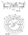
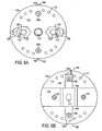
- FIG. 1A shows a portion of a food waste disposer 10 in side cross-section having the reduction mechanism 100
- Figure 1B shows the reduction mechanism 100 in a top view.
- the food waste disposer 10 has a food conveying section 12, a grinding section 14, and a motor section 16.
- the food conveying section 12 and part of the grinding section 14 are formed with a first housing portion 20, while another part of the grinding section and the motor section 16 are formed with a second housing 30.
- a coupling 22 between the first and second housings 20 and 30 includes flanges connected with fasteners and sealant, such as disclosed in the incorporated U.S. Patents Nos. 6,007,006 and 6,439,487 .
- the food conveying section 12 receives food waste (not shown) from a sink (not shown) and conveys the food waste to the grinding section 14.
- the disclosed reduction mechanism 100 is positioned in the grinding section 14 and includes a rotatable member or plate 110, one or more impact members or lugs 120, a first stationary member or plate 130, and a second stationary member or ring 140.
- a shaft 40 of a motor passes through an upper end bell 32 of the housing 30 and connects to the rotatable plate 110.
- a bearing/seal mechanism 42 and a mounting fastener 44 are used at the connection of the rotatable plate 110 and the shaft 40. Teachings of a bearing/seal mechanism, a mounting fastener, and associated techniques are disclosed in the 6,007,006 and 6,439,487 patents.
- the one or more impact members or lugs 120 are attached to the plate 110.
- two lugs 120 are used.
- the lugs 120 are attached to a peripheral portion of the rotatable plate 110.
- the lugs 120 are movably attached to the rotatable plate 110.
- Fastening posts 122 have one end attached in holes (not shown) in the rotatable plate 110. Other ends of the fastening posts 122 are attached in elongated throughholes in the lugs 120 that allow the lugs 120 to swivel and to slide relative to the rotatable plate 110.
- the lugs 120 have weighted ends 126 on an opposite end of the lugs from the elongated throughholes 124.
- the stationary plate 130 is disposed adjacent the rotatable plate 110. As best shown in Figure 1A, the stationary plate 130 extends beyond an inner dimension of the stationary ring 140 so that an outside edge 138 of the stationary plate 130 is mounted adjacent the ring 140. In the present embodiment, the edge 138 of the stationary plate 130 and a bottom shoulder 148 of the ring 140 are held together by a compression fit formed by the coupling 22 between the outside housings 20 and 30. In alternative embodiments, fasteners, clamps, welding, or other techniques and methods known in the art can be used to fixedly mount the stationary plate 130 and ring 140 adjacent one another.
- the stationary plate 130 defines a central opening 132 in which the rotatable plate 110 is positioned.
- the stationary plate 130 and the rotatable plate 110 are preferably on substantially the same plane, which allows bottom surfaces of the lugs 120 to pass substantially unhindered adjacent or over the stationary plate 130 and rotatable plate 110 as the lugs 120 slide and swivel during operation.
- a plurality of apertures 134 is formed in the stationary plate 130.
- the apertures 134 are used in combination with the lugs 120 to produce shearing or cutting forces to reduce the food waste.
- the apertures 134 include a plurality of holes formed within the interior area of the stationary plate 130.
- the apertures 134 include a plurality of gaps 136 formed by a plurality of horizontal teeth along the edge of the central opening 132 where the rotatable plate 110 is positioned.
- the stationary ring 140 is disposed about the periphery of the stationary plate 130.
- the stationary ring 140 has an inner wall 142, an upper shoulder 146, and a bottom shoulder 148.
- the inner wall 142 is substantially vertical with respect to the horizontal. plane of the rotatable plate 110 and stationary plate 130.
- the upper shoulder 146 mounts adjacent the first housing portion 20, and the bottom shoulder 148 mounts adjacent the outside edge 138 of the stationary plate 130.
- the outside edge 138 of the stationary plate 130 mounts adjacent a shoulder 33 of the second housing portion 30 so that the stationary ring 140 and plate 130 are sandwiched between the housings 20 and 30 when the disposer 10 is manufactured.
- additional techniques known in the art can be used to fixedly mount the stationary ring 140 in the housing of the disposer.
- the stationary ring 140 is preferably composed of Ni-Hard. Preferably, portions of the inner wall 142 are substantially perpendicular to the stationary plate 130, but this is not strictly necessary.
- the inner wall 142 of the ring 140 defines lower teeth 143, a ridge 144, and breakers or diverters 145.
- the lower teeth 143 are positioned adjacent the stationary plate 130 and the location where the weighted ends 126 of the lugs 120 pass when the disposer is operated.
- the ridge 144 projects a short distance inward toward the center of the ring 140. Ends of the lugs 120 are capable of passing under the ridge 144 when the disposer is operated.
- the lower teeth 143 in the present embodiment are inwardly projecting splines but could have other shapes.
- the lower teeth 143 are used as a grinding surface for food waste impacted and moved thereon as the lugs 120 and rotatable plate 110 are rotated during operation.
- the breakers or diverters 145 are also inwardly projecting splines.
- Other techniques and methods can be used for the construction of the stationary ring 140. For example, details of stationary rings such as those disclosed in the incorporated U.S. Patent Nos. 6,007,006 and 6,439,487 can be used with the disclosed reduction mechanism 100.
- the disclosed reduction mechanism 100 addresses the problem of sufficiently reducing fibrous or stringy food waste.
- the mere impact of the lugs 120 on food waste can reduce friable materials.
- the weighted ends 126 of the lugs 120 pass by the inner wall 142 of the ring 140 and create grinding forces on the food waste, which can also reduce such friable materials.
- the lugs 120 pass over the stationary plate 130 as the rotatable plate 110 is rotated.
- the passing of the lugs 120 over the apertures 134 in the stationary plate 130 creates shearing or cutting forces, which can reduce the size of fibrous or stringy materials. Therefore, the disclosed reduction mechanism 100 reduces food waste in two ways by both grinding and shearing to reduce the size of the food waste.
- the combined action between the ends 126 of the lugs 120 and the inner wall 142 and teeth 143 of the ring 140 act as a grinding or shredding mechanism, while the combined action between the edges or side surfaces of the lugs 120 with the apertures 134 and gaps 136 act as a shearing or cutting mechanism.
- friable food waste can be reduced to smaller particles by the mere impacts with the rotatable plate 110, lugs 120, and inner wall 142.
- the food waste is also reduced to smaller particles by the grinding forces or frictional interaction between the ends 126 of the lugs 120 and the inner wall 142 with teeth 143 of the ring 140.
- the food waste is reduced to smaller particles by the shearing or cutting forces produced by the interaction between the lugs 120 and a substantial number of the apertures 134 in the stationary plate 130. Such shearing or cutting forces can be beneficial in sufficiently reducing fibrous or stringy food waste.
- the lugs 120 of the disclosed reduction mechanism 100 have bottom surfaces or edges capable of passing over the stationary plate 130 in close proximity thereto in what is referred to as a shearing operation as the rotatable plate 110 rotates. Shearing thus refers to the ability of the bottom surfaces, edges, or blades of the lugs 120 to have contact with or near contact with the surfaces of the stationary plate 130 to allow the food to be sheared (i.e., cut) therebetween. In this regard, the lugs 120 would not shear if they passed over the stationary plate 130 at a significant separation distance.
- the separation distance permitting shearing action can depend on the size of the apertures 134, the resilience of the food waste, the mass of the lugs 120, and/or the speed of rotation of the plate 110, etc.
- a separation distance for shearing fibrous or stringy food waste. would generally would be in the range of 0-2 mm.
- the bottom surfaces, edges or blades of the lugs 120 pass over the entire area of the apertures 134 so that food waste passing through the apertures 134 cannot avoid being sheared at the apertures 134 by the lug 120.
- the lugs typically used in disposers are formed from bent pieces of sheet metal and, therefore, usually have rounded edges.
- the lugs 120 used in the disclosed reduction mechanism 100 are forged, cast, or machined and have substantially sharp edges formed with substantially flat bottom surfaces.
- the lugs 120 are capable or swiveling and sliding relative to the rotatable plate 110 and pass or travel over most if not all the apertures 134 in the stationary plate 130.
- the substantially sharp edges can enhance the shearing or cutting action that the lugs 120 produce when passing over the apertures 134 and gaps 136 in the stationary plate 110.
- the sharp edges can be formed by the bottom surface and a substantially perpendicular or acute sidewall.
- the lugs 120 are preferably forged or cast so that they can have an increased weight that is preferred for the disclosed reduction mechanism 100.
- the apertures 134 in the stationary plate 130 control the size of discharged particulate matter during the reduction operation. Because a radial gap does not exist between the stationary ring 140 and the rotatable plate 110 as seen in the prior art disposers (although such a radial gap could be provided), all the particulate matter produced in the grinding section 14 is discharged through the apertures 134 in the stationary plate 130. The size, number, and arrangement of these apertures 134 can be adjusted to obtain a desired amount of fineness of the particulate matter and an acceptable time for the reduction operation.
- the apertures 134 can be substantially round but can otherwise have any desirable shape.
- apertures (not shown) can be provided in the rotatable plate 110.
- the apertures 134 have a cross dimension or diameter of approximately from 3/16-inch and are arranged in a substantially uniform fashion where the lugs 120 may pass.
- the percentage of open area through the stationary plate 130 due to the size and number of apertures 134 is approximately 33 percent of the total surface area of the stationary plate 130. This percentage of open area has been found to be particularly suited for sufficiently reducing food waste, including fibrous and stringy waste, typically encountered by a food waste disposer. In general, however, consideration should be paid to a number of variables to achieve a suitable fineness of the particulate matter and an acceptable time for the reduction operation for a particular implementation of the reduction mechanism 100.
- Too much open area in the stationary plate 130 can allow undesirably large particulate matter to pass therethrough without being adequately reduced.
- too much open area can allow too much water to pass therethrough, causing food waste to collect inside the food conveying section 12 without being flushed to the discharge. Too little open area can prolong the reduction operation and can cause water to "back-up" in the food conveying section 12, which is generally not desirable.
- the lugs 120 may be fixedly attached to the rotatable plate 110.
- the rotating plate 110 in Figures 2A-2B has fixed lugs 121.
- Figure 2A shows the reduction mechanism 100 in side cross-section
- Figure 2B shows the reduction mechanism 100 in a top view.
- the fixed lugs 121 are attached to the peripheral portion of the plate 110 so that ends of the lugs 121 extend beyond the outside edge 118 of the plate 110.
- the ends of the fixed lugs 121 can, therefore, pass over the stationary plate 130 with apertures 134 to perform the shearing action of the disclosed reduction mechanism 100.
- the plate 110 may also include secondary lugs 128. Details related to preferred dimensions and placement of the fixed lugs 121 and secondary lugs 128 can be found in the incorporated U.S. Patent No. 6,439,487 .
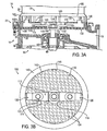
- FIG. 3A a portion of a food waste disposer 10 is illustrated in cross section having the disclosed reduction mechanism 100.
- the disclosed reduction mechanism 100 is shown in a top view.
- the disclosed reduction mechanism 100 is positioned in the grinding section 14 and includes a rotatable member or impeller 110, one or more impact members or lugs 120, a first stationary member or plate 130, and a second stationary member or ring 140.
- the rotatable impeller 110 is connected to the shaft 40 of the motor.
- the one or more lugs 120 are attached to the rotatable impeller 110.
- the stationary plate 130 is disposed adjacent the rotatable impeller 110, and the stationary ring 140 is disposed about the periphery of the stationary plate 130.
- the rotatable impeller 110 has a central portion 116 and one or more wing portions 114.
- the central portion 116 is mounted to the shaft 40 by a mounting fastener 44 known in the art.
- the rotatable impeller 110 includes two wing portions 114 as shown, and one lug 120 is preferably attached to each wing portion 114.
- the lugs 120 are movably attached to the wing portions 114.
- Fastening posts 122 have one end attached in holes (not visible) in the wing portions 114 and have other ends attached in throughholes (not visible) in the lugs 120 that allow the lugs 120 to swivel relative to the rotatable impeller 110.
- the lugs 120 have bottom surfaces adjacent the stationary plate 130 and have weighted ends 126 on an opposite end of the lugs 120 from the posts 122.
- the lugs 120 preferably have sharp edges formed with the substantially flat bottom surfaces. For example, the edges can be formed by the bottom edge and a substantially acute or perpendicular sidewall as shown and as discussed earlier. In alternative embodiments, the lugs 120 may be fixedly attached to the wing portions 114.
- the stationary plate 130 defines a central opening 132 in which the central portion 116 of the rotatable impeller 110 is positioned.
- the stationary plate 130 defines a plurality of apertures 134 therethrough that are distributed from the inner wall 142 of the ring 140 to the central opening 132 of the plate 130.
- the apertures 134 in the stationary plate 130 control the size of discharged particulate matter, and the size, number, and arrangement of these apertures 134 can be adjusted to obtain a desired amount of fineness of the particulate matter and an acceptable time for the reduction operation.
- the apertures 134 can be substantially round but can otherwise have any desirable shape.
- the apertures 134 have a cross dimension or diameter of approximately 3/16-inch and are arranged in a substantially uniform fashion.
- the percentage of open area through the stationary plate 130 due to the size and number of apertures 134 is approximately 33 percent of the total surface area of the stationary plate 130.
- the impeller 110 can be formed from a stock of sheet metal having a suitable thickness and can be bent into the wing shape as shown in Figures 3A-3B .
- the U-shaped central portion 116 for attaching the impeller 110 to the motor shaft 40 with the fastener 44 may require a larger central opening 132 in the stationary plate 130 than desired.
- a sealing mechanism can be used at this juncture.
- a cap member (not shown) can attach to the impeller's central portion 116 and substantially cover the central opening 132 in the stationary plate 130.
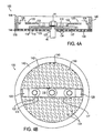
- FIG. 4A-4B An alternative embodiment of the reduction mechanism 100 is illustrated in the side cross-sectional view and the top view of Figures 4A-4B , respectively.
- the embodiment of the reduction mechanism 100 in Figure 4A-4B is substantially similar to that disclosed with reference to Figures 3A-3B .
- the impeller 110 can be a substantially flat bar of material as shown in Figures 4A-4B .
- a flat, central portion of the impeller 110 can attach to the shaft 40 so that the central opening 132 in the stationary plate 130 does not need to be much larger than the dimension of the shaft 40.
- the wing portions 114 and not just the lugs 120 can also produce shearing or cutting forces by passing over the apertures 134 in the plate 130 to reduce the food waste.
- the bottom of the impeller 110 can define a recess 115 (shown in Figure 4A , for example) for hiding the end 123 of the pin 122 that holds the lug 120 to the wing portion 114. In this way, the wing portion 114 can be positioned substantially close to the plate 130 for producing the shearing forces.
- the wing portions 114 can have acute (i.e., bladed) or perpendicular edges or sides 117 to pass substantially adjacent the surface of the plate 130 and create cutting action with the apertures 134.
- the impeller 110 may be forged, cast, or machined to have a preferred thickness, weight, and/or cutting edges 117.
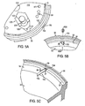
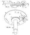
- FIGs 5A-5C portions of another embodiment of a food waste reduction mechanism are illustrated in various views. For clarity, not all of the components of the reduction mechanism and disposer are shown or discussed, particularly those that have been discussed earlier or that are well known in the art.
- the disposer is only partially shown having the upper housing removed.
- a rotatable plate 100 is shown positioned within an upper end bell 30 of the disposer's housing.
- the reduction mechanism includes a rotatable plate 110, impact members or lugs 120, and a stationary ring (not shown).
- the lugs 120 can include a toe 127 on the weighted end 126 that extends to the outside edge 118 of the plate 110.
- the stationary ring (not shown) positions against the rim 33 of the upper end bell 30, and the lugs 120 on the rotatable plate 110 are moved relative to the inside surface of the stationary ring (not shown) to shear and grind the food waste.
- the reduced food waste then falls through the gap G formed between the outside edge 118 of the plate 110 and the inner wall of the upper end bell 30. Because the stationary ring is not shown in Figure 5A , the gap G around the outside edge 118 of the plate 110 is shown larger than may actually be used in a particular implementation.
- the reduction mechanism of the present embodiment also includes a plurality of stationary cutting elements 150 used in conjunction with the rotatable plate 110, lugs 120, and stationary ring (not shown).
- the stationary cutting elements 150 are disposed about the upper end bell 30 of the disposer for shearing or cutting any fibrous or stringy materials that are discharged in the outer gap G between the stationary ring (not shown) and the edge 118 of the rotatable plate 110.
- the stationary cutting elements 150 include a sharp end or blade 152 and a mounting end 154.
- the stationary cutting elements 150 are mounted in a sidewall 34 of the upper end bell 30 so that the blades 152 project substantially horizontally below the bottom surface of the rotatable plate (not shown).
- a number of techniques known in the art can be used to mount the elements 150 to the upper end bell 30.
- the blades 152 can be disposed in slots 36 in the sidewall 34, and a fastener mechanism (not shown) can be used to fasten the mounting end 154 to the outside wall of the upper end bell 30.
- a conventional sealant (not shown) can be used to seal the slot 36 to prevent leakage.
- the cutting elements 150 are preferably positioned in a recess 37 formed within the sidewall 34 of the upper end bell 30.
- the upper end bell 30 is typically cast or molded and can be metal or plastic. Consequently, the recess 37 for the cutting element can be cast, molded, or machined into the upper end bell 30.
- a shoulder 38 can be provided to stabilize the cutting element 150, and a pin or other retainer 39 can hold the attachment end 154 of the cutting element 150 in the recess 37.
- the rotatable plate 110, lugs 120, and stationary ring reduce the food waste in a conventional manner.
- the reduced food waste is then allowed to pass through the gap G formed between the outside edge 118 of the plate 110 and the inner wall of the stationary ring (not shown).
- fibrous or stringy food waste may be able to fit between the gap G of the rotatable plate 110 and the stationary ring (not shown) without being sufficiently reduced to a desirable size.
- the plurality of cutting elements 150 mounted in the upper end bell 30 can cut any fibrous or stringy material that is discharged through the gap G.
- the food waste is being impacted, moved, and rotated so that any fibrous or stringy food waste fitting in the gap G will be cut or sheared by the stationary cutting elements 150.
- the plate 110 rotates, food waste moved by the plate 110 is tangentially flung at the stationary blades 152, thereby cutting the food waste.
- the toes 127 of the lugs 120 can be extended at least partially over the gap G, to improve the ability of the lugs 120 to impact food waste into the gap G and to assist in shearing the food waste.
- FIGS. 6A-6B portions of another embodiment of a food waste reduction mechanism are shown in a number of isolated views, in which Figures 6A and 6B respectively show the top and bottom of the reduction mechanism. Again, not all of the components of the reduction mechanism and disposer are shown for the sake of clarity.
- the reduction mechanism includes a rotatable plate 110, impact members or lugs 120, and a stationary ring (not shown).
- the reduction mechanism also includes one or more cutting elements 160 mounted to the plate 110. Each cutting element 160 includes a blade 162, a housing 164, and a mounting mechanism 166.
- the plate 110 has two or more such cutting elements 160 mounted on the bottom of the rotatable plate 110 to cut any fibrous material that is discharged through a gap between the stationary ring (not shown) and the outside edge of the rotatable plate as discussed earlier.
- the blades 162 and housings 164 are mounted to the bottom surface of the plate 110 using a mounting mechanism 166, such as a rivet.
- a number of other techniques known in the art can also be used to mount the housings 164 and blades 162 to the bottom of the rotatable plate 110.
- the housings 164 for each blade 162 can be separate components individually mounted to the plate 110.
- the housings 164 can be integral with one another so that a central portion passes between the rotatable plate 110 and a support member 116.
- the support member 116 is mounted to the bottom of the plate 110 and mounts to the motor shaft (not shown). Teachings of such a support member 116 are disclosed in the incorporated 6,007,006 and 6,439,487 patents.
- the housings 164 provide structural support for the blades 162. Depending on the mounting mechanism 166 used to attach the blades 162 to the plate 110, however, such structural housings 164 may not even be required.
- the blades 162 are free to rotate relative to the plate 110. During operation, centrifugal force keep the ends of the blades 162 beyond the edge 118 of the rotatable plate 110 for shearing or cutting any fibrous or stringy food waste escaping through the gap around the edge 118.
- the blades 162 can be fixedly mounted to the plate 110 so that the ends always extend beyond the edge 118 of the plate 110.
- FIGS. 7A-7B portions of another embodiment of a reduction mechanism are illustrated in relevant part in a number of isolated views, in which Figures 7A and 7B respectively illustrate a side view and a bottom perspective view.
- the reduction mechanism includes a rotatable plate 110, impact members or lugs 120, and a stationary ring (not shown).
- the impact members 120 are fixed to the rotatable plate 110 and include fixed lugs 121 and secondary lugs 128, having a design and location as disclosed in the incorporated 6,439,487 patent.
- the fixed lugs 121 and secondary lugs 128 are attached to the top surface of the plate 110, which is formed from a substantially thick piece of stock metal.
- the reduction mechanism also includes one or more planetary under-cutting elements, only one of which is shown in Figures 7A-7B .
- the planetary under-cutting element includes a rotatable hub 180 mounted to the plate 110 by a pin or shaft 186. As best shown in Figure 7B , the shaft 186 is mounted in a hole 188 in the plate 110 using a fastening mechanism known in the art.
- the planetary under-cutting element also includes one or more blades 184 disposed about the hub 180.
- the reduction mechanism also includes a stationary hub 190 mounted about the motor shaft 40 and having an internal bore for the passage of the shaft 40.
- the stationary hub 190 can be a separate component affixed to the upper end bell (not shown) of the disposer adjacent the location of the bearing/sealing mechanism, such as described above.
- a first portion 191 of the hub 190 may be an integral component of the upper end bell of the disposer, while a second portion 192 may be a separate component attaching to the first portion 191.
- the second portion 192 of the stationary hub 190 can be integrally formed on the first portion 191 attached to the upper end bell in this location of the disposer.
- a drive member such as a belt, chain, or the like, connects the stationary hub 190 to the rotating hub 180.
- a drive belt 196 is used.
- the second portion 192 of the stationary hub 190 and the rotating hub 180 preferably include peripheral tracks for the drive belt 196.
- the hubs 180 and 190 can have interconnecting gears (not shown) using techniques known in the art.
- the drive belt 196 in the present embodiment is shown positioned between the blades 184 and the surface of the plate 110.
- the drive belt 196 can connect to the hub 180 such that the blades 184 can be positioned between the drive belt 196 and the surface of the plate 110, which can allow the blades 184 to pass closer to the surface of the plate 110.
- the stationary hub 190 does not rotate with the motor shaft 40.
- the rotatable hub 180 of the under-cutter is free to rotate.
- the drive belt 192 connected between the hubs 180 and 190 causes the rotatable hub 180 to rotate in the opposite direction.
- the rotatable hub 180 can be made to rotate at a faster r.p.m. than the rotatable plate 110 because of the size ratio of peripheral tracks or ratio of gears, for example.
- the blades 184 pass over holes 111 in the plate 110 to cut food waste passing therethrough.
- ends of the one or more blades 184 on the rotatable hub 180 extend beyond the edge 118 of the rotatable plate 110. The ends of the blades 184 pass by the gap (not shown) formed between the edge 118 and stationary ring (not shown) to cut food waste passing through the gap.
- the blades 184 pass a distance H from the bottom surface of the plate 110, as shown in Figure 7B . Selection of the distance H may vary according to a particular implementation. To have a decreased distance H, it may be necessary for blades 184 to be positioned between the surface of the plate 110 and the location where the drive belt 192 connects to the hub 180. Washers, bearings, or other like devices can be used to facilitate rotation of the hub 180 relative to the plate 110. For embodiments of the disclosed reduction mechanism having more than one rotatable hub 180, the distances H that the blades 184 pass relative to the plate 110 may be different for the individual hubs 180.
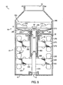
- FIGS. 8 , 9 , 10A-10C , and 11 portions of another embodiment of a reduction mechanism 200 for a food waste disposer 10 are illustrated in a number of views.
- the disposer 10 is schematically illustrated having the disclosed reduction mechanism. Again, not all of the components of the reduction mechanism 200 and disposer 10 are shown for clarity.
- the reduction mechanism 200 includes counter-rotating elements.
- the first element 201 is a grinding mechanism having a rotatable plate 210 and a primary rotational source or motor 230 having a stator 232 and a rotor 220.
- the second element 205 is a cutting mechanism having a cutting member 250 and a secondary rotational source or motor 270 having a stator 272 and a rotor 260.
- the primary rotor 220 rotates opposite from the secondary rotor 260 so that the rotatable plate 210 rotates opposite from the cutting member 250.
- the stators 232 and 272 have windings 236 and 276 that are wired to have opposite polarity with each other, so each one of its corresponding rotors 220 and 260 turns in the opposite direction.
- the primary motor 230 positions adjacent a lower end frame or bottom portion 17 of the motor housing 16.
- the primary motor 230 comprises an induction motor known in the art, but the primary motor 230 can comprise other dynamo-electric machines known in the art, such as a universal motor or a permanent magnet motor.
- the motor 230 includes a primary stator 232 and a primary rotor 220.
- the primary stator 232 is mounted in the housing 16.
- the primary stator 232 includes a plurality of laminations defining a plurality of poles with windings 236 wound thereon. It is understood that a number of other motors designs can be used with the disclosed reduction mechanism.
- an embodiment of a primary rotor 220 has a shaft 222 and includes a plurality of laminations 226 mounted on the primary rotor shaft 222 using techniques known in the art.
- An attachment end 224 of the shaft 222 attaches to the rotatable plate (210) using techniques known in the art.
- the other end of the shaft 222 rests on a stabilizing bearing assembly (not shown) on the lower end frame 17 of the motor housing 16, such as is known in the art.
- the secondary motor 270 positions adjacent the top of the motor housing 16.
- the secondary motor 270 can comprise an induction motor, a universal motor, a permanent magnet motor, or other dynamo-electric machine known in the art.
- the secondary stator 272 is mounted in the housing 16.
- the secondary stator 272 includes a plurality of laminations defining a plurality of poles 274 with windings 276 wound thereon. It is understood that a number of other motors designs can be used with the disclosed reduction mechanism.
- an embodiment of a secondary rotor 260 includes a shaft 262 having a plurality of rotor laminations 266 mounted thereon using techniques known in the art.
- the shaft 262 defines a hollow cylinder for disposing about the primary shaft 222, as best shown in Figures 10B-10C .
- One end of the hollow shaft 262 is attached to the cutting member 250, which is positioned under the rotatable plate when the disposer 10 is assembled as shown in Figure 11 .
- the hollow shaft 262 slides over the main rotor shaft 222 of the primary rotor 220.
- the cutting member 250 includes central portion 252 with one or more cutting blades 256 disposed thereabout.
- the central portion 252 can be dish-shaped so as not to interfere with a support member of the rotatable member 110.
- a central opening 254 in the cutting member 250 attaches to an end 264 of the hollow shaft 262 using techniques known in the art so that the cutting member 250 is rotatable with the shaft 262. For example, a boss and flange can be used or the components can be welded together.
- the rotatable plate 210 includes a support plate 216 attached to an end of the primary shaft by techniques common in the art.
- the rotatable plate 210 also includes swivel lugs 218 and fixed lugs 219, which are similar to those described earlier.
- the plate 210 and lugs 218 and 219 work in conjunction with a stationary ring 240 schematically shown in Figure 8 to reduce food waste.
- the secondary motor 270 is smaller than the primary motor 230 because most of the reduction work of the food waste has already been performed by the rotatable plate 210, lugs 218 and 219, and stationary ring 240.
- the primary motor 230 can produce between 1/2 to 1-horsepower.
- the secondary motor 270 can be approximately 1/3 to 1/5 the size of the primary motor 230. In one embodiment, therefore, the secondary motor 270 may produce about 1/8-horsepower. Accordingly, the secondary motor 270 can be and preferably is smaller than illustrated in the Figures.
- a number of sealing and bearing mechanisms can be used for the rotors 220 and 260.
- a bearing/sealing mechanism 42 known in the art is preferably used where the hollow shaft 262 passes through the upper end bell or portion 32 of the motor housing 16.
- another bearing mechanism 43 known in the art is provided in the lower end frame or portion 17 of the disposer 10.
- the upper end of the shaft 262 can include an internal bearing and sealing mechanism 280.
- the lower end 268 of the shaft 262 can also include an internal bearing mechanism 282 disposed about the primary shaft 222 and/or disposed on the laminations 226 of the primary rotor 220, for example.
- the internal bearing mechanisms 280 and 282 can be used to stabilize and improve rotation of the shafts 222 and 262 relative to one another.
- the disclosed reduction mechanism includes a rotatable plate 110 having both fixed and movable impact members 120.
- the impact members 120 on the plate 110 include movable lugs 320 and fixed lugs 330.
- the movable lugs 320 can include a toe 327 on a weighted end 326 that extends to an outside edge 118 of the plate 110.
- Elongated apertures 324 in the lugs 320 allow the lugs 320 to rotate and slide relative to a pin 322 attaching the lug 320 to the plate 110.
- the fixed lugs include primary lugs 330 positioned near the edge 118 of the plate 110.
- Secondary lugs 335 can be positioned within the interior of the plate 110. Teachings of preferred dimensions and locations of such fixed lugs 330 and 335 are disclosed in the incorporated 6,439,487 patents. Various embodiments of reduction mechanisms in the present disclosure can incorporate the present embodiment of the rotatable plate 110 of Figure 12 .
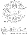
- Figures 13 and 14A-14D relevant parts of another embodiment of a reduction mechanism are illustrated in various views, in which Figure 13 shows a top view of a rotatable plate 110 having various impact members and Figures 14A-14D shows side views of these impact members.
- Figure 13 shows a top view of a rotatable plate 110 having various impact members
- Figures 14A-14D shows side views of these impact members.
- the actual size reduction or grinding of the food particles in typical food waste disposers is done by the interaction of the features on the rotating shredder plate with the stationary grind ring.
- swivel lugs are used in these grind mechanisms to throw the food against the stationary ring and reduce the size by breaking of the material with impact forces.
- the rotatable plate 110 has a plurality of impact members, including movable lugs 320, fixed lugs 330 and 335, and a rotating lug 340.
- the movable lugs 320 can be of conventional design and can include a toe 327 on a weighted end 326 that extends to an outside edge 118 of the plate 110.
- the movable lugs 320 break down friable foods through impact against a stationary ring (not shown).
- Elongated apertures 324 in the lugs 320 allow the lugs 320 to rotate and slide relative to a pin 322 attaching the lug 320 to the plate 110.
- the fixed lugs include primary lugs 330 positioned near the edge 118 of the plate 110. Secondary lugs 335 can be positioned within the interior of the plate 110. Teachings of preferred dimensions and locations of such fixed lugs 330 and 335 are disclosed in the incorporated 6,439,487 patent.
- the fixed lugs 330 and 335 are effective at tearing elastic foods waste, such as poultry skin.
- the fixed lugs 330 and 335 are effective at preventing fibrous food waste from "balling up" and are effective at increasing the overall fineness of the particulate matter produced by the reduction mechanism.
- the rotating lug 340 is designed to grab or snag fibrous food waste and pull it across breakers 348 to shear the fibrous food waste into shorter lengths.
- each of these impact members 320, 330, 335, and 340 has a different height so that it interacts with a different portion of the stationary ring (not shown) that is positioned about the edge 118 of the rotatable plate 110.
- the height differential also helps to break up bouncing harmonics of the food waste, thus reducing the potential for food waste to ride on the plate 110.
- the movable lug 320 as shown in Figure 14B is the tallest of the impact members and has a stepped face.
- the upper portion 327a of the face interacts with the upper breakers and diverters on the stationary ring.
- the lower portion or toe 327b interacts with the lower teeth of the stationary ring and does finish grinding of the food waste.
- the fixed lugs 330 and 335 as shown in Figures 14C-14D are slightly shorter than the swivel lugs 320 and have a narrow face width. Because the primary lugs 330 adjacent edge 118 are fixed and cannot move away from the stationary ring, they hold material against the stationary ring, which results in an overall finer grind than the use of swivel lugs alone.
- the rotating lug 340 is very close to the surface of the plate 110 so that it can grab and shear longer pieces of food waste that may accumulate at the base of the stationary ring near the edge 118 of the plate 110.
- the rotating lug 340 is balanced to rotate on a central shaft 342 that attaches to the plate 110 by a boss or retainer 343.
- the rotating lug 340 has a plurality of hooked teeth 344 for grabbing food waste accumulated at the base of the stationary ring.
- the rotating lug 340 has a plurality of pitched fins 346, which can facilitate its rotation. Breakers 348 are attached to the plate 110 on either side of the rotating lug 340 and interact with the hooked teeth 344 to tear and shear food waste.
- the rotating lug 340 can be rotated by the mere flow of water F that occurs as the rotatable plate 110 is rotated in direction R.
- the boss 343 that is on the shaft 342 on the underside of the plate 110 can be coupled to a stationary hub on the disposer by a drive member, such as a belt, in a similar fashion to the embodiment of the disclosed reduction mechanism of Figures 7A-7B .
- the rotating lug 340 would rotate counter to the direction R of the plate 110 so that the configuration of the hooked teeth 344 would need to be oriented in the reverse. Because the rotating lug 340 is balanced to rotate on the plate 110, it can continuously rotate by virtue of the water flow or drive member.
- the rotating lug 340 can freely rotate when not substantially interfered so that the rotating lug 340 can be said to continuously rotates even if it impacts food waste now and again.
- the swivel lug 320 cannot be said to rotate continuously like the rotating lug 340.
- the swivel lug 320 does not continuously rotate as the rotating lug 340 because centrifugal forces cause the weighted end of the swivel lug 320 to orient toward the edge 118 of the plate 110.
- the rotatable plate 110 having the various lugs 320, 330, 335, and 340 is not symmetrical about its central portion 112 and may, therefore, not be balanced for rotation. To balance and evenly distribute the mass of the plate 110 with lugs 320, 330, 335, and 340, it may be necessary to attach or form mass balancing members on the plate 110. As described earlier, the rotatable plate 110 can have a support plate 116 attached to the bottom surface. For example, the support plate 116 is used to attach the rotatable plate 110 to a motor shaft (not shown) and to reinforce the plate 110 where the posts 322 of the moveable lugs 320 attach.
- a mass balancing member 117 is attached to the bottom of the plate 110 adjacent the support plate 116 and may be an extended or separate portion of the support plate 116.
- the mass-balancing member 117 is positioned opposite the location of the rotating lug 340 to balance and evenly distribute the mass of the plate 110 and lugs 320, 330, 335, and 340 for rotation.
- the term "plate” is not meant to necessarily refer to a unitary body, or a body that is flat.
- the term “ring” is not meant to strictly refer to a unitary body having a continuous annular shape, nor a body having constant inner and outer diameters; multiple components may be arranged in a ring shape, and accordingly may still together be considered to constitute a "ring.”
Description
- The present invention relates generally to a food waste disposer and more particularly to a mechanism for reducing food waste in a disposer.
- In designing a mechanism for reducing food waste in a food waste disposer, consideration must be paid to the speed with which a reduction operation is completed and the resulting size of particulate matter produced during the reduction operation. A manufacturer must also consider the demands that a wide variety of food waste with varying properties (i.e., soft, hard, fibrous, stringy, leafy, elastic, and resilient) may have on a reduction mechanism in the disposer. Due to healthier diets, for example, consumers tend to eat more fruits and vegetables, resulting in food waste having a soft, stringy, leafy, or resilient consistency. Additionally, the modem diet has increased in consumption of white meat. The waste from meat typically includes bone. Although the bones from white meat are typically not as durable or difficult to grind compared to bones from red meat, the bones from white meat tend to splinter. In addition, the waste from white meat typically includes skin, which is elastic and resilient.
- A number of mechanisms for reducing food waste in a food waste disposer are used in the art. One example of a mechanism of the prior art is used in the General Electric Model GFC 700Y Household Disposer manufactured by Watertown Industries. Other examples of mechanisms of the prior art are disclosed in
U.S. Patent Nos. 6,007,006 to Engel et al. and6,439,487 to Anderson et al. , which are owned by the assignee of record and are incorporated herein by reference in their entireties. In the prior art disposers of the '006 and '487 patents, a rotatable plate is connected to a motor and has lugs attached to the plate. A stationary ring is attached to the housing of the disposer and is positioned vertically about the periphery of the rotatable plate. During operation of the prior art mechanisms, food waste is delivered to the rotatable plate, and the lugs force the food waste against the stationary ring. Teeth on the stationary ring grind the food waste into particulate matter sufficiently small enough to pass from above the rotatable plate to below the plate via spaces between the teeth and the periphery of the rotatable plate. The particulate matter then passes to a discharge outlet of the disposer. - While mechanisms of the prior art disposer are satisfactory for reducing food waste in most applications, designers of food waste disposers continually strive to design and manufacture mechanisms capable of adequately reducing a number of types of food waste that may be encountered by the disposer. Current designs of reduction mechanisms in disposers may encounter some difficulty in sufficiently reducing fibrous, stringy, or elastic food waste, such as cornhusks, artichokes, parsley stems, poultry bones, and poultry skin, for example. Such food waste may pass though the radial spaces between the rotatable plate and stationary ring without being adequately reduced in size. Consequently, the passed fibrous or stringy food waste may create blockages in the disposer discharge or in the household plumbing.
- The present invention is directed to overcoming, or at least reducing the effects of, one or more of the problems set forth above.
- Various mechanisms for reducing food waste in a food waste disposer are disclosed. In each of the reduction mechanisms, structures are provided for shearing food waste as it passes through or past a rotating shredder plate of the disposer.
- In one embodiment of the disclosed reduction mechanism, a rotatable plate is coupled to a shaft of a motor housed in the disposer. A stationary plate is disposed adjacent the rotatable plate and defines a plurality of apertures therethrough. The stationary plate has a central opening. The rotatable plate is positioned for rotation within the central opening of the stationary plate. The rotatable plate has a central portion coupled to the motor shaft and has a peripheral portion disposed adjacent the central opening in the stationary plate. One or more lugs are attached to the peripheral portion of the rotatable plate and have a surface or edge for passing over the apertures in the stationary plate for shearing the food waste during operation. The lugs can be movably attached to the rotatable plate and capable of swiveling and sliding relative to the rotatable plate. Alternatively, the lugs can be fixedly attached to the rotatable plate. Moreover, a combination of fixed and movable lugs can be used on the rotatable plate. Interaction between the lugs and the apertures in the plate produce shearing or cutting forces for reducing the food waste. A stationary ring is disposed in the disposer and has an inner wall disposed about the stationary plate. The lugs attached to the rotatable plate can have ends for passing adjacent the inner wall. Interaction between the lugs and the stationary ring produce grinding or shredding forces for reducing the food waste.
- In another embodiment of the disclosed reduction mechanism, an impeller has a central portion coupled to a motor shaft and has a wing portion positioned adjacent a stationary plate. A lug is attached to the wing portion and has a surface or edge for passing over the apertures in the stationary plate. The lug can be movably or fixedly attached to the impeller and can slide over to the stationary plate. Interaction between the lug and the apertures in the plate produce shearing or cutting forces for reducing the food waste. A substantially straight portion of the wing portion can also pass over the apertures in the stationary plate for shearing the food waste. Interaction between an end of the lug and the stationary ring produce grinding or shredding forces for reducing the food waste.
- In another embodiment of the disclosed reduction mechanism, a stationary ring is disposed in a housing of the disposer between the inlet and the outlet of the disposer. A rotatable plate is coupled to a motor shaft and is positioned for rotation relative to the inner wall of the stationary ring. The plate has fixed and/or movable lugs for reducing food waste with the stationary ring. Interaction between ends of the lug and the stationary ring produce grinding or shredding forces for reducing the food waste. The rotatable plate has an edge forming a gap with the stationary ring for conveying reduced food waste to the outlet. One or more cutting elements are mounted in housing of the disposer adjacent a bottom surface of the plate. Blades of the cutting elements extend adjacent the gap for cutting food waste conveyed through the gap.
- In another embodiment of the disclosed reduction mechanism, a stationary ring is disposed in a housing of the disposer between the inlet and the outlet of the disposer. A rotatable plate is coupled to a motor shaft and is positioned for rotation relative to the inner wall of the stationary ring. The plate has fixed and/or movable lugs for reducing food waste with the stationary ring. Interaction between ends of the lug and the stationary ring produce grinding or shredding forces for reducing the food waste. The rotatable plate has an edge forming a gap with the stationary ring for conveying reduced food waste to the outlet. One or more cutting elements are mounted on a bottom surface of the rotatable plate. Blades of the cutting elements extend beyond the edge of the plate for reducing food waste conveyed through the gap.
- In another embodiment of the disclosed reduction mechanism, a stationary ring is disposed in a housing of the disposer between the inlet and the outlet of the disposer. A rotatable plate is coupled to a first shaft of a first motor and is positioned for rotation relative to the inner wall of the stationary ring. The plate has fixed and/or movable lugs for reducing food waste with the stationary ring. Interaction between ends of the lug and the stationary ring produce grinding or shredding forces for reducing the food waste. The rotatable plate has an edge forming a gap with the stationary ring for conveying reduced food waste to the outlet. A rotatable cutting member is disposed underneath the rotatable plate and is coupled to a hollow shaft of a second motor housed in the disposer. The hollow shaft is disposed over first shaft, and the motors are housed one above the other in the housing. The shafts rotate in opposite directions. Blades on the rotatable cutting member extend beyond the edge of the rotatable plate for reducing food waste conveyed through the gap between the rotatable plate and stationary ring.
- In another embodiment of the disclosed reduction mechanism, a stationary ring is disposed in a housing of the disposer between the inlet and the outlet of the disposer. A rotatable plate is coupled to a motor shaft and is positioned for rotation relative to the inner wall of the stationary ring. The plate has fixed and movable lugs for reducing food waste with the stationary ring. Interaction between ends of the lugs and the stationary ring produce grinding or shredding forces for reducing the food waste. The rotatable plate has an edge forming a gap with the stationary ring for conveying reduced food waste to the outlet. A rotatable impact member is attached to a top surface of the rotatable plate. A plurality of hooked teeth on the rotatable impact member pass by the inner wall of the stationary ring. The hooked teeth also pass by breakers fixedly attached to the rotatable plate. The rotatable impact member can have pitched surfaces for engaging water flow that causes the rotatable impact member to rotate. A drive belt can be disposed about a shaft of the rotatable impact member and disposed about a central hub in the disposer to cause the rotatable impact member to rotate.
- In another embodiment of the disclosed reduction mechanism, a stationary ring is disposed in the housing of a disposer and has an inner wall. A rotatable plate is coupled to a motor shaft and is positioned for rotation relative to the inner wall of the stationary ring. One or more fixed lugs are attached to the rotatable plate for grinding food waste in combination with the inner wall of the stationary ring, and one or more movable lugs are attached to the rotatable plate for grinding food waste in combination with the inner wall of the stationary ring.
- In another embodiment of the disclosed reduction mechanism, a rotatable plate is coupled to the shaft of the rotational source and is positioned for rotation in the housing. A first hub is mounted about the shaft. A second hub is rotatably mounted on the rotatable plate and has at least one cutting element attached thereto for reducing food waste. A drive member connects the first hub to the second hub for rotating the second hub during operation of the disposer.
- The foregoing summary is not intended to summarize each potential embodiment or every aspect of the inventive concepts disclosed herein.
-
US3211389 relates to a waste disposer to provide a rotor for a food waste grinder having a structure for holding the grinding lug rigidly in a grinding position during normal waste-grinding operation. - The present invention is set out in the independent claims, with some optional features set out in the claims dependent thereto.
- The foregoing summary, preferred embodiments, and other aspects of the inventive concepts will be best understood with reference to a detailed description of specific embodiments, which follows, when read in conjunction with the accompanying drawings, in which:
- FIGS. 1A-1B illustrate various views of an embodiment of a reduction mechanism for shearing and grinding food waste according to certain teachings of the present disclosure, the disclosed reduction mechanism having a stationary ring, stationary plate, rotating plate, and movable lugs.
-
FIGS. 2A-2B illustrate various views of another embodiment of a reduction mechanism for shearing and grinding food waste according to certain teachings of the present disclosure, the disclosed reduction mechanism having a stationary ring, stationary plate, rotating plate, and fixed lugs. -
FIGS. 3A-3B illustrate various views of an embodiment of a reduction mechanism for shearing and grinding food waste according to certain teachings of the present disclosure, the disclosed reduction mechanism having a stationary ring, stationary plate, a rotating impeller, and movable lugs. -
FIGS. 4A-4B illustrate various views of another embodiment of a reduction mechanism for shearing and grinding food waste according to certain teachings of the present disclosure, the disclosed reduction mechanism having a stationary ring, stationary plate, a rotating impeller, and movable lugs. -
FIGS. 5A-5C illustrate various views of an embodiment of a reduction mechanism for shearing and grinding food waste according to certain teachings of the present disclosure, the disclosed reduction mechanism having stationary cutting elements mounted on the disposer. -
Figures 6A-6B illustrate various views of an embodiment of a reduction mechanism for shearing and grinding food waste according to certain teachings of the present disclosure, the disclosed reduction mechanism having cutting elements mounted on a rotatable plate. -
Figures 7A-7B illustrate various views of an embodiment of a reduction mechanism for shearing and grinding food waste according to certain teachings of the present disclosure, the disclosed reduction mechanism having cutting elements on a rotatable hub attached to a rotatable plate. -
Figures 8 ,9 ,10A-10C , and11 illustrate various views of an embodiment of a reduction mechanism for shearing and grinding food waste according to certain teachings of the present disclosure, the disclosed reduction mechanism having counter rotating elements. -
Figure 12 illustrates a top view of an embodiment of a rotatable plate having both fixed and movable lugs. -
Figure 13 illustrates a top view of an embodiment of a rotatable plate having fixed, movable, and rotatable impact members. -
Figures 14A-14D illustrate side views of the impact members for the rotatable plate ofFigure 13 . - While the disclosed reduction mechanisms for a food waste disposer are susceptible to various modifications and alternative forms, specific embodiments thereof have been shown by way of example in the drawings and are herein described in detail. The figures and written description are not intended to limit the scope of the disclosed reduction mechanism in any manner. Rather, the figures and written description are provided to illustrate the disclosed reduction mechanism to a person skilled in the art by reference to particular embodiments of the invention, as required by 35 U.S.C. § 112.
- In the interest of clarity, not all features of actual implementations of a reduction mechanism for a food waste disposer are described in the disclosure that follows. It will of course be appreciated that in the development of any such actual implementation, as in any such project, numerous engineering and design decisions must be made to achieve the developers' specific goals, e.g., compliance with mechanical and business related constraints, which will vary from one implementation to another. While attention must necessarily be paid to proper engineering and design practices for the environment in question, it should be appreciated that the development of a reduction mechanism would nevertheless be a routine undertaking for those of skill in the art given the details provided by this disclosure.
- Referring to Figures 1A-1B, an embodiment of a
reduction mechanism 100 is illustrated. Figure 1A shows a portion of afood waste disposer 10 in side cross-section having thereduction mechanism 100, and Figure 1B shows thereduction mechanism 100 in a top view. In Figure 1A, thefood waste disposer 10 has afood conveying section 12, a grindingsection 14, and amotor section 16. In the present example, thefood conveying section 12 and part of the grindingsection 14 are formed with afirst housing portion 20, while another part of the grinding section and themotor section 16 are formed with asecond housing 30. Several techniques and methods exist in the art for constructing the housing of a food waste disposer, and the disclosedreduction mechanism 100 is not limited to only the construction illustrated herein. Other techniques and methods for constructing the housings of food waste disposers are disclosed in incorporatedU.S. Patent Nos. 6,007,006 and6,439,487 . Thehousing portions coupling 22 between the first andsecond housings U.S. Patents Nos. 6,007,006 and6,439,487 . - The
food conveying section 12 receives food waste (not shown) from a sink (not shown) and conveys the food waste to the grindingsection 14. The disclosedreduction mechanism 100 is positioned in the grindingsection 14 and includes a rotatable member orplate 110, one or more impact members or lugs 120, a first stationary member orplate 130, and a second stationary member orring 140. Ashaft 40 of a motor (not shown) passes through anupper end bell 32 of thehousing 30 and connects to therotatable plate 110. A bearing/seal mechanism 42 and a mountingfastener 44 are used at the connection of therotatable plate 110 and theshaft 40. Teachings of a bearing/seal mechanism, a mounting fastener, and associated techniques are disclosed in the 6,007,006 and 6,439,487 patents. - The one or more impact members or lugs 120 are attached to the
plate 110. Preferably, twolugs 120 are used. Thelugs 120 are attached to a peripheral portion of therotatable plate 110. In the present embodiment, thelugs 120 are movably attached to therotatable plate 110. Fasteningposts 122 have one end attached in holes (not shown) in therotatable plate 110. Other ends of the fastening posts 122 are attached in elongated throughholes in thelugs 120 that allow thelugs 120 to swivel and to slide relative to therotatable plate 110. Thelugs 120 have weighted ends 126 on an opposite end of the lugs from theelongated throughholes 124. - The
stationary plate 130 is disposed adjacent therotatable plate 110. As best shown in Figure 1A, thestationary plate 130 extends beyond an inner dimension of thestationary ring 140 so that anoutside edge 138 of thestationary plate 130 is mounted adjacent thering 140. In the present embodiment, theedge 138 of thestationary plate 130 and abottom shoulder 148 of thering 140 are held together by a compression fit formed by thecoupling 22 between theoutside housings stationary plate 130 andring 140 adjacent one another. Thestationary plate 130 defines acentral opening 132 in which therotatable plate 110 is positioned. Thestationary plate 130 and therotatable plate 110 are preferably on substantially the same plane, which allows bottom surfaces of thelugs 120 to pass substantially unhindered adjacent or over thestationary plate 130 androtatable plate 110 as thelugs 120 slide and swivel during operation. - A plurality of
apertures 134 is formed in thestationary plate 130. Theapertures 134 are used in combination with thelugs 120 to produce shearing or cutting forces to reduce the food waste. In the present embodiment of the disclosedstationary plate 130, theapertures 134 include a plurality of holes formed within the interior area of thestationary plate 130. In addition, theapertures 134 include a plurality ofgaps 136 formed by a plurality of horizontal teeth along the edge of thecentral opening 132 where therotatable plate 110 is positioned. - The
stationary ring 140 is disposed about the periphery of thestationary plate 130. Thestationary ring 140 has aninner wall 142, anupper shoulder 146, and abottom shoulder 148. Theinner wall 142 is substantially vertical with respect to the horizontal. plane of therotatable plate 110 andstationary plate 130. Theupper shoulder 146 mounts adjacent thefirst housing portion 20, and thebottom shoulder 148 mounts adjacent theoutside edge 138 of thestationary plate 130. Theoutside edge 138 of thestationary plate 130 mounts adjacent ashoulder 33 of thesecond housing portion 30 so that thestationary ring 140 andplate 130 are sandwiched between thehousings disposer 10 is manufactured. As noted above, additional techniques known in the art can be used to fixedly mount thestationary ring 140 in the housing of the disposer. - In the present embodiment of the
reduction mechanism 100, thestationary ring 140 is preferably composed of Ni-Hard. Preferably, portions of theinner wall 142 are substantially perpendicular to thestationary plate 130, but this is not strictly necessary. In addition, theinner wall 142 of thering 140 defineslower teeth 143, aridge 144, and breakers ordiverters 145. Thelower teeth 143 are positioned adjacent thestationary plate 130 and the location where the weighted ends 126 of thelugs 120 pass when the disposer is operated. Theridge 144 projects a short distance inward toward the center of thering 140. Ends of thelugs 120 are capable of passing under theridge 144 when the disposer is operated. Thelower teeth 143 in the present embodiment are inwardly projecting splines but could have other shapes. Thelower teeth 143 are used as a grinding surface for food waste impacted and moved thereon as thelugs 120 androtatable plate 110 are rotated during operation. The breakers ordiverters 145 are also inwardly projecting splines. Other techniques and methods can be used for the construction of thestationary ring 140. For example, details of stationary rings such as those disclosed in the incorporatedU.S. Patent Nos. 6,007,006 and6,439,487 can be used with the disclosedreduction mechanism 100. - The disclosed
reduction mechanism 100 addresses the problem of sufficiently reducing fibrous or stringy food waste. As theplate 110 is rotated, the mere impact of thelugs 120 on food waste can reduce friable materials. The weighted ends 126 of thelugs 120 pass by theinner wall 142 of thering 140 and create grinding forces on the food waste, which can also reduce such friable materials. Furthermore, thelugs 120 pass over thestationary plate 130 as therotatable plate 110 is rotated. The passing of thelugs 120 over theapertures 134 in thestationary plate 130 creates shearing or cutting forces, which can reduce the size of fibrous or stringy materials. Therefore, the disclosedreduction mechanism 100 reduces food waste in two ways by both grinding and shearing to reduce the size of the food waste. More specifically, the combined action between theends 126 of thelugs 120 and theinner wall 142 andteeth 143 of thering 140 act as a grinding or shredding mechanism, while the combined action between the edges or side surfaces of thelugs 120 with theapertures 134 andgaps 136 act as a shearing or cutting mechanism. - As a grinding mechanism, friable food waste can be reduced to smaller particles by the mere impacts with the
rotatable plate 110, lugs 120, andinner wall 142. The food waste is also reduced to smaller particles by the grinding forces or frictional interaction between theends 126 of thelugs 120 and theinner wall 142 withteeth 143 of thering 140. As a shearing mechanism, the food waste is reduced to smaller particles by the shearing or cutting forces produced by the interaction between thelugs 120 and a substantial number of theapertures 134 in thestationary plate 130. Such shearing or cutting forces can be beneficial in sufficiently reducing fibrous or stringy food waste. - As noted earlier, the
lugs 120 of the disclosedreduction mechanism 100 have bottom surfaces or edges capable of passing over thestationary plate 130 in close proximity thereto in what is referred to as a shearing operation as therotatable plate 110 rotates. Shearing thus refers to the ability of the bottom surfaces, edges, or blades of thelugs 120 to have contact with or near contact with the surfaces of thestationary plate 130 to allow the food to be sheared (i.e., cut) therebetween. In this regard, thelugs 120 would not shear if they passed over thestationary plate 130 at a significant separation distance. As one skilled in the art will recognize, the separation distance permitting shearing action can depend on the size of theapertures 134, the resilience of the food waste, the mass of thelugs 120, and/or the speed of rotation of theplate 110, etc. A separation distance for shearing fibrous or stringy food waste.would generally would be in the range of 0-2 mm. Furthermore, it is preferred that the bottom surfaces, edges or blades of thelugs 120 pass over the entire area of theapertures 134 so that food waste passing through theapertures 134 cannot avoid being sheared at theapertures 134 by thelug 120. - Some of the lugs typically used in disposers are formed from bent pieces of sheet metal and, therefore, usually have rounded edges. Preferably, the
lugs 120 used in the disclosedreduction mechanism 100 are forged, cast, or machined and have substantially sharp edges formed with substantially flat bottom surfaces. During operation, thelugs 120 are capable or swiveling and sliding relative to therotatable plate 110 and pass or travel over most if not all theapertures 134 in thestationary plate 130. The substantially sharp edges can enhance the shearing or cutting action that thelugs 120 produce when passing over theapertures 134 andgaps 136 in thestationary plate 110. The sharp edges can be formed by the bottom surface and a substantially perpendicular or acute sidewall. In addition, thelugs 120 are preferably forged or cast so that they can have an increased weight that is preferred for the disclosedreduction mechanism 100. - The
apertures 134 in thestationary plate 130 control the size of discharged particulate matter during the reduction operation. Because a radial gap does not exist between thestationary ring 140 and therotatable plate 110 as seen in the prior art disposers (although such a radial gap could be provided), all the particulate matter produced in the grindingsection 14 is discharged through theapertures 134 in thestationary plate 130. The size, number, and arrangement of theseapertures 134 can be adjusted to obtain a desired amount of fineness of the particulate matter and an acceptable time for the reduction operation. Theapertures 134 can be substantially round but can otherwise have any desirable shape. In addition, apertures (not shown) can be provided in therotatable plate 110. - Preferably, the
apertures 134 have a cross dimension or diameter of approximately from 3/16-inch and are arranged in a substantially uniform fashion where thelugs 120 may pass. Preferably, the percentage of open area through thestationary plate 130 due to the size and number ofapertures 134 is approximately 33 percent of the total surface area of thestationary plate 130. This percentage of open area has been found to be particularly suited for sufficiently reducing food waste, including fibrous and stringy waste, typically encountered by a food waste disposer. In general, however, consideration should be paid to a number of variables to achieve a suitable fineness of the particulate matter and an acceptable time for the reduction operation for a particular implementation of thereduction mechanism 100. Too much open area in thestationary plate 130, for example, can allow undesirably large particulate matter to pass therethrough without being adequately reduced. In addition, too much open area can allow too much water to pass therethrough, causing food waste to collect inside thefood conveying section 12 without being flushed to the discharge. Too little open area can prolong the reduction operation and can cause water to "back-up" in thefood conveying section 12, which is generally not desirable. - In alternative embodiments, the
lugs 120 may be fixedly attached to therotatable plate 110. For example, therotating plate 110 inFigures 2A-2B has fixedlugs 121.Figure 2A shows thereduction mechanism 100 in side cross-section, andFigure 2B shows thereduction mechanism 100 in a top view. The fixed lugs 121 are attached to the peripheral portion of theplate 110 so that ends of thelugs 121 extend beyond theoutside edge 118 of theplate 110. The ends of the fixedlugs 121 can, therefore, pass over thestationary plate 130 withapertures 134 to perform the shearing action of the disclosedreduction mechanism 100. Theplate 110 may also includesecondary lugs 128. Details related to preferred dimensions and placement of the fixedlugs 121 andsecondary lugs 128 can be found in the incorporatedU.S. Patent No. 6,439,487 . - Referring to
Figures 3A-3B , another embodiment of areduction mechanism 100 according to certain teachings of the present disclosure is illustrated. InFigure 3A , a portion of afood waste disposer 10 is illustrated in cross section having the disclosedreduction mechanism 100. InFigure 3B , the disclosedreduction mechanism 100 is shown in a top view. The disclosedreduction mechanism 100 is positioned in the grindingsection 14 and includes a rotatable member orimpeller 110, one or more impact members or lugs 120, a first stationary member orplate 130, and a second stationary member orring 140. - The
rotatable impeller 110 is connected to theshaft 40 of the motor. The one ormore lugs 120 are attached to therotatable impeller 110. Thestationary plate 130 is disposed adjacent therotatable impeller 110, and thestationary ring 140 is disposed about the periphery of thestationary plate 130. Therotatable impeller 110 has acentral portion 116 and one ormore wing portions 114. Thecentral portion 116 is mounted to theshaft 40 by a mountingfastener 44 known in the art. Preferably, therotatable impeller 110 includes twowing portions 114 as shown, and onelug 120 is preferably attached to eachwing portion 114. - In the present embodiment, the
lugs 120 are movably attached to thewing portions 114. Fasteningposts 122 have one end attached in holes (not visible) in thewing portions 114 and have other ends attached in throughholes (not visible) in thelugs 120 that allow thelugs 120 to swivel relative to therotatable impeller 110. Thelugs 120 have bottom surfaces adjacent thestationary plate 130 and have weighted ends 126 on an opposite end of thelugs 120 from theposts 122. Thelugs 120 preferably have sharp edges formed with the substantially flat bottom surfaces. For example, the edges can be formed by the bottom edge and a substantially acute or perpendicular sidewall as shown and as discussed earlier. In alternative embodiments, thelugs 120 may be fixedly attached to thewing portions 114. - Certain details of the
stationary plate 130 andring 140 are substantially similar to those described above. Thestationary plate 130 defines acentral opening 132 in which thecentral portion 116 of therotatable impeller 110 is positioned. Thestationary plate 130 defines a plurality ofapertures 134 therethrough that are distributed from theinner wall 142 of thering 140 to thecentral opening 132 of theplate 130. As noted above, theapertures 134 in thestationary plate 130 control the size of discharged particulate matter, and the size, number, and arrangement of theseapertures 134 can be adjusted to obtain a desired amount of fineness of the particulate matter and an acceptable time for the reduction operation. Theapertures 134 can be substantially round but can otherwise have any desirable shape. Preferably, theapertures 134 have a cross dimension or diameter of approximately 3/16-inch and are arranged in a substantially uniform fashion. Preferably, the percentage of open area through thestationary plate 130 due to the size and number ofapertures 134 is approximately 33 percent of the total surface area of thestationary plate 130. - The
impeller 110 can be formed from a stock of sheet metal having a suitable thickness and can be bent into the wing shape as shown inFigures 3A-3B . As best shown inFigure 3B , the U-shapedcentral portion 116 for attaching theimpeller 110 to themotor shaft 40 with thefastener 44 may require a largercentral opening 132 in thestationary plate 130 than desired. Accordingly, a sealing mechanism can be used at this juncture. For example, a cap member (not shown) can attach to the impeller'scentral portion 116 and substantially cover thecentral opening 132 in thestationary plate 130. - An alternative embodiment of the
reduction mechanism 100 is illustrated in the side cross-sectional view and the top view ofFigures 4A-4B , respectively. The embodiment of thereduction mechanism 100 inFigure 4A-4B is substantially similar to that disclosed with reference toFigures 3A-3B . However, theimpeller 110 can be a substantially flat bar of material as shown inFigures 4A-4B . A flat, central portion of theimpeller 110 can attach to theshaft 40 so that thecentral opening 132 in thestationary plate 130 does not need to be much larger than the dimension of theshaft 40. - In either of the embodiments disclosed in
Figures 3A-3B or4A-4B , thewing portions 114 and not just thelugs 120 can also produce shearing or cutting forces by passing over theapertures 134 in theplate 130 to reduce the food waste. Accordingly, the bottom of theimpeller 110 can define a recess 115 (shown inFigure 4A , for example) for hiding theend 123 of thepin 122 that holds thelug 120 to thewing portion 114. In this way, thewing portion 114 can be positioned substantially close to theplate 130 for producing the shearing forces. Furthermore, to enhance the shearing action, thewing portions 114 can have acute (i.e., bladed) or perpendicular edges orsides 117 to pass substantially adjacent the surface of theplate 130 and create cutting action with theapertures 134. In one embodiment, theimpeller 110 may be forged, cast, or machined to have a preferred thickness, weight, and/or cuttingedges 117. - Referring to
Figures 5A-5C , portions of another embodiment of a food waste reduction mechanism are illustrated in various views. For clarity, not all of the components of the reduction mechanism and disposer are shown or discussed, particularly those that have been discussed earlier or that are well known in the art. InFigure 5A , the disposer is only partially shown having the upper housing removed. In the top view ofFigure 5A , arotatable plate 100 is shown positioned within anupper end bell 30 of the disposer's housing. The reduction mechanism includes arotatable plate 110, impact members or lugs 120, and a stationary ring (not shown). As shown inFigure 5A , thelugs 120 can include atoe 127 on theweighted end 126 that extends to theoutside edge 118 of theplate 110. As disclosed above, the stationary ring (not shown) positions against therim 33 of theupper end bell 30, and thelugs 120 on therotatable plate 110 are moved relative to the inside surface of the stationary ring (not shown) to shear and grind the food waste. The reduced food waste then falls through the gap G formed between theoutside edge 118 of theplate 110 and the inner wall of theupper end bell 30. Because the stationary ring is not shown inFigure 5A , the gap G around theoutside edge 118 of theplate 110 is shown larger than may actually be used in a particular implementation. - The reduction mechanism of the present embodiment also includes a plurality of
stationary cutting elements 150 used in conjunction with therotatable plate 110, lugs 120, and stationary ring (not shown). Thestationary cutting elements 150 are disposed about theupper end bell 30 of the disposer for shearing or cutting any fibrous or stringy materials that are discharged in the outer gap G between the stationary ring (not shown) and theedge 118 of therotatable plate 110. - In the perspective views of
Figures 5B-5C , the disposer is again only partially shown, and therotatable plate 110 is shown removed to reveal portions of theupper end bell 30 and cuttingelements 150. Thestationary cutting elements 150 include a sharp end orblade 152 and a mountingend 154. Thestationary cutting elements 150 are mounted in asidewall 34 of theupper end bell 30 so that theblades 152 project substantially horizontally below the bottom surface of the rotatable plate (not shown). A number of techniques known in the art can be used to mount theelements 150 to theupper end bell 30. For example, theblades 152 can be disposed inslots 36 in thesidewall 34, and a fastener mechanism (not shown) can be used to fasten the mountingend 154 to the outside wall of theupper end bell 30. A conventional sealant (not shown) can be used to seal theslot 36 to prevent leakage. In a modification shown inFigure 5C , the cuttingelements 150 are preferably positioned in arecess 37 formed within thesidewall 34 of theupper end bell 30. Theupper end bell 30 is typically cast or molded and can be metal or plastic. Consequently, therecess 37 for the cutting element can be cast, molded, or machined into theupper end bell 30. Ashoulder 38 can be provided to stabilize thecutting element 150, and a pin orother retainer 39 can hold theattachment end 154 of the cuttingelement 150 in therecess 37. Thus, any potential for leakage in thesidewall 34 of the upper endupper end bell 30 of the disposer can be avoided. - During operation of the disposer, the
rotatable plate 110, lugs 120, and stationary ring (not shown) reduce the food waste in a conventional manner. The reduced food waste is then allowed to pass through the gap G formed between theoutside edge 118 of theplate 110 and the inner wall of the stationary ring (not shown). As noted above, fibrous or stringy food waste may be able to fit between the gap G of therotatable plate 110 and the stationary ring (not shown) without being sufficiently reduced to a desirable size. The plurality of cuttingelements 150 mounted in theupper end bell 30 can cut any fibrous or stringy material that is discharged through the gap G. During the reduction operation, the food waste is being impacted, moved, and rotated so that any fibrous or stringy food waste fitting in the gap G will be cut or sheared by thestationary cutting elements 150. Specifically, as theplate 110 rotates, food waste moved by theplate 110 is tangentially flung at thestationary blades 152, thereby cutting the food waste. If beneficial, thetoes 127 of thelugs 120 can be extended at least partially over the gap G, to improve the ability of thelugs 120 to impact food waste into the gap G and to assist in shearing the food waste. - Referring to
Figures 6A-6B , portions of another embodiment of a food waste reduction mechanism are shown in a number of isolated views, in whichFigures 6A and 6B respectively show the top and bottom of the reduction mechanism. Again, not all of the components of the reduction mechanism and disposer are shown for the sake of clarity. The reduction mechanism includes arotatable plate 110, impact members or lugs 120, and a stationary ring (not shown). The reduction mechanism also includes one ormore cutting elements 160 mounted to theplate 110. Each cuttingelement 160 includes ablade 162, ahousing 164, and amounting mechanism 166. Preferably, theplate 110 has two or moresuch cutting elements 160 mounted on the bottom of therotatable plate 110 to cut any fibrous material that is discharged through a gap between the stationary ring (not shown) and the outside edge of the rotatable plate as discussed earlier. Theblades 162 andhousings 164 are mounted to the bottom surface of theplate 110 using amounting mechanism 166, such as a rivet. A number of other techniques known in the art can also be used to mount thehousings 164 andblades 162 to the bottom of therotatable plate 110. - As best shown in bottom view of the
plate 110 inFigure 6B , thehousings 164 for eachblade 162 can be separate components individually mounted to theplate 110. Alternatively, thehousings 164 can be integral with one another so that a central portion passes between therotatable plate 110 and asupport member 116. Thesupport member 116 is mounted to the bottom of theplate 110 and mounts to the motor shaft (not shown). Teachings of such asupport member 116 are disclosed in the incorporated 6,007,006 and 6,439,487 patents. Thehousings 164 provide structural support for theblades 162. Depending on themounting mechanism 166 used to attach theblades 162 to theplate 110, however, suchstructural housings 164 may not even be required. In one embodiment, theblades 162 are free to rotate relative to theplate 110. During operation, centrifugal force keep the ends of theblades 162 beyond theedge 118 of therotatable plate 110 for shearing or cutting any fibrous or stringy food waste escaping through the gap around theedge 118. Alternatively, theblades 162 can be fixedly mounted to theplate 110 so that the ends always extend beyond theedge 118 of theplate 110. - Referring to
Figures 7A-7B , portions of another embodiment of a reduction mechanism are illustrated in relevant part in a number of isolated views, in whichFigures 7A and 7B respectively illustrate a side view and a bottom perspective view. The reduction mechanism includes arotatable plate 110, impact members or lugs 120, and a stationary ring (not shown). In the present embodiment, theimpact members 120 are fixed to therotatable plate 110 and include fixedlugs 121 andsecondary lugs 128, having a design and location as disclosed in the incorporated 6,439,487 patent. The fixed lugs 121 andsecondary lugs 128 are attached to the top surface of theplate 110, which is formed from a substantially thick piece of stock metal. - The reduction mechanism also includes one or more planetary under-cutting elements, only one of which is shown in
Figures 7A-7B . The planetary under-cutting element includes arotatable hub 180 mounted to theplate 110 by a pin orshaft 186. As best shown inFigure 7B , theshaft 186 is mounted in ahole 188 in theplate 110 using a fastening mechanism known in the art. The planetary under-cutting element also includes one ormore blades 184 disposed about thehub 180. - The reduction mechanism also includes a
stationary hub 190 mounted about themotor shaft 40 and having an internal bore for the passage of theshaft 40. Thestationary hub 190 can be a separate component affixed to the upper end bell (not shown) of the disposer adjacent the location of the bearing/sealing mechanism, such as described above. For example, a first portion 191 of thehub 190 may be an integral component of the upper end bell of the disposer, while asecond portion 192 may be a separate component attaching to the first portion 191. Alternatively, thesecond portion 192 of thestationary hub 190 can be integrally formed on the first portion 191 attached to the upper end bell in this location of the disposer. - A drive member, such as a belt, chain, or the like, connects the
stationary hub 190 to therotating hub 180. In the present embodiment, adrive belt 196 is used. Thus, thesecond portion 192 of thestationary hub 190 and therotating hub 180 preferably include peripheral tracks for thedrive belt 196. In alternative arrangements, thehubs drive belt 196 in the present embodiment is shown positioned between theblades 184 and the surface of theplate 110. Preferably, thedrive belt 196 can connect to thehub 180 such that theblades 184 can be positioned between thedrive belt 196 and the surface of theplate 110, which can allow theblades 184 to pass closer to the surface of theplate 110. - During operation, the
stationary hub 190 does not rotate with themotor shaft 40. Therotatable hub 180 of the under-cutter, however, is free to rotate. As theshredder plate 110 spins, thedrive belt 192 connected between thehubs rotatable hub 180 to rotate in the opposite direction. Therotatable hub 180 can be made to rotate at a faster r.p.m. than therotatable plate 110 because of the size ratio of peripheral tracks or ratio of gears, for example. To reduce food waste, theblades 184 pass overholes 111 in theplate 110 to cut food waste passing therethrough. In addition, ends of the one ormore blades 184 on therotatable hub 180 extend beyond theedge 118 of therotatable plate 110. The ends of theblades 184 pass by the gap (not shown) formed between theedge 118 and stationary ring (not shown) to cut food waste passing through the gap. - The
blades 184 pass a distance H from the bottom surface of theplate 110, as shown inFigure 7B . Selection of the distance H may vary according to a particular implementation. To have a decreased distance H, it may be necessary forblades 184 to be positioned between the surface of theplate 110 and the location where thedrive belt 192 connects to thehub 180. Washers, bearings, or other like devices can be used to facilitate rotation of thehub 180 relative to theplate 110. For embodiments of the disclosed reduction mechanism having more than onerotatable hub 180, the distances H that theblades 184 pass relative to theplate 110 may be different for theindividual hubs 180. - Referring to
Figures 8 ,9 ,10A-10C , and11 , portions of another embodiment of areduction mechanism 200 for afood waste disposer 10 are illustrated in a number of views. InFigure 8 , thedisposer 10 is schematically illustrated having the disclosed reduction mechanism. Again, not all of the components of thereduction mechanism 200 anddisposer 10 are shown for clarity. By way of introduction and before discussion of the aspects of the Figures, thereduction mechanism 200 includes counter-rotating elements. As best shown in thedisposer 10 schematically shown inFigure 8 , the first element 201 is a grinding mechanism having arotatable plate 210 and a primary rotational source ormotor 230 having astator 232 and arotor 220. The second element 205 is a cutting mechanism having a cuttingmember 250 and a secondary rotational source ormotor 270 having astator 272 and arotor 260. Theprimary rotor 220 rotates opposite from thesecondary rotor 260 so that therotatable plate 210 rotates opposite from the cuttingmember 250. Accordingly, thestators windings corresponding rotors - The
primary motor 230 positions adjacent a lower end frame orbottom portion 17 of themotor housing 16. Preferably, theprimary motor 230 comprises an induction motor known in the art, but theprimary motor 230 can comprise other dynamo-electric machines known in the art, such as a universal motor or a permanent magnet motor. Themotor 230 includes aprimary stator 232 and aprimary rotor 220. Theprimary stator 232 is mounted in thehousing 16. Theprimary stator 232 includes a plurality of laminations defining a plurality of poles withwindings 236 wound thereon. It is understood that a number of other motors designs can be used with the disclosed reduction mechanism. - As best shown in
Figure 9 , an embodiment of aprimary rotor 220 has ashaft 222 and includes a plurality oflaminations 226 mounted on theprimary rotor shaft 222 using techniques known in the art. Anattachment end 224 of theshaft 222 attaches to the rotatable plate (210) using techniques known in the art. The other end of theshaft 222 rests on a stabilizing bearing assembly (not shown) on thelower end frame 17 of themotor housing 16, such as is known in the art. - As best shown in
Figure 8 , thesecondary motor 270 positions adjacent the top of themotor housing 16. Thesecondary motor 270 can comprise an induction motor, a universal motor, a permanent magnet motor, or other dynamo-electric machine known in the art. Thesecondary stator 272 is mounted in thehousing 16. Thesecondary stator 272 includes a plurality of laminations defining a plurality of poles 274 withwindings 276 wound thereon. It is understood that a number of other motors designs can be used with the disclosed reduction mechanism. - As best shown in
Figures 10A-10C , an embodiment of asecondary rotor 260 includes ashaft 262 having a plurality ofrotor laminations 266 mounted thereon using techniques known in the art. Theshaft 262 defines a hollow cylinder for disposing about theprimary shaft 222, as best shown inFigures 10B-10C . One end of thehollow shaft 262 is attached to the cuttingmember 250, which is positioned under the rotatable plate when thedisposer 10 is assembled as shown inFigure 11 . When assembling thedisposer 10, thehollow shaft 262 slides over themain rotor shaft 222 of theprimary rotor 220. - As best shown in
Figures 10A and 10B , the cuttingmember 250 includescentral portion 252 with one ormore cutting blades 256 disposed thereabout. Thecentral portion 252 can be dish-shaped so as not to interfere with a support member of therotatable member 110. Acentral opening 254 in the cuttingmember 250 attaches to anend 264 of thehollow shaft 262 using techniques known in the art so that the cuttingmember 250 is rotatable with theshaft 262. For example, a boss and flange can be used or the components can be welded together. - Referring to
Figures 8 and11 , therotatable plate 210 includes asupport plate 216 attached to an end of the primary shaft by techniques common in the art. Therotatable plate 210 also includes swivel lugs 218 and fixedlugs 219, which are similar to those described earlier. Theplate 210 and lugs 218 and 219 work in conjunction with astationary ring 240 schematically shown inFigure 8 to reduce food waste. - Any material that is discharged through the gap G between the
stationary ring 240 and therotatable plate 210 is reduced by theblades 256 of cuttingmember 250 rotating in the other direction. For example, theblades 256 cut or shear fibrous or stringy materials before they are discharged into the waste stream. Preferably, thesecondary motor 270 is smaller than theprimary motor 230 because most of the reduction work of the food waste has already been performed by therotatable plate 210, lugs 218 and 219, andstationary ring 240. For example, theprimary motor 230 can produce between 1/2 to 1-horsepower. In contrast, thesecondary motor 270 can be approximately 1/3 to 1/5 the size of theprimary motor 230. In one embodiment, therefore, thesecondary motor 270 may produce about 1/8-horsepower. Accordingly, thesecondary motor 270 can be and preferably is smaller than illustrated in the Figures. - In the schematic
Figure 8 , a number of sealing and bearing mechanisms can be used for therotors sealing mechanism 42 known in the art is preferably used where thehollow shaft 262 passes through the upper end bell orportion 32 of themotor housing 16. To stabilize theshaft 222, anotherbearing mechanism 43 known in the art is provided in the lower end frame orportion 17 of thedisposer 10. The upper end of theshaft 262 can include an internal bearing andsealing mechanism 280. Thelower end 268 of theshaft 262 can also include aninternal bearing mechanism 282 disposed about theprimary shaft 222 and/or disposed on thelaminations 226 of theprimary rotor 220, for example. Theinternal bearing mechanisms shafts - Referring to
Figure 12 , relevant parts of another embodiment of a reduction mechanism are illustrated in a top view. The disclosed reduction mechanism includes arotatable plate 110 having both fixed andmovable impact members 120. Theimpact members 120 on theplate 110 includemovable lugs 320 and fixedlugs 330. Themovable lugs 320 can include atoe 327 on aweighted end 326 that extends to anoutside edge 118 of theplate 110.Elongated apertures 324 in thelugs 320 allow thelugs 320 to rotate and slide relative to apin 322 attaching thelug 320 to theplate 110. The fixed lugs includeprimary lugs 330 positioned near theedge 118 of theplate 110.Secondary lugs 335 can be positioned within the interior of theplate 110. Teachings of preferred dimensions and locations of such fixedlugs rotatable plate 110 ofFigure 12 . - Referring to
Figures 13 and 14A-14D , relevant parts of another embodiment of a reduction mechanism are illustrated in various views, in whichFigure 13 shows a top view of arotatable plate 110 having various impact members andFigures 14A-14D shows side views of these impact members. As noted in the Background Section of the present disclosure, the actual size reduction or grinding of the food particles in typical food waste disposers is done by the interaction of the features on the rotating shredder plate with the stationary grind ring. Typically, swivel lugs are used in these grind mechanisms to throw the food against the stationary ring and reduce the size by breaking of the material with impact forces. While this approach is suitable for hard, friable materials, it can be an ineffective approach to grinding fibrous or elastic foods, such as cornhusks or chicken skin, that require shearing and/or tearing to reduce the size. In the present embodiment of the disclosed reduction mechanism, therotatable plate 110 has a plurality of impact members, includingmovable lugs 320, fixedlugs rotating lug 340. Themovable lugs 320 can be of conventional design and can include atoe 327 on aweighted end 326 that extends to anoutside edge 118 of theplate 110. Themovable lugs 320 break down friable foods through impact against a stationary ring (not shown).Elongated apertures 324 in thelugs 320 allow thelugs 320 to rotate and slide relative to apin 322 attaching thelug 320 to theplate 110. The fixed lugs includeprimary lugs 330 positioned near theedge 118 of theplate 110.Secondary lugs 335 can be positioned within the interior of theplate 110. Teachings of preferred dimensions and locations of such fixedlugs lugs rotating lug 340 is designed to grab or snag fibrous food waste and pull it acrossbreakers 348 to shear the fibrous food waste into shorter lengths. - As shown in
Figures 14A-14D , each of theseimpact members edge 118 of therotatable plate 110. The height differential also helps to break up bouncing harmonics of the food waste, thus reducing the potential for food waste to ride on theplate 110. Themovable lug 320 as shown inFigure 14B is the tallest of the impact members and has a stepped face. The upper portion 327a of the face interacts with the upper breakers and diverters on the stationary ring. The lower portion or toe 327b interacts with the lower teeth of the stationary ring and does finish grinding of the food waste. - The fixed lugs 330 and 335 as shown in
Figures 14C-14D are slightly shorter than the swivel lugs 320 and have a narrow face width. Because theprimary lugs 330adjacent edge 118 are fixed and cannot move away from the stationary ring, they hold material against the stationary ring, which results in an overall finer grind than the use of swivel lugs alone. - As shown in
Figure 14A , therotating lug 340 is very close to the surface of theplate 110 so that it can grab and shear longer pieces of food waste that may accumulate at the base of the stationary ring near theedge 118 of theplate 110. Therotating lug 340 is balanced to rotate on acentral shaft 342 that attaches to theplate 110 by a boss orretainer 343. As shown inFigure 13 , therotating lug 340 has a plurality of hookedteeth 344 for grabbing food waste accumulated at the base of the stationary ring. In addition, therotating lug 340 has a plurality of pitchedfins 346, which can facilitate its rotation.Breakers 348 are attached to theplate 110 on either side of therotating lug 340 and interact with the hookedteeth 344 to tear and shear food waste. - In one embodiment, the
rotating lug 340 can be rotated by the mere flow of water F that occurs as therotatable plate 110 is rotated in direction R. In another embodiment, theboss 343 that is on theshaft 342 on the underside of theplate 110 can be coupled to a stationary hub on the disposer by a drive member, such as a belt, in a similar fashion to the embodiment of the disclosed reduction mechanism ofFigures 7A-7B . With such an arrangement, therotating lug 340 would rotate counter to the direction R of theplate 110 so that the configuration of the hookedteeth 344 would need to be oriented in the reverse. Because therotating lug 340 is balanced to rotate on theplate 110, it can continuously rotate by virtue of the water flow or drive member. In other words, during operation of the disposer, therotating lug 340 can freely rotate when not substantially interfered so that therotating lug 340 can be said to continuously rotates even if it impacts food waste now and again. By comparison, theswivel lug 320 cannot be said to rotate continuously like therotating lug 340. During operation, theswivel lug 320 does not continuously rotate as therotating lug 340 because centrifugal forces cause the weighted end of theswivel lug 320 to orient toward theedge 118 of theplate 110. - The
rotatable plate 110 having thevarious lugs central portion 112 and may, therefore, not be balanced for rotation. To balance and evenly distribute the mass of theplate 110 withlugs plate 110. As described earlier, therotatable plate 110 can have asupport plate 116 attached to the bottom surface. For example, thesupport plate 116 is used to attach therotatable plate 110 to a motor shaft (not shown) and to reinforce theplate 110 where theposts 322 of themoveable lugs 320 attach. As shown inFigure 13 , amass balancing member 117 is attached to the bottom of theplate 110 adjacent thesupport plate 116 and may be an extended or separate portion of thesupport plate 116. The mass-balancingmember 117 is positioned opposite the location of therotating lug 340 to balance and evenly distribute the mass of theplate 110 and lugs 320, 330, 335, and 340 for rotation. - As used herein, the term "plate" is not meant to necessarily refer to a unitary body, or a body that is flat. Furthermore, the term "ring" is not meant to strictly refer to a unitary body having a continuous annular shape, nor a body having constant inner and outer diameters; multiple components may be arranged in a ring shape, and accordingly may still together be considered to constitute a "ring."
- The foregoing description of preferred and other embodiments is not intended to limit or restrict the scope or applicability of the inventive concepts contained herein that were conceived of by the Applicant. In exchange for disclosing the inventive concepts contained herein, the Applicant desires all patent rights afforded by the appended claims. Therefore, it is intended that the inventive concepts contained herein include all modifications and alterations to the full extent that they come within the scope of the following claims or the equivalents thereof.
Claims (6)
- A food waste disposer (10) having a housing (20, 30) and a rotational source (230), comprising:a food conveying section (12) of the housing for receiving food waste;a motor section (16) of the housing having the rotational source; anda grinding section (14) of the housing receiving the food waste from the food conveying section and having a discharge outlet, the grinding section comprising: a stationary ring disposed in the housing and having an inner wall, a rotatable plate (110) coupled to the rotational source and positioned for rotation relative to the inner wall of the stationary ring, a fixed lug (120) attached to the rotatable plate, wherein the fixed lug has an end for passing adjacent the inner wall of the stationary ring; and a movable lug attached to the rotatable plate.
- The food waste disposer of claim 1, wherein the inner wall of the stationary ring defines a plurality of teeth.
- The food waste disposer of claim 1, wherein the movable lug has an end for passing adjacent the inner wall of the stationary ring.
- The food waste disposer of claim 1, further comprising another fixed lug attached to a central portion of the rotatable plate.
- The food waste disposer of claim 1, further comprising a rotatable lug attached to a peripheral portion of the rotatable plate and having a plurality of hooked surfaces passing adjacent the inner wall of the stationary ring during rotation.
- The food waste disposer of claim 5, further comprising a breaker fixedly attached to the rotatable plate adjacent the rotatable lug.
Applications Claiming Priority (3)
| Application Number | Priority Date | Filing Date | Title |
|---|---|---|---|
| US45306703P | 2003-03-07 | 2003-03-07 | |
| US453067P | 2003-03-07 | ||
| PCT/US2004/006416 WO2004080598A2 (en) | 2003-03-07 | 2004-03-03 | Food waste reduction mechanism for disposer |
Publications (3)
| Publication Number | Publication Date |
|---|---|
| EP1601465A2 EP1601465A2 (en) | 2005-12-07 |
| EP1601465B1 true EP1601465B1 (en) | 2014-05-07 |
| EP1601465B9 EP1601465B9 (en) | 2016-07-20 |
Family
ID=32990717
Family Applications (1)
| Application Number | Title | Priority Date | Filing Date |
|---|---|---|---|
| EP04716924.8A Expired - Lifetime EP1601465B9 (en) | 2003-03-07 | 2004-03-03 | Food waste reduction mechanism for disposer |
Country Status (8)
| Country | Link |
|---|---|
| US (3) | US20040173697A1 (en) |
| EP (1) | EP1601465B9 (en) |
| CN (3) | CN101683630B (en) |
| AU (1) | AU2004220661A1 (en) |
| CA (1) | CA2519198A1 (en) |
| ES (1) | ES2470370T3 (en) |
| NZ (1) | NZ542691A (en) |
| WO (1) | WO2004080598A2 (en) |
Families Citing this family (23)
| Publication number | Priority date | Publication date | Assignee | Title |
|---|---|---|---|---|
| US7665680B2 (en) | 2005-12-13 | 2010-02-23 | Emerson Electric Co. | Food waste disposer clean-out mechanism |
| WO2007145575A1 (en) * | 2006-06-14 | 2007-12-21 | Uson Marine Ab | Chopping device |
| US8002979B2 (en) * | 2007-01-10 | 2011-08-23 | Bryan-Brown Michael J | Waste disposal system |
| CN101631629B (en) * | 2007-02-13 | 2015-04-29 | 艾默生电气公司 | Water recycling food waste disposer system |
| US7651041B2 (en) | 2007-05-30 | 2010-01-26 | Chiaphua Components Limited | Food waste disposer |
| CN101628251B (en) * | 2008-07-17 | 2012-12-05 | 德昌电机(深圳)有限公司 | Food rubbish treating device |
| USD658005S1 (en) | 2010-07-09 | 2012-04-24 | Grace Manufacturing, Inc. | Culinary cutting blade |
| US8579218B2 (en) * | 2010-09-29 | 2013-11-12 | Emerson Electric Co. | Food waste disposer with self-compensating bearing assembly |
| US8500050B2 (en) * | 2010-10-04 | 2013-08-06 | Emerson Electric Co. | Food waste disposer with restricted grind chamber discharge |
| CN201969588U (en) * | 2010-12-31 | 2011-09-14 | 漳州市上宇环保科技有限公司 | Grinding disc for food waste processor |
| CN102162269A (en) * | 2011-03-04 | 2011-08-24 | 陈双喜 | Bathroom drainage device |
| EP2564744A1 (en) * | 2011-09-01 | 2013-03-06 | Koninklijke Philips Electronics N.V. | An apparatus for processing a food stuff |
| ITMI20120836A1 (en) * | 2012-05-15 | 2013-11-16 | Rinaldo Franceschini | DEHYDRATION EQUIPMENT FOR CENTRIFUGATION OF FOOD WASTE |
| US20140319252A1 (en) * | 2013-04-26 | 2014-10-30 | Emerson Electric Co. | Food Waste Disposer With Stamped Swivel Lugs |
| US20150115076A1 (en) * | 2013-10-28 | 2015-04-30 | General Electric Company | Waste disposal with external rotor configuration and shaftless cutter plate connection |
| US10406530B2 (en) * | 2015-07-23 | 2019-09-10 | Urschel Laboratories, Inc. | Material processing machines and methods of use |
| CN105149062B (en) * | 2015-10-09 | 2018-10-30 | 珠海格力电器股份有限公司 | A kind of grinding assembly and Waste food treating device |
| IL262451B (en) * | 2018-10-17 | 2019-12-31 | Squall E M T Ltd | Waste disposer with embedded sprinkler assembly |
| CN109433379A (en) * | 2018-12-21 | 2019-03-08 | 厦门尚宇环保股份有限公司 | Commercial kitchen garbage handles crusher |
| CN110820874B (en) * | 2019-12-03 | 2020-11-03 | 士商湖州五金机电有限公司 | Indoor kitchen waste treatment device |
| US11766675B2 (en) | 2019-12-09 | 2023-09-26 | Joel Hobbs | Special improvement package to heavy duty grinders for processing thick wastes and slick wipes in commercial and residential applications and use called a gorilla grinder |
| CN111420770A (en) * | 2020-04-17 | 2020-07-17 | 湖南洞庭环保科技有限公司 | Debris reducing mechanism of vertical sewage treatment ware |
| KR102497268B1 (en) * | 2021-06-09 | 2023-02-08 | 미래그린 주식회사 | Food waste treatment device |
Family Cites Families (49)
| Publication number | Priority date | Publication date | Assignee | Title |
|---|---|---|---|---|
| US1174656A (en) * | 1915-06-28 | 1916-03-07 | Arthur J Beckwith | Garbage-consumer. |
| US1459713A (en) * | 1922-04-18 | 1923-06-26 | Leslie W Beggs | Garbage destroyer |
| US2004737A (en) * | 1930-11-17 | 1935-06-11 | Tonks Mfg Company | Wood hog |
| US1965033A (en) * | 1931-06-08 | 1934-07-03 | Garbage Eliminator Inc | Garbage reducing machine |
| US2044563A (en) * | 1931-10-15 | 1936-06-16 | Gen Electric | Grinding machine |
| US2012680A (en) * | 1933-05-22 | 1935-08-27 | John W Hammes | Garbage disposal device |
| US2044564A (en) * | 1933-08-29 | 1936-06-16 | Gen Electric | Grinding machine |
| US2225171A (en) * | 1937-11-03 | 1940-12-17 | John W Hammes | Garbage disposal apparatus |
| GB604516A (en) * | 1944-11-18 | 1948-07-06 | Eureka Vacuum Cleaner Co | Improvements in or relating to garbage reducing apparatus for attachment to a sink |
| US2782997A (en) * | 1953-03-18 | 1957-02-26 | Nat Rubber Machinery Co | Garbage disposal apparatus |
| GB790630A (en) * | 1953-12-28 | 1958-02-12 | Gen Electric | Waste disposal apparatus |
| US2940677A (en) * | 1954-09-27 | 1960-06-14 | Given Machinery Company | Disposal device for culinary waste |
| US2828084A (en) * | 1956-05-07 | 1958-03-25 | Lewis A James | Garbage disposer |
| US2953179A (en) * | 1957-02-20 | 1960-09-20 | Friess Robert | Meat comminuting apparatus |
| US2952288A (en) * | 1957-08-02 | 1960-09-13 | Griffith Laboratories | Comminuting machine |
| US3025117A (en) * | 1958-03-25 | 1962-03-13 | Callaway Mills Co | Lubricating pads for journal boxes |
| US2963231A (en) * | 1958-04-03 | 1960-12-06 | Westinghouse Electric Corp | Food waste disposer |
| US3044514A (en) * | 1958-10-18 | 1962-07-17 | Griffith Laboratories | Comminuting machine |
| US3112079A (en) * | 1960-05-18 | 1963-11-26 | Standard Dayton Corp | Waste disposer |
| US3113735A (en) * | 1961-08-22 | 1963-12-10 | Gen Electric | Rotatable assembly for food waste disposers and the like |
| US3211389A (en) * | 1961-10-16 | 1965-10-12 | Salvajor Company | Rotor assembly for food waste disposers |
| US3155326A (en) * | 1962-04-16 | 1964-11-03 | Richard E Rhodes | Ore pulverizer and sizing device |
| US3236462A (en) * | 1962-10-26 | 1966-02-22 | Fmc Corp | Waste disposer |
| US3439878A (en) * | 1966-04-21 | 1969-04-22 | Gen Electric | Impeller for food waste disposer |
| CA857618A (en) * | 1966-10-27 | 1970-12-08 | A. Laakso Oliver | Grinding apparatus |
| DE1632134A1 (en) * | 1967-11-29 | 1970-10-29 | Stephan & Soehne | Chopping machine for meat or the like. |
| US3589624A (en) * | 1968-10-24 | 1971-06-29 | Maytag Co | Waste disposer with liner |
| US3581790A (en) * | 1969-06-20 | 1971-06-01 | Mario Del Conte | Cheese grating device |
| US3738596A (en) * | 1971-12-23 | 1973-06-12 | Foamat Foods Corp | Apparatus for breaking up a dehydrated food mass |
| US3804341A (en) * | 1972-06-09 | 1974-04-16 | Gen Electric | Waste food disposer |
| US3875462A (en) * | 1973-02-01 | 1975-04-01 | Gen Electric | Food waste disposer |
| US3862720A (en) * | 1973-09-06 | 1975-01-28 | Gen Electric | Waste disposer installation |
| DE2514726C3 (en) * | 1975-04-04 | 1984-03-15 | Klöckner-Becorit GmbH, 4620 Castrop-Rauxel | Intermediate part for a multi-section coal plane |
| US4134555A (en) * | 1977-01-25 | 1979-01-16 | Rosselet Charles R | Waste disposer |
| US4128210A (en) * | 1977-03-24 | 1978-12-05 | Whirlpool Corporation | Food waste disposal apparatus |
| US4573642A (en) * | 1984-05-07 | 1986-03-04 | Wastemate Corporation | Water powered waste disposer with improved dynamic seal |
| US4776523A (en) * | 1987-09-01 | 1988-10-11 | Hurst Hubert L | Waste food disposer |
| US4917311A (en) * | 1988-09-27 | 1990-04-17 | Mitsubishi Denki Kabushiki Kaisha | Garbage disposer |
| JP2597021B2 (en) * | 1990-02-22 | 1997-04-02 | 楢夫 新矢 | Garbage crusher |
| US5340036A (en) * | 1993-05-19 | 1994-08-23 | Emerson Electric Co. | Dry waste grinder |
| IT1260682B (en) * | 1993-09-28 | 1996-04-22 | Consult T S S N C Di Roggero G | MECHANICAL SHREDDER DEVICE OF BIOLOGICAL MATERIAL |
| US6007006A (en) * | 1998-07-23 | 1999-12-28 | Emerson Electric Co. | Food waste disposer |
| DE50004302D1 (en) * | 1999-02-11 | 2003-12-11 | Bucher Guyer Ag Masch | DEVICE FOR TORNING FRUIT |
| CN1261012A (en) * | 2000-01-03 | 2000-07-26 | 万家电器集团有限公司 | Cleaning appliance for toilet |
| USD436496S1 (en) * | 2000-03-14 | 2001-01-23 | Emerson Electric Co. | Fixed lug plate in a food waste disposer |
| US6439487B1 (en) * | 2000-03-14 | 2002-08-27 | Emerson Electric Co. | Grinding mechanism for a food waste disposer and method of making the grinding mechanism |
| US6481652B2 (en) * | 2000-11-28 | 2002-11-19 | Emerson Electric Co. | Food waste disposer having variable speed motor and methods of operating same |
| CN2478678Y (en) * | 2001-04-05 | 2002-02-27 | 浙江丰利粉碎设备有限公司 | Cyclone mill |
| USD463496S1 (en) * | 2001-11-26 | 2002-09-24 | Office Impact, Llc | Tape dispenser |
-
2004
- 2004-03-01 US US10/790,311 patent/US20040173697A1/en not_active Abandoned
- 2004-03-03 CN CN2009101713804A patent/CN101683630B/en not_active Expired - Lifetime
- 2004-03-03 CA CA002519198A patent/CA2519198A1/en not_active Abandoned
- 2004-03-03 AU AU2004220661A patent/AU2004220661A1/en not_active Abandoned
- 2004-03-03 WO PCT/US2004/006416 patent/WO2004080598A2/en active Application Filing
- 2004-03-03 CN CNB2004800122484A patent/CN100553782C/en not_active Expired - Lifetime
- 2004-03-03 ES ES04716924.8T patent/ES2470370T3/en not_active Expired - Lifetime
- 2004-03-03 EP EP04716924.8A patent/EP1601465B9/en not_active Expired - Lifetime
- 2004-03-03 NZ NZ542691A patent/NZ542691A/en unknown
- 2004-03-03 CN CN2009101713791A patent/CN101683629B/en not_active Expired - Lifetime
-
2007
- 2007-01-15 US US11/653,624 patent/US20070114310A1/en not_active Abandoned
- 2007-03-16 US US11/725,239 patent/US7500628B2/en not_active Expired - Fee Related
Also Published As
| Publication number | Publication date |
|---|---|
| CN101683630B (en) | 2012-03-28 |
| NZ542691A (en) | 2007-12-21 |
| US7500628B2 (en) | 2009-03-10 |
| CN100553782C (en) | 2009-10-28 |
| ES2470370T3 (en) | 2014-06-23 |
| WO2004080598A2 (en) | 2004-09-23 |
| CN1784271A (en) | 2006-06-07 |
| CN101683629A (en) | 2010-03-31 |
| EP1601465B9 (en) | 2016-07-20 |
| AU2004220661A1 (en) | 2004-09-23 |
| CN101683629B (en) | 2012-06-13 |
| CA2519198A1 (en) | 2004-09-23 |
| US20070114310A1 (en) | 2007-05-24 |
| US20070181719A1 (en) | 2007-08-09 |
| EP1601465A2 (en) | 2005-12-07 |
| CN101683630A (en) | 2010-03-31 |
| US20040173697A1 (en) | 2004-09-09 |
| WO2004080598A3 (en) | 2005-02-17 |
Similar Documents
| Publication | Publication Date | Title |
|---|---|---|
| US7500628B2 (en) | Food waste reduction mechanism for disposer | |
| US7337996B2 (en) | Food waste disposer grinding mechanism | |
| JP5019690B2 (en) | Crushing mechanism for food waste disposer | |
| US7753297B2 (en) | Food waste disposer with grinding mechanism with windowed grind ring | |
| EP2372030B1 (en) | Food waste reduction mechanism for disposer | |
| AU2011100574A4 (en) | Food waste disposer and grinding mechanisms therefore | |
| AU2011100577A4 (en) | Food waste disposer with restricted swivel lugs | |
| WO2014176155A1 (en) | Food waste disposer with a shredder plate having a plurality of swivel lugs | |
| AU2015101664A4 (en) | Food waste disposer with stamped swivel lugs |
Legal Events
| Date | Code | Title | Description |
|---|---|---|---|
| PUAI | Public reference made under article 153(3) epc to a published international application that has entered the european phase |
Free format text: ORIGINAL CODE: 0009012 |
|
| 17P | Request for examination filed |
Effective date: 20050923 |
|
| AK | Designated contracting states |
Kind code of ref document: A2 Designated state(s): AT BE BG CH CY CZ DE DK EE ES FI FR GB GR HU IE IT LI LU MC NL PL PT RO SE SI SK TR |
|
| AX | Request for extension of the european patent |
Extension state: AL LT LV MK |
|
| DAX | Request for extension of the european patent (deleted) | ||
| 17Q | First examination report despatched |
Effective date: 20111102 |
|
| REG | Reference to a national code |
Ref country code: DE Ref legal event code: R079 Ref document number: 602004045024 Country of ref document: DE Free format text: PREVIOUS MAIN CLASS: B02C0018420000 Ipc: E03C0001266000 |
|
| GRAP | Despatch of communication of intention to grant a patent |
Free format text: ORIGINAL CODE: EPIDOSNIGR1 |
|
| RIC1 | Information provided on ipc code assigned before grant |
Ipc: E03C 1/266 20060101AFI20130710BHEP |
|
| INTG | Intention to grant announced |
Effective date: 20130731 |
|
| GRAP | Despatch of communication of intention to grant a patent |
Free format text: ORIGINAL CODE: EPIDOSNIGR1 |
|
| INTG | Intention to grant announced |
Effective date: 20131115 |
|
| GRAS | Grant fee paid |
Free format text: ORIGINAL CODE: EPIDOSNIGR3 |
|
| GRAA | (expected) grant |
Free format text: ORIGINAL CODE: 0009210 |
|
| AK | Designated contracting states |
Kind code of ref document: B1 Designated state(s): AT BE BG CH CY CZ DE DK EE ES FI FR GB GR HU IE IT LI LU MC NL PL PT RO SE SI SK TR |
|
| REG | Reference to a national code |
Ref country code: GB Ref legal event code: FG4D |
|
| REG | Reference to a national code |
Ref country code: AT Ref legal event code: REF Ref document number: 666830 Country of ref document: AT Kind code of ref document: T Effective date: 20140515 |
|
| REG | Reference to a national code |
Ref country code: IE Ref legal event code: FG4D |
|
| REG | Reference to a national code |
Ref country code: DE Ref legal event code: R096 Ref document number: 602004045024 Country of ref document: DE Effective date: 20140618 |
|
| REG | Reference to a national code |
Ref country code: ES Ref legal event code: FG2A Ref document number: 2470370 Country of ref document: ES Kind code of ref document: T3 Effective date: 20140623 |
|
| REG | Reference to a national code |
Ref country code: AT Ref legal event code: MK05 Ref document number: 666830 Country of ref document: AT Kind code of ref document: T Effective date: 20140507 |
|
| REG | Reference to a national code |
Ref country code: NL Ref legal event code: VDEP Effective date: 20140507 |
|
| PG25 | Lapsed in a contracting state [announced via postgrant information from national office to epo] |
Ref country code: GR Free format text: LAPSE BECAUSE OF FAILURE TO SUBMIT A TRANSLATION OF THE DESCRIPTION OR TO PAY THE FEE WITHIN THE PRESCRIBED TIME-LIMIT Effective date: 20140808 Ref country code: FI Free format text: LAPSE BECAUSE OF FAILURE TO SUBMIT A TRANSLATION OF THE DESCRIPTION OR TO PAY THE FEE WITHIN THE PRESCRIBED TIME-LIMIT Effective date: 20140507 Ref country code: CY Free format text: LAPSE BECAUSE OF FAILURE TO SUBMIT A TRANSLATION OF THE DESCRIPTION OR TO PAY THE FEE WITHIN THE PRESCRIBED TIME-LIMIT Effective date: 20140507 |
|
| PG25 | Lapsed in a contracting state [announced via postgrant information from national office to epo] |
Ref country code: PL Free format text: LAPSE BECAUSE OF FAILURE TO SUBMIT A TRANSLATION OF THE DESCRIPTION OR TO PAY THE FEE WITHIN THE PRESCRIBED TIME-LIMIT Effective date: 20140507 Ref country code: SE Free format text: LAPSE BECAUSE OF FAILURE TO SUBMIT A TRANSLATION OF THE DESCRIPTION OR TO PAY THE FEE WITHIN THE PRESCRIBED TIME-LIMIT Effective date: 20140507 Ref country code: AT Free format text: LAPSE BECAUSE OF FAILURE TO SUBMIT A TRANSLATION OF THE DESCRIPTION OR TO PAY THE FEE WITHIN THE PRESCRIBED TIME-LIMIT Effective date: 20140507 |
|
| PG25 | Lapsed in a contracting state [announced via postgrant information from national office to epo] |
Ref country code: PT Free format text: LAPSE BECAUSE OF FAILURE TO SUBMIT A TRANSLATION OF THE DESCRIPTION OR TO PAY THE FEE WITHIN THE PRESCRIBED TIME-LIMIT Effective date: 20140908 |
|
| PG25 | Lapsed in a contracting state [announced via postgrant information from national office to epo] |
Ref country code: SK Free format text: LAPSE BECAUSE OF FAILURE TO SUBMIT A TRANSLATION OF THE DESCRIPTION OR TO PAY THE FEE WITHIN THE PRESCRIBED TIME-LIMIT Effective date: 20140507 Ref country code: DK Free format text: LAPSE BECAUSE OF FAILURE TO SUBMIT A TRANSLATION OF THE DESCRIPTION OR TO PAY THE FEE WITHIN THE PRESCRIBED TIME-LIMIT Effective date: 20140507 Ref country code: EE Free format text: LAPSE BECAUSE OF FAILURE TO SUBMIT A TRANSLATION OF THE DESCRIPTION OR TO PAY THE FEE WITHIN THE PRESCRIBED TIME-LIMIT Effective date: 20140507 Ref country code: CZ Free format text: LAPSE BECAUSE OF FAILURE TO SUBMIT A TRANSLATION OF THE DESCRIPTION OR TO PAY THE FEE WITHIN THE PRESCRIBED TIME-LIMIT Effective date: 20140507 Ref country code: BE Free format text: LAPSE BECAUSE OF FAILURE TO SUBMIT A TRANSLATION OF THE DESCRIPTION OR TO PAY THE FEE WITHIN THE PRESCRIBED TIME-LIMIT Effective date: 20140507 Ref country code: RO Free format text: LAPSE BECAUSE OF FAILURE TO SUBMIT A TRANSLATION OF THE DESCRIPTION OR TO PAY THE FEE WITHIN THE PRESCRIBED TIME-LIMIT Effective date: 20140507 |
|
| REG | Reference to a national code |
Ref country code: DE Ref legal event code: R097 Ref document number: 602004045024 Country of ref document: DE |
|
| PG25 | Lapsed in a contracting state [announced via postgrant information from national office to epo] |
Ref country code: NL Free format text: LAPSE BECAUSE OF FAILURE TO SUBMIT A TRANSLATION OF THE DESCRIPTION OR TO PAY THE FEE WITHIN THE PRESCRIBED TIME-LIMIT Effective date: 20140507 |
|
| PLBE | No opposition filed within time limit |
Free format text: ORIGINAL CODE: 0009261 |
|
| STAA | Information on the status of an ep patent application or granted ep patent |
Free format text: STATUS: NO OPPOSITION FILED WITHIN TIME LIMIT |
|
| 26N | No opposition filed |
Effective date: 20150210 |
|
| REG | Reference to a national code |
Ref country code: DE Ref legal event code: R097 Ref document number: 602004045024 Country of ref document: DE Effective date: 20150210 |
|
| PG25 | Lapsed in a contracting state [announced via postgrant information from national office to epo] |
Ref country code: SI Free format text: LAPSE BECAUSE OF FAILURE TO SUBMIT A TRANSLATION OF THE DESCRIPTION OR TO PAY THE FEE WITHIN THE PRESCRIBED TIME-LIMIT Effective date: 20140507 |
|
| REG | Reference to a national code |
Ref country code: DE Ref legal event code: R119 Ref document number: 602004045024 Country of ref document: DE |
|
| PG25 | Lapsed in a contracting state [announced via postgrant information from national office to epo] |
Ref country code: LU Free format text: LAPSE BECAUSE OF FAILURE TO SUBMIT A TRANSLATION OF THE DESCRIPTION OR TO PAY THE FEE WITHIN THE PRESCRIBED TIME-LIMIT Effective date: 20150303 Ref country code: MC Free format text: LAPSE BECAUSE OF FAILURE TO SUBMIT A TRANSLATION OF THE DESCRIPTION OR TO PAY THE FEE WITHIN THE PRESCRIBED TIME-LIMIT Effective date: 20140507 |
|
| REG | Reference to a national code |
Ref country code: CH Ref legal event code: PL |
|
| REG | Reference to a national code |
Ref country code: FR Ref legal event code: ST Effective date: 20151130 |
|
| REG | Reference to a national code |
Ref country code: IE Ref legal event code: MM4A |
|
| PG25 | Lapsed in a contracting state [announced via postgrant information from national office to epo] |
Ref country code: DE Free format text: LAPSE BECAUSE OF NON-PAYMENT OF DUE FEES Effective date: 20151001 Ref country code: LI Free format text: LAPSE BECAUSE OF NON-PAYMENT OF DUE FEES Effective date: 20150331 Ref country code: IE Free format text: LAPSE BECAUSE OF NON-PAYMENT OF DUE FEES Effective date: 20150303 Ref country code: CH Free format text: LAPSE BECAUSE OF NON-PAYMENT OF DUE FEES Effective date: 20150331 |
|
| PG25 | Lapsed in a contracting state [announced via postgrant information from national office to epo] |
Ref country code: FR Free format text: LAPSE BECAUSE OF NON-PAYMENT OF DUE FEES Effective date: 20150331 |
|
| PG25 | Lapsed in a contracting state [announced via postgrant information from national office to epo] |
Ref country code: HU Free format text: LAPSE BECAUSE OF FAILURE TO SUBMIT A TRANSLATION OF THE DESCRIPTION OR TO PAY THE FEE WITHIN THE PRESCRIBED TIME-LIMIT; INVALID AB INITIO Effective date: 20040303 Ref country code: BG Free format text: LAPSE BECAUSE OF FAILURE TO SUBMIT A TRANSLATION OF THE DESCRIPTION OR TO PAY THE FEE WITHIN THE PRESCRIBED TIME-LIMIT Effective date: 20140507 |
|
| PG25 | Lapsed in a contracting state [announced via postgrant information from national office to epo] |
Ref country code: TR Free format text: LAPSE BECAUSE OF FAILURE TO SUBMIT A TRANSLATION OF THE DESCRIPTION OR TO PAY THE FEE WITHIN THE PRESCRIBED TIME-LIMIT Effective date: 20140507 |
|
| PGFP | Annual fee paid to national office [announced via postgrant information from national office to epo] |
Ref country code: IT Payment date: 20200323 Year of fee payment: 17 |
|
| PGFP | Annual fee paid to national office [announced via postgrant information from national office to epo] |
Ref country code: ES Payment date: 20200401 Year of fee payment: 17 |
|
| PG25 | Lapsed in a contracting state [announced via postgrant information from national office to epo] |
Ref country code: IT Free format text: LAPSE BECAUSE OF NON-PAYMENT OF DUE FEES Effective date: 20210303 |
|
| REG | Reference to a national code |
Ref country code: ES Ref legal event code: FD2A Effective date: 20220517 |
|
| PG25 | Lapsed in a contracting state [announced via postgrant information from national office to epo] |
Ref country code: ES Free format text: LAPSE BECAUSE OF NON-PAYMENT OF DUE FEES Effective date: 20210304 |
|
| PGFP | Annual fee paid to national office [announced via postgrant information from national office to epo] |
Ref country code: GB Payment date: 20230221 Year of fee payment: 20 |
|
| REG | Reference to a national code |
Ref country code: GB Ref legal event code: PE20 Expiry date: 20240302 |