EP1601449B1 - Anorganische schichtenstapel und verfahren zu seiner herstellung - Google Patents
Anorganische schichtenstapel und verfahren zu seiner herstellung Download PDFInfo
- Publication number
- EP1601449B1 EP1601449B1 EP20030815820 EP03815820A EP1601449B1 EP 1601449 B1 EP1601449 B1 EP 1601449B1 EP 20030815820 EP20030815820 EP 20030815820 EP 03815820 A EP03815820 A EP 03815820A EP 1601449 B1 EP1601449 B1 EP 1601449B1
- Authority
- EP
- European Patent Office
- Prior art keywords
- layer
- groove
- layers
- stack
- green
- Prior art date
- Legal status (The legal status is an assumption and is not a legal conclusion. Google has not performed a legal analysis and makes no representation as to the accuracy of the status listed.)
- Expired - Lifetime
Links
Images

Classifications
-
- B—PERFORMING OPERATIONS; TRANSPORTING
- B01—PHYSICAL OR CHEMICAL PROCESSES OR APPARATUS IN GENERAL
- B01D—SEPARATION
- B01D67/00—Processes specially adapted for manufacturing semi-permeable membranes for separation processes or apparatus
- B01D67/0039—Inorganic membrane manufacture
- B01D67/0041—Inorganic membrane manufacture by agglomeration of particles in the dry state
- B01D67/00411—Inorganic membrane manufacture by agglomeration of particles in the dry state by sintering
-
- B—PERFORMING OPERATIONS; TRANSPORTING
- B01—PHYSICAL OR CHEMICAL PROCESSES OR APPARATUS IN GENERAL
- B01D—SEPARATION
- B01D63/00—Apparatus in general for separation processes using semi-permeable membranes
- B01D63/08—Flat membrane modules
- B01D63/081—Manufacturing thereof
-
- B—PERFORMING OPERATIONS; TRANSPORTING
- B01—PHYSICAL OR CHEMICAL PROCESSES OR APPARATUS IN GENERAL
- B01D—SEPARATION
- B01D67/00—Processes specially adapted for manufacturing semi-permeable membranes for separation processes or apparatus
- B01D67/0039—Inorganic membrane manufacture
- B01D67/0074—Inorganic membrane manufacture from melts
-
- B—PERFORMING OPERATIONS; TRANSPORTING
- B01—PHYSICAL OR CHEMICAL PROCESSES OR APPARATUS IN GENERAL
- B01D—SEPARATION
- B01D69/00—Semi-permeable membranes for separation processes or apparatus characterised by their form, structure or properties; Manufacturing processes specially adapted therefor
- B01D69/10—Supported membranes; Membrane supports
-
- B—PERFORMING OPERATIONS; TRANSPORTING
- B01—PHYSICAL OR CHEMICAL PROCESSES OR APPARATUS IN GENERAL
- B01D—SEPARATION
- B01D69/00—Semi-permeable membranes for separation processes or apparatus characterised by their form, structure or properties; Manufacturing processes specially adapted therefor
- B01D69/12—Composite membranes; Ultra-thin membranes
- B01D69/1213—Laminated layers
-
- B—PERFORMING OPERATIONS; TRANSPORTING
- B01—PHYSICAL OR CHEMICAL PROCESSES OR APPARATUS IN GENERAL
- B01D—SEPARATION
- B01D71/00—Semi-permeable membranes for separation processes or apparatus characterised by the material; Manufacturing processes specially adapted therefor
- B01D71/02—Inorganic material
- B01D71/024—Oxides
- B01D71/0271—Perovskites
-
- C—CHEMISTRY; METALLURGY
- C04—CEMENTS; CONCRETE; ARTIFICIAL STONE; CERAMICS; REFRACTORIES
- C04B—LIME, MAGNESIA; SLAG; CEMENTS; COMPOSITIONS THEREOF, e.g. MORTARS, CONCRETE OR LIKE BUILDING MATERIALS; ARTIFICIAL STONE; CERAMICS; REFRACTORIES; TREATMENT OF NATURAL STONE
- C04B38/00—Porous mortars, concrete, artificial stone or ceramic ware; Preparation thereof
- C04B38/0051—Porous mortars, concrete, artificial stone or ceramic ware; Preparation thereof characterised by the pore size, pore shape or kind of porosity
- C04B38/0064—Multimodal pore size distribution
-
- B—PERFORMING OPERATIONS; TRANSPORTING
- B01—PHYSICAL OR CHEMICAL PROCESSES OR APPARATUS IN GENERAL
- B01D—SEPARATION
- B01D2325/00—Details relating to properties of membranes
- B01D2325/08—Patterned membranes
-
- C—CHEMISTRY; METALLURGY
- C04—CEMENTS; CONCRETE; ARTIFICIAL STONE; CERAMICS; REFRACTORIES
- C04B—LIME, MAGNESIA; SLAG; CEMENTS; COMPOSITIONS THEREOF, e.g. MORTARS, CONCRETE OR LIKE BUILDING MATERIALS; ARTIFICIAL STONE; CERAMICS; REFRACTORIES; TREATMENT OF NATURAL STONE
- C04B2111/00—Mortars, concrete or artificial stone or mixtures to prepare them, characterised by specific function, property or use
- C04B2111/00474—Uses not provided for elsewhere in C04B2111/00
- C04B2111/00482—Coating or impregnation materials
-
- C—CHEMISTRY; METALLURGY
- C04—CEMENTS; CONCRETE; ARTIFICIAL STONE; CERAMICS; REFRACTORIES
- C04B—LIME, MAGNESIA; SLAG; CEMENTS; COMPOSITIONS THEREOF, e.g. MORTARS, CONCRETE OR LIKE BUILDING MATERIALS; ARTIFICIAL STONE; CERAMICS; REFRACTORIES; TREATMENT OF NATURAL STONE
- C04B2111/00—Mortars, concrete or artificial stone or mixtures to prepare them, characterised by specific function, property or use
- C04B2111/00474—Uses not provided for elsewhere in C04B2111/00
- C04B2111/00793—Uses not provided for elsewhere in C04B2111/00 as filters or diaphragms
-
- Y—GENERAL TAGGING OF NEW TECHNOLOGICAL DEVELOPMENTS; GENERAL TAGGING OF CROSS-SECTIONAL TECHNOLOGIES SPANNING OVER SEVERAL SECTIONS OF THE IPC; TECHNICAL SUBJECTS COVERED BY FORMER USPC CROSS-REFERENCE ART COLLECTIONS [XRACs] AND DIGESTS
- Y10—TECHNICAL SUBJECTS COVERED BY FORMER USPC
- Y10T—TECHNICAL SUBJECTS COVERED BY FORMER US CLASSIFICATION
- Y10T428/00—Stock material or miscellaneous articles
- Y10T428/249921—Web or sheet containing structurally defined element or component
- Y10T428/249953—Composite having voids in a component [e.g., porous, cellular, etc.]
- Y10T428/249967—Inorganic matrix in void-containing component
Definitions
- the invention relates to an inorganic layer stack according to the preamble of claim 6 and a method for its production according to the preamble of patent claim 1.
- Such a layer stack and such a method for its production have become known, for example, from WO 00/35561 A.
- WO 00/35561 A discloses a ceramic layer and a method for the production thereof in which a green layer is produced by film casting and a structure is embossed into this layer prior to sintering. The patterned layer is further bonded to a second green layer prior to sintering to form a multichannel flat membrane filter.
- the structured layer has a non-planar structure, which is produced by embossing the layer with two mutually complementary embossing stamps and is therefore corrugated on both sides.
- US Pat. No. 5,730,869 also discloses a ceramic layer and a method for the production thereof, in which case a casting compound is converted into the form of an unsintered green film and produced on the film produced by film casting Layer ("spacer") a groove-like structure is introduced by mechanical processing. By covering the spacer connected to a layer with another layer, channels are formed, which are thus formed by a three-layer structure.
- spacer film casting Layer
- DE 100 39 272 C discloses a method for producing a ceramic filter element by slip casting of support bodies made of ceramic materials.
- an intermediate body is used as the casting core, which consists of a heat-affected, so. during sintering, volatile material and forms a channel-like structure in the supporting bodies.
- an inorganic layer which has semicircular grooves on its one surface in cross-section.
- the inorganic layer is porous and can be used as a filter layer. Due to the semicircular design of the channels, the differential pressure can be absorbed without the occurrence of tensile stress in the layer.
- filtrate collection channels are formed. However, these channels are open on both sides. In order to form a filter module, one side must be closed, in particular desolate. A method for producing the inorganic layer is not described in this document.
- Object of the present invention is, in a method of the type mentioned in the preparation of a Layer stack to simplify and introduce a corresponding layer stack.
- a green layer is a layer which contains particles, in particular ceramic particles, and which can be sintered to form a porous or dense layer.
- a green layer is relatively easy to work mechanically, so that almost any structures can be introduced into the surface of the layer. The sintering process then solidifies these introduced structures.
- Cavities and channels for removing filtrate can be formed by the one or more groove-like structures, in particular by connection with other similar inorganic layers.
- a structured surface When such a structured surface is covered with another layer, channels are formed which are closed at one end.
- the groove-like structure is inserted so that the other end of the groove-like structure opens into another groove-like structure or ends in one side of the green layer.
- a collecting channel can be connected directly to a channel, or if the channel becomes a channel by covering it with another layer. This embodiment enables a simple and secure sealing of the emerging from the layer channel with the collecting channel.
- the structure is introduced by milling, laser cutting or embossing.
- the milling is advantageous if the inorganic layer as Filter layer to be used. Unlike embossing, where material is displaced, material is removed during milling. Areas of the green layer are not compacted before sintering, so that a homogeneous green layer is maintained, which can densify evenly during sintering. As a result, inhomogeneities that interfere with filtering can be avoided.
- the mechanical processing is carried out by milling, very small structures or channels, in particular with free cross sections ⁇ 0.4 mm, can be produced. Such produced layers can be particularly easy and small form. Troughs can be formed in any cross-section via the milling process step and the arrangement of the trough in the surface of the inorganic layer is arbitrary.
- the green layer is produced by tape casting, almost any geometry of an inorganic layer can be produced.
- the properties of the layer in particular its filter properties, can be influenced by the choice of different materials in the layers or different particle sizes in the layers ,
- the particles may have different shapes, for example, they may be spherical, platelet-shaped or fibrous. By choosing the particle size, the porosity of the inorganic layer can be influenced. If the green layer is produced by extrusion, it is simultaneous in the extrusion process possible to bring the structure into the surface of the layer.
- the ceramic materials used in the green layers are preferably derived from metal (mixed) oxides and carbides, nitrides, borides, silicides and carbonitrides of metals and non-metals.
- metal (mixed) oxides and carbides include Al 2 O 3 , partially and fully stabilized ZrO 2 , mullite, cordierite, perovskites, spinels, for example BaTiO 3 , PZT, PLZT, and SiC, Si 3 N 4 , B 4 C, BN, MOSi 2 , TiB 2 , TiN, TiC and Ti (C, N). It is understood that this list is not exhaustive. Of course, it is also possible to use mixtures of oxides or nonoxides and mixtures of oxides and nonoxides.
- the first layer is sintered into a coarse-pored carrier layer and the second layer is sintered to form a finer-pored functional layer.
- the finer-pored functional layer represents the filtering layer.
- the coarse-pored carrier layer supports the finer-pored functional layer.
- the channel-like structures are formed in the carrier layer. After sintering, a layer stack or ceramic composite is obtained.
- the groove-like structures can be formed only on the surface of a layer or on the surfaces of both layers.
- the groove-like structures may be staggered or opposed. If they face each other, channels with a large cross-section are formed in the layer stack obtained.
- the scope of the invention also includes an inorganic layer stack having the features of patent claim 6.
- the porous layer can be used as a filter element and the groove-like structures can be used as filtrate collection structures.
- the end which terminates at the side of the layer constitutes an outlet opening, which may for example be connected to a filtrate collection channel.
- the other end of the groove-like structure opens into a depression, in particular another groove-like structure.
- a plurality of groove-like structures can be brought together in a common groove.
- the at least one groove-like structure is formed in cross-section U-shaped or rectangular or polygonal.
- the coarse-pored layer can be used as a carrier layer for the finer-pored functional layer, which is the actual filtering layer.
- the carrier layer gives the entire stack of layers a higher stability.
- the layer is fixed with its structured surface to another layer. Channels are formed between the structured surface and the other layer due to the groove-like structures. These channels can be used as filtrate discharge channels, especially if the layers are porous layers.
- the interconnected layers may have the same or different porosity and the same or different thicknesses.
- the other layer is also structured on a surface and the two structured surfaces are fixed to one another.
- Filtratabriostule can be produced with a large cross-section.
- the Filtratabriostule thus provided are closed at one end, when in the structured surfaces groove-like structures are introduced, which terminate with one end in the layer.
- the recesses achieved by structuring can be arranged congruently or offset from one another when joining two layers.
- the channels formed between the layers can basically have any desired cross sections. However, particularly preferred are channels with square, quadrangular or polygonal cross-section.
- the channels in the layer or the layer stack are brought together and a common Have outlet opening.
- the filtrate discharged in the filtrate discharge channels can be removed from the filter element through a common outlet opening. This allows a simple connection to a Filtratsammelkanal.
- the layer almost any geometric shapes are conceivable. However, it is particularly preferred if the layer or the layer stack is cuboidal or cylindrical.
- FIG. 1 shows a plan view of an inorganic layer 1 , in the surface of which channel-like structures 2 in the form of a fan are formed.
- the trough-like structures 2 terminate with their one end 3 in the inorganic layer 1.
- the trough-like structures 2 open into a depression 5 , wherein the depression 5 can be deeper than the trough-like structures 2.
- the channel bottom of the channel-like structures 2 can also be aligned with the bottom of the recess 5.
- the depression 5 opens into a side 6 of the inorganic layer 1.
- FIG. 2 shows a cross-section through an inorganic layer 10 , into which groove-like structures 11 running parallel to one another have been introduced by milling, wherein the groove-like structures 11 have a pentagonal cross-section. If two such inorganic layers 10 are joined together with their structured surfaces 12, octagonal channels are formed in cross section.
- FIG. 3 shows a section through an inorganic layer 15, wherein groove-like structures 17 having a rectangular cross-section are formed on the surface 16 .
- FIG. 4 shows a cross section through a layer stack 18 that has been produced from two layers 15 according to FIG. 3 .
- Two inorganic layers were joined together on their structured surfaces.
- rectangular channels 19 were formed in cross section.
- the layer stack 18 constitutes a layer with internal channels.
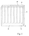
- FIG. 5 shows a perspective view of the layer stack 18 of FIG. 4.
- the layer stack 18 has a cuboid shape and has channels 19 formed as filtrate discharge channels in the exemplary embodiment.
- the one end 20 of the channels 19 each terminate in the layer stack 18.
- the opposite end 21 terminates in a side 22 of the layer stack 18. These ends 21 can be connected to a collecting duct, not shown. Since the ends 20 terminate in the layer stack 18 and are spaced from the side 22 opposite side 23, the channels 19 had to be not separately closed at one end.
- the layer stack 18 is suitable, since the inorganic layers 15 (FIG. 3) are porous, for use as a filter element. Liquid to be filtered is outside the stack of layers 18 and flows due to a pressure difference in the channels 19, from where the filtrate is discharged via the ends 21 of the channels 19.
- a structure is applied to the surface of a green layer by mechanical processing, and the green layer is then sintered. Before a sintering process, two or more layers may be laminated and sintered together. This procedure allows precise control over the location and dimensions of the structures.
Landscapes
- Chemical & Material Sciences (AREA)
- Engineering & Computer Science (AREA)
- Chemical Kinetics & Catalysis (AREA)
- Manufacturing & Machinery (AREA)
- Inorganic Chemistry (AREA)
- Ceramic Engineering (AREA)
- Materials Engineering (AREA)
- Structural Engineering (AREA)
- Organic Chemistry (AREA)
- Filtering Materials (AREA)
- Glass Compositions (AREA)
- Compositions Of Oxide Ceramics (AREA)
- Laminated Bodies (AREA)
Description
- Die Erfindung betrifft einen anorganischen Schichtenstapel gemäß Oberbegriff von Patentanspruch 6 und ein Verfahren zu dessen Herstellung gemäß Oberbegriff von Patentanspruch 1.
- Ein derartiger Schichtenstapel und ein derartiges Verfahren zu seiner Herstellung sind beispielsweise durch die WO 00/35561 A bekannt geworden.
- Aus der WO 00/35561 A sind eine Keramikschicht und ein Verfahren zu deren Herstellung bekannt, bei dem eine grüne Schicht durch Foliengießen hergestellt wird und in diese Schicht vor einer Sinterung eine Struktur eingeprägt wird. Die strukturierte Schicht wird weiter mit einer zweiten grünen Schicht vor dem Sintern verbunden, wodurch ein Multikanalflachmembranfilter entsteht. Die strukturierte Schicht weist eine nicht planare Struktur auf, die durch Prägen der Schicht mit zwei zueinander komplementären Prägestempeln erzeugt ist und dadurch beidseitig gewellt ist.
- Weiter sind auch aus der US-A-5 730 869 eine Keramikschicht und ein Verfahren zu deren Herstellung bekannt, wobei hier eine Gussmasse in die Form einer ungesinterten Grünfolie überführt wird und an der durch Foliengießen hergestellten Schicht ("Spacer") eine rinnenartige Struktur durch mechanische Bearbeitung eingebracht wird. Durch Abdecken des mit einer Schicht verbundenen Spacers mit einer weiteren Schicht werden Kanäle gebildet, die somit durch einen Dreischichtaufbau ausgebildet sind.
- Schließlich offenbart die DE 100 39 272 C ein Verfahren zur Herstellung eines keramischen Filterelements durch Schlickerguss von Stützkörpern aus keramischen Materialien. Dabei wird ein Zwischenkörper als Gießkern verwendet, der aus einem unter Wärmeeinfluss, also z.B. beim Sintern, flüchtigen Material besteht und eine kanalartige Struktur in den Stützkörpern abbildet.
- Weiterhin ist aus der DE 43 29 473 C1 eine anorganische Schicht bekannt, die an ihrer einen Oberfläche im Querschnitt halbkreisförmige Rinnen aufweist. Die anorganische Schicht ist porös ausgebildet und kann als Filterschicht eingesetzt werden. Aufgrund der halbkreisförmigen Ausführung der Rinnen kann der Differenzdruck ohne Auftreten von Zugspannung in der Schicht aufgenommen werden. Insbesondere wenn zwei bekannte poröse strukturierte anorganische Schichten miteinander verbunden werden, werden Filtratsammelkanäle ausgebildet. Allerdings sind diese Kanäle an beiden Seiten offen. Um ein Filtermodul auszubilden, muss eine Seite verschlossen, insbesondere verödet werden. Ein Verfahren zur Herstellung der anorganischen Schicht ist in dieser Druckschrift nicht beschrieben.
- Aufgabe der vorliegenden Erfindung ist es, bei einem Verfahren der eingangs genannten Art die Herstellung eines Schichtstapels zu vereinfachen und einen entsprechenden Schichtstapel vorzustellen.
- Gelöst wird diese Aufgabe erfindungsgemäß durch ein Verfahren zur Herstellung eines Schichtenstapels mit den Merkmalen des Patentanspruchs 1. Eine grüne Schicht ist eine Schicht, die Partikel, insbesondere Keramikpartikel, enthält und die zu einer porösen oder dichten Schicht gesintert werden kann. Eine grüne Schicht ist relativ leicht mechanisch bearbeitbar, so dass nahezu beliebige Strukturen in die Oberfläche der Schicht eingebracht werden können. Durch den Sintervorgang werden diese eingebrachten Strukturen dann verfestigt.
- Durch die eine oder mehreren rinnenartigen Strukturen können, insbesondere durch Verbindung mit anderen gleichartigen anorganischen Schichten, Kavitäten und Kanäle zum Abführen von Filtrat ausgebildet werden. Wenn eine derart strukturierte Oberfläche mit einer anderen Schicht abgedeckt wird, entstehen Kanäle, die an einem Ende verschlossen sind. Die rinnenartige Struktur ist so eingebracht, dass das andere Ende der rinnenartigen Struktur in eine andere rinnenartige Struktur mündet oder in einer Seite der grünen Schicht endet. Endet die rinnenartige Struktur dagegen in der Seite der Schicht, dann kann direkt an eine Rinne, bzw. wenn die Rinne durch Abdeckung mit einer anderen Schicht zu einem Kanal wird, an den Kanal ein Sammelkanal angeschlossen werden. Diese Ausführungsform ermöglicht eine einfache und sichere Abdichtung von dem aus der Schicht austretenden Kanal mit dem Sammelkanal.
- Besonders bevorzugt ist es, wenn die Struktur durch Fräsen, Laserschneiden oder Prägen eingebracht wird. Insbesondere das Fräsen ist vorteilhaft, wenn die anorganische Schicht als Filterschicht eingesetzt werden soll. Im Gegensatz zum Prägen, wo Material verdrängt wird, wird beim Fräsen Material entfernt. Bereiche der grünen Schicht werden nicht schon vor dem Sintern verdichtet, so dass eine homogene grüne Schicht erhalten bleibt, die sich beim Sintern gleichmäßig verdichten kann. Dadurch können Inhomogenitäten, die beim Filtern stören, vermieden werden. Wird die mechanische Bearbeitung mittels Fräsen durchgeführt, können sehr kleine Strukturen bzw. Rinnen, insbesondere mit freien Querschnitten < 0,4 mm, erzeugt werden. Derartig hergestellte Schichten lassen sich besonders leicht und klein ausbilden. Über den Bearbeitungsschritt Fräsen lassen sich Rinnen in einem beliebigen Querschnitt ausbilden und die Anordnung der Rinne in der Oberfläche der anorganischen Schicht ist beliebig.
- Besonders vorteilhaft ist es, wenn eine fächerartige Struktur eingebracht wird. Dadurch können die Rinnen auf einen Sammelkanal ausgerichtet werden und kann die Filtratabführung beschleunigt werden.
- Insbesondere, wenn die grüne Schicht durch Foliengießen hergestellt wird, lassen sich nahezu beliebige Geometrien einer anorganischen Schicht herstellen. Wenn vor dem Einbringen der rinnenartigen Struktur eine erste und zweite grüne Schicht verbunden werden, wobei mindestens eine der Schichten strukturiert wird, können die Eigenschaften der Schicht, insbesondere deren Filtereigenschaften, durch die Wahl unterschiedlicher Materialien in den Schichten oder unterschiedlicher Teilchengrößen in den Schichten beeinflusst werden. Die Teilchen können dabei verschiedene Gestalten aufweisen, zum Beispiel können sie sphärisch, plättchenförmig oder faserförmig ausgebildet sein. Durch die Wahl der Teilchengröße kann die Porosität der anorganischen Schicht beeinflusst werden. Wird die grüne Schicht durch Extrusion hergestellt, so ist es beim Extrusionsvorgang gleichzeitig möglich, die Struktur in die Oberfläche der Schicht einzubringen.
- Die in den grünen Schichten eingesetzten keramischen Werkstoffe sind vorzugsweise von Metall(misch)oxiden und Carbiden, Nitriden, Boriden, Siliciden und Carbonitriden von Metallen und Nichtmetallen abgeleitet. Beispiele hierfür sind Al2O3, teil- und vollstabilisiertes ZrO2, Mullit, Cordierit, Perowskite, Spinelle, zum Beispiel BaTiO3, PZT, PLZT, sowie SiC, Si3N4, B4C, BN, MOSi2, TiB2, TiN, TiC und Ti(C,N). Es versteht sich, dass diese Aufzählung nicht vollständig ist. Selbstverständlich können auch Mischungen von Oxiden bzw. Nichtoxiden und Mischungen aus Oxiden und Nichtoxiden eingesetzt werden.
- Bei einer bevorzugten weiteren Ausgestaltung des Verfahrens wird die erste Schicht zu einer grobporigen Trägerschicht und die zweite Schicht zu einer feinporigeren Funktionsschicht gesintert. Dabei stellt die feinporigere Funktionsschicht die filternde Schicht dar. Die grobporigere Trägerschicht stützt die feinporigere Funktionsschicht. In der Trägerschicht werden die rinnenartigen Strukturen ausgebildet. Nach dem Sintern erhält man einen Schichtstapel bzw. Keramikverbund.
- Wenn zwei grüne Schichten oder Schichtstapel an ihren strukturierten Oberflächen miteinander laminiert werden, können Filtratabführkanäle besonders einfach realisiert werden. Dabei können die rinnenartigen Strukturen nur an der Oberfläche einer Schicht oder an den Oberflächen beider Schichten ausgebildet sein. Wenn die Schichten miteinander verbunden sind, können die rinnenartigen Strukturen versetzt angeordnet sein oder sich gegenüberliegen. Liegen sie sich gegenüber, werden im erhaltenen Schichtenstapel Kanäle mit großem Querschnitt ausgebildet.
- In den Rahmen der Erfindung fällt auch ein anorganischer Schichtenstapel mit den Merkmalen des Patentanspruchs 6. Die poröse Schicht kann als Filterelement verwendet werden und die rinnenartigen Strukturen können als Filtratsammelstrukturen verwendet werden. Das Ende, das an der Seite der Schicht endet, stellt eine Austrittsöffnung dar, die beispielsweise mit einem Filtratsammelkanal verbunden werden kann.
- Bei einer alternativen Ausführungsform mündet das andere Ende der rinnenartigen Struktur in eine Vertiefung, insbesondere eine andere rinnenartige Struktur. Dadurch können mehrere rinnenartige Strukturen in einer gemeinsamen Rinne zusammengeführt werden.
- Bei einer Ausgestaltung der Erfindung ist vorgesehen, dass die mindestens eine rinnenartige Struktur im Querschnitt U-förmig oder rechteckig oder vieleckig ausgebildet ist.
- Bei einer vorteilhaften Ausgestaltung ist mindestens eine feinporigere und eine grobporigere Schicht vorgesehen, wobei die grobporigere Schicht die rinnenartige Struktur aufweist. Dabei kann die grobporigere Schicht als Trägerschicht für die feinporigere Funktionsschicht, die die eigentliche filternde Schicht ist, verwendet werden. Die Trägerschicht verleiht dem gesamten Schichtenstapel eine höhere Stabilität. Bei einer bevorzugten Ausführungsform ist die Schicht mit ihrer strukturierten Oberfläche an einer anderen Schicht fixiert. Zwischen der strukturierten Oberfläche und der anderen Schicht bilden sich aufgrund der rinnenartigen Strukturen Kanäle aus. Diese Kanäle können als Filtratabführkanäle verwendet werden, insbesondere wenn die Schichten poröse Schichten sind. Die miteinander verbundenen Schichten können dieselbe oder eine unterschiedliche Porosität und dieselbe oder unterschiedliche Dicken aufweisen.
- Bei einer bevorzugten Weiterbildung ist auch die andere Schicht an einer Oberfläche strukturiert und sind die beiden strukturierten Oberflächen aneinander fixiert. Durch diese Maßnahme können Filtratabführkanäle mit großem Querschnitt erzeugt werden. Die so beschaffenen Filtratabführkanäle sind an einem Ende verschlossen, wenn in den strukturierten Oberflächen rinnenartige Strukturen eingebracht sind, die mit einem Ende in der Schicht enden. Die durch eine Strukturierung erreichten Ausnehmungsformen können beim Zusammenfügen von zwei Schichten aufeinander deckungsgleich oder versetzt zueinander angeordnet sein.
- Die zwischen den Schichten ausgebildeten Kanäle können grundsätzlich beliebige Querschnitte aufweisen. Besonders bevorzugt sind jedoch Kanäle mit quadratischem, viereckigem oder vieleckigem Querschnitt.
- Besonders bevorzugt ist es, wenn die Kanäle in der Schicht bzw. dem Schichtenstapel zusammengeführt sind und eine gemeinsame Austrittsöffnung aufweisen. Insbesondere, wenn aus den Schichten Filterelemente hergestellt werden, kann das in den Filtratabführkanälen abgeführte Filtrat durch eine gemeinsame Austrittsöffnung aus dem Filterelement entnommen werden. Dadurch wird eine einfache Anbindung an einen Filtratsammelkanal ermöglicht.
- Für die Schicht sind nahezu beliebige geometrische Gestalten denkbar. Besonders bevorzugt ist es jedoch, wenn die Schicht bzw. der Schichtenstapel quaderförmig oder zylindrisch ausgebildet ist.
- Wenn in den aus den Schichten gebildeten Filterelementen sehr feine Strukturen ausgebildet sind, die insbesondere durch Fräsen der Schichten einfach erzeugt werden können, können sehr kleine und leichte Filterelemente Material sparend realisiert werden.
- Weitere Merkmale und Vorteile der Erfindung ergeben sich aus der nachfolgenden Beschreibung von Ausführungsbeispielen der Erfindung, anhand der Figuren der Zeichnung, die erfindungswesentliche Einzelheiten zeigen, und aus den Ansprüchen. Die einzelnen Merkmale können je einzeln für sich oder zu mehreren in beliebiger Kombination bei einer Variante der Erfindung verwirklicht sein.
- Ausführungsbeispiele der erfindungsgemäßen anorganischen Schicht sind in der schematischen Zeichnung dargestellt und werden in der nachfolgenden Beschreibung erläutert. Es zeigt:
- Fig. 1
- eine Draufsicht auf eine anorganische Schicht mit rinnenartigen Strukturen;
- Fig. 2
- einen Querschnitt durch eine anorganische Schicht mit rinnenartigen Strukturen;
- Fig. 3
- einen Querschnitt durch eine anorganische Schicht mit rinnenartigen Strukturen eines anderen Querschnitts;
- Fig. 4
- Zwei Schichten gemäß der Fig. 3 in zusammengefügtem Zustand;
- Fig. 5
- eine perspektivische Ansicht eines Schichtenstapels, in dessen Innerem Kanäle ausgebildet sind.
- Fig. 1 zeigt eine Draufsicht auf eine anorganische Schicht 1, in deren Oberfläche rinnenartige Strukturen 2 in Fächerform ausgebildet sind. Die rinnenartigen Strukturen 2 enden mit ihrem einen Ende 3 in der anorganischen Schicht 1. Mit ihrem anderen Ende 4 münden die rinnenartigen Strukturen 2 in einer Vertiefung 5, wobei die Vertiefung 5 tiefer als die rinnenartigen Strukturen 2 sein kann. Der Rinnengrund der rinnenartigen Strukturen 2 kann jedoch auch mit dem Grund der Vertiefung 5 fluchten. Die Vertiefung 5 mündet in einer Seite 6 der anorganischen Schicht 1.
- Fig. 2 zeigt einen Querschnitt durch eine anorganische Schicht 10, in die parallel zueinander verlaufende rinnenartige Strukturen 11 durch Fräsen eingebracht wurden, wobei die rinnenartigen Strukturen 11 einen fünfeckigen Querschnitt aufweisen. Werden zwei solcher anorganischen Schichten 10 mit ihren strukturierten Oberflächen 12 miteinander verbunden, so entstehen im Querschnitt achteckige Kanäle.
- In der Fig. 3 ist ein Schnitt durch eine anorganische Schicht 15 gezeigt, wobei an der Oberfläche 16 rinnenartige Strukturen 17 ausgebildet sind, die einen rechteckigen Querschnitt aufweisen.
- In der Fig. 4 ist ein Querschnitt durch einen Schichtenstapel 18 gezeigt, der aus zwei Schichten 15 gemäß der Fig. 3 hergestellt wurde. Dabei wurden zwei anorganische Schichten an ihren strukturierten Oberflächen miteinander verbunden. Dadurch wurden im Querschnitt rechteckige Kanäle 19 ausgebildet. Nach dem Sintern stellt der Schichtenstapel 18 eine Schicht mit innenliegenden Kanälen dar.
- In der Fig. 5 ist eine perspektivische Ansicht des Schichtenstapels 18 der Fig. 4 gezeigt. Der Schichtenstapel 18 hat eine Quaderform und weist im Ausführungsbeispiel als Filtratabführkanäle ausgebildete Kanäle 19 auf. Das eine Ende 20 der Kanäle 19 endet jeweils im Schichtenstapel 18. Das gegenüberliegende Ende 21 endet in einer Seite 22 des Schichtenstapels 18. Diese Enden 21 können mit einem nicht dargestellten Sammelkanal verbunden werden. Da die Enden 20 im Schichtenstapel 18 enden und von der der Seite 22 gegenüberliegenden Seite 23 beabstandet sind, mussten die Kanäle 19 nicht extra an einem Ende verschlossen werden. Der Schichtenstapel 18 eignet sich, da die anorganischen Schichten 15 (Fig. 3) porös ausgebildet sind, zum Einsatz als Filterelement. Zu filternde Flüssigkeit steht außen am Schichtenstapel 18 an und fließt aufgrund einer Druckdifferenz in die Kanäle 19, von wo aus das Filtrat über die Enden 21 der Kanäle 19 abgeführt wird.
- Bei einem Verfahren zur Herstellung einer strukturierten anorganischen Schicht 1, insbesondere einer Keramikschicht, wird an der Oberfläche einer grünen Schicht eine Struktur durch mechanische Bearbeitung eingebracht, und die grüne Schicht wird anschließend gesintert. Vor einem Sinterungsprozess können zwei oder mehr Schichten laminiert und gemeinsam gesintert werden. Diese Vorgehensweise erlaubt eine genaue Kontrolle über die Lage und Abmessungen der Strukturen.
Claims (11)
- Verfahren zur Herstellung eines Schichtenstapels (18), der strukturierte anorganische poröse Schichten (1, 10, 15), insbesondere Keramikschichten, aufweist, wobei an einer der Oberflächen (12, 16) einer grünen Schicht mindestens eine rinnenartige Struktur (2, 11, 17) durch mechanische Bearbeitung eingebracht wird und die grüne Schicht anschließend gesintert wird, wobei die rinnenartige Struktur (2, 11, 17) so eingebracht wird, dass sie zumindest einenends in der grünen Schicht endet, und wobei die grüne Schicht durch Foliengießen oder Extrudieren hergestellt wird,
dadurch gekennzeichnet,
dass zwei grüne Schichten an der strukturierten Oberfläche (12, 16) unter Bildung von Kanälen (19), die an einem Ende (20) verschlossen sind, miteinander laminiert werden und die rinnenartige Struktur (2, 11, 17) so eingebracht wird, dass das andere Ende (4) der rinnenartigen Struktur in einer Seite der grünen Schicht mündet. - Verfahren nach Anspruch 1, dadurch gekennzeichnet, dass die rinnenartige Struktur (2, 11, 17) durch Fräsen oder Laserschneiden oder Prägen eingebracht wird.
- Verfahren nach einem der vorhergehenden Ansprüche, dadurch gekennzeichnet, dass eine fächerartige Struktur (2) eingebracht wird.
- Verfahren nach einem der vorhergehenden Ansprüche, dadurch gekennzeichnet, dass vor dem Einbringen der rinnenartigen Struktur (2, 11, 17) eine erste und zweite grüne Schicht verbunden werden, wobei mindestens eine der Schichten strukturiert wird.
- Verfahren nach Anspruch 4, dadurch gekennzeichnet, dass die erste Schicht zu einer grobporigen Trägerschicht und die zweite Schicht zu einer feinporigeren Funktionsschicht gesintert wird.
- Anorganischer Schichtenstapel (18) umfassend eine durch Foliengießen oder Extrudieren einer grünen Schicht hergestellte anorganische poröse Schicht (1, 10, 15), insbesondere Keramikschicht, mit mindestens einer an ihrer Oberfläche (12, 16) ausgebildeten rinnenartigen Struktur (2, 11, 17), die einenends in der Schicht (1, 10, 15) endet, sowie eine andere anorganische Schicht, insbesondere Keramikschicht,
dadurch gekennzeichnet,
dass die Schicht (1, 10, 15) mit ihrer strukturierten Oberfläche (12, 16) unter Bildung von Kanälen (19), die an einem Ende (20) verschlossen sind, an der anderen Schicht fixiert ist und das andere Ende (4) der rinnenartigen Struktur (2, 11, 17) an einer Seite (22) der Schicht (1, 10, 16) endet. - Schichtenstapel nach Anspruch 6, dadurch gekennzeichnet, dass die mindestens eine rinnenartige Struktur (2, 11, 17) im Querschnitt u-förmig oder rechteckig oder vieleckig ausgebildet ist.
- Schichtenstapel nach Anspruch 6 oder 7, dadurch gekennzeichnet, dass eine feinporige und eine grobporigere Schicht vorgesehen sind, wobei die grobporigere Schicht die rinnenartige Struktur (2, 11, 17) aufweist.
- Schichtenstapel nach einem der Ansprüche 6 bis 8, dadurch gekennzeichnet, dass die andere Schicht an einer Oberfläche (12, 16) strukturiert ist und die beiden strukturierten Oberflächen aneinander fixiert sind.
- Schichtenstapel nach einem der Ansprüche 6 bis 9, dadurch gekennzeichnet, dass die Kanäle (19) in der Schicht zusammengeführt sind und eine gemeinsame Austrittsöffnung aufweisen.
- Schichtenstapel nach einem der Ansprüche 6 bis 10, dadurch gekennzeichnet, dass die Schicht quaderförmig oder zylindrisch, insbesondere scheibenförmig, ausgebildet ist.
Applications Claiming Priority (3)
| Application Number | Priority Date | Filing Date | Title |
|---|---|---|---|
| DE2003105866 DE10305866B4 (de) | 2003-02-13 | 2003-02-13 | Anorganische Schicht |
| DE10305866 | 2003-02-13 | ||
| PCT/DE2003/003832 WO2004071630A1 (de) | 2003-02-13 | 2003-11-19 | Anorganische schicht |
Publications (2)
| Publication Number | Publication Date |
|---|---|
| EP1601449A1 EP1601449A1 (de) | 2005-12-07 |
| EP1601449B1 true EP1601449B1 (de) | 2006-09-27 |
Family
ID=32841646
Family Applications (1)
| Application Number | Title | Priority Date | Filing Date |
|---|---|---|---|
| EP20030815820 Expired - Lifetime EP1601449B1 (de) | 2003-02-13 | 2003-11-19 | Anorganische schichtenstapel und verfahren zu seiner herstellung |
Country Status (7)
| Country | Link |
|---|---|
| US (1) | US20070110988A1 (de) |
| EP (1) | EP1601449B1 (de) |
| AT (1) | ATE340635T1 (de) |
| AU (1) | AU2003300486A1 (de) |
| DE (2) | DE10305866B4 (de) |
| ES (1) | ES2271703T3 (de) |
| WO (1) | WO2004071630A1 (de) |
Families Citing this family (4)
| Publication number | Priority date | Publication date | Assignee | Title |
|---|---|---|---|---|
| DE102009006953B3 (de) * | 2009-01-30 | 2010-08-19 | Saint-Gobain Industriekeramik Rödental GmbH | Verfahren zur Herstellung eines keramischen Absorberkörpers für Solarstrahlung und Absorberkörper |
| US8794298B2 (en) | 2009-12-30 | 2014-08-05 | Rolls-Royce Corporation | Systems and methods for filtering molten metal |
| DE102013111093A1 (de) * | 2013-10-08 | 2015-04-09 | Napt - New Advanced Process Technology Ag | Keramikelement für Fluidtrennvorrichtung |
| DE102013105584A1 (de) * | 2013-05-30 | 2014-12-04 | Napt - New Advanced Process Technology Ag | Keramikelement für Fluidtrennvorrichtung |
Family Cites Families (10)
| Publication number | Priority date | Publication date | Assignee | Title |
|---|---|---|---|---|
| US4960449A (en) * | 1989-02-28 | 1990-10-02 | Cummins Engine Company, Inc. | Ceramic particulate trap and method of making the same |
| GB8914023D0 (en) * | 1989-06-19 | 1989-08-09 | Alcan Int Ltd | Porous ceramic membrane method |
| US5306646A (en) * | 1992-12-23 | 1994-04-26 | Martin Marietta Energy Systems, Inc. | Method for producing textured substrates for thin-film photovoltaic cells |
| DE4329473C1 (de) * | 1993-09-01 | 1994-08-18 | Chmiel Horst | Druckstabile anorganische Membranen |
| US5730869A (en) * | 1995-01-28 | 1998-03-24 | Koppe; Franz | Porous ceramic filter |
| US5851636A (en) * | 1995-12-29 | 1998-12-22 | Lantec Products, Inc. | Ceramic packing with channels for thermal and catalytic beds |
| DE19857590B4 (de) * | 1998-12-14 | 2004-09-09 | Fraunhofer-Gesellschaft zur Förderung der angewandten Forschung e.V. | Keramische Flachmembran und Verfahren zu ihrer Herstellung |
| DE19938674C2 (de) * | 1999-08-06 | 2001-10-31 | Fraunhofer Ges Forschung | Flachmembranstapel und Verfahren zu seiner Herstellung |
| DE10039272C1 (de) * | 2000-08-11 | 2002-01-24 | Aaflowsystems Gmbh & Co Kg | Plattenförmiger Filtrationskörper |
| WO2003035578A1 (en) * | 2001-10-26 | 2003-05-01 | Zakrytoe Aktsionernoe Obschestvo Nauchno-Tekhnicheskiy Tsentr 'bakor' | Ceramic filtering element and method for producing said element |
-
2003
- 2003-02-13 DE DE2003105866 patent/DE10305866B4/de not_active Expired - Fee Related
- 2003-11-19 AT AT03815820T patent/ATE340635T1/de not_active IP Right Cessation
- 2003-11-19 US US10/545,018 patent/US20070110988A1/en not_active Abandoned
- 2003-11-19 ES ES03815820T patent/ES2271703T3/es not_active Expired - Lifetime
- 2003-11-19 AU AU2003300486A patent/AU2003300486A1/en not_active Abandoned
- 2003-11-19 EP EP20030815820 patent/EP1601449B1/de not_active Expired - Lifetime
- 2003-11-19 DE DE50305215T patent/DE50305215D1/de not_active Expired - Lifetime
- 2003-11-19 WO PCT/DE2003/003832 patent/WO2004071630A1/de not_active Ceased
Also Published As
| Publication number | Publication date |
|---|---|
| DE50305215D1 (de) | 2006-11-09 |
| ES2271703T3 (es) | 2007-04-16 |
| ATE340635T1 (de) | 2006-10-15 |
| DE10305866A1 (de) | 2004-09-09 |
| DE10305866B4 (de) | 2007-02-08 |
| EP1601449A1 (de) | 2005-12-07 |
| WO2004071630A1 (de) | 2004-08-26 |
| AU2003300486A1 (en) | 2004-09-06 |
| US20070110988A1 (en) | 2007-05-17 |
Similar Documents
| Publication | Publication Date | Title |
|---|---|---|
| EP0817723B1 (de) | Verfahren zur herstellung von schwindungsangepassten keramik-verbundwerkstoffen | |
| DE102017002067B4 (de) | Wabenstruktur | |
| DE3541372A1 (de) | Abgasreinigungsfilter und verfahren zu seiner herstellung | |
| DE60307277T2 (de) | Anodengestützte brennstoffzelle | |
| EP0651698B1 (de) | Verbundsysteme mit mindestens zwei anorganischen keramischen schichten und verfahren zu deren herstellung | |
| EP1144089B1 (de) | Keramische flachmembran und verfahren zu ihrer herstellung | |
| DE10361346A1 (de) | Platten-Wärmeübertrager, Verfahren zur Herstellung eines Platten-Wärmeübertragers und keramischer Faserverbundwerkstoff, insbesondere für einen Platten-Wärmeübertrager | |
| DE102014003838B4 (de) | Wabenstruktur | |
| EP2066878A1 (de) | Filterelement, insbesondere zur filterung von abgasen einer brennkraftmaschine | |
| DE10305864B4 (de) | Verfahren zur Herstellung eines mehrlagigen porösen Keramikverbundes | |
| EP3826753B1 (de) | Filterelement für einen partikelfilter sowie abgaspartikelfilter | |
| DE10305866B4 (de) | Anorganische Schicht | |
| DE102020001168A1 (de) | Beschichtungsmaterial für Wabenstruktur, äußere periphere Beschichtung der Wabenstruktur und Wabenstruktur mit äußerer peripherer Beschichtung | |
| EP0750597B1 (de) | Verfahren zur herstellung von keramischen verbundkörpern | |
| WO2004067154A1 (de) | Mehrlagiger keramikverbund | |
| DE102014003835B4 (de) | Wabenstruktur | |
| EP2147469B1 (de) | Piezoelektrisches vielschichtbauelement | |
| DE112017006597B4 (de) | Poröser Wabenfilter | |
| DE102014018481A1 (de) | Keramische Filtermembran und Filtermodul | |
| DE10329229B3 (de) | Flachmembranstapel und Verfahren zur Herstellung einer solchen | |
| DE69323177T2 (de) | Anorganische filterstruktur mit mindestens einem integralen kanalnetzwerk für die zu filternde flüssigkeit und/oder für das genommene filtrat | |
| DE19938674C2 (de) | Flachmembranstapel und Verfahren zu seiner Herstellung | |
| DE102006022600B4 (de) | Herstellungsverfahren eines Piezoaktors | |
| DE102019108035A1 (de) | Poröser keramikkörper und verfahren für dessen herstellung sowie staubsammelfilter | |
| EP1370347A1 (de) | Filtrationseinheit |
Legal Events
| Date | Code | Title | Description |
|---|---|---|---|
| PUAI | Public reference made under article 153(3) epc to a published international application that has entered the european phase |
Free format text: ORIGINAL CODE: 0009012 |
|
| 17P | Request for examination filed |
Effective date: 20050913 |
|
| AK | Designated contracting states |
Kind code of ref document: A1 Designated state(s): AT BE BG CH CY CZ DE DK EE ES FI FR GB GR HU IE IT LI LU MC NL PT RO SE SI SK TR |
|
| AX | Request for extension of the european patent |
Extension state: AL LT LV MK |
|
| RIN1 | Information on inventor provided before grant (corrected) |
Inventor name: BINKLE, OLAF Inventor name: NONNINGER, RALPH |
|
| GRAP | Despatch of communication of intention to grant a patent |
Free format text: ORIGINAL CODE: EPIDOSNIGR1 |
|
| RTI1 | Title (correction) |
Free format text: STACK OF INORGANIC LAYERS AND METHOD FOR PRODUCTION THEREOF |
|
| DAX | Request for extension of the european patent (deleted) | ||
| GRAS | Grant fee paid |
Free format text: ORIGINAL CODE: EPIDOSNIGR3 |
|
| GRAA | (expected) grant |
Free format text: ORIGINAL CODE: 0009210 |
|
| AK | Designated contracting states |
Kind code of ref document: B1 Designated state(s): AT BE BG CH CY CZ DE DK EE ES FI FR GB GR HU IE IT LI LU MC NL PT RO SE SI SK TR |
|
| PG25 | Lapsed in a contracting state [announced via postgrant information from national office to epo] |
Ref country code: IT Free format text: LAPSE BECAUSE OF FAILURE TO SUBMIT A TRANSLATION OF THE DESCRIPTION OR TO PAY THE FEE WITHIN THE PRESCRIBED TIME-LIMIT;WARNING: LAPSES OF ITALIAN PATENTS WITH EFFECTIVE DATE BEFORE 2007 MAY HAVE OCCURRED AT ANY TIME BEFORE 2007. THE CORRECT EFFECTIVE DATE MAY BE DIFFERENT FROM THE ONE RECORDED. Effective date: 20060927 Ref country code: FI Free format text: LAPSE BECAUSE OF FAILURE TO SUBMIT A TRANSLATION OF THE DESCRIPTION OR TO PAY THE FEE WITHIN THE PRESCRIBED TIME-LIMIT Effective date: 20060927 Ref country code: SK Free format text: LAPSE BECAUSE OF FAILURE TO SUBMIT A TRANSLATION OF THE DESCRIPTION OR TO PAY THE FEE WITHIN THE PRESCRIBED TIME-LIMIT Effective date: 20060927 Ref country code: CZ Free format text: LAPSE BECAUSE OF FAILURE TO SUBMIT A TRANSLATION OF THE DESCRIPTION OR TO PAY THE FEE WITHIN THE PRESCRIBED TIME-LIMIT Effective date: 20060927 Ref country code: RO Free format text: LAPSE BECAUSE OF FAILURE TO SUBMIT A TRANSLATION OF THE DESCRIPTION OR TO PAY THE FEE WITHIN THE PRESCRIBED TIME-LIMIT Effective date: 20060927 Ref country code: SI Free format text: LAPSE BECAUSE OF FAILURE TO SUBMIT A TRANSLATION OF THE DESCRIPTION OR TO PAY THE FEE WITHIN THE PRESCRIBED TIME-LIMIT Effective date: 20060927 Ref country code: NL Free format text: LAPSE BECAUSE OF FAILURE TO SUBMIT A TRANSLATION OF THE DESCRIPTION OR TO PAY THE FEE WITHIN THE PRESCRIBED TIME-LIMIT Effective date: 20060927 Ref country code: IE Free format text: LAPSE BECAUSE OF FAILURE TO SUBMIT A TRANSLATION OF THE DESCRIPTION OR TO PAY THE FEE WITHIN THE PRESCRIBED TIME-LIMIT Effective date: 20060927 |
|
| REG | Reference to a national code |
Ref country code: GB Ref legal event code: FG4D Free format text: NOT ENGLISH |
|
| GBT | Gb: translation of ep patent filed (gb section 77(6)(a)/1977) |
Effective date: 20060927 |
|
| REG | Reference to a national code |
Ref country code: CH Ref legal event code: EP |
|
| REG | Reference to a national code |
Ref country code: IE Ref legal event code: FG4D Free format text: LANGUAGE OF EP DOCUMENT: GERMAN |
|
| REF | Corresponds to: |
Ref document number: 50305215 Country of ref document: DE Date of ref document: 20061109 Kind code of ref document: P |
|
| PG25 | Lapsed in a contracting state [announced via postgrant information from national office to epo] |
Ref country code: MC Free format text: LAPSE BECAUSE OF NON-PAYMENT OF DUE FEES Effective date: 20061130 Ref country code: BE Free format text: LAPSE BECAUSE OF NON-PAYMENT OF DUE FEES Effective date: 20061130 |
|
| PG25 | Lapsed in a contracting state [announced via postgrant information from national office to epo] |
Ref country code: SE Free format text: LAPSE BECAUSE OF FAILURE TO SUBMIT A TRANSLATION OF THE DESCRIPTION OR TO PAY THE FEE WITHIN THE PRESCRIBED TIME-LIMIT Effective date: 20061227 Ref country code: DK Free format text: LAPSE BECAUSE OF FAILURE TO SUBMIT A TRANSLATION OF THE DESCRIPTION OR TO PAY THE FEE WITHIN THE PRESCRIBED TIME-LIMIT Effective date: 20061227 Ref country code: BG Free format text: LAPSE BECAUSE OF FAILURE TO SUBMIT A TRANSLATION OF THE DESCRIPTION OR TO PAY THE FEE WITHIN THE PRESCRIBED TIME-LIMIT Effective date: 20061227 |
|
| NLV1 | Nl: lapsed or annulled due to failure to fulfill the requirements of art. 29p and 29m of the patents act | ||
| PG25 | Lapsed in a contracting state [announced via postgrant information from national office to epo] |
Ref country code: PT Free format text: LAPSE BECAUSE OF FAILURE TO SUBMIT A TRANSLATION OF THE DESCRIPTION OR TO PAY THE FEE WITHIN THE PRESCRIBED TIME-LIMIT Effective date: 20070313 |
|
| ET | Fr: translation filed | ||
| REG | Reference to a national code |
Ref country code: ES Ref legal event code: FG2A Ref document number: 2271703 Country of ref document: ES Kind code of ref document: T3 |
|
| RAP2 | Party data changed (patent owner data changed or rights of a patent transferred) |
Owner name: ITN NANOVATION AG |
|
| REG | Reference to a national code |
Ref country code: IE Ref legal event code: FD4D |
|
| PLBE | No opposition filed within time limit |
Free format text: ORIGINAL CODE: 0009261 |
|
| STAA | Information on the status of an ep patent application or granted ep patent |
Free format text: STATUS: NO OPPOSITION FILED WITHIN TIME LIMIT |
|
| 26N | No opposition filed |
Effective date: 20070628 |
|
| REG | Reference to a national code |
Ref country code: FR Ref legal event code: CD Ref country code: FR Ref legal event code: CJ |
|
| BERE | Be: lapsed |
Owner name: ITN NANOVATION G.M.B.H. Effective date: 20061130 |
|
| PG25 | Lapsed in a contracting state [announced via postgrant information from national office to epo] |
Ref country code: AT Free format text: LAPSE BECAUSE OF NON-PAYMENT OF DUE FEES Effective date: 20061119 |
|
| PG25 | Lapsed in a contracting state [announced via postgrant information from national office to epo] |
Ref country code: GR Free format text: LAPSE BECAUSE OF FAILURE TO SUBMIT A TRANSLATION OF THE DESCRIPTION OR TO PAY THE FEE WITHIN THE PRESCRIBED TIME-LIMIT Effective date: 20061228 |
|
| PG25 | Lapsed in a contracting state [announced via postgrant information from national office to epo] |
Ref country code: EE Free format text: LAPSE BECAUSE OF FAILURE TO SUBMIT A TRANSLATION OF THE DESCRIPTION OR TO PAY THE FEE WITHIN THE PRESCRIBED TIME-LIMIT Effective date: 20060927 |
|
| PG25 | Lapsed in a contracting state [announced via postgrant information from national office to epo] |
Ref country code: LU Free format text: LAPSE BECAUSE OF NON-PAYMENT OF DUE FEES Effective date: 20061119 Ref country code: TR Free format text: LAPSE BECAUSE OF FAILURE TO SUBMIT A TRANSLATION OF THE DESCRIPTION OR TO PAY THE FEE WITHIN THE PRESCRIBED TIME-LIMIT Effective date: 20060927 Ref country code: HU Free format text: LAPSE BECAUSE OF FAILURE TO SUBMIT A TRANSLATION OF THE DESCRIPTION OR TO PAY THE FEE WITHIN THE PRESCRIBED TIME-LIMIT Effective date: 20070328 Ref country code: LI Free format text: LAPSE BECAUSE OF NON-PAYMENT OF DUE FEES Effective date: 20071130 Ref country code: CH Free format text: LAPSE BECAUSE OF NON-PAYMENT OF DUE FEES Effective date: 20071130 |
|
| REG | Reference to a national code |
Ref country code: CH Ref legal event code: PL |
|
| PG25 | Lapsed in a contracting state [announced via postgrant information from national office to epo] |
Ref country code: CY Free format text: LAPSE BECAUSE OF FAILURE TO SUBMIT A TRANSLATION OF THE DESCRIPTION OR TO PAY THE FEE WITHIN THE PRESCRIBED TIME-LIMIT Effective date: 20060927 |
|
| REG | Reference to a national code |
Ref country code: FR Ref legal event code: PLFP Year of fee payment: 13 |
|
| PGFP | Annual fee paid to national office [announced via postgrant information from national office to epo] |
Ref country code: GB Payment date: 20151123 Year of fee payment: 13 Ref country code: DE Payment date: 20151126 Year of fee payment: 13 |
|
| PGFP | Annual fee paid to national office [announced via postgrant information from national office to epo] |
Ref country code: FR Payment date: 20151124 Year of fee payment: 13 Ref country code: ES Payment date: 20151124 Year of fee payment: 13 |
|
| REG | Reference to a national code |
Ref country code: DE Ref legal event code: R119 Ref document number: 50305215 Country of ref document: DE |
|
| GBPC | Gb: european patent ceased through non-payment of renewal fee |
Effective date: 20161119 |
|
| REG | Reference to a national code |
Ref country code: FR Ref legal event code: ST Effective date: 20170731 |
|
| PG25 | Lapsed in a contracting state [announced via postgrant information from national office to epo] |
Ref country code: FR Free format text: LAPSE BECAUSE OF NON-PAYMENT OF DUE FEES Effective date: 20161130 |
|
| PG25 | Lapsed in a contracting state [announced via postgrant information from national office to epo] |
Ref country code: DE Free format text: LAPSE BECAUSE OF NON-PAYMENT OF DUE FEES Effective date: 20170601 Ref country code: GB Free format text: LAPSE BECAUSE OF NON-PAYMENT OF DUE FEES Effective date: 20161119 |
|
| PG25 | Lapsed in a contracting state [announced via postgrant information from national office to epo] |
Ref country code: ES Free format text: LAPSE BECAUSE OF NON-PAYMENT OF DUE FEES Effective date: 20161120 |
|
| REG | Reference to a national code |
Ref country code: ES Ref legal event code: FD2A Effective date: 20181120 |