EP1600707B1 - Elektrisch beheizter Heisswasserbereiter - Google Patents
Elektrisch beheizter Heisswasserbereiter Download PDFInfo
- Publication number
- EP1600707B1 EP1600707B1 EP05107552A EP05107552A EP1600707B1 EP 1600707 B1 EP1600707 B1 EP 1600707B1 EP 05107552 A EP05107552 A EP 05107552A EP 05107552 A EP05107552 A EP 05107552A EP 1600707 B1 EP1600707 B1 EP 1600707B1
- Authority
- EP
- European Patent Office
- Prior art keywords
- container
- water heater
- water
- heater according
- heater
- Prior art date
- Legal status (The legal status is an assumption and is not a legal conclusion. Google has not performed a legal analysis and makes no representation as to the accuracy of the status listed.)
- Expired - Lifetime
Links
- XLYOFNOQVPJJNP-UHFFFAOYSA-N water Substances O XLYOFNOQVPJJNP-UHFFFAOYSA-N 0.000 title claims abstract description 104
- 229920003023 plastic Polymers 0.000 claims abstract description 8
- 239000004033 plastic Substances 0.000 claims abstract description 8
- 238000001746 injection moulding Methods 0.000 claims abstract description 4
- 238000010438 heat treatment Methods 0.000 claims description 21
- 239000000463 material Substances 0.000 claims description 2
- 238000005485 electric heating Methods 0.000 claims 1
- 239000012528 membrane Substances 0.000 abstract description 26
- 238000004026 adhesive bonding Methods 0.000 abstract 1
- 238000003466 welding Methods 0.000 abstract 1
- 238000004519 manufacturing process Methods 0.000 description 6
- 230000005484 gravity Effects 0.000 description 4
- 230000006870 function Effects 0.000 description 3
- 238000001514 detection method Methods 0.000 description 2
- 238000009434 installation Methods 0.000 description 2
- 230000001174 ascending effect Effects 0.000 description 1
- 230000006835 compression Effects 0.000 description 1
- 238000007906 compression Methods 0.000 description 1
- 238000011161 development Methods 0.000 description 1
- 230000018109 developmental process Effects 0.000 description 1
- 229920001971 elastomer Polymers 0.000 description 1
- 239000000806 elastomer Substances 0.000 description 1
- 239000008236 heating water Substances 0.000 description 1
- 238000002347 injection Methods 0.000 description 1
- 239000007924 injection Substances 0.000 description 1
- 230000000717 retained effect Effects 0.000 description 1
- 239000004065 semiconductor Substances 0.000 description 1
- 239000000725 suspension Substances 0.000 description 1
Images


Classifications
-
- F—MECHANICAL ENGINEERING; LIGHTING; HEATING; WEAPONS; BLASTING
- F24—HEATING; RANGES; VENTILATING
- F24H—FLUID HEATERS, e.g. WATER OR AIR HEATERS, HAVING HEAT-GENERATING MEANS, e.g. HEAT PUMPS, IN GENERAL
- F24H1/00—Water heaters, e.g. boilers, continuous-flow heaters or water-storage heaters
- F24H1/10—Continuous-flow heaters, i.e. heaters in which heat is generated only while the water is flowing, e.g. with direct contact of the water with the heating medium
- F24H1/101—Continuous-flow heaters, i.e. heaters in which heat is generated only while the water is flowing, e.g. with direct contact of the water with the heating medium using electric energy supply
- F24H1/102—Continuous-flow heaters, i.e. heaters in which heat is generated only while the water is flowing, e.g. with direct contact of the water with the heating medium using electric energy supply with resistance
-
- F—MECHANICAL ENGINEERING; LIGHTING; HEATING; WEAPONS; BLASTING
- F24—HEATING; RANGES; VENTILATING
- F24H—FLUID HEATERS, e.g. WATER OR AIR HEATERS, HAVING HEAT-GENERATING MEANS, e.g. HEAT PUMPS, IN GENERAL
- F24H9/00—Details
- F24H9/02—Casings; Cover lids; Ornamental panels
-
- F—MECHANICAL ENGINEERING; LIGHTING; HEATING; WEAPONS; BLASTING
- F24—HEATING; RANGES; VENTILATING
- F24H—FLUID HEATERS, e.g. WATER OR AIR HEATERS, HAVING HEAT-GENERATING MEANS, e.g. HEAT PUMPS, IN GENERAL
- F24H9/00—Details
- F24H9/18—Arrangement or mounting of grates or heating means
- F24H9/1809—Arrangement or mounting of grates or heating means for water heaters
- F24H9/1818—Arrangement or mounting of electric heating means
Definitions
- the present invention relates to an electric hot water heater according to the preamble of patent claim 1.
- Such a hot water heater is by document GB-A-1 162 049 already known the German utility model GM 6607855 describes a water heater with an internally electrically heated channel body, which is covered to form a closed water channel of two headers, wherein a head piece has means for wall suspension.
- the installation of this water heater requires disadvantageously that first the entire channel body must be mounted before the hot water heater can be further assembled.
- the present invention has for its object to provide a hot water heater of the type mentioned, which is inexpensive and easy to manufacture and has a compact design.
- the hot water heater may for example be a small memory and in particular a water heater.
- the assembly of all functional components on a container part the production is much easier because almost all assembly operations are performed on a single component.
- the assembly is facilitated in an assembly line in which a container part is passed through a plurality of assembly stations, in each of which functional components are mounted on the container part, wherein in one of these assembly stations remaining container parts can be mounted to completely build the container.
- all functional components are mounted on a container part, but it is also sufficient if at least the essential functional components of the hot water heater are mounted on one of the container parts.
- the essential functional components are, for example, the heating device, an inflow device, a drain device, a controller, a flow switch, display elements, Operating elements, temperature sensors or other components that serve the function and in particular the control of the hot water heater.
- the mounting container part, to which all, or at least the essential functional components of the hot water heater are mounted, can remain as the central component throughout the manufacturing process, to which all other, usually smaller components are grown.
- the arrangement of the heater in the container can be determined.
- the heater may be disposed within the container so that the heated portions of the heater can not come into contact with the container wall, so that a heater having a high power density can be used.
- a high performance in terms of the size of the hot water heater can be achieved.
- the container can be made of a non-temperature-resistant, inexpensive material such as plastic, since a safe distance of the heater to the wall can be ensured.
- the heater may be, for example, a tubular heater. The cost and size of the hot water heater can be reduced in this way.
- the container has fastening devices for mounting the hot water heater, wherein the fastening devices can also be designed exclusively on a container part.
- a container part can continue to be designed as a housing portion of the hot water heater.
- the rear wall of the hot water heater can be formed by a container part, wherein the container can be constructed from two container parts.
- the container part can for this purpose have two-dimensional extensions which form at least parts of the housing.
- a container part serving as the rear wall of the hot water heater has the means for mounting the hot water heater.
- the container and in particular a container part may have means for attaching a device hood, so that the mountability of a hood can be achieved with very little effort.
- this device can be a snap connection.
- the device hood can form the front wall of the hot water heater. If a container part is formed as a housing portion such as the rear wall and additionally has the means for attaching a hood, to complete the housing of the boiler after the assembly of all functional components on the container only the placement and locking of the hood is necessary.
- the assembly can be further simplified by at least one container part, are mounted on the functional parts, executed in two-component plastic injection molding.
- seals for the projecting into the container or associated with the container interior functional components in the production of the container part in question can already be formed in the right places, so that no additional operation for inserting seals is required.
- an elastomer can be used as one component.
- these seals may be provided for a heater protruding into the container or for a safety pressure relief valve connected to the container.
- membranes for example, to control switching functions by overshadowing in a container part a cavity or at least one depression and then a membrane extending over this depression of an elastic component.
- the container has an annular interior.
- the water to be heated can be passed through the container in such a way that it flows through the container in a single direction.
- the water can be guided in such a case over a distance along the heater, which corresponds substantially to the circumference of the annular container interior.
- the interior of the container is annular, the result is a container in the form of a torus.
- the annular interior does not necessarily have to be formed as a closed ring, but in particular may also be designed only as a horseshoe-shaped or U-shaped ring section.
- the annular or toroidal container has a feed device for water, which is arranged such that in the operating state of the hot water heater, the water flows through the container substantially against gravity. This ensures that the water rises from bottom to top in the container and possibly with the water introduced air bubbles are conveyed upwards against gravity. This has the advantage that no air bubbles are retained in the container.
- the container has a drainage device for water, which is arranged such that in the operating state of the hot water heater against the force of gravity ascending air bubbles are expelled by the water from the container.
- This has the advantage that air bubbles, which move against the force of gravity due to the flow of the water or solely by their own buoyancy force, do not accumulate at the upper end of the container and remain there. Remaining air bubbles could accumulate to an ever-expanding bubble and displace the water in the container so far until the heater is exposed. With an exposed heater, there is a risk that it will overheat and be damaged. To avoid this, it is envisaged to provide the drainage device at least near or directly at the point at which air bubbles could collect.
- a branch is provided, by means of which the water flowing in via an inlet device can be divided into two partial streams, for flowing through a container in two different directions.
- Each partial flow occurs with a low initial temperature and in particular only passes through half the length of the heating device in each case. This results in a better heat yield, ie the efficiency is improved because there is a high temperature difference between the incoming water and the heater in both partial streams at the water inlet. With such a high temperature gradient, the heat transfer from the heater to the water is improved.
- both partial flows can be heated separately.
- To each of the two partial streams can be provided with its own heating device. This has the advantage that both partial streams are separated and independently controllable. At a confluence of the two separate partial streams at the end of the heating section, the water streams, which may have different temperatures, can be mixed together again.
- the water flows clockwise in one partial flow and counterclockwise in the other partial flow.
- the two partial flows are brought together again at the end of the two sections and the heated water leaves the container via a common drainage device.
- the functional components can be arranged on a surface of the container part, which is surrounded by the annular interior of the container. This has the advantage that the inner area surrounded by the annular or toroidal container section can be used to save space for the reception of functional components. This results in a particularly compact design of the hot water heater.
- a membrane can or a Venturi nozzle can be arranged in a particularly advantageous manner such that the annular container interior extends around the membrane can or Venturi nozzle, so that these functional components are arranged in a space which in any case does not contribute to the container interior ,
- a membrane can or Venturi nozzle can be configured in a hot water heater according to the invention by two wells in each case designed a depression and therebetween, for example, the membrane is arranged, which is held between the two container parts and closes the two wells, so that the two wells two form separate pressure chambers by means of the membrane.
- the recess may be provided in only one of the two container parts and the other container part may be flat.
- Such a diaphragm can, in particular in conjunction with a venturi for detection the flow rate in a water heater are used. The flow rate can be taken into account when adjusting the heating power.
- An overpressure valve can be arranged on that container part which is free of the essential functional components. This has the particular advantage that after a release of the pressure relief valve leaking water can be kept away from the functional components. Since the functional components can also comprise electrical components, it makes sense if they do not come into contact with water.
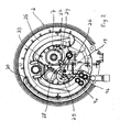
- the in Fig. 1 shown hot water heater is a water heater and has a container for heating the water, which consists of two container parts 1, 2, which consist for example of plastic and can be welded or glued together for connection, for example.
- a container for heating the water which consists of two container parts 1, 2, which consist for example of plastic and can be welded or glued together for connection, for example.
- an electric heater 4 is arranged in the form of a tubular heater, which is held in the upper container half 2 and self-supporting, so that the exact position of the heater 4 is set within the container 1, 2 and the heater 4 can not touch the container parts 1, 2.
- the heating device 4 has two heating circuits, which can be acted upon or switched on separately in order to be able to change the power supplied to the water.
- the two container parts 1, 2 include an annular interior 3, in which the water to be heated is circulated in a direction around, wherein the hot water heater has not shown inflow and outflow devices.
- the sections the heater 4, which extend through the upper container part 2, are sealed by means of seals 5 with respect to the upper container part 2, wherein the upper container part 2 is executed in two-component plastic injection molding and the seals 5 already in the production of the upper Container parts 2 have been formed in the bushings for the heater 4. To install the heater 4, this must be inserted only from below into the upper container part 2.
- the heating power is also controlled in part depending on the water flow, the water flow is measured by means of a membrane box 7, which is connected via a channel 10 with the interior 3 of the container.
- the membrane cell 7 has in its interior a membrane 8, which divides the interior of the membrane cell 7 into an upper and a lower cavity, of which the lower cavity is connected via the channel 10 with the interior 3 of the container 1, 2.
- the diaphragm cell 7 is arranged in the center of the annular interior 3.
- the two cavities of the membrane cell 7 are formed by depressions in the two container parts 1, 2, which come to lie one above the other when joining the two container parts 1, 2 and thus form the interior of the membrane cell 7.
- the membrane 8 is placed before joining between the two container parts 1, 2, so that the membrane 8 is held after joining the container parts 1, 2 between them and covers the two wells of the container parts 1, 2 and seals.
- the membrane 8 is biased by a arranged in the upper cavity compression spring 9 down into the lower cavity. As soon as water is drawn from the hot water heater or when hot water is tapped, the water begins to flow within the interior 3 and causes a pressure drop within the interior 3 at a Venturi nozzle (not shown).
- the venturi is connected to the space above the membrane 8 so that the pressure drop across the venturi causes the membrane 8 to deflect upward.
- a switching cam 11 is attached via a push rod, which is displaced vertically according to the pressure difference between the lower and the upper cavity of the diaphragm cell 7.
- the switching cam 11 has two lateral buttons, which act on microswitch 12, 13.
- the two buttons of the switching cam 11 are each ramps, so that the switching cam 11 widened towards the bottom and the buttons 11 in an upward movement of the control cam 11 extend to the outside.
- the two microswitches 12, 13 can switch the two heating circuits separately.
- a rotary knob 14 can be adjusted whether on detection of water removal by means of the membrane 8 no, one or both heating circuits of the heater 4 are turned on.
- the function of the hot water heater serving functional components are attached to the upper container part 2, so that it forms a central assembly during assembly of the hot water heater.
- the production, in particular in an assembly line, is simplified because the upper container part 2 can be guided from the beginning through the assembly line, wherein all following assembly operations can be performed on this upper container part 2.
- the lower container part 1 additionally forms the rear wall of the hot water heater.
- the lower container part 1 holes 18 and breakthrough opportunities that serve the attachment of the lower container part 1 and the entire hot water heater.
- the boiler may be secured with screws threaded through the holes 18 into the wall.
- the lower container part 1 snap fasteners 17, with which a hood 6 can be attached.
- the hood 6 can cover the container 1, 2 together with the functional components and, together with the lower container part 1, a housing of the water heater.
- the hood 6 has a recess for the knob 14, so that the hood 6 can be subsequently attached to the lower container part 1, without the knob 14 must be removed before.
- To assemble the boiler it is first attached without hood 6 to the back wall or the lower container part 1 and the fastening devices or holes 18 provided for this purpose at the installation site, and then the hood 6 is snapped onto the lower container part 1.
- an overpressure valve 16 is additionally formed, which is set up so that it opens at a certain limit pressure exceeding internal pressure in the interior 3 of the container 1, 2 and allow excess pressure to escape from the interior 3.
- the in Fig. 2 shown hot water heater is a water heater, which consists of two container parts 1, 2.
- the first container part 1 (not shown) is designed as a flat circular disk.
- the second container part 2 has a recess 25 which forms an annular interior for heating water.
- the heating device 4 in the form of two tubular heaters 4a and 4b is arranged. Depending on the heat output is either only a tubular heater 4a or both tubular heaters 4a and 4b in operation.
- the hot water heater has a connection flange 26, to which a water line, not shown, can be connected.
- the connecting flange 26 is formed directly on the container part 2, which is preferably made of plastic.
- a Venturi nozzle 24 is provided downstream of the connecting flange 26 in the flow direction of the water.
- a first branch channel 27 is arranged, which is connected to a diaphragm cell 7.
- the first branch channel 27 enters the upper space of the diaphragm cell 7.
- a membrane 8, not shown, divides the interior of the membrane cell 7 into an upper and a lower space.
- a second branch channel 28 is arranged at the outlet of the Venturi nozzle 24, which is connected to the diaphragm cell 7.
- the second branch channel 28 enters the lower space of the diaphragm cell 7. Due to the generated pressure difference in the upper and lower Room of the diaphragm cell 7, the membrane 8 is moved.
- the membrane 8 is connected to at least one electrical switch (not shown), which switches the power supply to the heater 4.
- the water emerging from the outlet of the Venturi nozzle 24 passes through a deflection channel 29 to an inflow device 19.
- the deflection channel 29 is formed directly on the container part 2 together with the Venturi nozzle 24.
- the deflection channel 29 (partially shown in broken dashed lines) extends to the inflow device 19 and is bounded by the two container parts 1, 2.
- the inflow device 19 is formed as a depression in the container part 2 and forms a branch, through which the water is divided into two partial streams.
- the annular recess 25, which forms the interior of the container 1, 2 is flowed through in two different directions. In the illustration shown, the water flows counterclockwise in the right side arm of the annular container and clockwise in the left side arm.
- a drain device 20 In the illustration shown in an upper portion of the annular interior is a drain device 20.
- the toroidal or container 1, 2 is attached like a clock on a substantially vertical wall, so it is particularly advantageous if that too heated water from below, so from an approximately 6 o'clock position, in the annular or toroidal container 1, 2 introduced (inlet means 19) and the drainage device 20 is provided at the top of the container, ie in an approximately 12 o'clock position , A suitable arrangement is given, in particular, when the drainage device 20 is provided at a location as high as possible, at least at a location which lies above the heating device 4.
- FIG. 3 shows a perspective view of the embodiment according to Fig. 2
- the container part 2 is formed as a one-piece plastic injection molded part. It carries the essential functional components.
- the interior of the container is formed by the recess 25 in the container part 2.
- the inner space is closed by a circular disk-shaped container part 1 (not shown).
- the membrane box 7, the venturi 24 and formed by a molded flange an outlet 30 for the heated water is formed by integrally formed further depressions.
- a first mounting dome 31 for a power triac (not shown) and a second mounting dome 32 for a thermocouple (not shown) formed.
- the mounting holes 18 for mounting the hot water heater to a wall are not formed on the container part 1, but on the container part 2.
- a holding element 33 is integrally formed on the container part 2 to which a not shown water supply pipe can be attached.
Landscapes
- Engineering & Computer Science (AREA)
- General Engineering & Computer Science (AREA)
- Chemical & Material Sciences (AREA)
- Thermal Sciences (AREA)
- Combustion & Propulsion (AREA)
- Mechanical Engineering (AREA)
- Physics & Mathematics (AREA)
- Instantaneous Water Boilers, Portable Hot-Water Supply Apparatuses, And Control Of Portable Hot-Water Supply Apparatuses (AREA)
- Heat-Pump Type And Storage Water Heaters (AREA)
- Cookers (AREA)
- Thermotherapy And Cooling Therapy Devices (AREA)
- Resistance Heating (AREA)
- Percussion Or Vibration Massage (AREA)
Applications Claiming Priority (3)
| Application Number | Priority Date | Filing Date | Title |
|---|---|---|---|
| DE10130610A DE10130610A1 (de) | 2001-06-26 | 2001-06-26 | Elektrisch beheizter Heißwasserbereiter |
| DE10130610 | 2001-06-26 | ||
| EP02751078A EP1405014B1 (de) | 2001-06-26 | 2002-06-26 | Elektrisch beheizter heisswasserbereiter |
Related Parent Applications (2)
| Application Number | Title | Priority Date | Filing Date |
|---|---|---|---|
| EP02751078.3 Division | 2002-06-26 | ||
| EP02751078A Division EP1405014B1 (de) | 2001-06-26 | 2002-06-26 | Elektrisch beheizter heisswasserbereiter |
Publications (2)
| Publication Number | Publication Date |
|---|---|
| EP1600707A1 EP1600707A1 (de) | 2005-11-30 |
| EP1600707B1 true EP1600707B1 (de) | 2010-11-17 |
Family
ID=7689387
Family Applications (2)
| Application Number | Title | Priority Date | Filing Date |
|---|---|---|---|
| EP05107552A Expired - Lifetime EP1600707B1 (de) | 2001-06-26 | 2002-06-26 | Elektrisch beheizter Heisswasserbereiter |
| EP02751078A Revoked EP1405014B1 (de) | 2001-06-26 | 2002-06-26 | Elektrisch beheizter heisswasserbereiter |
Family Applications After (1)
| Application Number | Title | Priority Date | Filing Date |
|---|---|---|---|
| EP02751078A Revoked EP1405014B1 (de) | 2001-06-26 | 2002-06-26 | Elektrisch beheizter heisswasserbereiter |
Country Status (8)
| Country | Link |
|---|---|
| EP (2) | EP1600707B1 (pl) |
| CN (1) | CN100416173C (pl) |
| AT (1) | ATE488736T1 (pl) |
| DE (2) | DE10130610A1 (pl) |
| ES (1) | ES2354255T3 (pl) |
| PL (1) | PL204440B1 (pl) |
| RU (1) | RU2003137579A (pl) |
| WO (1) | WO2003002919A1 (pl) |
Families Citing this family (10)
| Publication number | Priority date | Publication date | Assignee | Title |
|---|---|---|---|---|
| GB2390134A (en) * | 2002-06-24 | 2003-12-31 | Aqualisa Products Ltd | Instantaneous water heater housing |
| DE10312727A1 (de) * | 2003-03-21 | 2004-09-30 | BSH Bosch und Siemens Hausgeräte GmbH | Warmwasserbereiter |
| DE10312730A1 (de) * | 2003-03-21 | 2004-09-30 | BSH Bosch und Siemens Hausgeräte GmbH | Durchlauferhitzer |
| DE10312729B4 (de) * | 2003-03-21 | 2013-08-01 | BSH Bosch und Siemens Hausgeräte GmbH | Warmwasserbereiter |
| DE10312724B4 (de) | 2003-03-21 | 2011-02-24 | BSH Bosch und Siemens Hausgeräte GmbH | Durchlauferhitzer |
| DE10312721A1 (de) * | 2003-03-21 | 2004-09-30 | BSH Bosch und Siemens Hausgeräte GmbH | Warmwasserbereiter |
| EP1731850B2 (de) † | 2005-06-10 | 2016-08-17 | Bleckmann GmbH & Co. KG | Flanschloser Kunststoff-Boiler |
| ES1139639Y (es) * | 2015-05-11 | 2015-08-25 | Calentador Instantaneo en Plástico | |
| DE102017100019A1 (de) * | 2017-01-02 | 2018-07-05 | Dbk David + Baader Gmbh | Hochvolt-Flüssigkeitsheizer |
| CN112344558A (zh) * | 2019-08-09 | 2021-02-09 | 芜湖美的厨卫电器制造有限公司 | 热水器的外壳组件和热水器 |
Family Cites Families (9)
| Publication number | Priority date | Publication date | Assignee | Title |
|---|---|---|---|---|
| GB191115302A (en) * | 1911-06-30 | 1911-10-12 | Hjalmar Loefquist | Improvements in Electric Water Heating Devices. |
| GB872784A (en) * | 1957-09-09 | 1961-07-12 | Fritz Walter | Electric flow heater |
| DE6607855U (de) * | 1965-07-20 | 1971-04-29 | Licentia Gmbh | Elektrisch beheizter durchlauferhitzer. |
| GB1162049A (en) * | 1966-07-13 | 1969-08-20 | Mario Ferreira Jorge | Improvements in Electric Water Heaters |
| DE3626955A1 (de) * | 1986-08-08 | 1988-02-18 | Bosch Siemens Hausgeraete | Durchlauferhitzer |
| DE9208090U1 (de) * | 1992-06-13 | 1992-10-01 | Gerdes oHG, 2120 Lüneburg | Elektrischer Durchlauferhitzer |
| DE19510345A1 (de) * | 1995-03-22 | 1996-09-26 | Neubeck Elektrogeraete Gmbh | Durchlauferhitzer |
| CN2298495Y (zh) * | 1997-01-22 | 1998-11-25 | 张知广 | 多功能二源节能热水器 |
| CN1292482A (zh) * | 1999-09-24 | 2001-04-25 | 路英梅 | 一种安全电热型热水器 |
-
2001
- 2001-06-26 DE DE10130610A patent/DE10130610A1/de not_active Withdrawn
-
2002
- 2002-06-26 AT AT05107552T patent/ATE488736T1/de active
- 2002-06-26 PL PL364487A patent/PL204440B1/pl unknown
- 2002-06-26 EP EP05107552A patent/EP1600707B1/de not_active Expired - Lifetime
- 2002-06-26 CN CNB02812748XA patent/CN100416173C/zh not_active Expired - Lifetime
- 2002-06-26 EP EP02751078A patent/EP1405014B1/de not_active Revoked
- 2002-06-26 ES ES05107552T patent/ES2354255T3/es not_active Expired - Lifetime
- 2002-06-26 WO PCT/EP2002/007082 patent/WO2003002919A1/de not_active Ceased
- 2002-06-26 RU RU2003137579/06A patent/RU2003137579A/ru not_active Application Discontinuation
- 2002-06-26 DE DE50214781T patent/DE50214781D1/de not_active Expired - Lifetime
Also Published As
| Publication number | Publication date |
|---|---|
| WO2003002919A1 (de) | 2003-01-09 |
| ES2354255T3 (es) | 2011-03-11 |
| EP1405014B1 (de) | 2012-11-21 |
| EP1600707A1 (de) | 2005-11-30 |
| PL204440B1 (pl) | 2010-01-29 |
| PL364487A1 (pl) | 2004-12-13 |
| RU2003137579A (ru) | 2005-05-27 |
| DE50214781D1 (de) | 2010-12-30 |
| CN1520505A (zh) | 2004-08-11 |
| EP1405014A1 (de) | 2004-04-07 |
| ATE488736T1 (de) | 2010-12-15 |
| DE10130610A1 (de) | 2003-01-09 |
| CN100416173C (zh) | 2008-09-03 |
Similar Documents
| Publication | Publication Date | Title |
|---|---|---|
| DE102004002995B4 (de) | Thermostatventilanordnung | |
| EP2312224B1 (de) | Wärmepumpe mit einem Hydraulikmodul | |
| DE3325310A1 (de) | Vorrichtung zur herstellung von formteilen aus formmassen | |
| EP1405014B1 (de) | Elektrisch beheizter heisswasserbereiter | |
| DE102018112065A1 (de) | Ventil mit Aktuator aus einer Formgedächtnislegierung in flacher Geometrie | |
| DE3919493A1 (de) | Spritzgiesseinrichtung mit zumindest einem heizelement fuer eine spritzgiessduese | |
| DE202020104788U1 (de) | Ventilblock zur einmaligen Verwendung in einem Bioprozess | |
| EP1529470B1 (de) | Heizmodul mit Heizfläche und Durchlauferhitzer und Verfahren zu seiner Herstellung | |
| DE4124412A1 (de) | Medienheizung | |
| DE112013003593T5 (de) | Heizvorrichtung und Verfahren zum Herstellen einer Heizvorrichtung | |
| EP1418387B1 (de) | Kompaktheizungsanlage mit zwei Heizkreisen | |
| EP0581176B1 (de) | Elektrische Heizeinrichtung für Dieselkraftstoff | |
| DE2460219B2 (de) | Auf Wärmeeinwirkung ansprechendes Ventil | |
| EP0358843A1 (de) | Pumpen für eine Warmwasserheizungsanlage | |
| DE2926320A1 (de) | Elektromagnetisches wasserventil mit hydraulischer servoeinheit fuer die regelung des wasserkreislaufes in heizbzw. klimaanlagen von kraftfahrzeugen | |
| EP3012553B1 (de) | Baueinheit für eine Heizungsanlage | |
| EP1715175B1 (de) | Heizeinrichtung für ein gasförmiges oder flüssiges zu beheizendes Medium | |
| DE3626955C2 (pl) | ||
| EP0791772A2 (de) | Dreiwegeventil für hydraulische Schnittstelle | |
| EP1619568B2 (de) | Thermostatventil | |
| DE29618611U1 (de) | Heizkörper, insbesondere Rohrheizkörper, Zu- und Ablaufrohr für denselben | |
| DE10312724B4 (de) | Durchlauferhitzer | |
| DE19647026A1 (de) | Heizkörperventil | |
| DE2058511B2 (de) | Regler zur Steuerung von Elektrowärmegeräten | |
| DE102004056565A1 (de) | Ventil für Sanitärarmaturen |
Legal Events
| Date | Code | Title | Description |
|---|---|---|---|
| PUAI | Public reference made under article 153(3) epc to a published international application that has entered the european phase |
Free format text: ORIGINAL CODE: 0009012 |
|
| AC | Divisional application: reference to earlier application |
Ref document number: 1405014 Country of ref document: EP Kind code of ref document: P |
|
| AK | Designated contracting states |
Kind code of ref document: A1 Designated state(s): AT BE CH CY DE DK ES FI FR GB GR IE IT LI LU MC NL PT SE TR |
|
| AX | Request for extension of the european patent |
Extension state: AL BA HR MK YU |
|
| 17P | Request for examination filed |
Effective date: 20060530 |
|
| AKX | Designation fees paid |
Designated state(s): AT BE CH CY DE DK ES FI FR GB GR IE IT LI LU MC NL PT SE TR |
|
| 17Q | First examination report despatched |
Effective date: 20060828 |
|
| GRAP | Despatch of communication of intention to grant a patent |
Free format text: ORIGINAL CODE: EPIDOSNIGR1 |
|
| GRAS | Grant fee paid |
Free format text: ORIGINAL CODE: EPIDOSNIGR3 |
|
| GRAA | (expected) grant |
Free format text: ORIGINAL CODE: 0009210 |
|
| AC | Divisional application: reference to earlier application |
Ref document number: 1405014 Country of ref document: EP Kind code of ref document: P |
|
| AK | Designated contracting states |
Kind code of ref document: B1 Designated state(s): AT BE CH CY DE DK ES FI FR GB GR IE IT LI LU MC NL PT SE TR |
|
| REG | Reference to a national code |
Ref country code: GB Ref legal event code: FG4D Free format text: NOT ENGLISH |
|
| REG | Reference to a national code |
Ref country code: CH Ref legal event code: EP |
|
| REG | Reference to a national code |
Ref country code: IE Ref legal event code: FG4D |
|
| REF | Corresponds to: |
Ref document number: 50214781 Country of ref document: DE Date of ref document: 20101230 Kind code of ref document: P |
|
| REG | Reference to a national code |
Ref country code: NL Ref legal event code: VDEP Effective date: 20101117 |
|
| REG | Reference to a national code |
Ref country code: ES Ref legal event code: FG2A Effective date: 20110301 |
|
| PG25 | Lapsed in a contracting state [announced via postgrant information from national office to epo] |
Ref country code: PT Free format text: LAPSE BECAUSE OF FAILURE TO SUBMIT A TRANSLATION OF THE DESCRIPTION OR TO PAY THE FEE WITHIN THE PRESCRIBED TIME-LIMIT Effective date: 20110317 Ref country code: CY Free format text: LAPSE BECAUSE OF FAILURE TO SUBMIT A TRANSLATION OF THE DESCRIPTION OR TO PAY THE FEE WITHIN THE PRESCRIBED TIME-LIMIT Effective date: 20101117 Ref country code: SE Free format text: LAPSE BECAUSE OF FAILURE TO SUBMIT A TRANSLATION OF THE DESCRIPTION OR TO PAY THE FEE WITHIN THE PRESCRIBED TIME-LIMIT Effective date: 20101117 Ref country code: FI Free format text: LAPSE BECAUSE OF FAILURE TO SUBMIT A TRANSLATION OF THE DESCRIPTION OR TO PAY THE FEE WITHIN THE PRESCRIBED TIME-LIMIT Effective date: 20101117 Ref country code: NL Free format text: LAPSE BECAUSE OF FAILURE TO SUBMIT A TRANSLATION OF THE DESCRIPTION OR TO PAY THE FEE WITHIN THE PRESCRIBED TIME-LIMIT Effective date: 20101117 |
|
| REG | Reference to a national code |
Ref country code: IE Ref legal event code: FD4D |
|
| PG25 | Lapsed in a contracting state [announced via postgrant information from national office to epo] |
Ref country code: IE Free format text: LAPSE BECAUSE OF FAILURE TO SUBMIT A TRANSLATION OF THE DESCRIPTION OR TO PAY THE FEE WITHIN THE PRESCRIBED TIME-LIMIT Effective date: 20101117 |
|
| PG25 | Lapsed in a contracting state [announced via postgrant information from national office to epo] |
Ref country code: DK Free format text: LAPSE BECAUSE OF FAILURE TO SUBMIT A TRANSLATION OF THE DESCRIPTION OR TO PAY THE FEE WITHIN THE PRESCRIBED TIME-LIMIT Effective date: 20101117 |
|
| PLBE | No opposition filed within time limit |
Free format text: ORIGINAL CODE: 0009261 |
|
| STAA | Information on the status of an ep patent application or granted ep patent |
Free format text: STATUS: NO OPPOSITION FILED WITHIN TIME LIMIT |
|
| 26N | No opposition filed |
Effective date: 20110818 |
|
| REG | Reference to a national code |
Ref country code: DE Ref legal event code: R097 Ref document number: 50214781 Country of ref document: DE Effective date: 20110818 |
|
| PG25 | Lapsed in a contracting state [announced via postgrant information from national office to epo] |
Ref country code: IT Free format text: LAPSE BECAUSE OF FAILURE TO SUBMIT A TRANSLATION OF THE DESCRIPTION OR TO PAY THE FEE WITHIN THE PRESCRIBED TIME-LIMIT Effective date: 20101117 |
|
| REG | Reference to a national code |
Ref country code: FR Ref legal event code: ST Effective date: 20120229 |
|
| PG25 | Lapsed in a contracting state [announced via postgrant information from national office to epo] |
Ref country code: FR Free format text: LAPSE BECAUSE OF NON-PAYMENT OF DUE FEES Effective date: 20110630 |
|
| PG25 | Lapsed in a contracting state [announced via postgrant information from national office to epo] |
Ref country code: MC Free format text: LAPSE BECAUSE OF NON-PAYMENT OF DUE FEES Effective date: 20110630 |
|
| PG25 | Lapsed in a contracting state [announced via postgrant information from national office to epo] |
Ref country code: LU Free format text: LAPSE BECAUSE OF NON-PAYMENT OF DUE FEES Effective date: 20110626 |
|
| REG | Reference to a national code |
Ref country code: CH Ref legal event code: PFA Owner name: BSH HAUSGERAETE GMBH, DE Free format text: FORMER OWNER: BSH BOSCH UND SIEMENS HAUSGERAETE GMBH, DE |
|
| REG | Reference to a national code |
Ref country code: DE Ref legal event code: R081 Ref document number: 50214781 Country of ref document: DE Owner name: BSH HAUSGERAETE GMBH, DE Free format text: FORMER OWNER: BSH BOSCH UND SIEMENS HAUSGERAETE GMBH, 81739 MUENCHEN, DE Effective date: 20150407 |
|
| REG | Reference to a national code |
Ref country code: ES Ref legal event code: PC2A Owner name: BSH HAUSGERATE GMBH Effective date: 20150527 |
|
| REG | Reference to a national code |
Ref country code: AT Ref legal event code: HC Ref document number: 488736 Country of ref document: AT Kind code of ref document: T Owner name: BSH HAUSGERAETE GMBH, DE Effective date: 20150528 |
|
| PGFP | Annual fee paid to national office [announced via postgrant information from national office to epo] |
Ref country code: ES Payment date: 20150625 Year of fee payment: 14 Ref country code: CH Payment date: 20150623 Year of fee payment: 14 |
|
| PGFP | Annual fee paid to national office [announced via postgrant information from national office to epo] |
Ref country code: GR Payment date: 20150619 Year of fee payment: 14 Ref country code: AT Payment date: 20150619 Year of fee payment: 14 Ref country code: BE Payment date: 20150617 Year of fee payment: 14 |
|
| REG | Reference to a national code |
Ref country code: GR Ref legal event code: EP Ref document number: 20100402889 Country of ref document: GR Effective date: 20110119 |
|
| PG25 | Lapsed in a contracting state [announced via postgrant information from national office to epo] |
Ref country code: BE Free format text: LAPSE BECAUSE OF NON-PAYMENT OF DUE FEES Effective date: 20160630 |
|
| REG | Reference to a national code |
Ref country code: CH Ref legal event code: PL |
|
| REG | Reference to a national code |
Ref country code: AT Ref legal event code: MM01 Ref document number: 488736 Country of ref document: AT Kind code of ref document: T Effective date: 20160626 |
|
| REG | Reference to a national code |
Ref country code: GR Ref legal event code: ML Ref document number: 20100402889 Country of ref document: GR Effective date: 20170109 |
|
| PG25 | Lapsed in a contracting state [announced via postgrant information from national office to epo] |
Ref country code: GR Free format text: LAPSE BECAUSE OF NON-PAYMENT OF DUE FEES Effective date: 20170109 Ref country code: CH Free format text: LAPSE BECAUSE OF NON-PAYMENT OF DUE FEES Effective date: 20160630 Ref country code: LI Free format text: LAPSE BECAUSE OF NON-PAYMENT OF DUE FEES Effective date: 20160630 |
|
| PG25 | Lapsed in a contracting state [announced via postgrant information from national office to epo] |
Ref country code: AT Free format text: LAPSE BECAUSE OF NON-PAYMENT OF DUE FEES Effective date: 20160626 |
|
| PGFP | Annual fee paid to national office [announced via postgrant information from national office to epo] |
Ref country code: DE Payment date: 20170630 Year of fee payment: 16 |
|
| PG25 | Lapsed in a contracting state [announced via postgrant information from national office to epo] |
Ref country code: ES Free format text: LAPSE BECAUSE OF NON-PAYMENT OF DUE FEES Effective date: 20160627 |
|
| REG | Reference to a national code |
Ref country code: ES Ref legal event code: FD2A Effective date: 20181130 |
|
| REG | Reference to a national code |
Ref country code: DE Ref legal event code: R119 Ref document number: 50214781 Country of ref document: DE |
|
| PG25 | Lapsed in a contracting state [announced via postgrant information from national office to epo] |
Ref country code: DE Free format text: LAPSE BECAUSE OF NON-PAYMENT OF DUE FEES Effective date: 20190101 |
|
| PGFP | Annual fee paid to national office [announced via postgrant information from national office to epo] |
Ref country code: TR Payment date: 20190618 Year of fee payment: 18 |
|
| PGFP | Annual fee paid to national office [announced via postgrant information from national office to epo] |
Ref country code: GB Payment date: 20190624 Year of fee payment: 18 |
|
| GBPC | Gb: european patent ceased through non-payment of renewal fee |
Effective date: 20200626 |
|
| PG25 | Lapsed in a contracting state [announced via postgrant information from national office to epo] |
Ref country code: GB Free format text: LAPSE BECAUSE OF NON-PAYMENT OF DUE FEES Effective date: 20200626 |
|
| PG25 | Lapsed in a contracting state [announced via postgrant information from national office to epo] |
Ref country code: TR Free format text: LAPSE BECAUSE OF NON-PAYMENT OF DUE FEES Effective date: 20200626 |