EP1600560A1 - A method and device for forming a pile - Google Patents
A method and device for forming a pile Download PDFInfo
- Publication number
- EP1600560A1 EP1600560A1 EP04447134A EP04447134A EP1600560A1 EP 1600560 A1 EP1600560 A1 EP 1600560A1 EP 04447134 A EP04447134 A EP 04447134A EP 04447134 A EP04447134 A EP 04447134A EP 1600560 A1 EP1600560 A1 EP 1600560A1
- Authority
- EP
- European Patent Office
- Prior art keywords
- soil
- binding agent
- blades
- fluid
- pressure
- Prior art date
- Legal status (The legal status is an assumption and is not a legal conclusion. Google has not performed a legal analysis and makes no representation as to the accuracy of the status listed.)
- Granted
Links
Images


Classifications
-
- E—FIXED CONSTRUCTIONS
- E02—HYDRAULIC ENGINEERING; FOUNDATIONS; SOIL SHIFTING
- E02D—FOUNDATIONS; EXCAVATIONS; EMBANKMENTS; UNDERGROUND OR UNDERWATER STRUCTURES
- E02D5/00—Bulkheads, piles, or other structural elements specially adapted to foundation engineering
- E02D5/22—Piles
- E02D5/34—Concrete or concrete-like piles cast in position ; Apparatus for making same
- E02D5/46—Concrete or concrete-like piles cast in position ; Apparatus for making same making in situ by forcing bonding agents into gravel fillings or the soil
Definitions
- the invention relates to a method of forming a mixed pile in subsoil layers, comprising drilling a hole into the soil layers, loosening the soil inside the bore hole, and mixing said soil with a binding agent to stabilize it and form the mixed pile.
- the invention also relates to a device for performing the method.
- a known method of forming a mixed pile in subsoil layers is described in DE-A-10216952.
- DE-A-10216952 a method is disclosed wherein a hole is formed in the subsoil layers by introducing an assembly of a tube and a rotationally driven mixing member into the subsoil layers.
- the mixing member in the form of a shaft extends substantially inside of and coaxially with said tube and is provided with a plurality of mixing blades, arranged along its longitudinal direction.
- the rotating mixing member loosens up the soil inside the tube by the action of the mixing blades and removes said soil by transporting it to the surface.
- a hardenable binding agent is brought into the bored hole and mixed with the loosened soil by rotating the mixing member inside the tube. After thorough mixing of the binding agent and soil, the assembly is removed from the subsoil by pulling it upward.
- a mixed pile is formed in the subsoil layers, consisting of a hardened mixture of soil and binding agent.
- a plurality of mixed piles thus formed can for instance be used as foundation for aboveground constructions, to stabilize soils in general and/or to form an earth-retaining wall.
- the method according to the invention is characterized in that the soil inside the bore hole is loosened by the cutting action of high-pressure jets, whilst at least a hardening binding agent is added to the loosened materials and the whole is mixed by means of the mechanical action of the mixing blades of the mixing member and by the created turbulence of the high-pressure jets.
- the method according to the invention can be applied in any soil material. It is for instance possible to use the method in silt, clay and/or organic materials, in sand, sandstone, gravel, masonry and reinforced or un-reinforced concrete materials, and/or allied materials.
- a field in which the method of the invention is applied is inter alia producing stable foundation layers in said soil layers consisting of silt or technically equivalent materials.
- a further field of application is making such ground layers, banks etc. resistant to all forms of erosion.
- Another field of application is providing earth-retaining and/or water retaining walls, or underground walls able to retard the seeping in of groundwater.
- the method of the invention is preferably used in soils which contain layers of hard material, such as for instance rock and/or the remains of formations of old foundation elements. Because the method according to the invention employs a tube around the mixing member, the assembly of mixing member and tube effectively cuts through such layers of hard material, instead of being branched off by them. Also, the use of a tube makes it possible to provide mixed piles with a well defined, predetermined diameter. This allows to construct earth- and/or groundwater-retaining walls with much improved retaining capability, since it is now possible to accurately dimension the adjacent mixed piles, thus preventing accidental slits or openings between them.
- high-pressure jets are used to loosen up the earth masses, eventually in combination with mechanical means provided by the mixing blades of the mixing member.
- the use of high-pressure jets to loosen up the soil (substantially) between mixing member and tube, and to mix said soil and binding agent entails several advantages: a) the required mechanical moment to rotate the mixing member during drilling into the ground is lower, which considerably reduces the required rotary power of the bore head; b) the supporting structures of the device used to perform the method of the invention can be executed comparatively lighter, which improves manoeuvrability of the device; and c) the wear rate of knives and mixing blades on the mixing member and possibly on the tube is much reduced since the cutting forces which in the normal method are very substantial, are lower.
- a characteristic feature of the method according to the invention is the use of a fluid to be injected at high pressure, which fluid readily allows to cut said soil materials, thereby disrupting the soil structure, allows to at least partly dislodge the disrupted particles, and finally allows to bind the soil particles again into a novel solid soil structure.
- Said fluid is preferably injected in accordance with a rotary pattern, whereby turbulences are created in order to better homogenize the soil and fluid materials.
- An additional advantage of the method and device according to the invention is that the soil materials are effectively cut into small pieces, thus preventing such phenomenon.
- the hardenable binding agent is added to the loosened soil species in counter flow to the abovementioned rotary pattern.
- said hardenable binding agent is injected into the soil species by means of the high-pressure jets.
- the hardenable binding agent is simultaneously injected at a high pressure by means of said high-pressure jets and the binding agent is also injected at a, preferably lower pressure at any arbitrary angle to the loosened materials.
- the binding agent is also injected at a, preferably lower pressure at any arbitrary angle to the loosened materials.
- it can be useful to provide also an injection of binding agent together with the high-pressure injection.
- Suitable binding agents for use in the method of the invention may for instance be selected from cement, bentonite, fly ash, lime, mortar, and derived cement types (known by the person skilled in the art as "blends") such as for instance Dämmer, gels, polymers, sand, flint chips and/or shingle, or a combination of said materials.
- the method in accordance with the invention and the device derived there from render it possible to process soil layers of widely different types to the desired depth, with the object to introduce mixed piles or foundations therein.
- the essential difference with the techniques which have been used in the art up till now resides in the fact that the soil material which has to be part of a formed mixed pile is cut, partly dislodged and partly mixed by injecting a fluid at a high pressure into the soil layers to be processed.
- High pressure must in the context of the present application be understood to mean a pressure between 5 and 1000 bar, more preferably between 200 and 800 bar, most preferably between 350 and 500 bar.
- the fluid to be injected at high pressure is preferably water or air, or more preferably a combination of both of them.
- a hardenable binding agent is preferably added to the fluid.
- Adopting a mixture of hardenable binding agent with either air and/or water as fluid to be injected allows to inject the binding agent into the soil materials while simultaneously cutting and loosening up the soil materials.
- the injection of the fluid at a high pressure is preferably performed in accordance with a rotary pattern.
- (Part) of the binding agent is then preferably added, if necessary at a lower pressure in counter flow to the high-pressure injection.
- Adding (part) of the binding agent can also be effected, preferably also at a lower pressure, in the same (rotational) direction as the high-pressure injection.
- One of the most striking features of the method and the device of the invention is therefore that by primarily using the cutting force of the fluid injected at a high pressure, there must be no fear for rapid wear of cutting tools, and/or mixing blades.
- the method shows great flexibility since the high and/or lower pressure at which fluid and/or binding agent are injected into the soil can be varied at will, dependent on for instance soil structure and characteristics.
- the fluid may, according to the invention be injected over the entire length of the mixing member.
- the mixing member extends further downward into the soil layers than the surrounding tube, and is moreover provided with injection apertures in this lower part of the mixing member.
- fluid is freely - not retained by the tube wall - injected into the soil layers over a radial distance which is larger than the diameter of the tube.
- the area influenced by the fluid injected at a high pressure can be adapted to the needs at any moment by selecting the pressure level.
- This embodiment is particularly useful when constructing a water impermeable wall of mixed piles. Indeed the method according to the invention readily allows to construct adjacent mixed piles which partly overlap, since the use of the tube allows to partly bore into an already formed mixed pile. In this way a plurality of piles may be formed which partly overlap and thereby form a water seepage retarding or water retaining wall.
- the invention also relates to a device for putting the method in accordance with the invention into effect. Further details of the device and method of the invention will be apparent from the following description of a preferred embodiment of the device. This description is only given by way of example and does not imply that the invention is limited in any way to the example.
- the reference numbers relate to the accompanying figures.
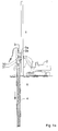
- Figure 1 is a schematic overview of the device and method in accordance with the present invention.
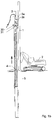
- Figure 2 is a schematic view of a typical lower mixing blade (the rotary head) of the mixing member of the device in accordance with the invention.
- Figures 3 - 6 are schematic representations of several possible mixed pile patterns.
- Figure 7 is a detailed schematic view of part of the mixing member and tube.
- the device illustrated by these figures was developed to render possible given works, as described in the opening paragraph of the present specification.
- a device which excellently satisfies the object aimed at is shown in Figure 1.
- the device comprises a supporting structure 1 which may be manipulated by for instance a caterpillar vehicle 2 (also known in the art as a drilling rig). Obviously any other manipulating structure, such as for instance a crane, may be used instead.
- a double bore head 3 is attached on the supporting structure 1.
- This double bore head 3 comprises two rotary driving engines 3a and 3b.
- Rotary engine 3b is able to rotationally drive a tube 5, while rotary engine 3a is able to rotationally drive mixing member 4.
- Rotary engines 3a and 3b may form a combined unit or may be two separate units.
- rotary engines 3a and 3b may be translatable - together or apart - along the supporting structure 1 along its longitudinal direction.
- Mixing member 4 and tube 5 are supported such that they extend substantially coaxially to each other, whereby mixing member 4 can be translated into tube 5. It is also possible to provide the mixing member 4 with a telescopic rod, thereby enabling to push mixing member 4 into the soil at a depth below the depth of the underside of tube 5. Mixing member 4 thereby protrudes further into the soil than tube 5.
- rotary driving engines 3a and 3b preferably drive the mixing member 4 and tube 5 in opposite directions when drilling into the soil layers.
- the lower end of the mixing member 4 (the end which protrudes first into the soil when drilling the hole) is formed by a shaft 11 which can be caused to rotate together with the rest of the mixing member, or of which, if so required, only the head, i.e. its lower portion, is capable of independent rotation.
- the bottom part of the shaft 11 is provided with at least one blade 12, which is intended for injecting a fluid at a high pressure.
- the apertures through which this fluid is injected at a high or a very high pressure are denoted by reference numerals 13.
- the arrows 14 indicate a possible direction in which the shaft 11 with blades 12 rotates.
- Two further elements 15 having apertures 13' are preferably attached to the blades 12.
- the binding agent to be mixed with the loosened soil may be added at a lower pressure (up to a maximum of preferably 50 bar) and is then mainly effected through apertures 13' in a direction opposite to the direction of rotation of the blades 12, which are primarily provided for cutting open the soil mass to be processed.
- the binding agent is consequently in this embodiment of the invention fed into a mass which has already been cut open and homogenized by injecting a fluid at a high pressure.
- the blades 12 and the coupling elements 15 coupled thereto are represented as being of a tubular shape.
- Tubular blades 12 and associated tubular elements 15 offer great advantages from a constructional point of view since the blades thus formed and elements connected thereto are excellent means for guiding the fluid employed together with the binding agent. This guidance can for instance also be accomplished by separate pipelines, extending inside of the tubular elements.
- the supply lines or feed pipes for the fluid and/or binding agent run through the mixing member over its entire length.
- Easy flow of fluid and/or hardenable binder can also be provided by using a hollow mixing member 4.
- the blades 12 may be formed by steel sections or small beams on which the required pipelines for injecting fluid and binding agent are fastened.
- the structure of said blades 12 is determined by their various functions. These functions can in essence be summarized as follows: a) cutting and mixing soil masses; b) injecting over adjustable distances various binding agent compositions; c) accommodating or supporting the pipelines for fluid and binding agents; d) constituting if so required the lines mentioned sub c).
- the length of the blades 12 taken in the direction from the wall of the rotary head depends of course on the objective.
- the overall length of the blades is between approximately 0,30m and 5 m, of course dependent on the diameter of the tube 5 used in the method, and the desired diameter of the mixed pile to be formed.
- the overall length of the blades is between approximately 0,40 m and 1,20 m.
- the blades 12 and/or 15 may be provided with mechanical cutting devices 24, to further aid ingression of the mixing member 4 into the soil layers.
- a reinforcement means 16 may be provided at the tip of the mixing member 4.
- This reinforcement means 16 may be of any shape and does not form a characterizing feature of the invention.
- the shaft 11 and mixing member 4 can rotate in two directions and at different speeds. It can also be moved up and down and this likewise at different speeds.
- the mixing member 4 and shaft 11 itself can be utilized as a tube in which the fluid feed-through channels can be incorporated.
- the shaft 11 itself can drive the blades but it will be obvious that the blades with the rotary head of the device may form a separate component part thereof.
- the mixing member 4, with optionally shaft 11, can be set at any angle by supporting member 1, which may be manipulated from a lifting platform or pontoon or from the landward side when the device is part of, for example, a vehicle.
- Mixing member 4 preferably is provided at its lowest end with a conically shaped protrusion for easy penetration into the soil layers. Moreover, mixing member 4 preferably is provided with apertures 6 for injecting fluid and/or hardenable binder under high pressure. These apertures 6 may be spaced along the longitudinal direction of the mixing member 4 over its entire length. It is even more preferred to provide the mixing blades 8 of mixing member 4 with apertures 7, which may be in the form of nozzles, adjustable with respect to the direction of injection of the fluid and/or hardenable binder.
- apertures 7 on blades 8, and apertures 13, 13' on blades 12 and associates tubular elements 15 are preferably arranged along the radial direction of mixing blades 8 and 12, and associates tubular elements 15.
- the radial direction is defined with respect to the longitudinal axis of the mixing member 4. More preferred this radial arrangement is such that the distance between following apertures becomes larger for apertures closer to the central axis of the mixing member 4. It is possible to provide the apertures with nozzles 7, 13 which may be positioned in a specific direction.
- Tube 5 consists essentially of a tubular structure preferably provided at its lower end with a cutting means.
- the cutting means may be any suitable cutting device known to the skilled person in order to aid to rotationally insert the tube into the subsoil structures.
- Tube 5 preferably has a substantially smooth outer surface, to be able to drive tube 5 into the soil easily.
- the circumferential wall of tube 5 may be perforated, i.e. be provided with irregularly and/or regularly spaced openings of some size.
- the inner side of the circumferential wall of tube 5 preferably is provided with additional mechanical mixing devices 19, such as elevated wall portions pointing radially inwards, which cooperate with the blades 8 and/or the fluid jets (6, 7) of mixing member 4.
- These wall portions 19 may extend over at least a part of the inner surface of tube 5, but may also be in the form of pins, and the like.
- FIGS 3 and 4 illustrate several patterns for the mixed piles 20.
- a triangular and a square grid pattern wherein a non-processed area remains between the piles 20 can easily be formed.
- Such patterns are for instance suitable to lay a foundation.
- Figure 5 shows processed soil layers of the so-called wall-type in which a non-processed area remains between rows of adjacently arranged piles 21. Piles 21 have been formed by drilling the tube of the second pile partly into the already formed first pile.
- Figure 6 illustrates soil layers which are processed over a larger area wherein a given area was "fully" processed and the plurality of piles 22 fully occupy the relevant area.
- the pile structures shown in figures 5 and 6 it will be noted that the built-up piles 21, 22 have fused together. This is of course possible because the binding agent used and injected here will harden only progressively and several contiguous piles have in fact, and partly, fused together. This type of arrangement is particularly suitable to form a water retaining wall, and is only possible by using the device and method of the invention. Indeed the outer tube allows to predetermine the diameter of the mixed piles formed by the method.
- Figure 7 shows by way of example a detail of the mixing member 4 provided with blades 8 and surrounded by tube 5.
- Mixing member 4 rotates in direction 14, while tube 5 rotates in the direction 14', opposite to direction 14.
- Blades 8 are optional and may be adapted to the nature of the soil into which mixing member 4 is applied. The skilled person may for instance vary the tilt angle of the blades 8 with respect to the longitudinal axis of the mixing member 4, the width and shape of the blades, the pitch of the blades, and so on. It is also possible to provide a mixing member 4 which is only over part of its surface provided with blades 8, such that the mixing member 4 is bladeless over a part of its length. It is also possible to provide the mixing member 4 with pins and other protruded parts 19, instead of, or in addition to the blades 8.
- the mixing member 4 may have a hollow core through which the binding agent which is suitable for the purpose of forming a mixed pile may be transported.
- Adding the binding agent can be performed in several ways: a) In the first place adding the binding agent can be effected via apertures 13' which are specially provided for this purpose and which allow the binding agent and a fluid, used as a vehicle of the binding agent, to pass at a lower pressure. Adding the binding agent at a lower pressure (up to a maximum of approximately 50 bar) is preferably performed in counter flow to the direction 14 in which the high-pressure jets 13 are active.
- the binding agent can be injected together with the high-pressure jets 13, 6, 7 into the material to be processed. Since the binding agent preferably requires a fluid in order to be easily conveyable, the binding agent is injected together with the fluid at a high pressure (between approximately 5 to 1000 bar).
- a plurality of mixed piles are formed in subsoil layers, by first drilling a hole into the soil layers. This is done by bringing the assembly of mixing member 4 and tube 5 in the vicinity of the location where a pile is to be formed through drilling rig 2. Drilling rig 2 then manipulates supporting structure 1 provided with mixing member 4, tube 5, bore heads 3a and 3b (or more bore heads if required) and any other additional devices such that the desired starting position is reached. In many circumstances, this position will be substantially vertical to the soil surface, although this is not required to carry out the invention. As illustrated in Figure 1 a, the assembly of mixing member 4 and tube 5 is driven into the subsoil by the action of bore heads 3a and 3b.
- the rotational directions of mixing member 4 and tube 5 are indicated in Figure 1 as 30 and 31.
- the soil inside the tube 5 is loosened by the action of the blades 8 and 12, and/or by the action of the fluid injected through nozzles 6, 7, and/or 13 and 13'.
- the binding agent fluid is contained in a reservoir, which is provided with a supply line to the mixing member 4 and/or tube 5. Intimate mixing between binding agent and soil material is obtained, thereby stabilizing the soil substantially inside the tube 5. and forming the mixed pile 20, 21 and/or 22.
- the rotational directions 30, 31 of mixing element 4 and tube 5 respectively are then reversed while preferably injecting binder.
- the assembly of mixing element 4 and tube 5 is hereby translated upward along supporting member 1.
- original soil is removed from the space substantially inside the tube 5, and replaced by a soil/binder mixture (a pile thus formed is denoted as a "mixed" pile).
- the formed mixed pile 20 may be reinforced further by introducing into it a suitable armament 23, such as for instance steel rods and the like. Providing the mixed pile with an additional reinforcement is optional and does not constitute a necessary requirement in the method according to the invention. Finally the mixed pile 20 is allowed to harden during a suitable period, before it will be loaded.
- the above method may be repeated several times, thus forming a plurality of mixed piles. Possible patterns for the mixed piles are illustrated in Figures 3 - 6.
Abstract
Description
- The invention relates to a method of forming a mixed pile in subsoil layers, comprising drilling a hole into the soil layers, loosening the soil inside the bore hole, and mixing said soil with a binding agent to stabilize it and form the mixed pile. The invention also relates to a device for performing the method.
- A known method of forming a mixed pile in subsoil layers is described in DE-A-10216952. In DE-A-10216952, a method is disclosed wherein a hole is formed in the subsoil layers by introducing an assembly of a tube and a rotationally driven mixing member into the subsoil layers. The mixing member in the form of a shaft extends substantially inside of and coaxially with said tube and is provided with a plurality of mixing blades, arranged along its longitudinal direction. During introduction into the subsoil, the rotating mixing member loosens up the soil inside the tube by the action of the mixing blades and removes said soil by transporting it to the surface. A hardenable binding agent is brought into the bored hole and mixed with the loosened soil by rotating the mixing member inside the tube. After thorough mixing of the binding agent and soil, the assembly is removed from the subsoil by pulling it upward. As a result of the known method, a mixed pile is formed in the subsoil layers, consisting of a hardened mixture of soil and binding agent. A plurality of mixed piles thus formed can for instance be used as foundation for aboveground constructions, to stabilize soils in general and/or to form an earth-retaining wall.
- Although the known method provides for suitable mixed piles, a huge amount of soil has to be removed from the subsoil and transported to the surface during the manufacture of the mixed pile. Moreover the mixing of hardenable binding agent and the soil inside the tube by rotating the mixing member is not efficient. As a result a large amount of binding agent has to be used in order to obtain the necessary structural rigidity for the mixed pile.
- It is the aim of the present invention to provide a method of forming a mixed pile in subsoil layers, comprising drilling a hole into the soil layers, loosening the soil inside the bore hole, and mixing said soil with a binding agent to stabilize it and form the mixed pile, whereby a limited amount of soil has to be removed during the manufacture of the mixed pile, and a limited amount of binding agent has to be supplied in order to obtain the necessary structural rigidity for the mixed pile.
- This aim and further advantages described below are obtained by a method according to the characterizing portion of
claim 1. In particular, the method according to the invention is characterized in that the soil inside the bore hole is loosened by the cutting action of high-pressure jets, whilst at least a hardening binding agent is added to the loosened materials and the whole is mixed by means of the mechanical action of the mixing blades of the mixing member and by the created turbulence of the high-pressure jets. - By loosening the soil substantially inside the tube through the action of high-pressure jets, a much improved mixing efficiency of binder and soil is achieved. The high-pressure jets effectively cut the soil inside the tube into small particles. These small particles are easily mixed with the hardenable binding agent to form a pile with the necessary rigidity after hardening out the mixture of soil and binder. As a result of the action of the high-pressure jets, applicant has surprisingly found that much less soil needs to be transported to the surface by the mixing member. Also it turned out that substantially less binding agent is necessary to obtain a pile with comparable structural rigidity as that of the pile, obtained by the known method.
- The method according to the invention can be applied in any soil material. It is for instance possible to use the method in silt, clay and/or organic materials, in sand, sandstone, gravel, masonry and reinforced or un-reinforced concrete materials, and/or allied materials.
- A field in which the method of the invention is applied, is inter alia producing stable foundation layers in said soil layers consisting of silt or technically equivalent materials. A further field of application is making such ground layers, banks etc. resistant to all forms of erosion. Another field of application is providing earth-retaining and/or water retaining walls, or underground walls able to retard the seeping in of groundwater.
- The method of the invention is preferably used in soils which contain layers of hard material, such as for instance rock and/or the remains of formations of old foundation elements. Because the method according to the invention employs a tube around the mixing member, the assembly of mixing member and tube effectively cuts through such layers of hard material, instead of being branched off by them. Also, the use of a tube makes it possible to provide mixed piles with a well defined, predetermined diameter. This allows to construct earth- and/or groundwater-retaining walls with much improved retaining capability, since it is now possible to accurately dimension the adjacent mixed piles, thus preventing accidental slits or openings between them.
- According to the method of the invention, high-pressure jets are used to loosen up the earth masses, eventually in combination with mechanical means provided by the mixing blades of the mixing member. Compared to the known method, the use of high-pressure jets to loosen up the soil (substantially) between mixing member and tube, and to mix said soil and binding agent entails several advantages: a) the required mechanical moment to rotate the mixing member during drilling into the ground is lower, which considerably reduces the required rotary power of the bore head; b) the supporting structures of the device used to perform the method of the invention can be executed comparatively lighter, which improves manoeuvrability of the device; and c) the wear rate of knives and mixing blades on the mixing member and possibly on the tube is much reduced since the cutting forces which in the normal method are very substantial, are lower.
- A characteristic feature of the method according to the invention is the use of a fluid to be injected at high pressure, which fluid readily allows to cut said soil materials, thereby disrupting the soil structure, allows to at least partly dislodge the disrupted particles, and finally allows to bind the soil particles again into a novel solid soil structure. Said fluid is preferably injected in accordance with a rotary pattern, whereby turbulences are created in order to better homogenize the soil and fluid materials.
- When applying the known method it frequently happens that large pieces of soil materials are entrained by the mixing blades of the mixing member. These pieces may interfere with the rotating action of the mixing member, or may inhibit the transport to the surface of the excavated soil material. An additional advantage of the method and device according to the invention is that the soil materials are effectively cut into small pieces, thus preventing such phenomenon.
- According to a preferred embodiment of the method of the invention, the hardenable binding agent is added to the loosened soil species in counter flow to the abovementioned rotary pattern.
- In accordance with a further preferred embodiment said hardenable binding agent is injected into the soil species by means of the high-pressure jets.
- In accordance with a still further preferred embodiment of the method the hardenable binding agent is simultaneously injected at a high pressure by means of said high-pressure jets and the binding agent is also injected at a, preferably lower pressure at any arbitrary angle to the loosened materials. In given circumstances it can be useful to provide also an injection of binding agent together with the high-pressure injection. This variant and further variants of the method are proof of its high degree of flexibility.
- Suitable binding agents for use in the method of the invention may for instance be selected from cement, bentonite, fly ash, lime, mortar, and derived cement types (known by the person skilled in the art as "blends") such as for instance Dämmer, gels, polymers, sand, flint chips and/or shingle, or a combination of said materials.
- The method in accordance with the invention and the device derived there from render it possible to process soil layers of widely different types to the desired depth, with the object to introduce mixed piles or foundations therein. The essential difference with the techniques which have been used in the art up till now resides in the fact that the soil material which has to be part of a formed mixed pile is cut, partly dislodged and partly mixed by injecting a fluid at a high pressure into the soil layers to be processed.
- High pressure must in the context of the present application be understood to mean a pressure between 5 and 1000 bar, more preferably between 200 and 800 bar, most preferably between 350 and 500 bar. The fluid to be injected at high pressure is preferably water or air, or more preferably a combination of both of them. To the fluid a hardenable binding agent is preferably added.
- Adopting a mixture of hardenable binding agent with either air and/or water as fluid to be injected, allows to inject the binding agent into the soil materials while simultaneously cutting and loosening up the soil materials. The injection of the fluid at a high pressure is preferably performed in accordance with a rotary pattern. (Part) of the binding agent is then preferably added, if necessary at a lower pressure in counter flow to the high-pressure injection. Adding (part) of the binding agent can also be effected, preferably also at a lower pressure, in the same (rotational) direction as the high-pressure injection.
- One of the most striking features of the method and the device of the invention is therefore that by primarily using the cutting force of the fluid injected at a high pressure, there must be no fear for rapid wear of cutting tools, and/or mixing blades. In addition, it will also be readily appreciated that the method shows great flexibility since the high and/or lower pressure at which fluid and/or binding agent are injected into the soil can be varied at will, dependent on for instance soil structure and characteristics. The fluid may, according to the invention be injected over the entire length of the mixing member. In a preferred embodiment of the method the mixing member extends further downward into the soil layers than the surrounding tube, and is moreover provided with injection apertures in this lower part of the mixing member. Hence, fluid is freely - not retained by the tube wall - injected into the soil layers over a radial distance which is larger than the diameter of the tube. The area influenced by the fluid injected at a high pressure can be adapted to the needs at any moment by selecting the pressure level. This embodiment is particularly useful when constructing a water impermeable wall of mixed piles. Indeed the method according to the invention readily allows to construct adjacent mixed piles which partly overlap, since the use of the tube allows to partly bore into an already formed mixed pile. In this way a plurality of piles may be formed which partly overlap and thereby form a water seepage retarding or water retaining wall. By injecting fluid with hardenable binding agent under high pressure radially outward from underneath the tube, a thorough mixing between an already formed mixed pile and a following - still to be formed pile - is obtained. This further improves the water retaining capability of the plurality of adjacently formed mixed piles.
- The invention also relates to a device for putting the method in accordance with the invention into effect. Further details of the device and method of the invention will be apparent from the following description of a preferred embodiment of the device. This description is only given by way of example and does not imply that the invention is limited in any way to the example. The reference numbers relate to the accompanying figures.
- Figure 1 is a schematic overview of the device and method in accordance with the present invention.
- Figure 2 is a schematic view of a typical lower mixing blade (the rotary head) of the mixing member of the device in accordance with the invention.
- Figures 3 - 6 are schematic representations of several possible mixed pile patterns.
- Figure 7 is a detailed schematic view of part of the mixing member and tube.
- The device illustrated by these figures was developed to render possible given works, as described in the opening paragraph of the present specification. A device which excellently satisfies the object aimed at, is shown in Figure 1. The device comprises a supporting
structure 1 which may be manipulated by for instance a caterpillar vehicle 2 (also known in the art as a drilling rig). Obviously any other manipulating structure, such as for instance a crane, may be used instead. On the supportingstructure 1, adouble bore head 3 is attached. Thisdouble bore head 3 comprises tworotary driving engines Rotary engine 3b is able to rotationally drive atube 5, whilerotary engine 3a is able to rotationally drive mixingmember 4.Rotary engines rotary engines structure 1 along its longitudinal direction. Mixingmember 4 andtube 5 are supported such that they extend substantially coaxially to each other, whereby mixingmember 4 can be translated intotube 5. It is also possible to provide the mixingmember 4 with a telescopic rod, thereby enabling to push mixingmember 4 into the soil at a depth below the depth of the underside oftube 5. Mixingmember 4 thereby protrudes further into the soil thantube 5. In the method according to the inventionrotary driving engines member 4 andtube 5 in opposite directions when drilling into the soil layers. By adopting opposite rotational directions for mixingmember 4 andtube 5 during drilling into the ground, the torsion forces experienced by thedouble bore head 3, and by the whole device, are substantially reduced during the drilling operation. Also, when hitting a subsoil layer with substantial hardness, the assembly of mixingmember 4 andtube 5 does not easily branch off. The lower end of the mixing member 4 (the end which protrudes first into the soil when drilling the hole) is formed by ashaft 11 which can be caused to rotate together with the rest of the mixing member, or of which, if so required, only the head, i.e. its lower portion, is capable of independent rotation. The bottom part of theshaft 11 is provided with at least oneblade 12, which is intended for injecting a fluid at a high pressure. The apertures through which this fluid is injected at a high or a very high pressure are denoted byreference numerals 13. Thearrows 14 indicate a possible direction in which theshaft 11 withblades 12 rotates. Twofurther elements 15 having apertures 13' are preferably attached to theblades 12. - In an embodiment according to the invention the binding agent to be mixed with the loosened soil may be added at a lower pressure (up to a maximum of preferably 50 bar) and is then mainly effected through apertures 13' in a direction opposite to the direction of rotation of the
blades 12, which are primarily provided for cutting open the soil mass to be processed. The binding agent is consequently in this embodiment of the invention fed into a mass which has already been cut open and homogenized by injecting a fluid at a high pressure. - In the figures added to the description, the
blades 12 and thecoupling elements 15 coupled thereto are represented as being of a tubular shape.Tubular blades 12 and associatedtubular elements 15 offer great advantages from a constructional point of view since the blades thus formed and elements connected thereto are excellent means for guiding the fluid employed together with the binding agent. This guidance can for instance also be accomplished by separate pipelines, extending inside of the tubular elements. - It is self-understood that the supply lines or feed pipes for the fluid and/or binding agent run through the mixing member over its entire length. Easy flow of fluid and/or hardenable binder can also be provided by using a
hollow mixing member 4. In a completely different embodiment theblades 12 may be formed by steel sections or small beams on which the required pipelines for injecting fluid and binding agent are fastened. - The structure of said
blades 12 is determined by their various functions. These functions can in essence be summarized as follows: a) cutting and mixing soil masses; b) injecting over adjustable distances various binding agent compositions; c) accommodating or supporting the pipelines for fluid and binding agents; d) constituting if so required the lines mentioned sub c). - The length of the
blades 12 taken in the direction from the wall of the rotary head depends of course on the objective. In practice the overall length of the blades is between approximately 0,30m and 5 m, of course dependent on the diameter of thetube 5 used in the method, and the desired diameter of the mixed pile to be formed. Preferably the overall length of the blades is between approximately 0,40 m and 1,20 m. - As shown in Figure 7, the
blades 12 and/or 15 may be provided withmechanical cutting devices 24, to further aid ingression of the mixingmember 4 into the soil layers. - From a constructional point of view, as is shown in Figure 2, a reinforcement means 16 may be provided at the tip of the mixing
member 4. This reinforcement means 16 may be of any shape and does not form a characterizing feature of the invention. Theshaft 11 and mixingmember 4, can rotate in two directions and at different speeds. It can also be moved up and down and this likewise at different speeds. The mixingmember 4 andshaft 11 itself can be utilized as a tube in which the fluid feed-through channels can be incorporated. Theshaft 11 itself can drive the blades but it will be obvious that the blades with the rotary head of the device may form a separate component part thereof. - Although in the application reference is made in several places to a rotary head, the technical equivalent thereof is a shaft which rotates through its overall length. The choice of the suitable device does in no way detract from the principle of the invention.
- Relative to the soil surface the mixing
member 4, withoptionally shaft 11, can be set at any angle by supportingmember 1, which may be manipulated from a lifting platform or pontoon or from the landward side when the device is part of, for example, a vehicle. - Mixing
member 4 preferably is provided at its lowest end with a conically shaped protrusion for easy penetration into the soil layers. Moreover, mixingmember 4 preferably is provided withapertures 6 for injecting fluid and/or hardenable binder under high pressure. Theseapertures 6 may be spaced along the longitudinal direction of the mixingmember 4 over its entire length. It is even more preferred to provide themixing blades 8 of mixingmember 4 with apertures 7, which may be in the form of nozzles, adjustable with respect to the direction of injection of the fluid and/or hardenable binder. To obtain the desired homogeneous mixing of soil particles and binder, apertures 7 onblades 8, andapertures 13, 13' onblades 12 and associates tubularelements 15 are preferably arranged along the radial direction of mixingblades tubular elements 15. The radial direction is defined with respect to the longitudinal axis of the mixingmember 4. More preferred this radial arrangement is such that the distance between following apertures becomes larger for apertures closer to the central axis of the mixingmember 4. It is possible to provide the apertures withnozzles 7, 13 which may be positioned in a specific direction. -
Tube 5 consists essentially of a tubular structure preferably provided at its lower end with a cutting means. The cutting means may be any suitable cutting device known to the skilled person in order to aid to rotationally insert the tube into the subsoil structures.Tube 5 preferably has a substantially smooth outer surface, to be able to drivetube 5 into the soil easily. However, the circumferential wall oftube 5 may be perforated, i.e. be provided with irregularly and/or regularly spaced openings of some size. To further improve the efficiency of the method and device, the inner side of the circumferential wall oftube 5 preferably is provided with additionalmechanical mixing devices 19, such as elevated wall portions pointing radially inwards, which cooperate with theblades 8 and/or the fluid jets (6, 7) of mixingmember 4. Thesewall portions 19 may extend over at least a part of the inner surface oftube 5, but may also be in the form of pins, and the like. - When the soil layers must be stabilized to a given depth and a supporting structure must be erected therein or thereupon, inter alia for the subsequent erection of, for example, an embankment, operations can be effected in accordance with several patterns. Figures 3 and 4 illustrate several patterns for the
mixed piles 20. According to the invention a triangular and a square grid pattern wherein a non-processed area remains between thepiles 20 can easily be formed. Such patterns are for instance suitable to lay a foundation. - Figure 5 shows processed soil layers of the so-called wall-type in which a non-processed area remains between rows of adjacently arranged piles 21.
Piles 21 have been formed by drilling the tube of the second pile partly into the already formed first pile. - Figure 6 illustrates soil layers which are processed over a larger area wherein a given area was "fully" processed and the plurality of
piles 22 fully occupy the relevant area. As regards the pile structures shown in figures 5 and 6, it will be noted that the built-uppiles - Figure 7 shows by way of example a detail of the mixing
member 4 provided withblades 8 and surrounded bytube 5. Mixingmember 4 rotates indirection 14, whiletube 5 rotates in the direction 14', opposite todirection 14.Blades 8 are optional and may be adapted to the nature of the soil into which mixingmember 4 is applied. The skilled person may for instance vary the tilt angle of theblades 8 with respect to the longitudinal axis of the mixingmember 4, the width and shape of the blades, the pitch of the blades, and so on. It is also possible to provide a mixingmember 4 which is only over part of its surface provided withblades 8, such that the mixingmember 4 is bladeless over a part of its length. It is also possible to provide the mixingmember 4 with pins and other protrudedparts 19, instead of, or in addition to theblades 8. - The mixing
member 4 may have a hollow core through which the binding agent which is suitable for the purpose of forming a mixed pile may be transported. Adding the binding agent can be performed in several ways: a) In the first place adding the binding agent can be effected via apertures 13' which are specially provided for this purpose and which allow the binding agent and a fluid, used as a vehicle of the binding agent, to pass at a lower pressure. Adding the binding agent at a lower pressure (up to a maximum of approximately 50 bar) is preferably performed in counter flow to thedirection 14 in which the high-pressure jets 13 are active. The low pressure is sufficient to pass and distribute the fluid and the transported binding agent in the opened-up materials; b) In certain cases, and as a function of the stabilization to be performed, the binding agent can be injected together with the high-pressure jets - According to the invention a plurality of mixed piles are formed in subsoil layers, by first drilling a hole into the soil layers. This is done by bringing the assembly of mixing
member 4 andtube 5 in the vicinity of the location where a pile is to be formed throughdrilling rig 2.Drilling rig 2 then manipulates supportingstructure 1 provided with mixingmember 4,tube 5, bore heads 3a and 3b (or more bore heads if required) and any other additional devices such that the desired starting position is reached. In many circumstances, this position will be substantially vertical to the soil surface, although this is not required to carry out the invention. As illustrated in Figure 1 a, the assembly of mixingmember 4 andtube 5 is driven into the subsoil by the action of bore heads 3a and 3b. The rotational directions of mixingmember 4 andtube 5 are indicated in Figure 1 as 30 and 31. By rotatingtube 5 and mixinghead 4 in counter rotation to each other hard subsoil layers are easily cut through. During this phase of the method according to this embodiment, the soil inside thetube 5 is loosened by the action of theblades nozzles 6, 7, and/or 13 and 13'. Obviously the binding agent fluid is contained in a reservoir, which is provided with a supply line to the mixingmember 4 and/ortube 5. Intimate mixing between binding agent and soil material is obtained, thereby stabilizing the soil substantially inside thetube 5. and forming themixed pile rotational directions element 4 andtube 5 respectively are then reversed while preferably injecting binder. The assembly of mixingelement 4 andtube 5 is hereby translated upward along supportingmember 1. In this way original soil is removed from the space substantially inside thetube 5, and replaced by a soil/binder mixture (a pile thus formed is denoted as a "mixed" pile). In a third phase the formedmixed pile 20 may be reinforced further by introducing into it asuitable armament 23, such as for instance steel rods and the like. Providing the mixed pile with an additional reinforcement is optional and does not constitute a necessary requirement in the method according to the invention. Finally themixed pile 20 is allowed to harden during a suitable period, before it will be loaded. - The above method may be repeated several times, thus forming a plurality of mixed piles. Possible patterns for the mixed piles are illustrated in Figures 3 - 6.
- The invention is not limited to the embodiment described herein and many modifications may be made, in so far as these modifications are within the scope of the accompanying claims.
Claims (19)
- A method of forming a mixed pile in subsoil layers, comprising drilling a hole into the soil layers, loosening the soil and mixing the soil inside the bore hole with a binding agent to stabilize said soil and form the mixed pile, wherein the hole is formed by introducing an assembly of a tube and a rotationally driven mixing member into the subsoil layers, said mixing member extending substantially inside of and coaxially with said tube and being provided with a plurality of mixing blades, wherein the binding agent is injected into and mixed with the soil, wherein the assembly is removed by pulling it upward, characterized in that, the soil to be stabilized is loosened by the cutting action of high-pressure jets, whilst at least a binding agent is added to the loosened materials and the whole is mixed by means of the mechanical action of the blades and by the created turbulence of the high-pressure jets.
- A method as claimed in claim 1, characterized in that said binding agent is added at a, preferably lower pressure to the soil loosened by the said high pressure jets, and in counter flow to said high-pressure jets.
- A method as claimed in claim 1 or 2, characterized in that said binding agent is injected in the soil to be loosened by employing said high-pressure jets.
- A method as claimed in claim 2 or 3, characterized in that said binding agent is simultaneously injected at a high pressure by using said high-pressure jets and, in counter flow thereto, is added at a lower pressure to the loosened materials.
- A method as claimed in any one of claims 1 - 3, characterized in that the properties of the fluid used in the high pressure jets are such as to readily allow to cut said soil materials, thereby disrupting the soil structure, allow to at least partly dislodge the disrupted particles, and finally allow to bind the soil particles again into a novel solid soil structure, and that said fluid is injected in accordance with a rotary pattern, whereby turbulences are created in order to better homogenize the soil and fluid materials.
- A method as claimed in any one of claims 1 - 5, characterized in that said soil materials are loosened by employing high pressure jets at a pressure of between 5 and 1000 bar.
- A method as claimed in claim 2 or 4, characterized in that said lower pressure is selected between 1 bar and 50 bar.
- A method as claimed in any one of claims 1 - 7, characterized in that the fluid used in the high pressure jets comprises water and/or air.
- A method as claimed in claim 8, characterized in that said binding agent is injected together with said fluid.
- A method as claimed in any one of claims 1 - 9, characterized in that the binding agent comprises at least one of cement, bentonite, fly ash, lime, polymers, mortar, derived cement types, gels, or a combination thereof.
- A device for forming a mixed pile in subsoil layers comprising an assembly of a tube 5 and a mixing member 4, which assembly can be manipulated by the action of a manipulating device 1 and bored into the subsoil by the action of bore head 3, which mixing member 4 extends substantially inside of and coaxially with said tube 5 and is provided with a plurality of mixing blades 7, characterized in that mixing member 4 contains at least over part of its surface a plurality of apertures 13 through which a fluid can be injected under high pressure into the soil.
- A device according to claim 11, characterized in that the apertures 13 are located on the mixing blades 7.
- A device according to claim 11 or 12, characterized in that the apertures 13 are located predominantly at the lower end of the mixing member 4.
- A device according to claim 13, characterized in that, the mixing member 4 at least at its lower end is provided with a rotary head 10 equipped with blades 12 for on the one hand injecting under pressure a fluid for loosening the materials, and on the other hand for adding at a lower pressure in counter flow thereto a binding agent to the loosened materials.
- A device as claimed in claim 13 or 14, characterized in that blades 12 have an overall length of between approximately 0,3 and approximately 5 m.
- A device as claimed in any one of claims 13 - 15, characterized in that blades 12 are of a tubular shape and have apertures 13 for injecting at a high pressure a fluid and/or a binding agent.
- A device as claimed in any one of claims 13 - 15, characterized in that blades 12 are constituted by sections to which pipelines for injecting a fluid at a high and/or at a low pressure, and/or a binding agent, are attached.
- A device as claimed in any one of claims 13 -16, characterized in that connected to each of tubular blades 12 there is a tubular element 15 for injecting through apertures 13' a fluid with a binding agent at a lower pressure and in counter flow to the high-pressure injection.
- A device as claimed in any one of claims 13 -18, characterized in that said rotary head is provided with reinforcing means 16.
Priority Applications (4)
| Application Number | Priority Date | Filing Date | Title |
|---|---|---|---|
| EP04447134A EP1600560B1 (en) | 2004-05-28 | 2004-05-28 | A method and device for forming a pile |
| AT04447134T ATE452246T1 (en) | 2004-05-28 | 2004-05-28 | METHOD AND APPARATUS FOR PRODUCING A PILE |
| DE602004024653T DE602004024653D1 (en) | 2004-05-28 | 2004-05-28 | Method and apparatus for producing a pile |
| PL04447134T PL1600560T3 (en) | 2004-05-28 | 2004-05-28 | A method and device for forming a pile |
Applications Claiming Priority (1)
| Application Number | Priority Date | Filing Date | Title |
|---|---|---|---|
| EP04447134A EP1600560B1 (en) | 2004-05-28 | 2004-05-28 | A method and device for forming a pile |
Publications (2)
| Publication Number | Publication Date |
|---|---|
| EP1600560A1 true EP1600560A1 (en) | 2005-11-30 |
| EP1600560B1 EP1600560B1 (en) | 2009-12-16 |
Family
ID=34933045
Family Applications (1)
| Application Number | Title | Priority Date | Filing Date |
|---|---|---|---|
| EP04447134A Active EP1600560B1 (en) | 2004-05-28 | 2004-05-28 | A method and device for forming a pile |
Country Status (4)
| Country | Link |
|---|---|
| EP (1) | EP1600560B1 (en) |
| AT (1) | ATE452246T1 (en) |
| DE (1) | DE602004024653D1 (en) |
| PL (1) | PL1600560T3 (en) |
Cited By (9)
| Publication number | Priority date | Publication date | Assignee | Title |
|---|---|---|---|---|
| CN100567193C (en) * | 2008-03-11 | 2009-12-09 | 天津市建筑科学研究院 | The method of lime, flyash premculded pile and pile-formation process and formation composite foundation |
| CN104674800A (en) * | 2014-12-31 | 2015-06-03 | 云南建工基础工程有限责任公司 | Method for forming high pressure jet grouting piles in peaty soil by using compounded curing agents |
| CN105254223A (en) * | 2015-09-01 | 2016-01-20 | 河北大地建设科技有限公司 | Compaction soil-cement-fly ash pile |
| CN106906709A (en) * | 2017-03-27 | 2017-06-30 | 石家庄铁道大学 | A kind of construction method of the modified cement earth pile of quick lime |
| JP2018021324A (en) * | 2016-08-02 | 2018-02-08 | 株式会社安藤・間 | Contaminated soil purification method, and partition wall body |
| JP2019065481A (en) * | 2017-09-28 | 2019-04-25 | 積水ハウス株式会社 | Soil improvement body and soil improvement body construction method |
| EP3361040B1 (en) * | 2017-02-13 | 2019-11-27 | BAUER Maschinen GmbH | Soil processing tool and method for creating a hole in the soil |
| JP2020143575A (en) * | 2016-08-02 | 2020-09-10 | 株式会社安藤・間 | Contaminated soil purification method |
| WO2022057437A1 (en) * | 2020-09-15 | 2022-03-24 | 上海强劲地基工程股份有限公司 | Stirring pile construction apparatus provided with stirring cage |
Families Citing this family (1)
| Publication number | Priority date | Publication date | Assignee | Title |
|---|---|---|---|---|
| CN108798527B (en) * | 2017-04-27 | 2023-07-18 | 上海工程机械厂有限公司 | Composite drilling tool |
Citations (5)
| Publication number | Priority date | Publication date | Assignee | Title |
|---|---|---|---|---|
| DE3831547A1 (en) * | 1988-09-16 | 1990-03-22 | Bauer Spezialtiefbau | Method of constructing a mortar column in the earth |
| JP2000273864A (en) * | 1999-03-23 | 2000-10-03 | Nkk Corp | Work execution method for screw pile |
| EP1045073A1 (en) * | 1999-04-15 | 2000-10-18 | TREVI S.p.A. | An excavation tool and a method for forming a column of consolidated soil |
| DE10216952A1 (en) | 2002-03-26 | 2003-10-23 | Harald Gollwitzer Gmbh | Construction method for a mixed pile in the ground uses driven mixer worm with outer tubing in bore hole to mix excavated material with binding agent for reproducible quality |
| JP2004137670A (en) * | 2002-10-15 | 2004-05-13 | Geotop Corp | Construction method for foundation pile and apparatus for it |
-
2004
- 2004-05-28 EP EP04447134A patent/EP1600560B1/en active Active
- 2004-05-28 PL PL04447134T patent/PL1600560T3/en unknown
- 2004-05-28 AT AT04447134T patent/ATE452246T1/en not_active IP Right Cessation
- 2004-05-28 DE DE602004024653T patent/DE602004024653D1/en active Active
Patent Citations (5)
| Publication number | Priority date | Publication date | Assignee | Title |
|---|---|---|---|---|
| DE3831547A1 (en) * | 1988-09-16 | 1990-03-22 | Bauer Spezialtiefbau | Method of constructing a mortar column in the earth |
| JP2000273864A (en) * | 1999-03-23 | 2000-10-03 | Nkk Corp | Work execution method for screw pile |
| EP1045073A1 (en) * | 1999-04-15 | 2000-10-18 | TREVI S.p.A. | An excavation tool and a method for forming a column of consolidated soil |
| DE10216952A1 (en) | 2002-03-26 | 2003-10-23 | Harald Gollwitzer Gmbh | Construction method for a mixed pile in the ground uses driven mixer worm with outer tubing in bore hole to mix excavated material with binding agent for reproducible quality |
| JP2004137670A (en) * | 2002-10-15 | 2004-05-13 | Geotop Corp | Construction method for foundation pile and apparatus for it |
Non-Patent Citations (3)
| Title |
|---|
| PATENT ABSTRACTS OF JAPAN vol. 1997, no. 07 31 July 1997 (1997-07-31) * |
| PATENT ABSTRACTS OF JAPAN vol. 2000, no. 13 5 February 2001 (2001-02-05) * |
| PATENT ABSTRACTS OF JAPAN vol. 2003, no. 12 5 December 2003 (2003-12-05) * |
Cited By (10)
| Publication number | Priority date | Publication date | Assignee | Title |
|---|---|---|---|---|
| CN100567193C (en) * | 2008-03-11 | 2009-12-09 | 天津市建筑科学研究院 | The method of lime, flyash premculded pile and pile-formation process and formation composite foundation |
| CN104674800A (en) * | 2014-12-31 | 2015-06-03 | 云南建工基础工程有限责任公司 | Method for forming high pressure jet grouting piles in peaty soil by using compounded curing agents |
| CN105254223A (en) * | 2015-09-01 | 2016-01-20 | 河北大地建设科技有限公司 | Compaction soil-cement-fly ash pile |
| JP2018021324A (en) * | 2016-08-02 | 2018-02-08 | 株式会社安藤・間 | Contaminated soil purification method, and partition wall body |
| JP2020143575A (en) * | 2016-08-02 | 2020-09-10 | 株式会社安藤・間 | Contaminated soil purification method |
| EP3361040B1 (en) * | 2017-02-13 | 2019-11-27 | BAUER Maschinen GmbH | Soil processing tool and method for creating a hole in the soil |
| CN106906709A (en) * | 2017-03-27 | 2017-06-30 | 石家庄铁道大学 | A kind of construction method of the modified cement earth pile of quick lime |
| CN106906709B (en) * | 2017-03-27 | 2020-02-14 | 石家庄铁道大学 | Construction method of quicklime modified cement soil pile |
| JP2019065481A (en) * | 2017-09-28 | 2019-04-25 | 積水ハウス株式会社 | Soil improvement body and soil improvement body construction method |
| WO2022057437A1 (en) * | 2020-09-15 | 2022-03-24 | 上海强劲地基工程股份有限公司 | Stirring pile construction apparatus provided with stirring cage |
Also Published As
| Publication number | Publication date |
|---|---|
| PL1600560T3 (en) | 2010-05-31 |
| ATE452246T1 (en) | 2010-01-15 |
| DE602004024653D1 (en) | 2010-01-28 |
| EP1600560B1 (en) | 2009-12-16 |
Similar Documents
| Publication | Publication Date | Title |
|---|---|---|
| JP4769878B2 (en) | Field pile with consistent properties from top to bottom and minimal voids | |
| EP1600560B1 (en) | A method and device for forming a pile | |
| JP4520913B2 (en) | Ground improvement method and existing structure foundation reinforcement method | |
| KR102070299B1 (en) | Construction apparatus of Cylindrical type pile and Construction apparatus of Taper type pile and Construction method of Taper type pile | |
| JP4679705B2 (en) | Equipment for constructing mechanically stirred air cement milk mixed pressure feeding method | |
| US6241426B1 (en) | Method for forming an interconnected underground structure | |
| JPS5985028A (en) | Steel pipe pile and laying work thereof | |
| KR100719875B1 (en) | Structure and construction method of cut-off wall using jet grouting | |
| KR20110079475A (en) | Apparatus for constructing pile using spray type excavating bit | |
| JP5075090B2 (en) | Cast-in-place pile construction method and cast-in-place pile | |
| CN107740419A (en) | Foundation pit supporting method and raked pile | |
| CN1504613A (en) | Forming method for water-proof pile fender and screw drill therefor | |
| JP5281213B1 (en) | Core material and soil cement continuous wall method using the same | |
| KR100573083B1 (en) | The bottom of the sea foundation improvement method air-hammer make use of adhesion excavator | |
| US11788249B2 (en) | Cutting tool adapter and method of underpinning structures using cutting tool adapter for soil mixing | |
| JP4074198B2 (en) | How to remove existing piles | |
| JP5284168B2 (en) | Excavation member for earth retaining member construction and earth retaining member construction method | |
| JPH0656015B2 (en) | Pile inside digging method | |
| JP2505976B2 (en) | How to create an underground structure | |
| KR100507983B1 (en) | Method for piling sheet in the base rock | |
| KR102517030B1 (en) | Construction Apparatus of Pile for Mortar-Injecting Type | |
| JPH0470422A (en) | Open caisson method | |
| WO2000044994A1 (en) | Soil mixing process | |
| JP2006037491A (en) | Expanded head pile and construction method of expanded head pile | |
| KR900005913B1 (en) | Base stake inflated in bump state at lower end there of and its construction |
Legal Events
| Date | Code | Title | Description |
|---|---|---|---|
| PUAI | Public reference made under article 153(3) epc to a published international application that has entered the european phase |
Free format text: ORIGINAL CODE: 0009012 |
|
| AK | Designated contracting states |
Kind code of ref document: A1 Designated state(s): AT BE BG CH CY CZ DE DK EE ES FI FR GB GR HU IE IT LI LU MC NL PL PT RO SE SI SK TR |
|
| AX | Request for extension of the european patent |
Extension state: AL HR LT LV MK |
|
| 17P | Request for examination filed |
Effective date: 20060523 |
|
| AKX | Designation fees paid |
Designated state(s): AT BE BG CH CY CZ DE DK EE ES FI FR GB GR HU IE IT LI LU MC NL PL PT RO SE SI SK TR |
|
| 17Q | First examination report despatched |
Effective date: 20080219 |
|
| GRAP | Despatch of communication of intention to grant a patent |
Free format text: ORIGINAL CODE: EPIDOSNIGR1 |
|
| GRAS | Grant fee paid |
Free format text: ORIGINAL CODE: EPIDOSNIGR3 |
|
| GRAA | (expected) grant |
Free format text: ORIGINAL CODE: 0009210 |
|
| AK | Designated contracting states |
Kind code of ref document: B1 Designated state(s): AT BE BG CH CY CZ DE DK EE ES FI FR GB GR HU IE IT LI LU MC NL PL PT RO SE SI SK TR |
|
| REG | Reference to a national code |
Ref country code: GB Ref legal event code: FG4D |
|
| REG | Reference to a national code |
Ref country code: CH Ref legal event code: EP |
|
| REG | Reference to a national code |
Ref country code: IE Ref legal event code: FG4D |
|
| REF | Corresponds to: |
Ref document number: 602004024653 Country of ref document: DE Date of ref document: 20100128 Kind code of ref document: P |
|
| REG | Reference to a national code |
Ref country code: NL Ref legal event code: T3 |
|
| PG25 | Lapsed in a contracting state [announced via postgrant information from national office to epo] |
Ref country code: SE Free format text: LAPSE BECAUSE OF FAILURE TO SUBMIT A TRANSLATION OF THE DESCRIPTION OR TO PAY THE FEE WITHIN THE PRESCRIBED TIME-LIMIT Effective date: 20091216 Ref country code: FI Free format text: LAPSE BECAUSE OF FAILURE TO SUBMIT A TRANSLATION OF THE DESCRIPTION OR TO PAY THE FEE WITHIN THE PRESCRIBED TIME-LIMIT Effective date: 20091216 |
|
| PG25 | Lapsed in a contracting state [announced via postgrant information from national office to epo] |
Ref country code: SI Free format text: LAPSE BECAUSE OF FAILURE TO SUBMIT A TRANSLATION OF THE DESCRIPTION OR TO PAY THE FEE WITHIN THE PRESCRIBED TIME-LIMIT Effective date: 20091216 |
|
| REG | Reference to a national code |
Ref country code: PL Ref legal event code: T3 |
|
| PG25 | Lapsed in a contracting state [announced via postgrant information from national office to epo] |
Ref country code: AT Free format text: LAPSE BECAUSE OF FAILURE TO SUBMIT A TRANSLATION OF THE DESCRIPTION OR TO PAY THE FEE WITHIN THE PRESCRIBED TIME-LIMIT Effective date: 20091216 |
|
| PG25 | Lapsed in a contracting state [announced via postgrant information from national office to epo] |
Ref country code: BG Free format text: LAPSE BECAUSE OF FAILURE TO SUBMIT A TRANSLATION OF THE DESCRIPTION OR TO PAY THE FEE WITHIN THE PRESCRIBED TIME-LIMIT Effective date: 20100316 Ref country code: EE Free format text: LAPSE BECAUSE OF FAILURE TO SUBMIT A TRANSLATION OF THE DESCRIPTION OR TO PAY THE FEE WITHIN THE PRESCRIBED TIME-LIMIT Effective date: 20091216 Ref country code: PT Free format text: LAPSE BECAUSE OF FAILURE TO SUBMIT A TRANSLATION OF THE DESCRIPTION OR TO PAY THE FEE WITHIN THE PRESCRIBED TIME-LIMIT Effective date: 20100416 Ref country code: ES Free format text: LAPSE BECAUSE OF FAILURE TO SUBMIT A TRANSLATION OF THE DESCRIPTION OR TO PAY THE FEE WITHIN THE PRESCRIBED TIME-LIMIT Effective date: 20100327 Ref country code: RO Free format text: LAPSE BECAUSE OF FAILURE TO SUBMIT A TRANSLATION OF THE DESCRIPTION OR TO PAY THE FEE WITHIN THE PRESCRIBED TIME-LIMIT Effective date: 20091216 |
|
| PG25 | Lapsed in a contracting state [announced via postgrant information from national office to epo] |
Ref country code: CZ Free format text: LAPSE BECAUSE OF FAILURE TO SUBMIT A TRANSLATION OF THE DESCRIPTION OR TO PAY THE FEE WITHIN THE PRESCRIBED TIME-LIMIT Effective date: 20091216 Ref country code: SK Free format text: LAPSE BECAUSE OF FAILURE TO SUBMIT A TRANSLATION OF THE DESCRIPTION OR TO PAY THE FEE WITHIN THE PRESCRIBED TIME-LIMIT Effective date: 20091216 |
|
| PLBE | No opposition filed within time limit |
Free format text: ORIGINAL CODE: 0009261 |
|
| STAA | Information on the status of an ep patent application or granted ep patent |
Free format text: STATUS: NO OPPOSITION FILED WITHIN TIME LIMIT |
|
| PG25 | Lapsed in a contracting state [announced via postgrant information from national office to epo] |
Ref country code: GR Free format text: LAPSE BECAUSE OF FAILURE TO SUBMIT A TRANSLATION OF THE DESCRIPTION OR TO PAY THE FEE WITHIN THE PRESCRIBED TIME-LIMIT Effective date: 20100317 Ref country code: CY Free format text: LAPSE BECAUSE OF FAILURE TO SUBMIT A TRANSLATION OF THE DESCRIPTION OR TO PAY THE FEE WITHIN THE PRESCRIBED TIME-LIMIT Effective date: 20091216 |
|
| 26N | No opposition filed |
Effective date: 20100917 |
|
| PG25 | Lapsed in a contracting state [announced via postgrant information from national office to epo] |
Ref country code: MC Free format text: LAPSE BECAUSE OF NON-PAYMENT OF DUE FEES Effective date: 20100531 |
|
| REG | Reference to a national code |
Ref country code: CH Ref legal event code: PL |
|
| PG25 | Lapsed in a contracting state [announced via postgrant information from national office to epo] |
Ref country code: DK Free format text: LAPSE BECAUSE OF FAILURE TO SUBMIT A TRANSLATION OF THE DESCRIPTION OR TO PAY THE FEE WITHIN THE PRESCRIBED TIME-LIMIT Effective date: 20091216 |
|
| PG25 | Lapsed in a contracting state [announced via postgrant information from national office to epo] |
Ref country code: CH Free format text: LAPSE BECAUSE OF NON-PAYMENT OF DUE FEES Effective date: 20100531 Ref country code: LI Free format text: LAPSE BECAUSE OF NON-PAYMENT OF DUE FEES Effective date: 20100531 |
|
| PG25 | Lapsed in a contracting state [announced via postgrant information from national office to epo] |
Ref country code: IT Free format text: LAPSE BECAUSE OF FAILURE TO SUBMIT A TRANSLATION OF THE DESCRIPTION OR TO PAY THE FEE WITHIN THE PRESCRIBED TIME-LIMIT Effective date: 20091216 |
|
| PG25 | Lapsed in a contracting state [announced via postgrant information from national office to epo] |
Ref country code: IE Free format text: LAPSE BECAUSE OF NON-PAYMENT OF DUE FEES Effective date: 20100528 |
|
| PG25 | Lapsed in a contracting state [announced via postgrant information from national office to epo] |
Ref country code: HU Free format text: LAPSE BECAUSE OF FAILURE TO SUBMIT A TRANSLATION OF THE DESCRIPTION OR TO PAY THE FEE WITHIN THE PRESCRIBED TIME-LIMIT Effective date: 20100617 |
|
| PG25 | Lapsed in a contracting state [announced via postgrant information from national office to epo] |
Ref country code: TR Free format text: LAPSE BECAUSE OF FAILURE TO SUBMIT A TRANSLATION OF THE DESCRIPTION OR TO PAY THE FEE WITHIN THE PRESCRIBED TIME-LIMIT Effective date: 20091216 |
|
| PGFP | Annual fee paid to national office [announced via postgrant information from national office to epo] |
Ref country code: FR Payment date: 20130410 Year of fee payment: 10 |
|
| PGFP | Annual fee paid to national office [announced via postgrant information from national office to epo] |
Ref country code: GB Payment date: 20130521 Year of fee payment: 10 |
|
| PGFP | Annual fee paid to national office [announced via postgrant information from national office to epo] |
Ref country code: PL Payment date: 20130423 Year of fee payment: 10 |
|
| GBPC | Gb: european patent ceased through non-payment of renewal fee |
Effective date: 20140528 |
|
| REG | Reference to a national code |
Ref country code: FR Ref legal event code: ST Effective date: 20150130 |
|
| PG25 | Lapsed in a contracting state [announced via postgrant information from national office to epo] |
Ref country code: FR Free format text: LAPSE BECAUSE OF NON-PAYMENT OF DUE FEES Effective date: 20140602 Ref country code: GB Free format text: LAPSE BECAUSE OF NON-PAYMENT OF DUE FEES Effective date: 20140528 |
|
| PG25 | Lapsed in a contracting state [announced via postgrant information from national office to epo] |
Ref country code: PL Free format text: LAPSE BECAUSE OF NON-PAYMENT OF DUE FEES Effective date: 20140528 |
|
| REG | Reference to a national code |
Ref country code: PL Ref legal event code: LAPE |
|
| PGFP | Annual fee paid to national office [announced via postgrant information from national office to epo] |
Ref country code: LU Payment date: 20160610 Year of fee payment: 13 |
|
| PG25 | Lapsed in a contracting state [announced via postgrant information from national office to epo] |
Ref country code: LU Free format text: LAPSE BECAUSE OF NON-PAYMENT OF DUE FEES Effective date: 20170531 |
|
| PG25 | Lapsed in a contracting state [announced via postgrant information from national office to epo] |
Ref country code: LU Free format text: LAPSE BECAUSE OF NON-PAYMENT OF DUE FEES Effective date: 20170528 |
|
| PGFP | Annual fee paid to national office [announced via postgrant information from national office to epo] |
Ref country code: NL Payment date: 20230412 Year of fee payment: 20 |
|
| PGFP | Annual fee paid to national office [announced via postgrant information from national office to epo] |
Ref country code: DE Payment date: 20230530 Year of fee payment: 20 |
|
| PGFP | Annual fee paid to national office [announced via postgrant information from national office to epo] |
Ref country code: BE Payment date: 20230412 Year of fee payment: 20 |