EP1600235A2 - Kettensäge für Gestein - Google Patents
Kettensäge für Gestein Download PDFInfo
- Publication number
- EP1600235A2 EP1600235A2 EP05011420A EP05011420A EP1600235A2 EP 1600235 A2 EP1600235 A2 EP 1600235A2 EP 05011420 A EP05011420 A EP 05011420A EP 05011420 A EP05011420 A EP 05011420A EP 1600235 A2 EP1600235 A2 EP 1600235A2
- Authority
- EP
- European Patent Office
- Prior art keywords
- cutting
- blade
- chain
- cutting tip
- links
- Prior art date
- Legal status (The legal status is an assumption and is not a legal conclusion. Google has not performed a legal analysis and makes no representation as to the accuracy of the status listed.)
- Withdrawn
Links
Images


Classifications
-
- B—PERFORMING OPERATIONS; TRANSPORTING
- B28—WORKING CEMENT, CLAY, OR STONE
- B28D—WORKING STONE OR STONE-LIKE MATERIALS
- B28D1/00—Working stone or stone-like materials, e.g. brick, concrete or glass, not provided for elsewhere; Machines, devices, tools therefor
- B28D1/02—Working stone or stone-like materials, e.g. brick, concrete or glass, not provided for elsewhere; Machines, devices, tools therefor by sawing
- B28D1/08—Working stone or stone-like materials, e.g. brick, concrete or glass, not provided for elsewhere; Machines, devices, tools therefor by sawing with saw-blades of endless cutter-type, e.g. chain saws, i.e. saw chains, strap saws
- B28D1/082—Working stone or stone-like materials, e.g. brick, concrete or glass, not provided for elsewhere; Machines, devices, tools therefor by sawing with saw-blades of endless cutter-type, e.g. chain saws, i.e. saw chains, strap saws consisting of chain saws
-
- B—PERFORMING OPERATIONS; TRANSPORTING
- B27—WORKING OR PRESERVING WOOD OR SIMILAR MATERIAL; NAILING OR STAPLING MACHINES IN GENERAL
- B27B—SAWS FOR WOOD OR SIMILAR MATERIAL; COMPONENTS OR ACCESSORIES THEREFOR
- B27B17/00—Chain saws; Equipment therefor
- B27B17/02—Chain saws equipped with guide bar
- B27B17/025—Composite guide bars, e.g. laminated, multisectioned; Guide bars of diverse material
-
- B—PERFORMING OPERATIONS; TRANSPORTING
- B27—WORKING OR PRESERVING WOOD OR SIMILAR MATERIAL; NAILING OR STAPLING MACHINES IN GENERAL
- B27B—SAWS FOR WOOD OR SIMILAR MATERIAL; COMPONENTS OR ACCESSORIES THEREFOR
- B27B17/00—Chain saws; Equipment therefor
- B27B17/12—Lubricating devices specially designed for chain saws
-
- B—PERFORMING OPERATIONS; TRANSPORTING
- B28—WORKING CEMENT, CLAY, OR STONE
- B28D—WORKING STONE OR STONE-LIKE MATERIALS
- B28D1/00—Working stone or stone-like materials, e.g. brick, concrete or glass, not provided for elsewhere; Machines, devices, tools therefor
- B28D1/02—Working stone or stone-like materials, e.g. brick, concrete or glass, not provided for elsewhere; Machines, devices, tools therefor by sawing
- B28D1/12—Saw-blades or saw-discs specially adapted for working stone
- B28D1/124—Saw chains; rod-like saw blades; saw cables
- B28D1/125—Saw chains; rod-like saw blades; saw cables with exchangeable cutter bits or cutter segments
Definitions
- the present invention relates to a machine for making tunnels and for excavation of stone products in quarries.
- it relates to a lubrication method of the contacting surfaces between chain links and a guide executed in the blade body, on which said chain slides.
- the invention relates to an element of engaging the cutting tips to a cutting tip holder.
- chain cutting machines are designed for cutting stone by operating a cutting tool, mounting a plurality of elements, so called “links”, which are arranged in succession and connected to each other to form a chain loop.
- the chain loop is dragged about a thin elongated support element, so called “blade”, which in use is oriented according by the worker.
- the blade along its perimeter, has a sliding guide on which the chain is driven by pinion gear.
- the cutting process is assisted in the cutting zone by a significant liquid flow, which has the object of cooling the tools, of removing the powder ground during the cutting process and of washing the cutting tips.
- Methods are known for spreading said cooling liquid through an input duct that extends for all the length of the blade, from which secondary ducts depart that end on the perimeter of the blade, within the blade width.
- the same liquid used as coolant is used also for lubricating the contacting surfaces of the links and of the guiding guide, avoiding in this way to use mineral oils for lubrication.
- a drawback with the use of said cooling liquid is the big amount thereof, which is polluting for the environment and cannot be re-used because it is mixed with stone powder.
- the cutting tips are not integrated to the cutting tip holders, but are fixed to them. They can have the shape of a prism, frustum of cone or pyramid and, normally, have many sharp edges, so called “cutting edges”, capable of biting the stone to cut.
- the cutting tips are made of a high hardness material, for example hard metal alloys or sintered materials, normally of oxides or ceramics; the cutting tips normally have a central hole for fixing to the cutting tip holder by means of screws.
- a limitation to this system is due to downtime, so called “presetting”, necessary for positioning the cutting tips, so that a worn cutting edge is replaced by a sharp edge. Furthermore, the positioning step is complicated by the ground powder encrusting the screw heads thus impeding the access for removal of the screws. Once loosened, a screw must be extracted, the cutting tip must be rotated, the screw must be tightened again and these operations must be repeated for all cutting tips.
- Another drawback is that the cutting tip holder is weakened by the presence of as many screw-threaded holes as many the cutting tips housed in it are.
- a feature of the invention to provide, by an effective system of lubrication, a cutting machine that can operate also without using a coolant, i.e. to dry-cut, or that at least substantially reduces the amount of coolant used.
- Another feature of the present invention is to provide a chain cutting machine that uses cutting tools that can be fixed easily so that the change of the cutting edges, once worn, is faster.
- a further object of the invention is to provide a machine that uses cutting tip holders more resistant and solid with respect to the prior art.
- said lubricant input duct is obtained by a channel machined in the body of the blade, which starts from an inlet point close to the fastening point of the blade and proceeds parallel to the perimeter of the blade, for the whole length of the same.
- the channel is then closed by a cover for its whole length, creating a duct in the body of the blade.
- said cover is plate shaped and houses in a recess executed in the blade and that follows its shape, while allowing the cover to remain operatively blocked therein.
- a chain cutting machine has a cutting tool comprising:
- each bracket uses a single fastening screw to the cutting tip holder, to assist and speeding up the operations of changing a worn cutting edge.
- the cutting tip holders houses more than one cutting tip, a single bracket can be used, reducing, thus, the number of holes necessary for fixing the cutting tips and increasing the mechanical resistance of the cutting tip holder.
- a same chain can use cutting tip holders with shapes different from each other and can house cutting tips mounted with angles different from each other to provide in the stone a cross section of the cut resulting from the overall action of all the cutting tips.
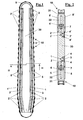
- FIG 1 an overall view is shown of the tool of a chain cutting machine.
- This tool comprises a support body 30 with elongated shape, of minimum thickness with respect to the transversal size, so-called "blade".
- blade 30 On the perimeter of blade 30 a chain loop is dragged comprising a plurality of links 10 on each of which a cutting tip holder is mounted.
- the chain loop slides in a U-shaped guide closed laterally from side plates 5 and 5', connected laterally with respect to the blade by means of screws, for example in number of five for each plate, in a way not shown in the figure, and closed below by a T-shaped guide.
- the tool of the cutting machine needs a lubrication for example with mineral grease, for reducing the friction between the coupled guiding surfaces and the chain.
- Lubrication is obtained with two channels 1 and 1' that extend along a edge of blade 30 for its length within its perimeter, and which are closed to form ducts by respective covers 3 and 3' that follow its form.
- the covers are connected on blade 30, for example, by means of screws in a way not shown.
- the lubricant moreover, starting from said channels 1 and 1', reaches the sliding zone through a plurality of holes 2 and 2' parallel to the mid-plane of the blade and that cross the blade and the T-shaped guide.
- the tool of the chain cutting machine is shown in cross section in figure 2, where blade 30 is shown on whose perimeter the chain is shown with two links 10 thereof, comprising a body 31 and a link element 32.
- the chain slides operatively in the guide obtained with side plates 5 and 5' and with T-shaped guides 6 and 6', connected by screws 7 and 7'.
- the lubrication system provides channels 1 and 1' closed by covers 3 and 3' connected to blade 30 with screws 4 and 4'. Parallel to the mid-plane, moreover, holes 2 and 2' cross both blade 30 and T-shaped guides 6 and 6'.
- Figure 3 shows a complete link 10, which comprises link body 31, the link element 32 and cutting tip holder 11.
- Link body 31 and link element 32 are pivotally connected by pins 34, passing in hole 33.
- the cutting tip holder 11 is coupled to the link body by "dove-tail” engagement and fastened by a screw 13.
- Cutting tips 12 are held by cutting tip holders 11, for friction by the pressure on two opposite sides of a bracket 14, which is connected by tightening a screw 15 in a screw threaded hole present on the cutting tip holders 11.
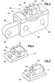
- Figures from 4 to 6 show three further examples of cutting tip holders, in particular, figure 4 shows a cutting tip holder 11 with two aligned cutting tips 12 locked with a bracket 14 and screw 15.
- Figure 5 shows a cutting tip holder 11 with a single cutting tip 12 blocked on the right edge with bracket 14 and screw 15.
- a cutting tip holder 11 is shown with a single cutting tip 12 blocked on the left edge with bracket 14 and screw 15.
- Figure 7 shows a possible succession of cutting tip holders 10, mounted on respective link bodies in a way not shown in the figure.
- the whole succession operatively, forms a whole desired cutting profile, each cutting tip contributing for a portion thereof.
- the overall projection of the profiles of the cutting tips 12 of a whole succession is shown in figure 8.
- FIG. 9 An example of geometry of assembled cutting tips and then of the angles that form the profiles of the cutting tips, so called “cutting edges”, is shown in figures from 9 to 11.
- Figure 9 is an elevational side view and enhances the possible angle for assembling the cutting tip 12, having a lower rake between 5° and 15°.
- Figure 10 is an elevational front view that shows the main cutting angle that has to be less than 12°.
- Figure 11 shows a top plan view of the complete cutting tip holders and in particular, the angle of inclination of the cutting tip 12 with respect to the axis of the chain.
- Another arrangement for correct operation is that of positioning the profile of the cutting edge main at a distance set between 5 and 15mm from the fastening hole of the cutting tip holders to the link body.
Landscapes
- Engineering & Computer Science (AREA)
- Mechanical Engineering (AREA)
- Life Sciences & Earth Sciences (AREA)
- Mining & Mineral Resources (AREA)
- Wood Science & Technology (AREA)
- Forests & Forestry (AREA)
- Cutting Tools, Boring Holders, And Turrets (AREA)
- Lubricants (AREA)
Applications Claiming Priority (2)
| Application Number | Priority Date | Filing Date | Title |
|---|---|---|---|
| ITPI20040038 | 2004-05-26 | ||
| ITPI20040038 ITPI20040038A1 (it) | 2004-05-26 | 2004-05-26 | Macchina tagliatrice a catena per materiali lapidei |
Publications (2)
| Publication Number | Publication Date |
|---|---|
| EP1600235A2 true EP1600235A2 (de) | 2005-11-30 |
| EP1600235A3 EP1600235A3 (de) | 2006-02-08 |
Family
ID=34936973
Family Applications (1)
| Application Number | Title | Priority Date | Filing Date |
|---|---|---|---|
| EP05011420A Withdrawn EP1600235A3 (de) | 2004-05-26 | 2005-05-26 | Kettensäge für Gestein |
Country Status (2)
| Country | Link |
|---|---|
| EP (1) | EP1600235A3 (de) |
| IT (1) | ITPI20040038A1 (de) |
Cited By (5)
| Publication number | Priority date | Publication date | Assignee | Title |
|---|---|---|---|---|
| ITRM20120105A1 (it) * | 2012-03-21 | 2013-09-22 | Fantini Sud S P A | Pezzo di guida modulare, guida modulare, e braccio di una catena di segatrice di pietre ornamentali con tale guida modulare. |
| US20190301282A1 (en) * | 2018-03-29 | 2019-10-03 | Diamond Stone Technologies Inc. | Device and method for cutting quarry stone |
| IT201900016010A1 (it) * | 2019-09-10 | 2021-03-10 | Benetti Macch S P A | Guida modulare per lama segatrice a catena |
| CN113787628A (zh) * | 2021-08-09 | 2021-12-14 | 郑州华菱超硬材料有限公司 | 一种大理石洞采设备专用金刚石链锯刀齿 |
| US12103199B2 (en) | 2019-06-24 | 2024-10-01 | Husqvarna Ab | Rotatable cutting chain work tool, a wall saw arrangement comprising such a work tool, an annular member and a method for producing an annular member |
Family Cites Families (3)
| Publication number | Priority date | Publication date | Assignee | Title |
|---|---|---|---|---|
| DE908296C (de) * | 1950-08-03 | 1954-04-05 | Eugen Moegling | Kettensaegemaschine, deren Kette in Laufrinnen einer Fuehrungsschiene gefuehrt ist |
| US2748810A (en) * | 1955-02-21 | 1956-06-05 | Leonard M Strunk | Chain saw guide bar with lubricating means |
| SE431524C (sv) * | 1980-10-03 | 1989-08-14 | Sandvik Ab | Saagsvaerd |
-
2004
- 2004-05-26 IT ITPI20040038 patent/ITPI20040038A1/it unknown
-
2005
- 2005-05-26 EP EP05011420A patent/EP1600235A3/de not_active Withdrawn
Cited By (7)
| Publication number | Priority date | Publication date | Assignee | Title |
|---|---|---|---|---|
| ITRM20120105A1 (it) * | 2012-03-21 | 2013-09-22 | Fantini Sud S P A | Pezzo di guida modulare, guida modulare, e braccio di una catena di segatrice di pietre ornamentali con tale guida modulare. |
| WO2013139632A1 (en) * | 2012-03-21 | 2013-09-26 | Fantini Sud S.P.A. | Modular guide piece, modular guide, and arm of a sawing machine for sawing ornamental stones with such a modular guide |
| US20190301282A1 (en) * | 2018-03-29 | 2019-10-03 | Diamond Stone Technologies Inc. | Device and method for cutting quarry stone |
| US10526891B2 (en) * | 2018-03-29 | 2020-01-07 | Diamond Stone Technologies Inc. | Device and method for cutting quarry stone |
| US12103199B2 (en) | 2019-06-24 | 2024-10-01 | Husqvarna Ab | Rotatable cutting chain work tool, a wall saw arrangement comprising such a work tool, an annular member and a method for producing an annular member |
| IT201900016010A1 (it) * | 2019-09-10 | 2021-03-10 | Benetti Macch S P A | Guida modulare per lama segatrice a catena |
| CN113787628A (zh) * | 2021-08-09 | 2021-12-14 | 郑州华菱超硬材料有限公司 | 一种大理石洞采设备专用金刚石链锯刀齿 |
Also Published As
| Publication number | Publication date |
|---|---|
| ITPI20040038A1 (it) | 2004-08-26 |
| EP1600235A3 (de) | 2006-02-08 |
Similar Documents
| Publication | Publication Date | Title |
|---|---|---|
| EP1857221B1 (de) | Absaugvorrichtung für ein Abbauwerkzeuggerät | |
| US8869787B2 (en) | Hand-operated implement comprising a cutting chain for cutting mineral and metal materials | |
| US20110225829A1 (en) | Heavy duty configurable shear crusher demolition tool | |
| US7044037B2 (en) | Tip for demolition and construction equipment | |
| WO2014176040A1 (en) | Shear blade having a positive camber and method of adding a positive camber to a shear blade | |
| EP1600235A2 (de) | Kettensäge für Gestein | |
| EP2401106A1 (de) | Scheibenfräserwerkzeug und schneidelement | |
| EP2994260B1 (de) | Werkzeug zum spanenden bearbeiten eines werkstücks | |
| CN105899739A (zh) | 工具保持系统 | |
| DE202005019070U1 (de) | Sägeblatt-Klemmmechanismus für ein Elektro-Werkzeug | |
| SE447665B (sv) | Verktyg for sparjusteringsmaskiner samt sett att tillverka sadana verktyg | |
| JP6173627B1 (ja) | 切断加工用刃物 | |
| US20110146469A1 (en) | Piercing tip for scrap shear | |
| EP2127793A1 (de) | Schneidelement und Fräswerkzeug | |
| DE102009040075B4 (de) | Vorrichtung zur Drehbearbeitung von optischen Werkstücken aus nicht-sprödharten Materialien, insbesondere von Kunststoff-Brillengläsern | |
| DE102011122459A1 (de) | Handfräse | |
| EP3050662A1 (de) | Gewindebohrer mit auswechselbarem schneideinsatz | |
| US4517954A (en) | Removable mount for cutting means | |
| DE19854122A1 (de) | Verfahren und Anordnung zur Befestigung von Schneide-Elementen an einem Stammblatt eines beim Sägen verwendeten Sägeblattes | |
| AU672132B2 (en) | A cutter tool having removable teeth | |
| SE431071B (sv) | Verktyg for spanavskiljande bearbetning av insidan pa ett arbetsstycke | |
| DE102007019357B4 (de) | Schneideinsatz für eine Baumstumpffräse | |
| DE10319957B4 (de) | Werkzeug zur spanabtragenden Bearbeitung | |
| US11052495B2 (en) | Block positioning tool | |
| CN213195895U (zh) | 一种液压联合冲剪机的挡料装置 |
Legal Events
| Date | Code | Title | Description |
|---|---|---|---|
| PUAI | Public reference made under article 153(3) epc to a published international application that has entered the european phase |
Free format text: ORIGINAL CODE: 0009012 |
|
| AK | Designated contracting states |
Kind code of ref document: A2 Designated state(s): AT BE BG CH CY CZ DE DK EE ES FI FR GB GR HU IE IS IT LI LT LU MC NL PL PT RO SE SI SK TR |
|
| AX | Request for extension of the european patent |
Extension state: AL BA HR LV MK YU |
|
| PUAL | Search report despatched |
Free format text: ORIGINAL CODE: 0009013 |
|
| AK | Designated contracting states |
Kind code of ref document: A3 Designated state(s): AT BE BG CH CY CZ DE DK EE ES FI FR GB GR HU IE IS IT LI LT LU MC NL PL PT RO SE SI SK TR |
|
| AX | Request for extension of the european patent |
Extension state: AL BA HR LV MK YU |
|
| AKX | Designation fees paid | ||
| REG | Reference to a national code |
Ref country code: DE Ref legal event code: 8566 |
|
| STAA | Information on the status of an ep patent application or granted ep patent |
Free format text: STATUS: THE APPLICATION IS DEEMED TO BE WITHDRAWN |
|
| 18D | Application deemed to be withdrawn |
Effective date: 20060809 |