EP1600052A2 - Towed rotary swather - Google Patents
Towed rotary swather Download PDFInfo
- Publication number
- EP1600052A2 EP1600052A2 EP05009622A EP05009622A EP1600052A2 EP 1600052 A2 EP1600052 A2 EP 1600052A2 EP 05009622 A EP05009622 A EP 05009622A EP 05009622 A EP05009622 A EP 05009622A EP 1600052 A2 EP1600052 A2 EP 1600052A2
- Authority
- EP
- European Patent Office
- Prior art keywords
- rotary
- rotary rake
- rake
- wheels
- drawbar
- Prior art date
- Legal status (The legal status is an assumption and is not a legal conclusion. Google has not performed a legal analysis and makes no representation as to the accuracy of the status listed.)
- Granted
Links
Images


Classifications
-
- A—HUMAN NECESSITIES
- A01—AGRICULTURE; FORESTRY; ANIMAL HUSBANDRY; HUNTING; TRAPPING; FISHING
- A01D—HARVESTING; MOWING
- A01D78/00—Haymakers with tines moving with respect to the machine
- A01D78/08—Haymakers with tines moving with respect to the machine with tine-carrying rotary heads or wheels
- A01D78/10—Haymakers with tines moving with respect to the machine with tine-carrying rotary heads or wheels the tines rotating about a substantially vertical axis
- A01D78/1085—Having two rows of rotors on two different horizontal lines perpendicular to the advance direction of the machine
Definitions
- the invention relates to a towed rotary windrower according to the preamble of Claim 1.
- towed rotary windrower of this type are the wheels only the second rotary rake with its chassis over the Drawbar of the second rotary rake from the transport position in at least one laterally displaced working position steerable and by means of a drawbar and on Chassis engaging adjusting detectable.
- the first rotary gyro becomes with the main drawbar substantially in the direction of the longitudinal center plane Tractor on its wheels so dragged that its tine orbit on both sides reaches out over the tractor wheel tracks.
- Running in the transport position the second rotary rake the first in the direction of the longitudinal center axis of the tractor to.
- the second rotary rake In a Butlerschwad working position, the second rotary rake is opposite the first rotary rake offset laterally on the side to which the first rotary rake the Promotes crop. In a single swath working position, however, is the second rotary rake offset laterally relative to the first rotary rake to the side of the page turned away, on which the first rotary rake promotes the crop. In this way two single swaths are laid, the z. B. as a night swath or strong Emtegutanfall for a small press forms.
- the respective transfer of the second Rotary gyroscope is by a corresponding rotation of the chassis relative to Drawbar of the second rotary rake set.
- Two individual swaths are less economical for further processing, e.g. through a baler, a shredder or the like, as a double swath or two juxtaposed or superimposed double swath. Because in both working positions the tractor with its wheels in on the Field lying crop moves, the crop can be in the soft soil if necessary which is detrimental to efficient computer work and pollution of the emmental with soil. As the drawbar with regard to a short transport length and good maneuverability only as long as necessary, forms the rear rotary rake in the single swath position a narrower single swath than the first rotary top (limited working width).
- EP 1 145 620 A EP 1 060 651 A, EP 0 845 199 A and EP 0 876 751 A.
- the invention is based on the object, a towed rotary windrower of to create the type mentioned above, with the at least at the edge of the field a more efficient Raking is possible as with the known.
- the tractor drives in sufficient Distance from the edge of the field.
- the first rotary top right to or above the Field edge conveys crop from the field edge inwards to the second rotary rake, the transferred crop with the crop picked up by him in the Vollschwad brings.
- the Vollschwad is well processed, for example by a baler.
- the efficiency of the Rachaille is also high in the field, because by means of the forced adjustment of the first rotary rake so far relative to the longitudinal central axis
- the tractor can be towed laterally offset that the tractor with a Wheel track on an already cleaned ground strip drives.
- a Vollswad formed.
- the risk of not crushing crops pushed into the ground Soiling crops with soil is thus halved. If necessary leaves
- the first rotary gyro even move so far aside that both Traktorradspuren be shaped in the clean field strip.
- other intermediate Vollschwad working positions can be adjusted by means of the forced adjustment device for Adjust the first rotary rake, so that the application width of the towed rotary rake is considerably expanded.
- the forced adjustment device for the first rotary rake is also useful if in addition to the second rotary rake still a third or even another rotary rake should be provided. in principle can, on the one hand to rake efficiently at the edge of the field, or to the pollution of the To minimize harvesting, the forced adjustment even when a towed Rotary windrower be appropriate, equipped only with a large rotary rake is.
- the rotary top prongs are controlled so that in each Working position results in an optimal image.
- the forced adjustment device also leads to the important advantage of a maximum working width in the single swath position according to the sum of the diameter of the tine circumscribing the Rotary gyroscope without the training of the drawbar of the second rotary gyro have to. Because the first rotary top can be moved so far to the side, to no Overlapping is given more.
- the single swath have the same width to each other and substantially equal degrees of filling.
- both rotary gyros are relative to the same side offset to the longitudinal center axis of the tractor so that at least one Traktorradspur in an already cleaned field strip lies.
- the second rotary top can do this expedient to be towed completely outside the two Traktorradspuren.
- the second rotary rake can, as is known, for a higher Rech alloy be designed as the first rotary rake.
- At least one hydraulic cylinder which can be controlled by the tractor as desired or automatically.
- the hydraulic cylinder is supported on an abutment of the main drawbar and steers The wheels of the first rotary rake so that this offset as desired to the side becomes.
- the support frame If the wheels are not steerable a supporting frame of the landing gear are arranged, it is expedient, the support frame to turn by means of the hydraulic cylinder. If the wheels on the support frame are arranged steerable, it may be appropriate to the wheels directly by means of Steer hydraulic cylinder accordingly.
- the wheels are not steerable on the support frame and the support frame itself unrotatable on the drawbar or on the gear housing the rotary rake is arranged, it is expedient, in the main drawbar a To provide articulated joint, in which a main drawbar end part relative to the to the tractor extending main drawbar can bend around the wheels accordingly to steer and steer.
- a shaft axis axis rotatably through the gear housing and with steering devices of the wheels to couple, wherein the hydraulic cylinder engages via a lever on the shaft and adjusts the wheel steering position, and expediently the tine control accordingly adjusted.
- the main drawbar has a main drawbar end piece which can be bent off, the Articulated between the gyro axis and the drawbar for the drawbar second rotary rake, that is, relatively close to the rotor axis.
- the Hydraulic cylinder engages a corresponding abutment of the main drawbar end part to bend this relative to the main drawbar until the desired Side offset of the first rotary rake is set.
- the chassis of the second rotary rake steerable wheels has the chassis of the second rotary rake steerable wheels, and is for Steering the wheels an automatic or optionally activated sequential control intended.
- the wheels of the landing gear of the second rotary rake can be like the Impellers of the chassis of the first rotary rake are steered.
- the sequence control serves to ensure that the second rotary rake the first rotary rake in an exact Predictable and selectable track follows, both in the transport position in straight or cornering, or in a working position with straight or Cornering. This sequential control makes it easier to turn around in sharp turns, for example, when entering the field or on the forecourt, and facilitates it also, to reverse the bends.
- the correct one is Overlap between the first and second rotary rakes finely adjustable and maintainable.
- the steering of the wheels of the second rotary rake takes place, for example. in the opposite direction to the steering direction of the tractor, that is, with the tractor turning to the right the second rotary rake is moved to the left side.
- the rotary gyros are essentially without overlap and therefore with driven maximum working width, forming equal width single swath.
- the sequence control a steering command generator having the relative kink angle of either the main drawbar to the longitudinal central axis of the tractor or in the tow point between the main drawbar and the Removing drawbar and converted into appropriate steering commands.
- the steering commander For example, may have a sensing lever on the main drawbar connected and hinged to a reference point on the tractor. alternative This feeler could also be between the drawbar and the main drawbar be provided in the area of the Werins. The latter solution is the Preference given because the connection conditions on the tractor are simplified. Furthermore, it may be appropriate to provide an actuator at the Switzerlandyak to the Adjust the bending angle between the main drawbar and the drawbar and be able to set.
- a Einzelschwad working position is advantageous in the means of the Forced adjustment of the first rotary rake and by means of its own steering device also the second rotary top with angled main drawbar and in opposite directions angled drawbar are each offset so far to the side that no Overlap more arises, but equal width with maximum possible working width Individual swaths are formed.
- a trailer shown in Fig. 1 consists of a tractor S and a towed Rotary mower K, which is shown in Fig. 1 in the transport position T and the tractor S in a transport direction DT is towed (straight ahead).
- the tractor S drives with its rear wheels 1, 2 (and the front wheels, not shown) in Traktorradspuren 3, 4.
- On a towing device 5 of the tractor S is with a towing connection 6, a main drawbar H of the rotary rake K at least laterally pivotally connected.
- the main drawbar H contains an articulated joint 7 with in approximately ground-parallel bending axis and is connected to a transmission housing 8 of a first Rotary gyro R1 connected, the tines 9 define a tine circulation path 10.
- the tines 9 are controllable with a tine control device, not shown.
- the first rotary rake R1 has its own chassis F1 with an example with the transmission housing 8 connected support frame 12, to the plurality of wheels 11 are arranged. In the embodiment shown, only two wheels 11 shown, but it could also be provided more than two wheels.
- a drawbar Z for a second rotary rake R2 to one approximately to Bottom vertical axis pivoted.
- the drawbar Z contains at least an articulated joint 7 'with approximately ground-parallel bending axis and is connected to the transmission housing 8 'of the second rotary rake R2 connected.
- the tines 9 'of the second Rotary rakes R2 define a tine circulation path 10 'whose diameter is the same or different from the diameter of the tine orbit 10 may be. Also the tines 9 'are controlled.
- the second rotary rake R2 has a support frame 12 'for ground wheels 11', which belong to the chassis F2.
- the drawbars H, Z extend approximately in extension of the longitudinal central axis of the tractor S.
- a forced adjustment device V provided with the first rotary rake R1 relative to Longitudinal axis Y of the tractor S can move to one or the other side.
- Fig. 2 shows the team in a field edge Vollschwad working position.
- the tractor S moves in a direction DR approximately parallel to a field edge FR, between the Traktorradspur 4 and the field edge FR adhered to a "safe" transverse distance X. becomes.
- the first rotary rake R1 is relative to the longitudinal center axis Y of the tractor S to Side of the field edge FR offset, such that the zinc orbit 10 to close to the one to, or over the edge of the field FR.
- the main drawbar is H pivoted counterclockwise. This laterally offset position of the first Rotary gyro R1 is adjusted by means of the forced adjustment device V thereby that the wheels 11 in the direction DR first taken to the right and then run (as shown) parallel to the field edge FR.
- the second rotary rake R2 is relative to the first rotary rake R1 to the other side offset, such that in the direction DR a certain overlap exists and picked up by the first rotary rake R1 crop to the second rotary rake R2 passed and is introduced by this in a Vollschwad VS.
- the second Rotary rake R2 is offset so far that its tine orbit 10 'a Distance of the one Traktorradspur 4 complies, and on the other Traktorradspur third reaches out.
- the drawbar Z is pivoted in the tow point P in the clockwise direction, by, for example, a corresponding steering operation on the wheels 11 ', for example, with its support frame 12' counterclockwise order the gyroscope axis are twisted.
- Fig. 3 illustrates a field Vollschwad working position of the team.
- the tractor S drives on the field in the direction of travel DA (straight ahead), in such a way that the Traktorradspur 3 on the crop E and the other Traktorradspur 4 on a is already running clean field strip, that is, an edge SR of the clean field strip lies between the two Traktorradspuren 3, 4.
- the first rotary rake R1 is seen in the direction of travel DA relative to the longitudinal central axis Y of the tractor S so far to the left that the tine orbit 10 straight the edge SR overlaps, but the Traktorradspur 4 maintains a distance. On the outside, the tine circulation path 10 reaches far beyond the tractor wheel track 3. Of the Main drawbar H is at the Ankupplungsstelle 5 of the tractor S in a clockwise direction pivoted. This laterally offset position is adjusted by the forced adjustment device V of the first rotary rake R1.
- the second rotary rake R2 is offset to the same side as the first rotary rake R1 and moves completely with the required overlap to the first rotary rake R1 outside the Traktorradspuren 3, 4, from the recorded by the first rotary rake R1 and handed over crop and from the second rotary rake R2 additionally picked crop to form a single Vollschwad VS.
- Of the Drawbar Z of the second rotary rake R2 is pivoted in the drawing point P in the clockwise direction.
- the laterally offset positions of both rotary rakes R1, R2 are e.g. adjusted and held by appropriate steering operations of the wheels 11, 11 '.
- FIGS. 4 to 6 illustrate various embodiments of the forced adjustment device V of the first rotary rake R1, wherein the tines and the tine control device have been omitted for the sake of clarity.
- the transmission housing 8 is incorporated in the main drawbar H, in the Distance from the pull point P for the drawbar Z is located.
- a defining the gyro axis Shaft 19 passes through the gear housing and is connected to the support frame 12 of the Chassis F1 rotatably connected.
- the support frame 12 of the chassis F1 holds the Wheels 11.
- With the shaft 19 is also the only schematically indicated tine control device 23 functionally coupled.
- On the shaft 19 is a lever 22nd attached to which a hydraulic cylinder 21 attacks, located on an abutment 20 of the main drawbar H is supported.
- the shaft 19 via the adjusting lever 22nd twisted (double arrow). This twist is transmitted to the support frame 12, to steer the wheels 11, and may also be applied to the tine control device 23 be transmitted.
- the forced-displacement device in FIG. 5 differs from that of FIG. 4 in that that the wheels 11 are mounted steerable on the support frame 12 (with steering joints 24, steering levers 25 and tie rods 26).
- the support frame 12 is either with the Main drawbar H or the transmission housing 8 firmly connected.
- the the gearbox 8 from top to bottom passing through shaft 19 is via an intermediate lever 27 coupled to the tie rods 26.
- the hydraulic cylinder 21, located on the abutment 20 is supported, engages the free end of the control lever 22 to depending on the application To steer the wheels 11 and to keep in the selected steering position. In this case, the tine control 23 can be adjusted accordingly.
- the support frame 12 of the wheels 11 is fixed to the transmission housing. 8 connected to a main drawbar end portion 28.
- the main drawbar end part 28 is bent in an articulated joint 29 with the main drawbar H connected (kink axis approximately perpendicular to the ground).
- the articulation 29 is close to the gyro axis or between the gyro axis and the traction point P for the drawbar Z positioned.
- the main drawbar H is over a hydraulic cylinder, which is supported directly on the tractor S, in the Ankupplungsstelle. 5 pivotable relative to the longitudinal center axis Y of the tractor S to the first rotary rake R1 to move laterally as desired and keep in the deflected position.
- the wheels could optionally be arranged self-steering.
- the second rotary rudder forcibly the tracking or manipulating the first rotary gyro can be followed by a sequencer be provided to direct the second rotary rake R2 as desired. This is explained with reference to FIG. 7.
- the wheels 11 'of the second rotary rake R2 are either directly steerable (analog to Fig. 5) or via the support frame 12 '(analogous to FIG. 4) or by means of a bendable drawbar end portion (analogous to FIG. 6). Another possibility exists therein, in the region of the draw point P between the main drawbar H and the drawbar Z to provide a hydraulic cylinder 16, with a desired bending angle adjustable and durable.
- the sequencer C has a steering command generator 14 on, for example, the bending angle between the main drawbar H and the Tractor S picks up and converts into steering commands.
- This steering command generator 14 may be a sensing lever which pivots in an abutment 15 on Main drawbar H and also pivotable on an abutment 13 of the tractor S is supported, and laterally from the towing connection 6 of the main drawbar H. Das respective steering command is transmitted via a signal transmission 18 to the steering device For example, the wheels 11 'transmitted.
- the steering command generator 14 e.g. a sensing lever, disposed at the position of the hydraulic cylinder 16 at the pull point P, to the bending angle between the main drawbar H and the drawbar Z to tap and convert into appropriate steering commands.
- the operator in the tractor S itself via a corresponding Control valve transmits a steering command to the wheels 11 'to these as desired to steer and to maneuver the second rotary rake R2.
- the hydraulic cylinder 16 could also be omitted, so that the second rotary rake R2 only by steering its wheels 11 'in the respective desired relative position the first rotary rake R1 and / or the tractor S can be set.
- Fig. 8 optical Einzelschwad position
- the drawbars H, Z relative to the direction of travel Angled in opposite directions, so that the rotary rakes R1, R2 equal width single swath ES shape, without that the zinc orbits 10, 10 'transverse to the direction of travel overlap significantly.
- the forced adjustment device V the main drawbar H to one side of the longitudinal center axis Y of the tractor S. inclined (by steering the wheels 11 of the rotary rake R1), while the Steering device L of the rotary rake R2 the drawbar Z to the other side at an angle has made (by steering the wheels 11 ').
Landscapes
- Life Sciences & Earth Sciences (AREA)
- Environmental Sciences (AREA)
- Agricultural Machines (AREA)
- Soil Working Implements (AREA)
- Harvester Elements (AREA)
- Handcart (AREA)
- Harvesting Machines For Specific Crops (AREA)
- Addition Polymer Or Copolymer, Post-Treatments, Or Chemical Modifications (AREA)
Abstract
Description
Die Erfindung betrifft einen geschleppten Kreiselschwader gemäß Oberbegriff des Anspruchs 1.The invention relates to a towed rotary windrower according to the preamble of Claim 1.
Bei einem aus DE 89 08 404 U bekannten, geschleppten Kreiselschwader dieser Art sind die Laufräder nur des zweiten Rechkreisels mit ihrem Fahrgestell gegenüber dem Zugbalken des zweiten Rechkreisels aus der Transportposition in mindestens eine seitlich versetzte Arbeitsposition lenkbar und mittels eines am Zugbalken und am Fahrgestell angreifenden Verstellmittels feststellbar. Hingegen wird der erste Rechkreisel mit dem Hauptzugbalken im Wesentlichen in Richtung der Längsmittelebene des Traktors auf seinen Laufrädern so geschleppt, dass seine Zinkenumlaufbahn beiderseits über die Traktorradspuren nach außen greift. In der Transportposition läuft der zweite Rechkreisel dem ersten in Richtung der Längsmittelachse des Traktors nach. In einer Vollschwad-Arbeitsstellung ist der zweite Rechkreisel gegenüber dem ersten Rechkreisel seitlich auf die Seite versetzt, zu der der erste Rechkreisel das Erntegut fördert. In einer Einzelschwad-Arbeitsposition ist hingegen der zweite Rechkreisel gegenüber dem ersten Rechkreisel seitlich zu der Seite versetzt, die der Seite abgewandt ist, auf die der erste Rechkreisel das Erntegut fördert. Auf diese Weise werden zwei Einzelschwade gelegt, die man z. B. als Nachtschwade oder bei starkem Emtegutanfall für eine kleine Presse bildet. Die jeweilige Versetzung des zweiten Rechkreisels wird durch eine entsprechende Verdrehung des Fahrwerks relativ zum Zugbalken des zweiten Rechkreisels eingestellt. Zwei Einzelschwaden sind weniger ökonomisch für die weitere Verarbeitung, z.B. durch eine Ballenpresse, einen Häcksler oder dgl., als ein Doppelschwad oder zwei neben- oder übereinandergelegte Doppelschwade. Da in beiden Arbeitspositionen der Traktor mit seinen Rädern im auf dem Feld liegenden Erntegut fährt, kann das Erntegut in den gegebenenfalls weichen Boden gedrückt werden, was einer effizienten Recharbeit abträglich ist und zur Verschmutzung des Emteguts mit Erdreich führt. Da der Zugbalken im Hinblick auf eine kurze Transportlänge und gute Manövrierbarkeit nur so lang wie nötig ist, formt der hintere Rechkreisel in der Einzelschwad-Position einen schmäleren Einzelschwad als der erste Rechkreisel (beschränkte Arbeitsbreite). In a known from DE 89 08 404 U, towed rotary windrower of this type are the wheels only the second rotary rake with its chassis over the Drawbar of the second rotary rake from the transport position in at least one laterally displaced working position steerable and by means of a drawbar and on Chassis engaging adjusting detectable. On the other hand, the first rotary gyro becomes with the main drawbar substantially in the direction of the longitudinal center plane Tractor on its wheels so dragged that its tine orbit on both sides reaches out over the tractor wheel tracks. Running in the transport position the second rotary rake the first in the direction of the longitudinal center axis of the tractor to. In a Vollschwad working position, the second rotary rake is opposite the first rotary rake offset laterally on the side to which the first rotary rake the Promotes crop. In a single swath working position, however, is the second rotary rake offset laterally relative to the first rotary rake to the side of the page turned away, on which the first rotary rake promotes the crop. In this way two single swaths are laid, the z. B. as a night swath or strong Emtegutanfall for a small press forms. The respective transfer of the second Rotary gyroscope is by a corresponding rotation of the chassis relative to Drawbar of the second rotary rake set. Two individual swaths are less economical for further processing, e.g. through a baler, a shredder or the like, as a double swath or two juxtaposed or superimposed double swath. Because in both working positions the tractor with its wheels in on the Field lying crop moves, the crop can be in the soft soil if necessary which is detrimental to efficient computer work and pollution of the emmental with soil. As the drawbar with regard to a short transport length and good maneuverability only as long as necessary, forms the rear rotary rake in the single swath position a narrower single swath than the first rotary top (limited working width).
Bei einem anderen geschleppten Kreiselschwader dieser Art (EP 0 950 347 A) ist zwar der Zugpunkt für den Zugbalken des zweiten Rechkreisels optimal weit vorne positioniert, um günstige Abknickwinkel im Gelenkwellenstrang zu erzielen und die Reaktionskräfte zu minimieren, die von den Fahrwerken erzeugt werden. Da jedoch der erste Rechkreisel in jeder Arbeitsposition im Wesentlichen in Verlängerung der Längsmittelachse des Traktors geschleppt wird, fährt der Traktor im Erntegut. Ferner ist es schwierig, am Feldrand sauber zu rechen, falls in diesem Bereich Bodenunregelmäßigkeiten oder Bäume vorhanden sind, weil der Traktor und/oder die Traktorkabine gefährdet ist und gegebenenfalls der Traktor nicht weit genug an den Feldrand heranzufahren vermag. In der Einzelschwad-Position ist der Einzelschwad des zweiten Rechkreisels schmäler als des des ersten Rechkreisels, weil trotz des weit vorne platzierten Zugpunkts eine Überlappung der Rechbahnen verbleibt.In another towed rotary windrower of this type (EP 0 950 347 A) Although the pull point for the drawbar of the second rotary rake optimally far forward positioned to achieve favorable Abknickwinkel in the propeller shaft and the Minimize reaction forces generated by the landing gear. However, since the first rotary top in each working position essentially in extension of the Tractor is traversed in the crop along the longitudinal center axis of the tractor. Further It is difficult to rake clean at the edge of the field, if in this area ground irregularities or trees are present because of the tractor and / or the tractor cab endangered and possibly the tractor is not far enough to the edge of the field can drive up. In the single swath position, the single swath is the second Rotary gyros narrower than that of the first rotary gyros, because despite the far forward Placed Zugpunkt an overlap of the ridges remains.
Weiterer Stand der Technik ist enthalten in EP 1 145 620 A, EP 1 060 651 A, EP 0 845 199 A und EP 0 876 751 A.Further prior art is contained in EP 1 145 620 A, EP 1 060 651 A, EP 0 845 199 A and EP 0 876 751 A.
Der Erfindung liegt die Aufgabe zugrunde, einen geschleppten Kreiselschwader der eingangs genannten Art zu schaffen, mit dem zumindest am Feldrand eine effizientere Recharbeit möglich ist als mit den bekannten.The invention is based on the object, a towed rotary windrower of to create the type mentioned above, with the at least at the edge of the field a more efficient Raking is possible as with the known.
Die gestellte Aufgabe wird mit den Merkmalen des Anspruchs 1 gelöst.The stated object is achieved with the features of claim 1.
Da sich der erste Rechkreisel mittels der Zwangsverstellvorrichtung so weit relativ zur Mittellängsachse des Traktors seitlich versetzen lässt, dass seine Zinkenumlaufbahn über eine Traktorradspur hinausgreift, wird insbesondere am Feldrand auch dann effizient gearbeitet, wenn Hindemisse vorliegen sollten. Der Traktor fährt dann in ausreichendem Abstand vom Feldrand. Der erste Rechkreisel recht bis zum oder über den Feldrand hinaus und fördert Erntegut vom Feldrand einwärts zum zweiten Rechkreisel, der das übergebene Erntegut mit dem von ihm aufgenommenen Erntegut in den Vollschwad bringt. Der Vollschwad ist gut beispielsweise durch eine Ballenpresse weiterverarbeitbar. Die Effizienz der Recharbeit ist auch auf dem Feld hoch, weil sich mittels der Zwangsverstellvorrichtung der erste Rechkreisel so weit relativ zur Längsmittelachse des Traktors seitlich versetzt schleppen lässt, dass der Traktor mit einer Radspur auf einem bereits gesäuberten Bodenstreifen fährt. Auch hierbei wird ein Vollschwad gebildet. Die Gefahr, ins Erdreich gedrücktes Erntegut nicht zu rechen oder Erntegut mit Erdreich zu verschmutzen, ist somit halbiert. Gegebenenfalls lässt sich der erste Rechkreisel sogar so weit zur Seite versetzen, dass beide Traktorradspuren im sauberen Feldstreifen geformt werden. Aber auch andere Zwischen-Vollschwad-Arbeitsstellungen lassen sich mittels der Zwangsverstellvorrichtung für den ersten Rechkreisel einstellen, so dass die Einsatzbreite des geschleppten Kreiselschwaders erheblich erweitert ist. Natürlich können, falls gewünscht, auch zwei Einzelschwade gebildet werden. Die Zwangsverstellvorrichtung für den ersten Rechkreisel ist auch zweckmäßig, wenn zusätzlich zum zweiten Rechkreisel noch ein dritter oder sogar noch ein weiterer Rechkreisel vorgesehen sein sollte. Grundsätzlich kann, einerseits um am Feldrand effizient zu rechen, oder um die Verschmutzung des Ernteguts zu minimieren, die Zwangsverstellvorrichtung sogar bei einem geschleppten Kreiselschwader zweckmäßig sein, der nur mit einem großen Rechkreisel ausgestattet ist. Selbstverständlich sind die Rechkreisel-Zinken so gesteuert, dass sich in jeder Arbeitsposition ein optimales Rechbild ergibt. Die Zwangsverstellvorrichtung führt ferner zu dem wichtigen Vorteil einer maximalen Arbeitsbreite in der Einzelschwad-Position entsprechend der Summe der Durchmesser der Zinkenumlaufbahnen der Rechkreisel, ohne den Zugbalken des zweiten Rechkreisels überlang ausbilden zu müssen. Denn der erste Rechkreisel lässt sich soweit zur Seite verlegen, bis keine Überlappung mehr gegeben ist. Die Einzelschwade haben untereinander gleiche Breite und im Wesentlichen gleiche Füllungsgrade.Since the first rotary rake by means of the forced adjustment so far relative to The longitudinal axis of the tractor can offset laterally that its tine orbit Beyond a Traktorradspur, especially at the field edge is also efficient worked when hindrances should be present. The tractor then drives in sufficient Distance from the edge of the field. The first rotary top right to or above the Field edge and conveys crop from the field edge inwards to the second rotary rake, the transferred crop with the crop picked up by him in the Vollschwad brings. The Vollschwad is well processed, for example by a baler. The efficiency of the Racharbeit is also high in the field, because by means of the forced adjustment of the first rotary rake so far relative to the longitudinal central axis The tractor can be towed laterally offset that the tractor with a Wheel track on an already cleaned ground strip drives. Also here is a Vollswad formed. The risk of not crushing crops pushed into the ground Soiling crops with soil is thus halved. If necessary leaves The first rotary gyro even move so far aside that both Traktorradspuren be shaped in the clean field strip. But also other intermediate Vollschwad working positions can be adjusted by means of the forced adjustment device for Adjust the first rotary rake, so that the application width of the towed rotary rake is considerably expanded. Of course, if you want, you can have two Single swath are formed. The forced adjustment device for the first rotary rake is also useful if in addition to the second rotary rake still a third or even another rotary rake should be provided. in principle can, on the one hand to rake efficiently at the edge of the field, or to the pollution of the To minimize harvesting, the forced adjustment even when a towed Rotary windrower be appropriate, equipped only with a large rotary rake is. Of course, the rotary top prongs are controlled so that in each Working position results in an optimal image. The forced adjustment device also leads to the important advantage of a maximum working width in the single swath position according to the sum of the diameter of the tine circumscribing the Rotary gyroscope without the training of the drawbar of the second rotary gyro have to. Because the first rotary top can be moved so far to the side, to no Overlapping is given more. The single swath have the same width to each other and substantially equal degrees of filling.
In der Feldrand-Vollschwad-Arbeitsposition ist es zweckmäßig, wenn die Zinkenumlaufbahn des ersten Rechkreisels seitlich über die eine Fahrspur des Traktors nach außen bis zum Feldrand greift, während dieselbe Zinkenumlaufbahn innen zwischen den Traktorradspuren einen Abstand zur anderen Traktorradspur einhält. Hingegen ist der zweite Rechkreisel zur anderen Seite so versetzt, dass ein sauberer Vollschwad gebildet wird und seine Zinkenumlaufbahn über die andere Traktorradspur nach außen greift. In the field edge Vollschwad working position, it is useful if the zinc orbit of the first rake laterally over the one lane of the tractor after engages outside to the field edge, while the same tine in orbit intervenes between the Traktorradspuren keeps a distance to the other Traktorradspur. On the other hand is the second rotary rake offset to the other side so that a clean Vollschwad is formed and its zinc orbit over the other Traktorradspur outward attacks.
In der Feld-Vollschwad-Arbeitsposition sind beide Rechkreisel zur selben Seite relativ zur Längsmittelachse des Traktors so versetzt, dass zumindest eine Traktorradspur in einem bereits gesäuberten Feldstreifen liegt. Der zweite Rechkreisel kann dabei zweckmäßig vollständig außerhalb der beiden Traktorradspuren geschleppt werden.In the field full swath working position, both rotary gyros are relative to the same side offset to the longitudinal center axis of the tractor so that at least one Traktorradspur in an already cleaned field strip lies. The second rotary top can do this expedient to be towed completely outside the two Traktorradspuren.
Dieses Prinzip ist besonders zweckmäßig für einen geschleppten Kreiselschwader, dessen Rechkreisel-Zinkenumlaufbahnendurchmesser größer als das Außenmaß der Traktorradspuren ist. Der zweite Rechkreisel kann, wie dies bekannt ist, für eine höhere Rechleistung ausgelegt sein als der erste Rechkreisel.This principle is particularly useful for a towed rotary swather, whose rake-tine orbit diameter is larger than the outer dimension of Tractor wheel tracks is. The second rotary rake can, as is known, for a higher Rechleistung be designed as the first rotary rake.
Um dem Maschinenführer die Recharbeit so komfortabel zu machen wie möglich, ist es zweckmäßig, in der Zwangsverstellvorrichtung wenigstens einen Hydrozylinder vorzusehen, der sich vom Traktor aus nach Wunsch oder automatisch steuern lässt. Der Hydrozylinder stützt sich an einem Widerlager des Hauptzugbalkens ab und lenkt die Laufräder des ersten Rechkreisels so, dass dieser wie gewünscht zur Seite versetzt wird. Hierfür gibt es mehrere Möglichkeiten. Falls die Laufräder nicht lenkbar an einem Stützrahmen des Fahrwerks angeordnet sind, ist es zweckmäßig, den Stützrahmen mittels des Hydrozylinders zu verdrehen. Falls die Laufräder am Stützrahmen lenkbar angeordnet sind, kann es zweckmäßig sein, die Laufräder direkt mittels des Hydrozylinders entsprechend zu lenken. Falls die Laufräder nicht lenkbar am Stützrahmen und der Stützrahmen selbst unverdrehbar am Zugbalken oder am Getriebegehäuse des Rechkreisels angeordnet ist, ist es zweckmäßig, im Hauptzugbalken ein Knickgelenk vorzusehen, in welchem sich ein Hauptzugbalken-Endteil relativ zu dem zum Traktor verlaufenden Hauptzugbalken knicken lässt, um die Laufräder entsprechend zu lenken und gelenkt zu halten.To make the computer work as comfortable as possible for the machine operator is it is expedient, in the forced adjustment at least one hydraulic cylinder which can be controlled by the tractor as desired or automatically. The hydraulic cylinder is supported on an abutment of the main drawbar and steers The wheels of the first rotary rake so that this offset as desired to the side becomes. There are several possibilities for this. If the wheels are not steerable a supporting frame of the landing gear are arranged, it is expedient, the support frame to turn by means of the hydraulic cylinder. If the wheels on the support frame are arranged steerable, it may be appropriate to the wheels directly by means of Steer hydraulic cylinder accordingly. If the wheels are not steerable on the support frame and the support frame itself unrotatable on the drawbar or on the gear housing the rotary rake is arranged, it is expedient, in the main drawbar a To provide articulated joint, in which a main drawbar end part relative to the to the tractor extending main drawbar can bend around the wheels accordingly to steer and steer.
Wird der Stützrahmen des Fahrwerks verdreht, dann ist es zweckmäßig, den Stützrahmen mit einer die Kreiselachse definierenden Welle zu koppeln, an der der Hydrozylinder über einen Stellhebel angreift. Dies bietet den Vorteil, dass auch die Zinkensteuerkurve durch die Welle entsprechend mitverstellt werden kann.If the support frame of the chassis twisted, then it is appropriate to the support frame to couple with a shaft defining the gyro axis, at the hydraulic cylinder attacks via a lever. This offers the advantage that even the tine control curve can be adjusted accordingly by the wave.
Bei lenkbaren Laufrädern ist es zweckmäßig, eine die Kreiselachse definierende Welle drehbar durch das Getriebegehäuse zu führen und mit Lenkeinrichtungen der Laufräder zu koppeln, wobei der Hydrozylinder über einen Stellhebel an der Welle angreift und die Räderlenkstellung einstellt, und zweckmäßig auch die Zinkensteuerung entsprechend verstellt.For steerable wheels, it is expedient to define a shaft axis axis rotatably through the gear housing and with steering devices of the wheels to couple, wherein the hydraulic cylinder engages via a lever on the shaft and adjusts the wheel steering position, and expediently the tine control accordingly adjusted.
Falls der Hauptzugbalken einen abknickbaren Hauptzugbalken-Endteil hat, sollte das Knickgelenk zwischen der Kreiselachse und dem Zugpunkt für den Zugbalken des zweiten Rechkreisels positioniert sein, d.h., relativ nahe bei der Kreiselachse. Der Hydrozylinder greift dann an einem entsprechenden Widerlager des Hauptzugbalken-Endteils an, um dieses relativ zum Hauptzugbalken abzuknicken, bis die gewünschte Seitenversetzung des ersten Rechkreisels eingestellt ist.If the main drawbar has a main drawbar end piece which can be bent off, the Articulated between the gyro axis and the drawbar for the drawbar second rotary rake, that is, relatively close to the rotor axis. Of the Hydraulic cylinder then engages a corresponding abutment of the main drawbar end part to bend this relative to the main drawbar until the desired Side offset of the first rotary rake is set.
Bei einer bevorzugten Ausführungsform mit eigenständiger erfinderischer Bedeutung weist das Fahrwerk des zweiten Rechkreisels lenkbare Laufräder auf, und ist zum Lenken der Laufräder eine automatische oder wahlweise aktivierbare Folgesteuerung vorgesehen. Die Laufräder des Fahrwerks des zweiten Rechkreisels können wie die Laufräder des Fahrwerks des ersten Rechkreisels gelenkt werden. Die Folgesteuerung dient dazu, dass der zweite Rechkreisel dem ersten Rechkreisel in einer exakt vorherbestimmbaren und wählbaren Bahn folgt, und zwar sowohl in der Transportposition bei Gerade- oder Kurvenfahrt, oder in einer Arbeitsposition bei Gerade- oder Kurvenfahrt. Diese Folgesteuerung gestattet es, in scharfen Kurven leichter zu wenden, beispielsweise beim Einfahren in das Feld oder am Vorgelände, und erleichtert es auch, Kurven rückwärts zu fahren. Ferner ist in der Vollschwad-Position die korrekte Überlappung zwischen den ersten und zweiten Rechkreiseln feiner einstellbar und einhaltbar. Dabei erfolgt die Lenkung der Laufräder des zweiten Rechkreisels z.B. gegensinnig zur Lenkrichtung des Traktors, d.h., bei nach rechts abbiegendem Traktor wird der zweite Rechkreisel nach links seitlich verfahren. In der Einzelschwad-Position werden die Rechkreisel im Wesentlichen ohne Überlappung und deshalb mit maximal möglicher Arbeitsbreite gefahren, wobei sie gleichbreite Einzelschwade formen.In a preferred embodiment with independent inventive significance has the chassis of the second rotary rake steerable wheels, and is for Steering the wheels an automatic or optionally activated sequential control intended. The wheels of the landing gear of the second rotary rake can be like the Impellers of the chassis of the first rotary rake are steered. The sequence control serves to ensure that the second rotary rake the first rotary rake in an exact Predictable and selectable track follows, both in the transport position in straight or cornering, or in a working position with straight or Cornering. This sequential control makes it easier to turn around in sharp turns, for example, when entering the field or on the forecourt, and facilitates it also, to reverse the bends. Further, in the full swath position, the correct one is Overlap between the first and second rotary rakes finely adjustable and maintainable. In this case, the steering of the wheels of the second rotary rake takes place, for example. in the opposite direction to the steering direction of the tractor, that is, with the tractor turning to the right the second rotary rake is moved to the left side. In the single swath position The rotary gyros are essentially without overlap and therefore with driven maximum working width, forming equal width single swath.
Hierbei ist es zweckmäßig, wenn die Folgesteuerung einen Lenkkommandogeber aufweist, der den relativen Knickwinkel entweder des Hauptzugbalkens zur Längsmittelachse des Traktors oder im Zugpunkt zwischen dem Hauptzugbalken und dem Zugbalken abgreift und in entsprechende Lenkkommandos umwandelt. Der Lenkkommandogeber kann beispielsweise einen Tasthebel aufweisen, der am Hauptzugbalken angeschlossen und an einer Referenzstelle am Schlepper angelenkt ist. Alternativ könnte dieser Tasthebel auch zwischen dem Zugbalken und dem Hauptzugbalken im Bereich des Zugpunktes vorgesehen sein. Der letztgenannten Lösung wird der Vorzug gegeben, weil die Anschlussverhältnisse am Traktor dadurch vereinfacht sind. Ferner kann es zweckmäßig sein, ein Stellglied beim Zugpunkt vorzusehen, um den Knickwinkel zwischen dem Hauptzugbalken und dem Zugbalken abgreifen, einstellen und festlegen zu können.It is expedient if the sequence control a steering command generator having the relative kink angle of either the main drawbar to the longitudinal central axis of the tractor or in the tow point between the main drawbar and the Removing drawbar and converted into appropriate steering commands. The steering commander For example, may have a sensing lever on the main drawbar connected and hinged to a reference point on the tractor. alternative This feeler could also be between the drawbar and the main drawbar be provided in the area of the Zugpunktes. The latter solution is the Preference given because the connection conditions on the tractor are simplified. Furthermore, it may be appropriate to provide an actuator at the Zugpunkt to the Adjust the bending angle between the main drawbar and the drawbar and be able to set.
Schließlich ist eine Einzelschwad-Arbeitsposition vorteilhaft, in der mittels der Zwangsverstellvorrichtung der erste Rechkreisel und mittels seiner eigenen Lenkvorrichtung auch der zweite Rechkreisel mit abgewinkeltem Hauptzugbalken und gegensinnig abgewinkeltem Zugbalken jeweils soweit zur Seite versetzt sind, dass keine Überlappung mehr entsteht, sondern mit maximal möglicher Arbeitsbreite gleichbreite Einzelschwaden geformt werden. In jedem Einzelfall ist es zweckmäßig, den Zugpunkt relativ weit vor der Kreislachse des ersten Rechkreisels anzuordnen, auch im Hinblick auf dem günstige bzw. moderate Knickwinkel in den Gelenkwellensträngen.Finally, a Einzelschwad working position is advantageous in the means of the Forced adjustment of the first rotary rake and by means of its own steering device also the second rotary top with angled main drawbar and in opposite directions angled drawbar are each offset so far to the side that no Overlap more arises, but equal width with maximum possible working width Individual swaths are formed. In each individual case, it is convenient to the Zugpunkt to be arranged relatively far in front of the salmon of the first rotary rake, also in the Regard to the favorable or moderate bending angle in the propeller shaft strands.
Ausführungsformen des Erfindungsgegenstandes werden anhand der Zeichnungen beschrieben. Es zeigen:
- Fig. 1
- eine Schemadraufsicht auf ein Gespann aus einem Traktor und einem geschleppten Kreiselschwader, in Transportposition,
- Fig. 2
- eine Schemadraufsicht auf das Gespann in einer Feldrand-Doppelschwad-Arbeitsposition,
- Fig. 3
- eine Schemadraufsicht des Gespanns in einer Feld-Doppelschwad-Arbeitsposition,
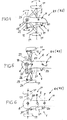
- Fig. 4
- eine Detaildraufsicht zu einem ersten Rechkreisel mit einer Zwangsverstellvorrichtung,
- Fig. 5
- eine Detaildraufsicht auf eine andere Ausführungsform eines ersten Rechkreisels,
- Fig. 6
- eine Detaildraufsicht auf eine weitere Ausführungsform eines ersten Rechkreisels,
- Fig. 7
- eine Schemadraufsicht auf das Gespann bei einer weiteren Ausführungsform mit einer Folgesteuerung zum Lenken des zweiten Rechkreisels, am Beispiel einer vom Traktor gefahrenen Rechtskurve, und
- Fig. 8
- das Gespann in einer optimalen Einzelschwad-Position.
- Fig. 1
- a schematic top view of a team of a tractor and a towed rotary swather, in transport position,
- Fig. 2
- a schematic plan view of the team in a field edge double swath working position,
- Fig. 3
- a schematic top view of the team in a field double swath working position,
- Fig. 4
- a detailed plan view of a first rotary rake with a forced adjustment,
- Fig. 5
- a detailed plan view of another embodiment of a first rotary rake,
- Fig. 6
- a detailed plan view of another embodiment of a first rotary rake,
- Fig. 7
- a schematic plan view of the team in a further embodiment with a sequencer for steering the second rotary rake, using the example of a tractor driven right turn, and
- Fig. 8
- the team in an optimal single swath position.
Ein in Fig. 1 gezeigtes Gespann besteht aus einem Traktor S und einem geschlepptem
Kreiselmäher K, der in Fig. 1 in der Transportstellung T gezeigt ist und vom Traktor
S in einer Transportrichtung DT geschleppt wird (Geradeausfahrt). Der Traktor S
fährt mit seinen Hinterrädern 1, 2 (und den nicht gezeigten Vorderrädern) in Traktorradspuren
3, 4. An einer Schleppvorrichtung 5 des Traktors S ist mit einem Schleppanschluss
6 ein Hauptzugbalken H des Kreiselschwaders K zumindest seitlich
schwenkbar angeschlossen. Der Hauptzugbalken H enthält ein Knickgelenk 7 mit in
etwa bodenparalleler Knickachse und ist an ein Getriebegehäuse 8 eines ersten
Rechkreisels R1 angeschlossen, dessen Zinken 9 eine Zinkenumlaufbahn 10 definieren.
Die Zinken 9 sind mit einer nicht gezeigten Zinkensteuervorrichtung steuerbar.
Der erste Rechkreisel R1 besitzt ein eigenes Fahrwerk F1 mit einem beispielsweise
mit dem Getriebegehäuse 8 verbundenen Stützrahmen 12, an dem mehrere Laufräder
11 angeordnet sind. In der gezeigten Ausführungsform sind nur zwei Laufräder 11
gezeigt, es könnten jedoch auch mehr als zwei Laufräder vorgesehen sein.A trailer shown in Fig. 1 consists of a tractor S and a towed
Rotary mower K, which is shown in Fig. 1 in the transport position T and the tractor
S in a transport direction DT is towed (straight ahead). The tractor S
drives with its rear wheels 1, 2 (and the front wheels, not shown) in
In einem zwischen dem Getriebegehäuse 8 und dem Knickgelenk 7 positionierten
Zugpunkt P ist ein Zugbalken Z für einen zweiten Rechkreisel R2 um eine in etwa zum
Boden vertikale Achse schwenkbar angelenkt. Auch der Zugbalken Z enthält wenigstens
ein Knickgelenk 7' mit in etwa bodenparalleler Knickachse und ist mit dem Getriebegehäuse
8' des zweiten Rechkreisels R2 verbunden. Die Zinken 9' des zweiten
Rechkreisels R2 definieren eine Zinkenumlaufbahn 10', deren Durchmesser gleich
oder verschieden von dem Durchmesser der Zinkenumlaufbahn 10 sein kann. Auch
die Zinken 9' werden gesteuert. Der zweite Rechkreisel R2 weist einen Stützrahmen
12' für Bodenlaufräder 11' auf, die zu dem Fahrwerk F2 gehören.Positioned in between the
Bei dem in Fig. 1 gezeigten Kreiselschwader sind die Durchmesser der Zinkenumlaufbahnen
10, 10' größer als das Außenmaß der Traktorradspuren 3, 4. In der Transportposition
erstrecken sich die Zugbalken H, Z in etwa in Verlängerung der Längsmittelachse
des Traktors S. Zumindest für den ersten Rechkreisel R1 ist eine Zwangsverstellvorrichtung
V vorgesehen, mit der sich der erste Rechkreisel R1 relativ zur
Längsmittelachse Y des Traktors S zur einen oder zur anderen Seite versetzen lässt.In the rotary rake shown in Fig. 1, the diameter of the
Fig. 2 zeigt das Gespann in einer Feldrand-Vollschwad-Arbeitsposition. Der Traktor S
fährt in einer Richtung DR in etwa parallel zu einem Feldrand FR, wobei zwischen der
Traktorradspur 4 und dem Feldrand FR ein "sicherer" Querabstand X eingehalten
wird. Der erste Rechkreisel R1 ist relativ zur Längsmittelachse Y des Traktors S zur
Seite des Feldrandes FR versetzt, derart, dass die Zinkenumlaufbahn 10 bis nahe an
den, an den, oder über den Feldrand FR greift. Innenseitig hält die Zinkenumlaufbahn
10 von der anderen Traktorradspur 3 einen Abstand ein. Der Hauptzugbalken H ist
entgegen dem Uhrzeigersinn verschwenkt. Diese seitwärts versetzte Position des ersten
Rechkreisels R1 ist mittels der Zwangsverstellvorrichtung V dadurch eingestellt,
dass die Laufräder 11 in der Fahrtrichtung DR zunächst nach rechts eingeschlagen
wurden und dann (wie gezeigt) parallel zum Feldrand FR laufen.Fig. 2 shows the team in a field edge Vollschwad working position. The tractor S
moves in a direction DR approximately parallel to a field edge FR, between the
Der zweite Rechkreisel R2 ist relativ zum ersten Rechkreisel R1 zur anderen Seite
versetzt, derart, dass in Fahrtrichtung DR eine bestimmte Überlappung vorliegt und
vom ersten Rechkreisel R1 aufgenommenes Erntegut an den zweiten Rechkreisel R2
übergeben und von diesem in einen Vollschwad VS eingebracht wird. Der zweite
Rechkreisel R2 ist so weit zur Seite versetzt, dass seine Zinkenumlaufbahn 10' einen
Abstand von der einen Traktorradspur 4 einhält, und über die andere Traktorradspur 3
nach außen greift. Der Zugbalken Z ist im Zugpunkt P im Uhrzeigersinn verschwenkt,
und zwar durch beispielsweise einen entsprechenden Lenkvorgang an den Laufrädern
11', die beispielsweise mit ihrem Stützrahmen 12' gegen den Uhrzeigersinn um
die Kreiselachse verdreht sind. The second rotary rake R2 is relative to the first rotary rake R1 to the other side
offset, such that in the direction DR a certain overlap exists and
picked up by the first rotary rake R1 crop to the second rotary rake R2
passed and is introduced by this in a Vollschwad VS. The second
Rotary rake R2 is offset so far that its tine orbit 10 'a
Distance of the one
Fig. 3 verdeutlicht eine Feld-Vollschwad-Arbeitsposition des Gespanns. Der Traktor S
fährt auf dem Feld in der Fahrtrichtung DA (Geradeausfahrt), und zwar derart, dass
die Traktorradspur 3 auf dem Erntegut E und die andere Traktorradspur 4 auf einem
bereits sauberen Feldstreifen läuft, d.h., ein Rand SR des sauberen Feldstreifens liegt
zwischen den beiden Traktorradspuren 3, 4.Fig. 3 illustrates a field Vollschwad working position of the team. The tractor S
drives on the field in the direction of travel DA (straight ahead), in such a way that
the
Der erste Rechkreisel R1 ist in Fahrtrichtung DA gesehen relativ zur Längsmittelachse
Y des Traktors S so weit nach links versetzt, dass die Zinkenumlaufbahn 10 gerade
den Rand SR überlappt, jedoch zur Traktorradspur 4 einen Abstand einhält. Außenseitig
greift die Zinkenumlaufbahn 10 weit über die Traktorradspur 3 hinaus. Der
Hauptzugbalken H ist an der Ankupplungsstelle 5 des Traktors S im Uhrzeigersinn
verschwenkt. Diese seitlich versetzte Position ist eingestellt durch die Zwangsverstellvorrichtung
V des ersten Rechkreisels R1.The first rotary rake R1 is seen in the direction of travel DA relative to the longitudinal central axis
Y of the tractor S so far to the left that the
Der zweite Rechkreisel R2 ist zur selben Seite wie der erste Rechkreisel R1 versetzt
und fährt mit der erforderlichen Überlappung zum ersten Rechkreisel R1 vollständig
außerhalb der Traktorradspuren 3, 4, um aus dem vom ersten Rechkreisel R1 aufgenommenen
und übergebenen Erntegut und aus dem vom zweiten Rechkreisel R2
zusätzlich aufgenommenen Erntegut einen einzigen Vollschwad VS zu formen. Der
Zugbalken Z des zweiten Rechkreisels R2 ist im Zugpunkt P im Uhrzeigersinn verschwenkt.
Die seitlich versetzten Positionen beider Rechkreisel R1, R2 sind z.B.
durch entsprechende Lenkvorgänge der Laufräder 11, 11' eingestellt und gehalten.The second rotary rake R2 is offset to the same side as the first rotary rake R1
and moves completely with the required overlap to the first rotary rake R1
outside the
Die Fig. 4 bis 6 verdeutlichen verschiedene Ausführungsformen der Zwangsverstellvorrichtung V des ersten Rechkreisels R1, wobei die Zinken und die Zinkensteuervorrichtung der Klarheit wegen weggelassen sind.FIGS. 4 to 6 illustrate various embodiments of the forced adjustment device V of the first rotary rake R1, wherein the tines and the tine control device have been omitted for the sake of clarity.
In Fig. 4 ist in den Hauptzugbalken H das Getriebegehäuse 8 eingegliedert, das im
Abstand vom Zugpunkt P für den Zugbalken Z liegt. Eine die Kreiselachse definierende
Welle 19 durchsetzt das Getriebegehäuse und ist mit dem Stützrahmen 12 des
Fahrwerks F1 drehfest verbunden. Der Stützrahmen 12 des Fahrwerks F1 haltert die
Laufräder 11. Mit der Welle 19 ist ferner die nur schematisch angedeutete Zinkensteuervorrichtung
23 funktionell gekoppelt. An der Welle 19 ist ein Stellhebel 22
angebracht, an welchem ein Hydrozylinder 21 angreift, der sich an einem Widerlager
20 des Hauptzugbalkens H abstützt. Durch Beaufschlagen des zweckmäßig doppelseitig
beaufschlagbaren Hydrozylinders 21 wird die Welle 19 über den Stellhebel 22
verdreht (Doppelpfeil). Diese Verdrehung wird auf den Stützrahmen 12 übertragen,
um die Laufräder 11 zu lenken, und kann auch auf die Zinkensteuervorrichtung 23
übertragen werden.In Fig. 4, the
Die Zwangsverstellvorrichtung in Fig. 5 unterscheidet sich von der von Fig. 4 dadurch,
dass die Laufräder 11 am Stützrahmen 12 lenkbar angebracht sind (mit Lenkgelenken
24, Lenkhebeln 25 und Spurstangen 26). Der Stützrahmen 12 ist entweder mit dem
Hauptzugbalken H oder dem Getriebegehäuse 8 fest verbunden. Die das Getriebegehäuse
8 von oben nach unten durchsetzende Welle 19 ist über einen Zwischenhebel
27 mit den Spurstangen 26 gekoppelt. Der Hydrozylinder 21, der sich am Widerlager
20 abstützt, greift am freien Ende des Stellhebels 22 an, um abhängig von der Beaufschlagung
die Laufräder 11 zu lenken und in der gewählten Lenkstellung zu halten.
Dabei kann auch die Zinkensteuerung 23 entsprechend verstellt werden.The forced-displacement device in FIG. 5 differs from that of FIG. 4 in that
that the
In der Ausführungsform der Zwangsverstellvorrichtung V des ersten Rechkreisels R1
in Fig. 6 ist der Stützrahmen 12 der Laufräder 11 fest mit dem Getriebegehäuse 8
verbunden, das in einen Hauptzugbalken-Endteil 28 eingegliedert ist. Der Hauptzugbalken-Endteil
28 ist in einem Knickgelenk 29 mit dem Hauptzugbalken H abknickbar
verbunden (Knickachse in etwa senkrecht zum Boden). Der Hydrozylinder 21, der sich
am Hauptzugbalken H im Widerlager 20 abstützt, greift an einem Widerlager 30 des
Hauptzugbalken-Endteils 28 bzw. des Getriebegehäuses 8 an. Das Knickgelenk 29 ist
nahe bei der Kreiselachse bzw. zwischen der Kreiselachse und dem Zugpunkt P für
den Zugbalken Z positioniert. Durch Abknicken des Hauptzugbalken-Endteils 28 relativ
zum Hauptzugbalken H werden die Laufräder 11 gelenkt.In the embodiment of the forced adjustment device V of the first rotary rake R1
in Fig. 6, the
Bei einer weiteren, nicht gezeigten Ausführungsform ist der Hauptzugbalken H über einen Hydrozylinder, der sich direkt am Traktor S abstützt, in der Ankupplungsstelle 5 relativ zur Längsmittelachse Y des Traktors S verschwenkbar, um den ersten Rechkreisel R1 wie gewünscht seitlich zu verlagern und in ausgelenkter Position zu halten. Hier könnten die Laufräder wahlweise selbstlenkend angeordnet sein.In another embodiment, not shown, the main drawbar H is over a hydraulic cylinder, which is supported directly on the tractor S, in the Ankupplungsstelle. 5 pivotable relative to the longitudinal center axis Y of the tractor S to the first rotary rake R1 to move laterally as desired and keep in the deflected position. Here, the wheels could optionally be arranged self-steering.
Um sowohl in der Transportposition beim Transport als auch in Arbeitspositionen und auch beim Manövrieren des Gespanns den zweiten Rechkreisel zwangsweise dem ersten Rechkreisel nachzuführen oder zu manipulieren, kann eine Folgesteuerung vorgesehen sein, um den zweiten Rechkreisel R2 wie gewünscht zu lenken. Dies sei anhand Fig. 7 erläutert.To transport both in the transport position and in working positions and even when maneuvering the team the second rotary rudder forcibly the tracking or manipulating the first rotary gyro can be followed by a sequencer be provided to direct the second rotary rake R2 as desired. This is explained with reference to FIG. 7.
Die Laufräder 11' des zweiten Rechkreisels R2 sind entweder direkt lenkbar (analog
zu Fig. 5) oder über den Stützrahmen 12' (analog zu Fig. 4) bzw. mittels eines
abknickbaren Zugbalken-Endteils (analog zu Fig. 6). Eine weitere Möglichkeit besteht
darin, im Bereich des Zugpunktes P zwischen dem Hauptzugbalken H und dem Zugbalken
Z einen Hydrozylinder 16 vorzusehen, mit dem ein gewünschter Knickwinkel
einstellbar und haltbar ist. Die Folgesteuerung C weist einen Lenkkommandogeber 14
auf, der beispielsweise den Knickwinkel zwischen dem Hauptzugbalken H und dem
Traktor S abgreift und in Lenkkommandos umwandelt. Dieser Lenkkommandogeber
14 kann ein Tasthebel sein, der sich verschwenkbar in einem Widerlager 15 am
Hauptzugbalken H und ebenfalls verschwenkbar an einem Widerlager 13 des Traktors
S abstützt, und zwar seitlich vom Schleppanschluss 6 des Hauptzugbalkens H. Das
jeweilige Lenkkommando wird über eine Signalübertragung 18 an die Lenkvorrichtung
beispielsweise der Laufräder 11' übertragen.The wheels 11 'of the second rotary rake R2 are either directly steerable (analog
to Fig. 5) or via the support frame 12 '(analogous to FIG. 4) or by means of a
bendable drawbar end portion (analogous to FIG. 6). Another possibility exists
therein, in the region of the draw point P between the main drawbar H and the drawbar
Z to provide a
Fährt, wie in Fig. 7 gezeigt, der Traktor S eine Rechtskurve in der Richtung DK, dann
werden die Laufräder 11' nach links ausgelenkt. Dies kann auch beim Rückwärtsfahren
erfolgen. Alternativ oder additiv kann über eine Signalübertragung 17 das jeweilige
Lenkkommando auch an den Hydrozylinder 16 übertragen werden, der den gewünschten
Knickwinkel zwischen dem Hauptzugbalken H und dem Zugbalken Z einstellt.Travels as shown in Fig. 7, the tractor S a right turn in the direction DK, then
the wheels 11 'are deflected to the left. This can also be reversed
respectively. Alternatively or additionally, via a
Bei einer nicht gezeigten alternativen Ausführungsform ist der Lenkkommandogeber
14, z.B. ein Tasthebel, an der Position des Hydrozylinders 16 beim Zugpunkt P angeordnet,
um den Knickwinkel zwischen dem Hauptzugbalken H und dem Zugbalken Z
abzugreifen und in entsprechende Lenkkommandos umzuwandeln.In an alternative embodiment, not shown, the
Ferner ist es möglich, dass der Maschinenführer im Traktor S selbst über ein entsprechendes
Steuerventil ein Lenkkommando an die Laufräder 11' überträgt, um diese wie
gewünscht zu lenken und den zweiten Rechkreisel R2 zu manövrieren. Der Hydrozylinder
16 könnte auch weggelassen werden, so dass sich der zweite Rechkreisel R2
nur durch Lenken seiner Laufräder 11' in die jeweils gewünschte Relativposition gegenüber
dem ersten Rechkreisel R1 und/oder dem Traktor S einstellen lässt.It is also possible that the operator in the tractor S itself via a corresponding
Control valve transmits a steering command to the wheels 11 'to these as
desired to steer and to maneuver the second rotary rake R2. The
In Fig. 8 (optimale Einzelschwad-Position) sind die Zugbalken H, Z relativ zur Fahrtrichtung
gegensinnig abgewinkelt, so dass die Rechkreisel R1, R2 gleichbreite Einzelschwade
ES formen, ohne dass sich die Zinkenumlaufbahnen 10, 10' quer zur Fahrtrichtung
nennenswert überlappen. Zu diesem Zweck hat die Zwangsverstellvorrichtung
V den Hauptzugbalken H zur einen Seite der Längsmittelachse Y des Traktors S
schräg gestellt (durch Lenken der Laufräder 11 des Rechkreisels R1), während die
Lenkvorrichtung L des Rechkreisels R2 den Zugbalken Z zur anderen Seite schräg
gestellt hat (durch Lenken dessen Laufräder 11'). Hierbei ist es vorteilhaft, wenn der
Zugpunkt P möglichst weit vor der Kreiselachse des Rechkreisels R1 im Hauptzugbalken
H platziert ist. Diese optimale Arbeitsbreite in der Einzelschwad-Position wird
ohne überlangen Zugbalken Z erzielt, was der Transportlänge und der Manövrierbarkeit
zugute kommt.In Fig. 8 (optimal Einzelschwad position) are the drawbars H, Z relative to the direction of travel
Angled in opposite directions, so that the rotary rakes R1, R2 equal width single swath
ES shape, without that the zinc orbits 10, 10 'transverse to the direction of travel
overlap significantly. For this purpose, the forced adjustment device
V the main drawbar H to one side of the longitudinal center axis Y of the tractor S.
inclined (by steering the
Claims (11)
Applications Claiming Priority (2)
| Application Number | Priority Date | Filing Date | Title |
|---|---|---|---|
| DE202004008500U DE202004008500U1 (en) | 2004-05-28 | 2004-05-28 | Trailed rotary rake |
| DE202004008500U | 2004-05-28 |
Publications (3)
| Publication Number | Publication Date |
|---|---|
| EP1600052A2 true EP1600052A2 (en) | 2005-11-30 |
| EP1600052A3 EP1600052A3 (en) | 2006-02-15 |
| EP1600052B1 EP1600052B1 (en) | 2007-10-31 |
Family
ID=34936051
Family Applications (1)
| Application Number | Title | Priority Date | Filing Date |
|---|---|---|---|
| EP05009622A Active EP1600052B1 (en) | 2004-05-28 | 2005-05-02 | Towed rotary swather |
Country Status (3)
| Country | Link |
|---|---|
| EP (1) | EP1600052B1 (en) |
| AT (1) | ATE376766T1 (en) |
| DE (2) | DE202004008500U1 (en) |
Families Citing this family (1)
| Publication number | Priority date | Publication date | Assignee | Title |
|---|---|---|---|---|
| DE102009034422A1 (en) * | 2009-07-23 | 2011-02-03 | Kverneland Asa | swathers |
Citations (6)
| Publication number | Priority date | Publication date | Assignee | Title |
|---|---|---|---|---|
| DE8908404U1 (en) * | 1989-07-10 | 1989-08-31 | Wilhelm Stoll Maschinenfabrik Gmbh, 3325 Lengede, De | |
| EP0845199A1 (en) * | 1996-11-26 | 1998-06-03 | Kuhn S.A. | Haymaking machine |
| EP0876751A1 (en) * | 1997-04-08 | 1998-11-11 | Maasland N.V. | An implement for displacing crop lying on the soil |
| EP0950347A1 (en) * | 1998-04-17 | 1999-10-20 | Kverneland Gottmadingen GmbH & Co. KG | Haymakingmachine |
| EP1060651A1 (en) * | 1999-06-18 | 2000-12-20 | NIEMEYER Landmaschinen GmbH | Haymaking machine especially rotary swather |
| EP1145620A1 (en) * | 2000-04-12 | 2001-10-17 | Claas Saulgau Gmbh | Haymaking machine |
-
2004
- 2004-05-28 DE DE202004008500U patent/DE202004008500U1/en not_active Expired - Lifetime
-
2005
- 2005-05-02 DE DE502005001805T patent/DE502005001805D1/en active Active
- 2005-05-02 EP EP05009622A patent/EP1600052B1/en active Active
- 2005-05-02 AT AT05009622T patent/ATE376766T1/en active
Patent Citations (6)
| Publication number | Priority date | Publication date | Assignee | Title |
|---|---|---|---|---|
| DE8908404U1 (en) * | 1989-07-10 | 1989-08-31 | Wilhelm Stoll Maschinenfabrik Gmbh, 3325 Lengede, De | |
| EP0845199A1 (en) * | 1996-11-26 | 1998-06-03 | Kuhn S.A. | Haymaking machine |
| EP0876751A1 (en) * | 1997-04-08 | 1998-11-11 | Maasland N.V. | An implement for displacing crop lying on the soil |
| EP0950347A1 (en) * | 1998-04-17 | 1999-10-20 | Kverneland Gottmadingen GmbH & Co. KG | Haymakingmachine |
| EP1060651A1 (en) * | 1999-06-18 | 2000-12-20 | NIEMEYER Landmaschinen GmbH | Haymaking machine especially rotary swather |
| EP1145620A1 (en) * | 2000-04-12 | 2001-10-17 | Claas Saulgau Gmbh | Haymaking machine |
Also Published As
| Publication number | Publication date |
|---|---|
| EP1600052A3 (en) | 2006-02-15 |
| EP1600052B1 (en) | 2007-10-31 |
| ATE376766T1 (en) | 2007-11-15 |
| DE202004008500U1 (en) | 2005-10-06 |
| DE502005001805D1 (en) | 2007-12-13 |
Similar Documents
| Publication | Publication Date | Title |
|---|---|---|
| EP0316896B1 (en) | Hay-making machine | |
| DE3137115A1 (en) | MULTI-ROW MAIZE AND / OR CORN CHOPPER | |
| DE2858680C2 (en) | ||
| EP1364573A2 (en) | Haymaker | |
| EP1839480B1 (en) | Rotary windrower | |
| DE4206504C2 (en) | Haymaking machine | |
| EP0455022B1 (en) | Haymaking machine | |
| EP1600052B1 (en) | Towed rotary swather | |
| EP2277370B1 (en) | Rotary rake | |
| EP0950347B1 (en) | Haymakingmachine | |
| DE602005005143T2 (en) | Hay-making machine | |
| DE2844235A1 (en) | HAY ADVERTISING MACHINE | |
| DE2349176B2 (en) | Rake | |
| EP3735818B1 (en) | Agricultural machine | |
| DE102006042552A1 (en) | Rotary tedder has at least six rakes mounted on two arms which are angled forward in working position and can be pivoted back about vertical pivots until they are parallel and can then be raised about horizontal pivots to vertical position | |
| DE10330381B4 (en) | Hay-making machine | |
| DE202006010712U1 (en) | Rotary tedder has at least six rakes mounted on two arms which are angled forward in working position and can be pivoted back about vertical pivots until they are parallel and can then be raised about horizontal pivots to vertical position | |
| DE10110096A1 (en) | Agricultural harvesting machine for hay has beams towed by tractor with tines on extendable rotating beams supported by pairs of wheels | |
| DE102006014652A1 (en) | Rotary tedder has at least six rakes mounted on two arms which are angled forward in working position and can be pivoted back about vertical pivots until they are parallel and can then be raised about horizontal pivots to vertical position | |
| DE10327883B4 (en) | Hay-making machine | |
| DE102014208071B4 (en) | Between an operating and a transport position adjustable agricultural implement | |
| DE1482216C (en) | Slope control device for agricultural machines, in particular hoe harvesting machines | |
| DE10327705B3 (en) | Hay-making machine | |
| DE2642782A1 (en) | Large area soil working system - uses tools driven by two power units with articulated couplings allowing turning and swivelling at ends of rows | |
| DE4331311A1 (en) | Hay tedder with rotor bar on supporting wheels |
Legal Events
| Date | Code | Title | Description |
|---|---|---|---|
| PUAI | Public reference made under article 153(3) epc to a published international application that has entered the european phase |
Free format text: ORIGINAL CODE: 0009012 |
|
| AK | Designated contracting states |
Kind code of ref document: A2 Designated state(s): AT BE BG CH CY CZ DE DK EE ES FI FR GB GR HU IE IS IT LI LT LU MC NL PL PT RO SE SI SK TR |
|
| AX | Request for extension of the european patent |
Extension state: AL BA HR LV MK YU |
|
| PUAL | Search report despatched |
Free format text: ORIGINAL CODE: 0009013 |
|
| AK | Designated contracting states |
Kind code of ref document: A3 Designated state(s): AT BE BG CH CY CZ DE DK EE ES FI FR GB GR HU IE IS IT LI LT LU MC NL PL PT RO SE SI SK TR |
|
| AX | Request for extension of the european patent |
Extension state: AL BA HR LV MK YU |
|
| 17P | Request for examination filed |
Effective date: 20060816 |
|
| AKX | Designation fees paid |
Designated state(s): AT BE BG CH CY CZ DE DK EE ES FI FR GB GR HU IE IS IT LI LT LU MC NL PL PT RO SE SI SK TR |
|
| GRAP | Despatch of communication of intention to grant a patent |
Free format text: ORIGINAL CODE: EPIDOSNIGR1 |
|
| GRAS | Grant fee paid |
Free format text: ORIGINAL CODE: EPIDOSNIGR3 |
|
| GRAA | (expected) grant |
Free format text: ORIGINAL CODE: 0009210 |
|
| AK | Designated contracting states |
Kind code of ref document: B1 Designated state(s): AT BE BG CH CY CZ DE DK EE ES FI FR GB GR HU IE IS IT LI LT LU MC NL PL PT RO SE SI SK TR |
|
| REG | Reference to a national code |
Ref country code: GB Ref legal event code: FG4D Free format text: NOT ENGLISH |
|
| REG | Reference to a national code |
Ref country code: IE Ref legal event code: FG4D Free format text: LANGUAGE OF EP DOCUMENT: GERMAN |
|
| REG | Reference to a national code |
Ref country code: CH Ref legal event code: EP |
|
| REF | Corresponds to: |
Ref document number: 502005001805 Country of ref document: DE Date of ref document: 20071213 Kind code of ref document: P |
|
| NLV1 | Nl: lapsed or annulled due to failure to fulfill the requirements of art. 29p and 29m of the patents act | ||
| PG25 | Lapsed in a contracting state [announced via postgrant information from national office to epo] |
Ref country code: NL Free format text: LAPSE BECAUSE OF FAILURE TO SUBMIT A TRANSLATION OF THE DESCRIPTION OR TO PAY THE FEE WITHIN THE PRESCRIBED TIME-LIMIT Effective date: 20071031 Ref country code: ES Free format text: LAPSE BECAUSE OF FAILURE TO SUBMIT A TRANSLATION OF THE DESCRIPTION OR TO PAY THE FEE WITHIN THE PRESCRIBED TIME-LIMIT Effective date: 20080211 Ref country code: SE Free format text: LAPSE BECAUSE OF FAILURE TO SUBMIT A TRANSLATION OF THE DESCRIPTION OR TO PAY THE FEE WITHIN THE PRESCRIBED TIME-LIMIT Effective date: 20080131 |
|
| GBV | Gb: ep patent (uk) treated as always having been void in accordance with gb section 77(7)/1977 [no translation filed] | ||
| PG25 | Lapsed in a contracting state [announced via postgrant information from national office to epo] |
Ref country code: SI Free format text: LAPSE BECAUSE OF FAILURE TO SUBMIT A TRANSLATION OF THE DESCRIPTION OR TO PAY THE FEE WITHIN THE PRESCRIBED TIME-LIMIT Effective date: 20071031 Ref country code: PT Free format text: LAPSE BECAUSE OF FAILURE TO SUBMIT A TRANSLATION OF THE DESCRIPTION OR TO PAY THE FEE WITHIN THE PRESCRIBED TIME-LIMIT Effective date: 20080331 Ref country code: PL Free format text: LAPSE BECAUSE OF FAILURE TO SUBMIT A TRANSLATION OF THE DESCRIPTION OR TO PAY THE FEE WITHIN THE PRESCRIBED TIME-LIMIT Effective date: 20071031 Ref country code: LT Free format text: LAPSE BECAUSE OF FAILURE TO SUBMIT A TRANSLATION OF THE DESCRIPTION OR TO PAY THE FEE WITHIN THE PRESCRIBED TIME-LIMIT Effective date: 20071031 Ref country code: IS Free format text: LAPSE BECAUSE OF FAILURE TO SUBMIT A TRANSLATION OF THE DESCRIPTION OR TO PAY THE FEE WITHIN THE PRESCRIBED TIME-LIMIT Effective date: 20080229 Ref country code: BG Free format text: LAPSE BECAUSE OF FAILURE TO SUBMIT A TRANSLATION OF THE DESCRIPTION OR TO PAY THE FEE WITHIN THE PRESCRIBED TIME-LIMIT Effective date: 20080131 |
|
| REG | Reference to a national code |
Ref country code: IE Ref legal event code: FD4D |
|
| ET | Fr: translation filed | ||
| PG25 | Lapsed in a contracting state [announced via postgrant information from national office to epo] |
Ref country code: CZ Free format text: LAPSE BECAUSE OF FAILURE TO SUBMIT A TRANSLATION OF THE DESCRIPTION OR TO PAY THE FEE WITHIN THE PRESCRIBED TIME-LIMIT Effective date: 20071031 Ref country code: DK Free format text: LAPSE BECAUSE OF FAILURE TO SUBMIT A TRANSLATION OF THE DESCRIPTION OR TO PAY THE FEE WITHIN THE PRESCRIBED TIME-LIMIT Effective date: 20071031 |
|
| PG25 | Lapsed in a contracting state [announced via postgrant information from national office to epo] |
Ref country code: SK Free format text: LAPSE BECAUSE OF FAILURE TO SUBMIT A TRANSLATION OF THE DESCRIPTION OR TO PAY THE FEE WITHIN THE PRESCRIBED TIME-LIMIT Effective date: 20071031 Ref country code: RO Free format text: LAPSE BECAUSE OF FAILURE TO SUBMIT A TRANSLATION OF THE DESCRIPTION OR TO PAY THE FEE WITHIN THE PRESCRIBED TIME-LIMIT Effective date: 20071031 |
|
| PLBE | No opposition filed within time limit |
Free format text: ORIGINAL CODE: 0009261 |
|
| STAA | Information on the status of an ep patent application or granted ep patent |
Free format text: STATUS: NO OPPOSITION FILED WITHIN TIME LIMIT |
|
| 26N | No opposition filed |
Effective date: 20080801 |
|
| PG25 | Lapsed in a contracting state [announced via postgrant information from national office to epo] |
Ref country code: IE Free format text: LAPSE BECAUSE OF FAILURE TO SUBMIT A TRANSLATION OF THE DESCRIPTION OR TO PAY THE FEE WITHIN THE PRESCRIBED TIME-LIMIT Effective date: 20071031 |
|
| PG25 | Lapsed in a contracting state [announced via postgrant information from national office to epo] |
Ref country code: GB Free format text: LAPSE BECAUSE OF FAILURE TO SUBMIT A TRANSLATION OF THE DESCRIPTION OR TO PAY THE FEE WITHIN THE PRESCRIBED TIME-LIMIT Effective date: 20071031 |
|
| BERE | Be: lapsed |
Owner name: KVERNELAND GROUP GOTTMADINGEN G.M.B.H. & CO. KG Effective date: 20080531 |
|
| PG25 | Lapsed in a contracting state [announced via postgrant information from national office to epo] |
Ref country code: MC Free format text: LAPSE BECAUSE OF NON-PAYMENT OF DUE FEES Effective date: 20080531 |
|
| PG25 | Lapsed in a contracting state [announced via postgrant information from national office to epo] |
Ref country code: GR Free format text: LAPSE BECAUSE OF FAILURE TO SUBMIT A TRANSLATION OF THE DESCRIPTION OR TO PAY THE FEE WITHIN THE PRESCRIBED TIME-LIMIT Effective date: 20080201 Ref country code: EE Free format text: LAPSE BECAUSE OF FAILURE TO SUBMIT A TRANSLATION OF THE DESCRIPTION OR TO PAY THE FEE WITHIN THE PRESCRIBED TIME-LIMIT Effective date: 20071031 |
|
| PG25 | Lapsed in a contracting state [announced via postgrant information from national office to epo] |
Ref country code: FI Free format text: LAPSE BECAUSE OF FAILURE TO SUBMIT A TRANSLATION OF THE DESCRIPTION OR TO PAY THE FEE WITHIN THE PRESCRIBED TIME-LIMIT Effective date: 20071031 |
|
| PG25 | Lapsed in a contracting state [announced via postgrant information from national office to epo] |
Ref country code: BE Free format text: LAPSE BECAUSE OF NON-PAYMENT OF DUE FEES Effective date: 20080531 |
|
| PG25 | Lapsed in a contracting state [announced via postgrant information from national office to epo] |
Ref country code: CY Free format text: LAPSE BECAUSE OF FAILURE TO SUBMIT A TRANSLATION OF THE DESCRIPTION OR TO PAY THE FEE WITHIN THE PRESCRIBED TIME-LIMIT Effective date: 20071031 |
|
| REG | Reference to a national code |
Ref country code: CH Ref legal event code: PL |
|
| PG25 | Lapsed in a contracting state [announced via postgrant information from national office to epo] |
Ref country code: CH Free format text: LAPSE BECAUSE OF NON-PAYMENT OF DUE FEES Effective date: 20090531 Ref country code: LI Free format text: LAPSE BECAUSE OF NON-PAYMENT OF DUE FEES Effective date: 20090531 |
|
| PG25 | Lapsed in a contracting state [announced via postgrant information from national office to epo] |
Ref country code: LU Free format text: LAPSE BECAUSE OF NON-PAYMENT OF DUE FEES Effective date: 20080502 Ref country code: HU Free format text: LAPSE BECAUSE OF FAILURE TO SUBMIT A TRANSLATION OF THE DESCRIPTION OR TO PAY THE FEE WITHIN THE PRESCRIBED TIME-LIMIT Effective date: 20080501 |
|
| PG25 | Lapsed in a contracting state [announced via postgrant information from national office to epo] |
Ref country code: TR Free format text: LAPSE BECAUSE OF FAILURE TO SUBMIT A TRANSLATION OF THE DESCRIPTION OR TO PAY THE FEE WITHIN THE PRESCRIBED TIME-LIMIT Effective date: 20071031 |
|
| PG25 | Lapsed in a contracting state [announced via postgrant information from national office to epo] |
Ref country code: IT Free format text: LAPSE BECAUSE OF NON-PAYMENT OF DUE FEES Effective date: 20080531 |
|
| REG | Reference to a national code |
Ref country code: FR Ref legal event code: PLFP Year of fee payment: 12 |
|
| REG | Reference to a national code |
Ref country code: FR Ref legal event code: PLFP Year of fee payment: 13 |
|
| REG | Reference to a national code |
Ref country code: FR Ref legal event code: PLFP Year of fee payment: 14 |
|
| P01 | Opt-out of the competence of the unified patent court (upc) registered |
Effective date: 20230525 |
|
| PGFP | Annual fee paid to national office [announced via postgrant information from national office to epo] |
Ref country code: FR Payment date: 20230525 Year of fee payment: 19 Ref country code: DE Payment date: 20230519 Year of fee payment: 19 |
|
| PGFP | Annual fee paid to national office [announced via postgrant information from national office to epo] |
Ref country code: AT Payment date: 20230522 Year of fee payment: 19 |