EP1600007B1 - Stereoscopic display arrangement - Google Patents
Stereoscopic display arrangement Download PDFInfo
- Publication number
- EP1600007B1 EP1600007B1 EP04714289A EP04714289A EP1600007B1 EP 1600007 B1 EP1600007 B1 EP 1600007B1 EP 04714289 A EP04714289 A EP 04714289A EP 04714289 A EP04714289 A EP 04714289A EP 1600007 B1 EP1600007 B1 EP 1600007B1
- Authority
- EP
- European Patent Office
- Prior art keywords
- filter
- image
- array
- elements
- arrangement according
- Prior art date
- Legal status (The legal status is an assumption and is not a legal conclusion. Google has not performed a legal analysis and makes no representation as to the accuracy of the status listed.)
- Revoked
Links
Images


Classifications
-
- H—ELECTRICITY
- H04—ELECTRIC COMMUNICATION TECHNIQUE
- H04N—PICTORIAL COMMUNICATION, e.g. TELEVISION
- H04N13/00—Stereoscopic video systems; Multi-view video systems; Details thereof
- H04N13/30—Image reproducers
- H04N13/356—Image reproducers having separate monoscopic and stereoscopic modes
- H04N13/359—Switching between monoscopic and stereoscopic modes
-
- H—ELECTRICITY
- H04—ELECTRIC COMMUNICATION TECHNIQUE
- H04N—PICTORIAL COMMUNICATION, e.g. TELEVISION
- H04N13/00—Stereoscopic video systems; Multi-view video systems; Details thereof
-
- H—ELECTRICITY
- H04—ELECTRIC COMMUNICATION TECHNIQUE
- H04N—PICTORIAL COMMUNICATION, e.g. TELEVISION
- H04N13/00—Stereoscopic video systems; Multi-view video systems; Details thereof
- H04N13/30—Image reproducers
- H04N13/302—Image reproducers for viewing without the aid of special glasses, i.e. using autostereoscopic displays
- H04N13/31—Image reproducers for viewing without the aid of special glasses, i.e. using autostereoscopic displays using parallax barriers
Landscapes
- Engineering & Computer Science (AREA)
- Multimedia (AREA)
- Signal Processing (AREA)
- Testing, Inspecting, Measuring Of Stereoscopic Televisions And Televisions (AREA)
- Image Processing (AREA)
- Control Of Indicators Other Than Cathode Ray Tubes (AREA)
- Eye Examination Apparatus (AREA)
- Electrochromic Elements, Electrophoresis, Or Variable Reflection Or Absorption Elements (AREA)
- Ultra Sonic Daignosis Equipment (AREA)
Abstract
Description
Die Erfindung bezieht sich auf Anordnungen zur räumlichen Darstellung, insbesondere auf derartige, die einem oder mehreren Betrachtern ohne zusätzliche Hilfsmittel wie Brillen ein dreidimensional wahrnehmbares Bild darbieten.The invention relates to arrangements for spatial representation, in particular to those that offer one or more viewers without additional aids such as glasses a three-dimensionally perceptible image.
Im Stand der Technik sind verschiedene derartige Verfahren und Anordnungen bekannt.Various such methods and arrangements are known in the art.
Eine Vielzahl bekannter Verfahren und Anordnungen zur räumlichen Darstellung basiert auf der räumlichen oder der räumlich-zeitlichen Aufteilung verschiedener Ansichten einer Szene auf einem Gerät zur Bildwiedergabe. Bei den Ansichten handelt es sich dabei in der Regel entweder um räumlich in der Tiefe gestaffelte Schichtbilder oder um aus verschiedenen Perspektiven aufgenommene Bilder. Als Geräte zur Bildwiedergabe finden z. B. LC-Displays eine immer weiter verbreitete Anwendung. So werden beispielsweise in
Während diese Verfahren und Anordnungen etliche Vorteile, so etwa die potentielle Verminderung von Moiré-Effekten, die Tauglichkeit für mehrere Betrachter sowie die Vermeidbarkeit von Hilfsmitteln zur räumlichen Wahrnehmbarkeit bietet, sind sie nachteilig von einer verminderten Helligkeit gekennzeichnet.While these methods and arrangements offer several advantages, such as the potential reduction in moiré effects, multi-viewer capability, and the avoidability of spatial perception aids, they are disadvantageously characterized by decreased brightness.
Es ist Aufgabe der vorliegenden Erfindung, Anordnungen der vorgenannten Art derart weiterzubilden, daß eine erhöhte Helligkeit bei der 3D-Darstellung erzielt wird. Weiterhin soll in speziellen Ausgestaltungen der erfindungsgemäßen Anordnungen eine verbesserte Lesbarkeit von gewöhnlichem Text erzielt werden.It is an object of the present invention to develop arrangements of the aforementioned type such that an increased brightness in the 3D display is achieved. Furthermore, in specific embodiments of the arrangements according to the invention an improved readability of ordinary text should be achieved.
Diese Aufgabe wird bei einer Anordnung der vorgenannten Art zur räumlichen Darstellung einer Szene/eines Gegenstandes, umfassend einen Bildgeber mit einer Vielzahl einzelner Bildelemente αij in einem Raster aus Zeilen j und Spalten i, wobei auf den Bildelementen αij Teilinformationen aus mindestens drei Ansichten Ak (k=1...n, n≥3) der Szene/des Gegenstandes wiedergegeben werden, ein oder mehrere Arrays aus einer Vielzahl einzelner, in Zeilen q und Spalten p angeordneter, als Filterelemente βpq ausgeführte Wellenlängen- und/oder Graustufenfilter von denen ein Teil in vorgegebenen Wellenlängenbereichen lichtdurchlässig ist, und der übrige Teil lichtundurchlässig ist und die dem Bildgeber mit den Bildelementen αij in Blickrichtung vor- und/oder nachgeordnet sind, so daß für das von den Bildelementen αij abgestrahlte Licht Ausbreitungsrichtungen vorgegeben werden, wobei jeweils ein Bildelement αij mit mehreren zugeordneten Filterelementen oder ein Filterelement mit mehreren zugeordneten Bildelementen αij derart korrespondiert, daß jeweils die Verbindungsgerade zwischen der Flächenmitte eines sichtbaren Abschnittes des Bildelementes αij und der Flächenmitte eines sichtbaren Abschnittes des Filterelements einer Ausbreitungsrichtung entspricht, wobei sich die Ausbreitungsrichtungen innerhalb eines Betrachtungsraumes, in dem sich der/die Betrachter aufhalten, in einer Vielzahl von Schnittpunkten, die jeweils einer Betrachtungsposition entsprechen, kreuzen, wodurch von jeder Betrachtungsposition aus ein Betrachter mit ei-nem Auge überwiegend Teilinformationen einer ersten Auswahl und mit dem anderen Auge überwiegend Teilinformationen einer zweiten Auswahl aus den Ansichten Ak (k=1...n) optisch wahrnimmt, dadurch gelöst, daß auf mindestens einem der Arrays das Verhältnis der Flächenanteile der für das gesamte sichtbare Spektrum lichtdurchlässigen Filterelemente βpq zur Gesamtfläche aller Filterelemente βpq, multipliziert mit der durchschnittlichen Anzahl n' von den verschiedenen, pro Zeile j des Rasters aus Bildelementen αij dargestellten Ansichten, größer als 1 und höchstens 2 ist.This object is achieved in an arrangement of the aforementioned type for the spatial representation of a scene / an object, comprising an imager with a plurality of individual pixels α ij in a grid of rows j and columns i, wherein on the pixels α ij partial information from at least three views A k (k = 1 ... n, n≥3) of the scene / object, one or more arrays of a plurality of individual arranged in rows q and columns p, as filter elements β pq executed wavelength and / or grayscale filter of which a part is translucent in predetermined wavelength ranges, and the remaining part is opaque and which are forward and / or downstream of the imager with the picture elements α ij in the viewing direction, so that propagation directions are predetermined for the light emitted by the picture elements α ij wherein in each case a picture element α ij with a plurality of associated filter elements or a filter element with corresponds to a plurality of associated pixels α ij such that in each case the connecting line between the center of a visible portion of the pixel α ij and the center of area of a visible portion of the filter element corresponds to a propagation direction, wherein the propagation directions within a viewing space in which the / stay the viewer , in a plurality of points of intersection, each corresponding to a viewing position, crossing, whereby from each viewing position of a viewer with egg nem Eye predominantly partial information of a first selection and with the other eye predominantly partial information of a second selection from the views A k (k = 1 ... n) optically perceives, solved in that on at least one of the arrays, the ratio of the surface areas of the for the entire visible spectrum translucent filter elements β pq to the total area of all filter elements β pq multiplied by the average number n 'of the various views represented per row j of the raster of pixels α ij is greater than 1 and at most 2.
Indem mehr Licht durch die Filterelemente zum Betrachter gelangt, kann die Helligkeit erhöht werden.As more light passes through the filter elements to the viewer, the brightness can be increased.
Der 3D-Eindruck bleibt bei solchen Anordnungen - gegenüber herkömmlichen Anordnungen - ohne spürbare Beeinträchtigungen, bei denen die Transparentfilter so dimensioniert sind, daß pro sichtbarem Rasterabschnitt in bezug auf die Bildelementfläche stets mehr als ein Bildelement αij sichtbar ist. Dies ist insbesondere bei solchen, bevorzugten Ausgestaltungen der Erfindung der Fall, wo der Quotient aus der Summe der Flächenanteile von Filterelementen βpq, die für Licht des im wesentlichen gesamten sichtbaren Spektrums weitestgehend durchlässig sind, und der Summe der Flächenanteile aller Filterelemente βpq des jeweiligen Arrays einen Wert annimmt, der zwischen dem Quotienten Q1=1,1/n' und dem Quotienten Q2=1,8/n' liegt, so daß auf Grund der für das komplette sichtbare Spektrum lichttransmittierenden Filterelemente (βpq) im Mittel pro sichtbarem Rasterabschnitt im Bezug auf die Bildelementfläche stets etwa 1,1 bis 1,8 Bildelemente (αij) sichtbar sind. Versuche haben jedoch gezeigt, daß dies auch bei Quotienten, die größer als 1,8 sind, der Fall ist, beispielsweise bei 2.0.The 3D impression remains in such arrangements - compared to conventional arrangements - without noticeable drawbacks, in which the transparent filters are dimensioned so that per visible raster portion with respect to the pixel surface is always more than one pixel α ij visible. This is particularly the case in such preferred embodiments of the invention, where the quotient of the sum of the surface portions of filter elements β pq , which are largely permeable to light of the substantially entire visible spectrum, and the sum of the surface portions of all filter elements β pq of the respective Arrays assumes a value which lies between the quotient Q1 = 1,1 / n 'and the quotient Q2 = 1,8 / n', so that on the basis of the for the complete visible spectrum light-transmitting filter elements (β pq ) on average per visible Grid section with respect to the pixel surface are always visible about 1.1 to 1.8 pixels (α ij ). However, tests have shown that this is the case even for quotients greater than 1.8, for example at 2.0.
In einer anderen Ausgestaltung der Erfindung entspricht der Ausschnitt bei Parallelprojektion auf das Raster aus Bildelementen αij mindestens einer Zeile j oder mindestens einer Spalte i. In einer bevorzugten Ausgestaltung, bei der ebenfalls der 3D-Eindruck nicht spürbar beeinträchtigt wird, ist bei Parallelprojektion eines genügend großen Filterabschnittes mindestens eines vorgesehenen Arrays aus Filterelementen βpq auf mindestens eine Zeile j oder auf mindestens eine Spalte i des Rasters mindestens die 1,1/n'-fache und höchstens jedoch die 1,8/n'-fache Fläche der entsprechenden Zeile j bzw. Spalte i von für das komplette sichtbare Spektrum im wesentlichen lichtdurchlässigen Filterelementen βpq bedeckt, so daß auf Grund der für das komplette sichtbare Spektrum lichttransmittierenden Filterelemente βpq im Mittel pro sichtbarem Rasterabschnitt im Bezug auf die Bildelementfläche stets etwa 1,1 bis 1,8 Bildelemente αij sichtbar sind.In another embodiment of the invention, the detail corresponds to at least one row j or at least one column i in parallel projection onto the grid of pixels α ij . In a preferred embodiment, in which likewise the 3D impression is not noticeably impaired, with parallel projection of a sufficiently large filter section at least one provided array of filter elements β pq on at least one row j or at least one column i of the grid at least 1.1 / n'-times and at most, however, the 1.8 / n'-times the area of the corresponding line j or column i covered by the entire visible spectrum substantially translucent filter elements β pq , so that due to the entire visible spectrum light transmissive filter elements β pq on average per visible grid section with respect to the pixel surface is always about 1.1 to 1.8 pixels α ij visible.
In einer weiteren bevorzugten Ausgestaltung der Erfindung ist mindestens ein erster von einem Rand des Arrays zu einem gegenüberliegenden Rand reichender und ununterbrochen durchgängiger Gürtel von Transparentfiltern und mindestens ein zweiter von einem Rand des Arrays zu einem gegenüberliegenden Rand reichender und ununterbrochen durchgängiger Gürtel von Transparentfiltern vorgesehen, wobei die Hauptausbreitungsrichtungen dieser beiden Gürtel auf dem Array nicht-parallel zueinander ausgerichtet sind.In a further preferred embodiment of the invention, at least one first belt of transparent filters extending from one edge of the array to an opposite edge and continuously passing through is provided, and at least one second belt of transparent filters extending from one edge of the array to an opposite edge and continuously passing through the main propagation directions of these two belts on the array are non-parallel to each other.
Unter Hauptausbreitungsrichtung wird in diesem Zusammenhang die Verbindungslinie zwischen zwei Transparentfiltern ein- und desselben Gürtels verstanden, die jeweils an entgegengesetzten Enden der Gürtel positioniert sind. Für den Fall, daß gleichzeitig mehrere Transparentfilter an einem Ende des Gürtels positioniert sind, ist der Flächenschwerpunkt der Gesamtfläche der entsprechenden Transparentfilter gemeint.By main propagation direction in this context is meant the connecting line between two transparent filters of one and the same belt, which are respectively positioned at opposite ends of the belts. In the event that several transparent filters are simultaneously positioned at one end of the belt, the centroid of the total area of the corresponding transparent filters is meant.
Hierbei verläuft vorzugsweise mindestens einer der vorgesehenen durchgängigen Gürtel von Transparentfiltern parallel zum oberen, unteren, linken oder rechten Rand des jeweiligen Arrays aus Filterelementen βpq und/oder parallel zum oberen, unteren, linken oder rechten Rand des Rasters aus Bildelementen αij.In this case, preferably at least one of the provided continuous belts of transparent filters runs parallel to the upper, lower, left or right edge of the respective array of filter elements β pq and / or parallel to the upper, lower, left or right edge of the raster of picture elements α ij .
Vorteilhaft ist eine Vielzahl solcher durchgängiger Gürtel von Transparentfiltern vorgesehen.Advantageously, a plurality of such continuous belt is provided by transparent filters.
Es sei an dieser Stelle angemerkt, daß die erfindungsgemäßen Anordnungen unter Umständen, wenn nämlich der oben genannte Quotient im Bereich der unteren Grenze bei etwa 1,1 /n' liegt, auch mit nur zwei dargestellten Ansichten Ak funktionieren.It should be noted at this point that the arrangements according to the invention under certain circumstances, when the abovementioned quotient in the range of the lower limit is about 1.1 / n ', also function with only two views A k shown .
In einer weiteren Ausgestaltung ist mindestens ein Teil der durchgängigen Gürtel von Transparentfiltern zufällig über das Array verteilt angeordnet, insofern besagte Gürtel parallel zueinander liegen. Demgegenüber ist es jedoch auch möglich, daß mindestens ein Teil der durchgängigen Gürtel von Transparentfiltern in periodischen Abständen zueinander auf dem Array angeordnet ist, insofern besagte Gürtel parallel zueinander liegen, wobei bevorzugt jede m. Zeile q (mit m>1) oder aber jede m. Spalte p (mit m>1) des entsprechenden Arrays einen derartigen durchgängigen Gürtel von Transparentfiltern bildet.In a further embodiment, at least a portion of the continuous belts of transparent filters are randomly distributed over the array insofar as said belts are parallel to each other. In contrast, however, it is also possible that at least a portion of the continuous belt of transparent filters at periodic intervals to each other on the array is arranged, as far as said belt are parallel to each other, wherein preferably each m. Line q (with m> 1) or every m. Column p (with m> 1) of the corresponding array forms such a continuous belt of transparent filters.
In einer speziellen Ausgestaltung sind bei Parallelprojektion eines -aber nicht zwingend jedes- solchen durchgängigen Gürtels von Transparentfiltern in Betrachtungsrichtung auf das Raster aus Bildelementen αij vorwiegend solche Bildelemente αij von Transparentfiltern mindestens teilweise überdeckt, die zu einem überwiegenden Anteil oder ausschließlich Teilinformationen ein- und derselben Ansicht Ak wiedergeben. Es ist aber auch möglich, daß mehrere solche Bildelemente αij von Transparentfiltern mindestens teilweise überdeckt sind, die Teilinformationen mindestens zweier verschiedener Ansichten Ak wiedergeben.In a special embodiment, parallel projection of-but not necessarily each such continuous belt of transparent filters in viewing direction on the grid of pixels α ij predominantly such pixels α ij of transparent filters at least partially covered, which to a predominant share or only partial information on and the same view A k play . However, it is also possible for a plurality of such picture elements α ij to be at least partially covered by transparent filters, which reproduce the partial information of at least two different views A k .
Für alle erfindungsgemäßen Anordnungen wird die Zuordnung von Teilinformationen aus den Ansichten Ak (k=l...n) zu Bildelementen αij der Position i,j bevorzugt nach der Funktion 
Ferner werden für vorgesehene Filterarrays die Filterelemente βpq in Abhängigkeit von ihrer Transparenzwellenlänge / ihrem Transparenzwellenlängenbereich / ihrem Transmissionsgrad λb nach der Funktion 
Für die weiter unten beschriebenen Ausführungsbeispiele lassen sich entsprechende Maskenkoeffizientenmatrizen dpq bzw. Koeffizientenmatrizen cij angeben. Dem knapperen Umfang geschuldet wird hier jedoch darauf verzichtet.For the exemplary embodiments described below, corresponding mask coefficient matrices d pq or coefficient matrices c ij can be specified. However, the narrower scope owed here is waived.
Bevorzugt ist genau ein Array aus Filterelementen βpq vorgesehen und der Abstand z zwischen dem besagtem Array und dem Raster aus Bildelementen αij, in Normalenrichtung gemessen, wird nach folgender Gleichung festgelegt: 
Darin bezeichnet sp den mittleren horizontalen Abstand zwischen zwei benachbarten Bildelementen αij. Liegt das Filterarray in Blick- oder Normalenrichtung vor dem Raster aus Bildelementen αij, so wird z von da subtrahiert; liegt das Filterarray dahinter, so wird z zu da addiert. pd ist die mittlere Pupillendistanz bei einem Betrachter und da ein wählbarer Betrachtungsabstand.In this, s p denotes the average horizontal distance between two adjacent picture elements α ij . If the filter array lies in the viewing or normal direction in front of the grid of pixels α ij , then z is subtracted from d a ; if the filter array is behind, then z is added to d a . p d is the mean pupil distance in a viewer and d a is a selectable viewing distance.
Typische Abstände z liegen etwa im Bereich von 1 mm bis zu 25 mm; andere, insbesondere größere Abstände sind jedoch ebenso denkbar.Typical distances z are approximately in the range of 1 mm to 25 mm; however, other, in particular larger distances are also conceivable.
In einer vorteilhaften Ausgestaltung sind alle auf dem bzw. den Filterarrays vorgesehenen Filterelemente gleich groß. Der Flächeninhalt eines Filters bzw. eines Filterelementes kann in diesem Zusammenhang in der Regel eine Fläche von einigen tausend Quadratmikrometern bis hin zu einigen Quadratmillimetern aufweisen. Die Filterelemente bzw. Filter βpq weisen vieleckige, bevorzugt rechteckige Umrisse auf. Ferner können die Umrisse gleichfalls geschwungene Linien beinhalten.In an advantageous embodiment, all filter elements provided on the filter array (s) are the same size. The surface area of a filter or a filter element can in this context generally have an area of a few thousand square microns to a few square millimeters. The filter elements or filters β pq have polygonal, preferably rectangular outlines. Further, the outlines may also include curved lines.
Auch für die Bildelemente αij sind andere Formen, beispielsweise vieleckige Formen oder Streifen nach Art eines Fischgrätenmusters wie bei einem sogenannten Dual-Domain-Display, denkbar. Dies impliziert, daß die Anzahl der vorgesehenen Filterelemente βpq auf einem Filterarray stark von der Anzahl der Bildelementen αij abweichen kann.Also for the picture elements α ij other shapes, such as polygonal shapes or stripes in the manner of a herringbone pattern as in a so-called dual-domain display, conceivable. This implies that the number of filter elements β pq provided on a filter array may differ greatly from the number of pixels α ij .
Für den Fall, daß keine zufällige Anordnung von Transparentfiltergürteln vorgesehen ist, weisen die auf dem bzw. den Filterarrays vorgesehenen Filterelemente βpq bevorzugt jeweils eine im wesentlichen periodische Anordnung auf.In the event that no random arrangement of transparent filter belts is provided, the filter elements β pq provided on the filter array (s) preferably each have an essentially periodic arrangement.
In einer weiteren vorteilhaften Ausgestaltung sind die Lichtausbreitungsrichtungen für die jeweils auf den Bildelementen αij wiedergegebene Teilinformation in Abhängigkeit ihrer Wellenlänge / ihres Wellenlängenbereichs vorgegeben.In a further advantageous refinement, the light propagation directions for the partial information reproduced on the picture elements α ij are predetermined as a function of their wavelength / their wavelength range.
Eine weitere Ausgestaltung sieht vor, daß auf mindestens einem der vorgesehenen Arrays aus Filterelementen in mindestens einer Zeile q des Arrays unmittelbar benachbarte Transparentfilter an eine andere Anzahl unmittelbar benachbart positionierter Transparentfilter auf der Zeile q-1 angrenzen, als auf der Zeile q+1. Auf diese Weise werden die Ansichtenübergänge bei einer Betrachterbewegung beeinflußt.A further embodiment provides that adjacent to at least one of the provided arrays of filter elements in at least one line q of the array immediately adjacent transparent filter to another number immediately adjacent positioned transparent filter on the line q-1, as on the line q + 1. In this way, the views transitions are influenced by a viewer movement.
Bevorzugt ist jedes der vorgesehenen Filterarrays als statisches, zeitlich unveränderliches Filterarray ausgebildet und im wesentlichen in einer fixen Relativposition zum Raster aus Bildelementen αij, d.h. dem Bildgeber, angeordnet.Preferably, each of the provided filter arrays is designed as a static, temporally invariable filter array and arranged substantially in a fixed relative position to the grid of picture elements α ij , ie the imager.
Bei einer weiteren, spezielleren Ausgestaltung der vorgenannten erfindungsgemäßen Anordnungen gibt mindestens ein Bildelement αij eine aus Teilinformationen mindestens zweier verschiedener Ansichten Ak gemischte Bildinformation wieder, beispielsweise mittels eines der in der
Bei den bislang beschriebenen erfindungsgemäßen Anordnungen kann der Bildgeber beispielsweise ein LC-Display, ein Plasmadisplay oder ein OLED-Bildschirm sein. Dies schließt jedoch nicht aus, daß es sich bei dem Bildgeber auch um andersartige Geräte handeln kann.In the arrangements according to the invention described so far, the imager can be, for example, an LC display, a plasma display or an OLED screen. However, this does not exclude that the imager can also be different types of devices.
Bei besonderen Anwendungen kann es überdies gewünscht sein, ganz oder teilweise zwischen einem 2D- und 3D-Modus umzuschalten. Hierzu kommt jede der bislang beschriebenen Anordnungen in Frage, wobei eine transluzente Bildwiedergabeeinrichtung, beispielsweise ein LC-Display, sowie genau ein Array aus Filterelementen vorgesehen ist, welches sich in Betrachtungsrichtung zwischen der Bildwiedergabeeinrichtung und einer Planbeleuchtungseinrichtung befindet. Fernerhin ist eine schaltbare Streuscheibe zwischen der Bildwiedergabeeinrichtung und dem Filterarray vorgesehen, so daß in einer ersten Betriebsart, in welcher die schaltbare Streuscheibe transparent geschaltet ist, für den/die Betrachter ein räumlicher Eindruck erzeugt wird, während in einer zweiten Betriebsart, in welcher die schaltbare Streuscheibe mindestens teilweise streuend geschaltet ist, die Wirkung des Arrays aus Filterelementen weitestgehend aufgehoben ist, so daß das gestreute Licht eine weitestgehend homogene Beleuchtung der Bildwiedergabeeinrichtung ermöglicht und auf dieser zweidimensionale Bildinhalte in voller Auflösung wahrnehmbar dargestellt werden können. In besagtem zweiten Modus werden demnach an den entsprechenden Teilflächen, auf denen die Streuscheibe streuend geschaltet ist, keine Lichtausbreitungsrichtungen mehr vorgegebenen, so daß beide Augen des jeweiligen Betrachters im wesentlichen die gleichen Bildteilinformationen sehen. Vorteilhaft wird an den entsprechenden 2D-Stellen auf dem Bildgeber auch nur zweidimensionale Bildinformation, d.h. kein aus mehreren Ansichten zusammengesetztes Bild dargeboten.For special applications, it may also be desirable to switch completely or partially between a 2D and a 3D mode. For this purpose, each of the arrangements described so far in question, wherein a translucent image display device, such as an LC display, and exactly one array of filter elements is provided, which is located in the viewing direction between the image display device and a plan lighting device. Furthermore, a switchable diffuser between the image display device and the filter array is provided so that in a first mode in which the switchable diffuser is switched transparent, for the / the viewer a spatial impression is generated, while in a second mode in which the switchable Lens is switched at least partially scattering, the effect of the array of filter elements is largely eliminated, so that the scattered light allows a largely homogeneous illumination of the image display device and can be displayed perceptible on this two-dimensional image content in full resolution. In said second mode, accordingly, no light propagation directions are predetermined at the corresponding subareas on which the diffuser is switched, so that both eyes of the respective observer see substantially the same image part information. Advantageously, at the corresponding 2D locations on the imager, only two-dimensional image information, i. no image composed of multiple views.
Ferner kann zur 2D-3D-Umschaltung mindestens ein Array aus Filterelementen vorgesehen sein, welches mindestens teilweise als Wellenlängen- bzw. Graustufenfilter wirkende Pixel mit einem elektrochromen oder photochromen Aufbau beinhaltet, wobei das Array in einer ersten Betriebsart für die 3D-Darstellung insbesondere auch unter Verwendung der elektrochrom bzw. photochrom aufgebauten Pixel eine zur räumlichen Darstellung geeignete Filterarraystruktur exhibiert, während in einer zweiten Betriebsart die elektrochrom bzw. photochrom aufgebauten Pixel so transparent wie möglich, bevorzugt für das komplette sichtbar Spektrum im wesentlichen vollständig transparent, geschaltet werden.
Dabei können sowohl elektrochrom bzw. photochrom aufgebaute als auch in ihren Transmissionseigenschaften unveränderliche Wellenlängen- bzw. Graustufenfilter vorgesehen sein, wobei die unveränderlichen Filter bevorzugt für das komplette sichtbare Spektrum im wesentlichen vollständig transparent ausgebildet sind.Furthermore, at least one array of filter elements can be provided for 2D-3D switching, which at least partially as a wavelength or grayscale filter pixels having an electrochromic or photochromic structure includes, the array in a first mode for the 3D representation in particular under Using the electrochromic or photochromic constructed pixels exhibited suitable for spatial representation Filterarraystruktur while in a second mode, the electrochromic or photochromic pixels as transparent as possible, preferably for the complete visible spectrum substantially completely transparent, are switched.
In this case, both electrochromic or photochromic constructed as well as immutable in their transmission characteristics wavelength or gray level filter can be provided, the invariable filter are preferably formed for the complete visible spectrum substantially completely transparent.
Die Erfindung wird im folgenden an Hand von Zeichnungen näher erläutert.
Es zeigt:
- Fig.1a
- ein Filterarray in einer ersten Ausgestaltung der Erfindung,
- Fig.1b
- die schematische Zusammensetzung von transparenten Filterabschnitten aus mehreren transparenten Filterelementen,
- Fig.1c
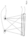
- eine schematische Darstellung der Ausgestaltung erfindungsgemäßer Anordnungen,
- Fig.2
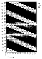
- eine mögliche Bildkombination zur Erzielung eines räumlichen Eindrucks in Verbindung mit einem Filterarray der ersten Ausgestaltung,
- Fig.3 und Fig.4
- Beispiele für mögliche für die beiden Betrachteraugen sichtbaren Bildelemente bzw. Bildelementteilflächen bei Zugrundelegung der Verhältnisse nach Fig.1a und Fig.2,
- Fig.5
- ein weiteres Beispiel der Bildkombination,
- Fig.6
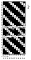
- ein in Verbindung mit der Bildkombinationsvorschrift nach Fig.5 für die räumliche Darstellung sehr gut geeignetes Filterarray,
- Fig.7 und Fig.8
- Beispiele für mögliche für die beiden Betrachteraugen sichtbaren Bildelemente bzw. Bidelementteilflächen bei Zugrundelegung der Verhältnisse nach Fig.5 und Fig.6,
- Fig.9
- ein weiteres Beispiel der Bildkombination,
- Fig.10
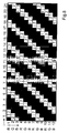
- ein in Verbindung mit der Bildkombinationsvorschrift nach Fig.9 für die räumliche Darstellung sehr gut geeignetes Filterarray,
- Fig.11 und Fig.12
- Beispiele für mögliche für die beiden Betrachteraugen sichtbaren Bildelemente bzw. Bildelementteilflächen bei Zugrundelegung der Verhältnisse nach Fig.9 und Fig.10,
- Fig.13a
- ein Filterarray in einer weiteren Ausgestaltung der Erfindung, vorzugsweise anzuwenden mit einer Bildkombinationsvorschrift nach Fig.9,
- Fig.13b
- die schematische Zusammensetzung von transparenten Filterabschnitten aus mehreren transparenten Filterelementen, äquivalent zu dem Filterarray gezeigt in Fig.13a,
- Fig.14
- ein Beispiel für mögliche für ein Betrachterauge sichtbaren Bildelemente bzw. Bildelementteilflächen bei Zugrundelegung der Verhältnisse nach Fig.9 und Fig.13a,
- Fig.15
- ein Filterarray in einer weiteren Ausgestaltung der Erfindung, vorzugsweise anzuwenden mit einer Bildkombinationsvorschrift nach Fig.9,
- Fig.16
- ein Beispiel für mögliche für ein Betrachterauge sichtbaren Bildelemente bzw. Bildelementteilflächen bei Zugrundelegung der Verhältnisse nach Fig.9 und Fig.15,
- Fig.17
- ein Filterarray in einer weiteren Ausgestaltung der Erfindung, vorzugsweise anzuwenden mit einer Bildkombinationsvorschrift nach Fig.9,
- Fig.18
- ein Beispiel für mögliche für ein Betrachterauge sichtbare Bildelemente bzw, Bildelementteilflächen bei Zugrundelegung der Verhältnisse nach Fig.9 und Fig.17,
- Fig.19
- ein weiteres Beispiel der Bildkombination,
- Fig.20
- ein in Verbindung mit der Bildkombinationsvorschrift nach Fig.19 für die räumliche Darstellung sehr gut geeignetes Filterarray,
- Fig.21 und Fig.22
- Beispiele für mögliche für die beiden Betrachteraugen sichtbaren Bildelemente bzw. Bildelementteilflächen bei Zugrundelegung der Verhältnisse nach Fig.19 und Fig.20,
- Fig.23
- ein weiteres Beispiel der Bildkombination,
- Fig.24
- ein in Verbindung mit der Bildkombinationsvorschrift nach Fig.23 für die räumliche Darstellung sehr gut geeignetes Filterarray,
- Fig.25 und Fig.26
- Beispiele für mögliche für die beiden Betrachteraugen sichtbaren Bildelemente bzw. Bildelementteilflächen bei Zugrundelegung der Verhältnisse nach Fig.23 und Fig.24,
- Fig.27
- ein weiteres Beispiel der Bildkombination,
- Fig.28
- ein in Verbindung mit der Bildkombinationsvorschrift nach Fig.27 für die räumliche Darstellung sehr gut geeignetes Filterarray mit horizontalen Transparentfiltergürteln gemäß der dritten Ausgestaltung der erfindungsgemäßen Anordnungen,
- Fig.29 und Fig.30
- Beispiele für mögliche für die beiden Betrachteraugen sichtbaren Bildelemente bzw. Bildelementteilflächen bei Zugrundelegung der Verhältnisse nach Fig.27 und Fig.28,
- Fig.31
- ein weiteres Beispiel der Bildkombination,
- Fig.32
- ein in Verbindung mit der Bildkombinationsvorschrift nach Fig.31 für die räumliche Darstellung sehr gut geeignetes Filterarray mit vertikalen Transparentfiltergürteln gemäß der dritten Ausgestaltung der erfindungsgemäßen Anordnungen,
- Fig.33 und Fig.34
- Beispiele für mögliche für die beiden Betrachteraugen sichtbaren Bildelemente bzw. Bildelementteilflächen bei Zugrundelegung der Verhältnisse nach Fig.31 und Fig.32,
- Fig.35
- ein weiteres Filterarray, welches den Anforderungen der ersten und zweiten Ausgestaltungen der Erfindung gerecht werden kann, beinhaltend R', G', B'-Filter und Graustufenfilter,
- Fig. 36
- eine weitere mögliche Ausgestaltung für ein Filterarray,
- Fig. 37
- die schematische Zusammensetzung von transparenten Filterabschnitten aus transparenten Filterelementen, wie sie in Fig. 36 verwendet werden,
- Fig. 38
- die in Fig. 37 verwendeten Filterelemente im einzelnen,
- Fig. 39 und Fig. 40
- Beispiele für mögliche, für jeweils eines der beiden Betrachteraugen sichtbaren Bildelemente bzw. Bildelementteilflächen bei Zugrundelegung der Verhältnisse nach Fig.36,
- Fig. 41
- ein weiteres Beispiel mit einer Bildkombination aus sechs Ansichten,
- Fig. 42
- ein Filterarray zur Verwendung mit der in Fig. 41 gezeigten Bildkombination, sowie
- Fig. 43 und Fig. 44
- Beispiele für mögliche, für jeweils eines der beiden Betrachteraugen sichtbaren Bildelemente bzw. Bildelementteilflächen bei Zugrundelegung der Verhältnisse nach Fig.41.
It shows:
- 1a
- a filter array in a first embodiment of the invention,
- 1b shows
- the schematic composition of transparent filter sections made of several transparent filter elements,
- Figure 1C
- a schematic representation of the embodiment of inventive arrangements,
- Fig.2
- a possible image combination for obtaining a spatial impression in connection with a filter array of the first embodiment,
- Fig.3 and Fig.4
- Examples of possible picture elements or picture element sub-areas visible for the two observers on the basis of the conditions according to FIG. 1a and FIG.
- Figure 5
- another example of the image combination,
- Figure 6
- a filter array very well suited for the spatial representation in connection with the image combination rule according to FIG.
- Fig.7 and Fig.8
- Examples of possible picture elements or bid element partial areas visible for the two observers on the basis of the relationships according to FIGS. 5 and 6,
- Figure 9
- another example of the image combination,
- Figure 10
- a filter array which is very well suited for the spatial representation in conjunction with the image combination rule according to FIG.
- Fig.11 and Fig.12
- Examples of possible picture elements or picture element sub-areas visible for the two observers on the basis of the relationships according to FIGS. 9 and 10,
- 13a
- a filter array in a further embodiment of the invention, preferably to be used with an image combination rule according to FIG.
- Figure 13b
- the schematic composition of transparent filter sections of a plurality of transparent filter elements, equivalent to the filter array shown in Fig. 13a,
- Figure 14
- an example of possible picture elements or picture element sub-areas visible to a viewer eye on the basis of the relationships according to FIG. 9 and FIG.
- Figure 15
- a filter array in a further embodiment of the invention, preferably to be used with an image combination rule according to FIG.
- Figure 16
- an example of possible picture elements or picture element sub-areas visible to a viewer eye on the basis of the relationships according to FIGS. 9 and 15,
- Figure 17
- a filter array in a further embodiment of the invention, preferably to be used with an image combination rule according to FIG.
- Figure 18
- an example of possible picture elements or picture element sub-areas visible for a viewer eye on the basis of the relationships according to FIG. 9 and FIG.
- Figure 19
- another example of the image combination,
- fig.20
- a filter array very well suited for the spatial representation in connection with the image combination rule according to FIG.
- Fig.21 and Fig.22
- Examples of possible picture elements or picture element sub-areas which are visible for the two observers' eyes on the basis of the conditions according to FIG. 19 and FIG.
- Figure 23
- another example of the image combination,
- Figure 24
- a filter array very well suited for the spatial representation in conjunction with the image combination rule according to FIG.
- Fig.25 and Fig.26
- Examples of possible image elements or image element subareas visible for the two observers on the basis of the relationships according to FIG. 23 and FIG.
- Fig.27
- another example of the image combination,
- Figure 28
- a filter array with horizontal transparent filter belts, which is very well suited for the spatial representation in conjunction with the image combination rule according to FIG. 27, according to the third embodiment of the arrangements according to the invention,
- Fig.29 and Fig.30
- Examples of possible picture elements or picture element sub-areas visible for the two observers on the basis of the relationships according to FIGS. 27 and 28,
- Fig.31
- another example of the image combination,
- fig.32
- a filter array with vertical transparent filter belts which is very well suited for spatial representation in conjunction with the image combination rule according to FIG. 31, according to the third embodiment of the arrangements according to the invention,
- Fig.33 and Fig.34
- Examples of possible picture elements or picture element subareas visible for the two observers on the basis of the relationships according to FIGS. 31 and 32
- Fig.35
- another filter array that can meet the requirements of the first and second embodiments of the invention, including R ', G', B 'filters and grayscale filters,
- Fig. 36
- another possible embodiment for a filter array,
- Fig. 37
- the schematic composition of transparent filter sections made of transparent filter elements, as used in FIG. 36,
- Fig. 38
- the filter elements used in FIG. 37 in detail,
- FIGS. 39 and 40
- Examples of possible picture elements or picture element sub-areas which are visible for each of the two observer's eyes on the basis of the relationships according to FIG. 36,
- Fig. 41
- another example with a picture combination of six views,
- Fig. 42
- a filter array for use with the image combination shown in Fig. 41, as well as
- FIGS. 43 and 44
- Examples of possible picture elements or picture element sub-areas visible for each of the two observer's eyes, based on the relationships according to FIG.
Alle Zeichnungen sind nicht maßstäblich und -je nach Sachlage- vergrößert oder verkleinert dargestellt. Bei einigen Zeichnungen handelt es sich um schemenhafte Prinzipskizzen bzw. um Ausschnittdarstellungen.All drawings are not to scale and - depending on the circumstances - enlarged or reduced. Some of the drawings are sketchy schematic sketches or snippets.
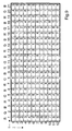
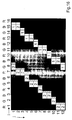
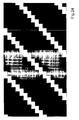
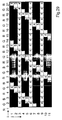
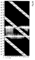
Die Fig.1a stellt - als Ausschnitt - ein Filterarray in einer ersten Ausgestaltung der erfindungsgemäßen Anordnung dar. Das Filterarray ist aus einer Vielzahl von Wellenlängenfiltern aufgebaut. Hierbei sind nur für das sichtbare Spektrum im wesentlichen transparente und opake Filter bzw. Filterelemente vorgesehen. Wie in Fig.1b ersichtlich wird, sind die transparenten Filterabschnitte des aus Fig.1a bekannten Filterarrays aus mehreren transparenten Filterelementen zusammengesetzt. Die Abmessungen der (kleinsten) Transparentfilterelemente sind hier bei Fig.1b ungefähr 0,0997151 mm Breite und 0,2991453 mm Höhe, insofern als Raster aus Bildelementen ein 15.1"LC-Display vom Typ LG mit einer Auflösung von 1024x768 Bildpunkten bei 0,3 mm x 0,3 mm Vollfarbpixelgröße verwendet wird. Die Maße für die zusammengesetzten Transparentfilterabschnitte, die in Fig.1a ersichtlich sind, sind somit inhärent gegeben. Das Filterarray hat in etwa die gleiche flächenmäßige Ausdehnung, wie die aktive Bildfläche eines LC-Displays oder allgemein des Bildgebers.FIG. 1a represents-as a section-a filter array in a first embodiment of the arrangement according to the invention. The filter array is constructed from a multiplicity of wavelength filters. In this case, substantially transparent and opaque filters or filter elements are provided only for the visible spectrum. As can be seen in FIG. 1 b, the transparent filter sections of the filter array known from FIG. 1 a are composed of a plurality of transparent filter elements. The dimensions of the (smallest) transparent filter elements here are approximately 0.0997151 mm wide and 0.2991453 mm high in Fig.1b, in that the pixel grid is a 15.1 "LG type LC display with a resolution of 1024x768 pixels at 0.3 The dimensions of the composite transparent filter sections shown in Figure 1a are thus inherently given The filter array has approximately the same areal extent as the active image area of an LC display or in general of the imager.
Im folgenden wird auf Fig.1c Bezug genommen, in der schematisch angedeutete Betrachteraugen 3 auf ein Filterarray 2 blicken. Wird nun das gezeigte Filterarray 2 wie in Fig.1c gezeigt vor einem Raster 1 aus Zeilen j und Spalten i von Bildelementen αij angeordnet, so ist die erfindungsgemäße Anordnung in einer Ausgestaltung implementiert, bei der der Quotient aus der Summe der Flächenanteile von Filterelementen βpq, die für Licht des im wesentlichen gesamten sichtbaren Spektrums weitestgehend durchlässig sind, und der Summe der Flächenanteile aller Filterelemente βpq des jeweiligen Arrays einen Wert annimmt, der zwischen dem Quotienten Q1=1,1/n' und dem Quotienten Q2=1,8/n' liegt, so daß auf Grund der für das komplette sichtbare Spektrum lichttransmittierenden Filterelemente βpq im Mittel pro sichtbarem Rasterabschnitt im Bezug auf die Bildelementfläche stets etwa 1,1 bis 1,8 Bildelemente αij sichtbar sind. Die in vorgegebenen Wellenlängenbereichen lichtdurchlässigen Filterelemente sind als Transparentfilter ausgestaltet.In the following, reference is made to FIG. 1 c, in which schematically indicated
Hierzu wird auf dem Raster aus Bildelementen ein aus vier Ansichten nach der in Fig.2 gezeigten Bildkombinationsvorschrift zusammengesetztes Bild verwendet. Die Spalten R, G, B bedeuten hier und in weiteren Zeichnungen rote, grüne und blaue Subpixelspalten (bzw. ggf. auch -zeilen). Die durchschnittliche Anzahl von verschiedenen pro Zeile i des Rasters auf den Bildelementen αij zur Darstellung kommenden Ansichten n' ist demnach in diesem Falle n' =4.For this purpose, an image composed of four views according to the image combination rule shown in FIG. 2 is used on the grid of image elements. The columns R, G, B here and in other drawings mean red, green and blue subpixel columns (or possibly also lines). The average number of different views n 'per row i of the grid on the picture elements α ij for display is accordingly n' = 4 in this case.
Wird nun beispielsweise nach Fig.1b ein 12x12-Feld der kleinsten Filterelemente, deren Raster hier erkennbar ist, ausgewählt, so beträgt auf (dem einen vorgesehenen) Array der Quotient aus der Summe der Flächenanteile von Filterelementen βpq, die für Licht des im wesentlichen gesamten sichtbaren Spektrums weitestgehend durchlässig sind, und der Summe der Flächenanteile aller Filterelemente βpq den Wert 48/144=1/3. Unter Zugrundelegung von n'=4 liegt besagter Quotient 1/3 wie gefordert zwischen dem Quotienten Q1=1,1/n'=0,275 und dem Quotienten Q2=1,8/n'=0,45.If, for example, according to FIG. 1b, a 12 × 12 field of the smallest filter elements whose grid is recognizable here is selected, then the quotient of the sum of the surface portions of filter elements β pq , which is essentially the same for light, is on (the one provided) array the entire visible spectrum are largely permeable, and the sum of the area proportions of all filter elements β pq the value 48/144 = 1/3 . Assuming n '= 4, said
Die Fig.3 und Fig.4 zeigen Beispiele für mögliche, für die beiden Betrachteraugen sichtbaren Bildelemente bzw. Bildelementteilflächen bei Zugrundelegung der Verhältnisse nach Fig.1a und Fig.2. Aus diesen wird ersichtlich, daß auf Grund der für das komplette sichtbare Spektrum transmittierenden Filterelemente βpq, d.h. der Transparentfilter, im Mittel pro sichtbarem Rasterabschnitt im Bezug auf die Bildelementfläche stets etwa 1,1 bis 1,8 Bildelemente αij sichtbar sind, hier genauer gesagt etwa 1,33 Bildelemente αij. Beispielsweise grenzen an das linke obere sichtbare Bildelement an der Stelle (1,1) in Fig.3 noch ca. 0,33 sichtbare Bildelemente (bezogen auf die Bildelementfläche) des rechts benachbarten Bildelementes.FIGS. 3 and 4 show examples of possible picture elements or picture element sub-areas which are visible for the two observer's eyes, on the basis of the conditions according to FIGS. 1 a and 2. From these it can be seen that, due to the filter elements β pq transmitting the complete visible spectrum, ie the transparent filter, on average about 1.1 to 1.8 picture elements α ij are always visible per visible screen segment with respect to the picture element area say about 1.33 pixels α ij . For example, at the point (1,1) in FIG. 3, about 0,33 visible picture elements (with respect to the picture element area) of the picture element on the right adjoin the left upper visible picture element.
Auf Grund der hier vorliegenden Sichtverhältnisse (siehe Fig.3) sieht ein Betrachter z.B. eine Auswahl bestehend aus den Ansichten Ak mit k=1, 2, 3 im Verhältnis der sichtbaren Flächenanteile von 3:8:1 zueinander. Das andere Auge des Betrachters, dessen Sichtverhältnisse beispielhaft in Fig.4 illustriert sind, würde beispielsweise eine Auswahl bestehend aus den Ansichten Ak mit k=3, 4, 1 im Verhältnis der sichtbaren Flächenanteile von 3:8:1 zueinander sehen.On the basis of the visual conditions present here (see FIG. 3), a viewer sees, for example, a selection consisting of the views A k with k = 1, 2, 3 in relation to the visible area proportions of 3: 8: 1 to one another. The other eye of the observer whose visibility conditions are illustrated by way of example in FIG. 4 would, for example, see a selection consisting of the views A k with k = 3, 4, 1 in relation to the visible area proportions of 3: 8: 1.
An dieser Stelle sei angemerkt, daß auf Grund der Sichtverhältnisse bei den erfindungsgemäßen Anordnungen die 2D-Textlesbarkeit gegenüber 3D-Anordnungen und -verfahren im Stand der Technik weiter verbessert ist.At this point, it should be noted that due to the visibility in the inventive arrangements, the 2D text readability over 3D arrangements and methods in the prior art is further improved.
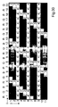
Die Fig.5 zeigt ein weiteres Beispiel der Bildkombination, besonders geeignet für ein mobil einsetzbares Display, wie das eines PDA (Personal Digital Assistent) oder eines Mobiltelefons. Aus der Fig.6 ist ein in Verbindung mit der Bildkombinationsvorschrift nach Fig.5 für die räumliche Darstellung sehr gut geeignetes Filterarray ersichtlich, mit dem sich eine Ausgestaltung realisieren läßt, bei der bei Parallelprojektion eines genügend großen Filterabschnittes mindestens eines vorgesehenen Arrays aus Filterelementen βpq auf mindestens eine Zeile j oder auf mindestens eine Spalte i des Rasters mindestens die 1,1/n'-fache und höchstens jedoch die 1,8/n'-fache Fläche der entsprechenden Zeile j bzw. Spalte i von für das komplette sichtbare Spektrum im wesentlichen lichtdurchlässigen Filterelementen βpq bedeckt ist, so daß auf Grund der für das komplette sichtbare Spektrum lichttransmittierenden Filterelemente βpq im Mittel pro sichtbarem Rasterabschnitt im Bezug auf die Bildelementfläche stets etwa 1,1 bis 1,8 Bildelemente αij sichtbar sind. Die in vorgegebenen Bereichen lichtdurchlässigen Filterelemente sind ebenfalls als Transparentfilter ausgestaltet.5 shows another example of the image combination, particularly suitable for a mobile display, such as a PDA (Personal Digital Assistant) or a mobile phone. FIG. 6 shows a filter array which is very well suited for the spatial representation in conjunction with the image combination specification according to FIG. 5, with which a configuration can be realized in which at parallel projection of a sufficiently large filter section at least one provided array of filter elements .beta. Pq on at least one row j or on at least one column i of the grid at least 1.1 / n 'times and at most the 1.8 / n' times the area of the corresponding row j or column i of the complete visible spectrum substantially translucent filter elements β pq is covered, so that due to the for the complete visible spectrum light-transmitting filter elements β pq on average per visible grid section with respect to the pixel surface always about 1.1 to 1.8 pixels α ij are visible. The translucent in predetermined areas filter elements are also designed as a transparent filter.
Bezugnehmend auf Fig.5 ist die durchschnittliche Anzahl von verschiedenen pro Zeile i des Rasters auf den Bildelementen αij zur Darstellung kommenden Ansichten hier ebenfalls wieder n'=4.Referring to Figure 5, the average number of different on each line i of the grid to the image elements α ij for displaying views coming here also n '=. 4
Während die Fig.7 und Fig.8 Beispiele für mögliche für die beiden Betrachteraugen sichtbaren Bildelemente bzw. Bildelementteilflächen bei Zugrundelegung der Verhältnisse nach Fig.5 und Fig.6 bzw. bezüglich einer Relativanordnung nach Fig.1c zeigen, lassen sich erstgenannte Zeichnungen auch zur Illustration der geforderten Eigenschaften heranziehen:
- Insofern der Abstand z zwischen dem Filterarray und dem Raster aus Bildelementen nicht allzu groß, d.h. in bezug auf den gewählten Betrachtungsabstand da für die
Betrachteraugen 3 etwa kleiner einem Prozent, ist, geben die Zeichnungen Fig.7 und Fig.8 gleichsam in etwa Parallelprojektionen des Filterarrays auf das Raster aus Bildelementen αij wieder.
- Insofar as the distance z between the filter array and the grid of pixels is not too great, ie, with respect to the chosen viewing distance d a for the
viewer eyes 3 is less than one percent, the drawings Fig.7 and Fig.8 give approximately parallel projections of the filter array on the grid of pixels α ij again.
Betrachtet man in Fig.7 oder Fig.8 diese (Quasi-)Parallelprojektionen des jeweils gezeigten Filterabschnittes (der als genügend groß angesehen werde) des Arrays aus Filterelementen auf die Spalte i=1 des Rasters aus Bildelementen αij, so wird ersichtlich, daß etwa ein Drittel der Fläche der Spalte i von Transparentfiltern bedeckt ist. Damit ist die Forderung, daß mindestens die 1,1/n'-fache und höchstens jedoch die 1,8/n'-fache Fläche der entsprechenden Spalte i von Transparentfiltern bedeckt ist, erfüllt, da 1,1 /4 < 1/3 < 1,8 /4 gilt.If, in FIG. 7 or FIG. 8, these (quasi-) parallel projections of the respectively shown filter section (which is regarded as sufficiently large) of the array of filter elements on the column i = 1 of the grid of picture elements .alpha..sub.j , it becomes clear that about one third of the area of the column i is covered by transparent filters. Thus, the requirement that at least the 1.1 / n'-times and at most the 1.8 / n'-times the area of the corresponding column i is covered by transparent filters, fulfilled, since 1.1 / 4 <1/3 <1.8 / 4 applies.
Damit sind auf Grund der besagten Transparentfilterelemente βpq im Mittel pro sichtbarem Rasterabschnitt im Bezug auf die Bildelementfläche stets etwa 1,1 bis 1,8 - hier genauer gesagt 1,33 - Bildelemente αij sichtbar.Thus, on the basis of the said transparent filter elements β pq, on average per visible raster section with respect to the picture element surface, always approximately 1.1 to 1.8 - here more precisely 1.33 - picture elements α ij are visible.
Diese Betrachtung ließe sich analog auch für die Zeilen durchführen.This consideration could be carried out analogously for the lines.
Als Besonderheit bei der Bildkombination nach Fig.5 ist zu bemerken, daß es sich um RGB-Farbsubpixelzeilen und nicht wie bei vielen LCD-Bildschirmen um RGB-Farbsubpixelspalten handelt. Eine derartiger Bildaufbau ist beispielsweise bei einem PDA (Personal Digital Assistent) vom Typ Compaq iPAQ 3600 Pocket PC vorhanden; besagter PDA-Typ eignet sich daher hervorragend für die 3D-Darstellung in Verbindung mit den zuvor geschilderten Anwendungen. Die Filterabmessungen sind hier - entsprechend dem in Fig.6 gestrichelten Rechteck - beispielsweise 0,319607 mm Breite und 0,079922 mm Höhe.As a special feature in the image combination according to Figure 5, it should be noted that these are RGB Farbsubpixelzeilen and not as many LCD screens are RGB Farbsubpixelspalten. Such a picture structure is present, for example, in a PDA (Personal Digital Assistant) of the type Compaq iPAQ 3600 Pocket PC; said PDA type is therefore ideal for the 3D representation in connection with the previously described applications. The filter dimensions are here - according to the dashed in Figure 6 rectangle - for example, 0.319607 mm width and 0.079922 mm height.
Im Sinne der eben genannten Ausgestaltung wird im folgenden ein weiteres Beispiel angeführt: Die Fig.9 zeigt ein weiteres Beispiel der Bildkombination und die Fig.10 ein in Verbindung mit der Bildkombinationsvorschrift nach Fig.9 für die räumliche Darstellung sehr gut geeignetes Filterarray. Auch hier sind die charakteristischen Forderungen für die erfindungsgemäße Anordnung erfüllt, wie sich leicht nachweisen läßt. Als Raster aus Bildelementen αij kommt hier z.B. ein Plasma-Display vom Typ Pioneer PDP 503 MXE in Frage. Die Filterabmessungen sind hier - entsprechend dem in Fig.10 gestrichelten Rechteck - beispielsweise 0,379646 mm Breite und 0,80442478 mm Höhe.In the meaning of the above-mentioned embodiment, another example is given below: FIG. 9 shows a further example of the image combination and FIG. 10 shows a filter array which is very well suited for the spatial representation in conjunction with the image combination rule according to FIG. Again, the characteristic requirements for the inventive arrangement are satisfied, as can be easily demonstrated. As a grid of pixels α ij here comes, for example, a plasma display of the type Pioneer PDP 503 MXE in question. The filter dimensions are here - corresponding to the dashed in Fig.10 rectangle - for example, 0.377964 mm width and 0.80442478 height.
Schließlich geben die Fig.11 und Fig.12 Beispiele für mögliche für die beiden Betrachteraugen sichtbaren Bildelemente bzw. Bildelementteilflächen bei Zugrundelegung der Verhältnisse nach Fig.9 und Fig.10 wieder.Finally, FIGS. 11 and 12 show examples of possible picture elements or picture element sub-areas that are visible for the two observers' eyes on the basis of the relationships according to FIGS. 9 and 10.
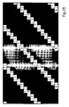
Ein wiederum anderes Beispiel für ein Filterarray im Sinne der Erfindung ist in Fig.13a gezeigt. Dieses Filterarray ist vorzugsweise mit einer Bildkombinationsvorschrift nach Fig.9 anzuwenden. Des besseren Verständnisses halber zeigt Fig.13b die schematische Zusammensetzung von transparenten Filterabschnitten aus mehreren transparenten Filtern bzw. Filterelementen. Das Filterarray in Fig.13b ist äquivalent zu dem Filterarray der Fig.13a. Diesbezüglich gibt die Fig.14 ein Beispiel der für ein Betrachterauge sichtbaren Bildelemente bzw. Bildelementteilflächen bei Zugrundelegung der Verhältnisse nach Fig.9 und Fig.13a wieder.Yet another example of a filter array according to the invention is shown in Fig. 13a. This filter array is preferably to be used with an image combination rule according to FIG. For a better understanding, FIG. 13b shows the schematic composition of transparent filter sections made up of a plurality of transparent filters or filter elements. The filter array in Fig. 13b is equivalent to the filter array of Fig. 13a. In this regard, FIG. 14 shows an example of the picture elements or picture element sub-areas that are visible to a viewer's eye on the basis of the relationships according to FIG. 9 and FIG.
Bei dem Filterarray nach Fig.13a bzw. Fig.13b ist im übrigen der Fall verwirklicht, daß auf mindestens einem der vorgesehenen Arrays aus Filterelementen in mindestens einer Zeile q des Arrays unmittelbar benachbarte Transparentfilter an eine andere Anzahl unmittelbar benachbart positionierter Transparentfilter auf der Zeile q-1 angrenzen, als auf der Zeile q+1. Beispielsweise in Zeile q=8 in Fig.13b wird ersichtlich, daß die gezeigten unmittelbar benachbarten vier Transparentfilter an vier unmittelbar benachbarte Transparentfilter der Zeile q+1=9 grenzen, während sie an nur ein Transparentfilter der vier unmittelbar benachbarten Transparentfilter der Zeile q-1=7 angrenzen.In the case of the filter array according to FIG. 13a or FIG. 13b, the case is realized that on at least one of the provided arrays of filter elements in at least one line q of the array immediately adjacent transparent filters to another number immediately adjacent positioned transparent filter on the line q -1, than on the
Weiterhin ist ein beispielhaftes Filterarray im Sinne der Erfindung in Fig.15 gezeigt. Dieses Filterarray ist ebenfalls vorzugsweise mit einer Bildkombinationsvorschrift nach Fig.9 anzuwenden.Furthermore, an exemplary filter array according to the invention in Fig.15 is shown. This filter array is likewise preferably to be used with an image combination rule according to FIG.
Fig.16 gibt ein Beispiel der für ein Betrachterauge sichtbaren Bildelemente bzw. Bildelementteilflächen bei Zugrundelegung der Verhältnisse nach Fig.9 und Fig.15 wieder.FIG. 16 shows an example of the picture elements or picture element sub-areas which are visible to a viewer's eye on the basis of the conditions according to FIG. 9 and FIG.
Bei dem Filterarray nach Fig.15 ist im übrigen ebenso der Fall verwirklicht, daß auf mindestens einem der vorgesehenen Arrays aus Wellenlängen- bzw. Graustufenfiltern in mindestens einer Zeile q des Arrays unmittelbar benachbarte Transparentfilter an eine andere Anzahl unmittelbar benachbart positionierter Transparentfilter auf der Zeile q-1 angrenzen, als auf der Zeile q+1.Incidentally, in the filter array of Fig. 15, the case is also realized that on at least one of the provided arrays of wavelength or grayscale filters in at least one line q of the array immediately adjacent transparent filters to another number immediately adjacent positioned transparent filter on the line q -1, than on the
Fig.17 zeigt ein Filterarray in einer weiteren Ausgestaltung der Erfindung, vorzugsweise anzuwenden mit einer Bildkombinationsvorschrift nach Fig.9, während Fig.18 ein Beispiel für mögliche für ein Betrachterauge sichtbare Bildelemente bzw. Bildelementteilflächen bei Zugrundelegung der Verhältnisse nach Fig.9 und Fig.17 wiedergibt.FIG. 17 shows a filter array in a further embodiment of the invention, preferably to be used with an image combination rule according to FIG. 9, while FIG. 18 shows an example of possible image elements or image element subareas visible to a viewer eye on the basis of the conditions according to Fig.9 and Fig.17 reproduces.
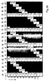
In Fig.19 ist ein weiteres Beispiel der Bildkombination und in Fig.20 ein in Verbindung mit der Bildkombinationsvorschrift nach Fig.19 für die räumliche Darstellung sehr gut geeignetes Filterarray nach der vorliegenden Erfindung zu sehen. Fig.21 und Fig.22 zeigen Beispiele für mögliche für die beiden Betrachteraugen sichtbaren Bildelemente bzw. Bildelementteilflächen bei Zugrundelegung der Verhältnisse nach Fig.19 und Fig.20. Es kommen hier acht Ansichten zur Darstellung, die jeweils auch in jeder Zeile dargestellt werden. Alternativ dazu könnten hier z.B. auch 40 Ansichten dargestellt werden, wobei pro Zeile vorzugsweise jeweils nur acht verschiedene Ansichten (z.B. 1, 6, 11, 16, 21, 26, 31, 36) verwendet werden. Die oben näher beschriebene Anzahl von pro Zeile zur Darstellung kommenden Ansichten n' wäre demnach auch hier n'=8.FIG. 19 shows a further example of the image combination and in FIG. 20 a filter array according to the present invention which is very well suited for the spatial representation in conjunction with the image combination rule according to FIG. FIGS. 21 and 22 show examples of possible picture elements or picture element sub-areas that are visible for the two observers, on the basis of the relationships according to FIGS. 19 and 20. Here are eight views for presentation, which are also shown in each row. Alternatively, here, e.g. 40 views are also shown, wherein preferably only eight different views are used per line (for example, 1, 6, 11, 16, 21, 26, 31, 36). The above-described number of views per line for display n 'would thus also be n' = 8.
Ein weiteres Beispiel der Ausgestaltung der Erfindung ist in den Fig.23 bis Fig.26 illustriert.Another example of the embodiment of the invention is illustrated in Figures 23 to 26.
Fig.23 zeigt das weitere Beispiel der Bildkombination, Fig.24 ein in Verbindung mit der Bildkombinationsvorschrift nach Fig.23 für die räumliche Darstellung sehr gut geeignetes Filterarray und die Fig.25 und Fig.26 stellen Beispiele für mögliche für die beiden Betrachteraugen sichtbaren Bildelemente bzw. Bildelementteilflächen bei Zugrundelegung der Verhältnisse nach Fig.23 und Fig.24 dar. Auch hier werden wieder acht Ansichten zur räumlichen Darstellung verwendet.23 shows the further example of the image combination, FIG. 24 shows a filter array very well suited for the spatial representation in conjunction with the image combination rule according to FIG. 23, and FIGS. 25 and 26 provide examples of possible image elements visible to the two observer eyes or picture element sub-areas on the basis of the conditions according to FIGS. 23 and 24. Again, eight views are used for the spatial representation.
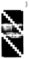
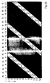
Eine dritte Variante der erfindungsgemäßen Anordnungen, bei denen mindestens ein erster von einem Rand des Arrays zu einem gegenüberliegenden Rand reichender und ununterbrochen durchgängiger Gürtel von Transparentfiltern und mindestens ein zweiter von einem Rand des Arrays zu einem gegenüberliegenden Rand reichender und ununterbrochen durchgängiger Gürtel von Transparentfiltern vorgesehen ist, wobei die Hauptausbreitungsrichtungen dieser beiden Gürtel auf dem Array nicht-parallel zueinander ausgerichtet sind, wird in den weiteren Zeichnungen detailliert erörtert werden.A third variant of the arrangements according to the invention, in which at least one first belt of transparent filters extending from one edge of the array to an opposite edge and continuously passing through is provided and at least one second belt of transparent filters extending from one edge of the array to an opposite edge and continuously passing through With the main propagation directions of these two belts on the array aligned non-parallel to each other, will be discussed in detail in the further drawings.
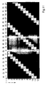
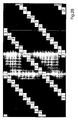
Hierzu gibt Fig.27 ein weiteres Beispiel der Bildkombination und Fig.28 ein dazu passendes Filterarray mit horizontalen Transparentfiltergürteln gemäß dieser Ausgestaltung der erfindungsgemäßen Anordnung wieder. Fig.29 und Fig.30 zeigen Beispiele für mögliche für die beiden Betrachteraugen sichtbaren Bildelemente bzw. Bildelementteilflächen bei Zugrundelegung der Verhältnisse nach Fig.27 und Fig.28.FIG. 27 shows a further example of the image combination and FIG. 28 a matching filter array with horizontal transparent filter belts according to this embodiment of the arrangement according to the invention. Figs. 29 and 30 show Examples of possible visible for the two observers picture elements or picture element sub-areas on the basis of the ratios according to Fig.27 and Fig.28.
Wie aus Fig.28 ersichtlich ist, sind hier beispielhaft horizontale Gürtel von Transparentfiltern vorgesehen. Demgegenüber sind weitere (stufenförmige, schräge) Gürtel jeweils vom unteren zum oberen Rand des Filterarrays vorgesehen, so daß die Hauptausbreitungsrichtungen der horizontalen und der schrägen Gürtel nicht-parallel zueinander liegen. In praxi enthält das Filterarray viel mehr Filterelemente; hier ist der Übersichtlichkeit geschuldet lediglich ein - willkürlich ausgeschnittener - Teil des Filterarrays dargestellt. So ist vorteilhaft insbesondere eine Vielzahl solcher durchgängigen Gürtel von Transparentfiltern vorgesehen. Wie in Fig.28 gezeigt, sind vorteilhaft einige oder alle durchgängige - horizontale - Gürtel von Transparentfiltern in periodischen Abständen zueinander auf dem Array angeordnet. Hier bildet beispielhaft jede vierte Zeile q (d.h. mit m=4) des Arrays einen derartigen durchgängigen horizontalen Gürtel von Transparentfiltern.As can be seen from FIG. 28, horizontal belts of transparent filters are provided by way of example here. On the other hand, other (stepped, oblique) belts are provided respectively from the lower to the upper edge of the filter array, so that the main propagation directions of the horizontal and oblique belts are non-parallel to each other. In practice, the filter array contains many more filter elements; For the sake of clarity, only one part of the filter array - cut out arbitrarily - is shown here. Thus, in particular, a plurality of such continuous belts of transparent filters is advantageously provided. As shown in Fig. 28, advantageously some or all of the continuous horizontal belts of transparent filters are arranged on the array at periodic intervals. Here, by way of example, every fourth row q (i.e., with m = 4) of the array forms such a continuous horizontal band of transparent filters.
Wie Fig.29 zeigt, sind in diesem Beispiel bei Parallelprojektion eines - aber nicht zwingend jedes - solchen durchgängigen - horizontalen - Gürtels von Transparentfiltern in Betrachtungsrichtung auf das Raster aus Bildelementen αij vorwiegend solche Bildelemente αij von Transparentfiltern mindestens teilweise überdeckt, die - in diesem Falle - ausschließlich Teilinformationen ein- und derselben Ansicht Ak wiedergeben.As shown in FIG. 29, in this example, in the case of parallel projection of such a continuous horizontal belt of transparent filters in the direction of observation onto the grid of picture elements α ij, predominantly those picture elements α ij of transparent filters are at least partially covered; In this case - reproduce only partial information of the same view A k .
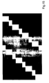
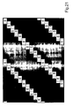
Im Rahmen der eben genannten Ausgestaltung der erfindungsgemäßen Anordnungen wird im folgenden ein weiteres Ausgestaltungsbeispiel gegeben. Es zeigt Fig.31 das entsprechende Beispiel der Bildkombination, Fig.32 ein dafür sehr gut geeignetes Filterarray mit unter anderem vertikalen Transparentfiltergürteln, sowie Fig.33 und Fig.34 Beispiele für mögliche für die beiden Betrachteraugen sichtbaren Bildelemente bzw. Bildelementteilflächen.In the context of the above-mentioned embodiment of the arrangements according to the invention, a further embodiment example is given below. FIG. 31 shows the corresponding example of the image combination, FIG. 32 shows a filter array which is very well suited for this purpose, inter alia vertical transparent filter belts, and FIGS. 33 and 34 show examples of possible image elements or picture element subareas visible to the two observer eyes.
Wie in Fig.32 zu sehen, sind hier zum eine schräge, zum anderen vertikale durchgängige Gürtel aus Transparentfiltern vorgesehen. Wie Fig.33 zeigt, sind in diesem Beispiel bei Parallelprojektion eines - aber nicht zwingend jedes - solchen durchgängigen - vertikalen - Gürtels von Transparentfiltern in Betrachtungsrichtung auf das Raster aus Bildelementen αij vorwiegend solche Bildelemente αij von Transparentfiltern mindestens teilweise überdeckt, die - in diesem Falle - überwiegend Teilinformationen ein- und derselben Ansicht Ak mit k=5 wiedergeben.As can be seen in FIG. 32, an oblique, on the other hand, vertical continuous belt of transparent filters are provided here. As shown in FIG. 33, in this example, in the case of parallel projection of such a continuous vertical belt of transparent filters in the direction of observation onto the grid of picture elements α ij, predominantly those picture elements α ij of transparent filters are at least partially covered; In this case - reproduce predominantly partial information of the same view A k with k = 5.
Die Fig.34 entspräche in etwa einer leicht versetzten Schrägsicht und nicht der Parallelprojektion in Betrachtungsrichtung (welche genau genommen in Richtung parallel zur Mittelsenkrechten auf dem Raster aus Bildelementen liegen würde), sondern eher einer Parallelprojektion in schräger Richtung.Fig. 34 would correspond approximately to a slightly offset oblique view and not parallel projection in the viewing direction (which, strictly speaking, would lie parallel to the perpendicular bisector on the pixel grid), but rather parallel projection in an oblique direction.
Entgegen den vorgenannten Ausführungen ist es jedoch auch denkbar, die Bildkombinationsvorschrift so zu gestalten, daß bei Parallelprojektion eines - aber nicht zwingend jedes - solchen durchgängigen Gürtels von Transparentfiltern in Betrachtungsrichtung auf das Raster aus Bildelementen αij mehrere solche Bildelemente αij von Transparentfiltern mindestens teilweise überdeckt sind, die Teilinformationen mindestens zweier verschiedener Ansichten Ak wiedergeben. Dabei sind verschiedene Variationen der entsprechenden mindestens zwei Ansichten Ak denkbar: Beispielsweise sind auch mehr als die geforderten zwei Ansichten verwendbar, z.B. n oder n-1 Ansichten. Auch kann die Bildkombinationsstruktur für die wie vorstehend beschrieben bei Parallelprojektion von Transparentfiltern mindestens teilweise überdeckten Bildelemente eine zufällige Struktur - und nicht wie bislang, wie z.B. in Fig.9 vorgestellt, ein periodische Struktur - aus Bildteilinformationen mehrerer Ansichten sein. Entscheidend für die Erzielung eines 3D-Eindruckes ist, daß der jeweilige Betrachter mit seinen Augen jeweils unterschiedliche Auswahlen aus Ansichten, d.h. Ansichtengemische, sieht.Contrary to the above-mentioned embodiments, however, it is also conceivable to design the image combination rule in such a way that parallel projection of at least partially covers such a continuous belt of transparent filters in the viewing direction onto the grid of picture elements α ij are the partial information of at least two different views A k play . Different variations of the corresponding at least two views A k are conceivable: For example, more than the required two views can also be used, for example n or n-1 views. The image combination structure for the image elements at least partially overlapped in the case of parallel projection of transparent filters as described above can also be a random structure-and not a picture structure of partial views-as was previously presented in FIG. Decisive for the achievement of a 3D impression is that the respective observer sees with his eyes in each case different selections from views, ie mixed views.
Ferner kann bei den vorgenannten Ausgestaltungen der erfindungsgemäßen Anordnungen die Breite der Transparentfiltergürtel variieren. Insbesondere bei den oben näher bezeichneten "schrägen" Gürteln kann die Breite der transparenten Filterabschnitte pro Zeile auch so gewählt werden, daß der Quotient aus der Gesamtfläche der Transparentfilter auf dem Array und der Gesamtfläche aller Filterelemente auf dem Array weniger als 1,1 /n' oder mehr als 1,8/n' beträgt.Furthermore, in the aforementioned embodiments of the arrangements according to the invention, the width of the transparent filter belts may vary. Particularly in the case of the "oblique" belts described in more detail above, the width of the transparent filter sections per line can also be selected such that the quotient of the total area of the transparent filters on the array and the total area of all filter elements on the array is less than 1.1 / n '. or more than 1.8 / n '.
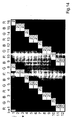
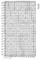
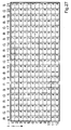
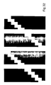
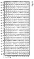
Fig.35 zeigt ein weiteres Filterarray, welches den Anforderungen der anfangs beschriebenen Ausgestaltungen der Erfindung gerecht werden kann, ergänzt um R'-, G'-, B'-Filter und ergänzt um Graustufenfilter. Mit R' sind hier rote, mit G' grüne und mit B' blaue Wellenlängenfilter gemeint. Die jeweiligen Filterelemente bedecken nur die umrissenen Flächenanteile. Mit L2 sind Graustufenfilter gemeint, die als Neutralfilter zur 50-prozentigen wellenlängenunabhängigen Schwächung der Lichtintensität ausgebildet sind. Diese und auch die R'-, G'- bzw. B'-Filter werden nicht in Betracht gezogen, wenn wie in den erfindungsgemäß charakteristischen Merkmalen von Filterelementen die Rede ist, die für Licht des im wesentlichen gesamten sichtbaren Spektrums weitestgehend oder im wesentlichen durchlässig sind. Die R'-, G'-, B'-Filter sind nämlich nur im jeweiligen roten, grünen bzw. blauen Wellenlängenbereich lichtdurchlässig und die L2-Filter schwächen die Lichtintensität nicht unwesentlich ab, so daß auch hier nicht von "weitestgehend durchlässig" oder "im wesentlichen" gesprochen werden kann.Fig. 35 shows another filter array which can meet the requirements of the initially described embodiments of the invention, supplemented by R ', G', B 'filters and supplemented by gray scale filters. By R 'here are meant red, with G' green and with B 'blue wavelength filters. The respective filter elements cover only the outlined area proportions. By L2 is meant grayscale filters, which are designed as neutral filters for 50 percent wavelength-independent attenuation of the light intensity. These and also the R ', G' and B 'filters are not considered if, as in the characteristic features of filter elements according to the invention the speech that is largely or substantially permeable to light of the substantially entire visible spectrum. The R'-, G'-, B'-filters are translucent only in the respective red, green or blue wavelength range and the L2 filters attenuate the light intensity not insignificantly, so that again not from "largely permeable" or " essentially "can be spoken.
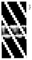
Eine weitere Ausgestaltung für ein Filterarray gemäß der anfangs beschriebenen Ausgestaltungen ist in Fig. 36 gezeigt. Während bei den oben beschriebenen Beispielen die nach vorne, zum Betrachter weisenden Flächen der Filterelemente βpq jeweils die Form von regelmäßigen Rechtecken hatten, werden in diesem Fall viele verschiedene Formen von Filterelementen βpq verwendet, so daß die schräg verlaufenden Streifen, die beispielsweise mit Transparentfiltern belegt sind, im wesentlichen glatte Kanten bekommen. Dies kann mit Hilfe der Figuren 37 und 38 verdeutlicht werden. Fig. 37 zeigt als Gitterstruktur das Array, auf dem die Filterelemente βpq angeordnet sind. Die einzelnen, verwendeten Filterelemente sind in Fig. 38 nebeneinander dargestellt. Die Zuordnung bzw. Kombination zu einem Maskenbild läßt sich analog mit der oben beschriebenen Formel für b bestimmen, wobei man jetzt allerdings mit jedem Wert von b eine der in Fig. 38 gezeigten Formen verbindet. In Fig. 39 und Fig. 40 sind Beispiele für jeweils das linke bzw. rechte Betrachterauge 3 gezeigt, d.h. welche Bildelemente mit welchen Ansichten diese von einer vorgegebenen Position des Betrachters aus sehen. Darüberhinaus ist es auch möglich, die Streifen nicht schräg, sondern senkrecht anzuordnen. Auch in diesem sowie dem folgenden Beispiel liegt der Quotient aus der Summe der Flächenanteile von Filterelementen βpq, die für Licht des im wesentlichen gesamten sichtbaren Spektrums weitestgehend durchlässig sind, und der Summe der Flächenanteile aller Filterelemente βpq zwischen 1,1 und 1,8.A further embodiment for a filter array according to the embodiments described initially is shown in FIG. While in the above-described examples, the front-to-viewer surfaces of the filter elements β pq each had the shape of regular rectangles, in this case, many different shapes of filter elements β pq are used, so that the oblique stripes formed with, for example, transparent filters are occupied, get essentially smooth edges. This can be clarified with the aid of FIGS. 37 and 38. FIG. 37 shows, as a lattice structure, the array on which the filter elements β pq are arranged. The individual filter elements used are shown side by side in FIG. The assignment or combination to a mask image can be determined analogously to the formula for b described above, but one now associates each of the values of b with one of the forms shown in FIG. FIGS. 39 and 40 show examples of the left and
Ein abschließendes Beispiel in Anlehnung an die eingangs genannten Ausführungsbeispiele wird in den Fig. 41-44 beschrieben. In Fig. 41 ist eine Bildkombination mit sechs Ansichten (n'=6) gezeigt; allerdings sind auch Kombinationen mit mehr oder weniger Ansichten möglich. Fig. 42 zeigt ein in Verbindung mit der Bildkombinationsvorschrift nach Fig. 41 für die räumliche Darstellung sehr gut geeignetes Filterarray, Fig. 43 und Fig. 44 zeigen beispielhaft, welche Bildelemente mit welchen Ansichten mit dem linken bzw. rechten Betrachterauge 3 von einer vorgegebenen Position des Betrachters aus sehen.A concluding example based on the aforementioned embodiments is described in FIGS. 41-44. In Fig. 41, an image combination with six views (n '= 6) is shown; however, combinations with more or less views are possible. 42 shows a filter array which is very well suited for the spatial representation in conjunction with the image combination specification according to FIG. 41; FIGS. 43 and 44 show, by way of example, which image elements with which views with the left and
In Fig. 42 sind gestrichelt die Abmessungen eines Transparentfilters eingezeichnet. Seine Breite entspricht etwa der eines Bildelements αij und beträgt beispielsweise 99,86% davon. Es ist außerdem etwa 1.5 mal so hoch; beispielsweise beträgt die Höhe 149,8% der Höhe eines Bildelements αij. Diese Verhältnisse treten beispielsweise bei einigen 18.1-Zoll-LC-Displays auf: Dort beträgt die mittlere Breite der Bildelemente 0,28047 mm und die mittlere Höhe 0,09349 mm. Ein Transparentfilterelement ist dann etwa 0,420146 mm hoch und 0,093366 mm breit.In Fig. 42 the dimensions of a transparent filter are shown in dashed lines. Its width corresponds approximately to that of a picture element α ij and is for example 99.86% thereof. It is also about 1.5 times as high; for example, the height is 149.8% of the height of a pixel α ij . These ratios occur, for example, in some 18.1-inch LC displays: There, the average width of the pixels is 0.28047 mm and the average height 0.09349 mm. A transparent filter element is then about 0.420146 mm high and 0.093366 mm wide.
Werden die einzelnen Transparentfilter im Filterarray nur halb so hoch ausgeführt, wie sie in Fig. 42 dargestellt sind, so läßt sich auch die Strukturierung über die Gleichung zur Bestimmung des Maskenbilds gemäß obiger Gleichung erreichen.If the individual transparent filters in the filter array are only half as high as those shown in FIG. 42, structuring can also be achieved via the equation for determining the mask image according to the above equation.
Die Erfindung bietet gegenüber dem Stand der Technik den Vorteil der Bildhelligkeitserhöhung bei der 3D-Darstellung. Damit einhergehend wird eine verbesserte Textlesbarkeit auf den erfindungsgemäßen Anordnungen gewährleistet.The invention offers the advantage over the prior art of increasing the image brightness in the 3D display. Along with this, improved text readability is ensured on the arrangements according to the invention.
Claims (23)
- An arrangement for the three dimensional display of a scenery or an object comprising- An image generator comprising a plurality of image elements (αij) arranged within a grid formed by rows (j) and columns (i), wherein partial information from at least three views (A k ) (k=1...n, n ≥ 3) of the scenery or the object is represented on the image elements (αij),- one or more arrays of a plurality of single filter elements (βpq) which are arranged in rows (q) and columns (p), wherein the filter elements (βpq) are implemented as wavelength and/ or grey level filters, a portion of which is implemented as translucent filters with respect to the whole visible spectrum, whereas the remaining portion (βpq) is non-translucent and is arranged; with respect to a direction of view; in front and / or behind the image generator comprising image elements (αij), such that directions of propagation are defined for the light emitted by the plurality of image elements (αij), wherein one image element (αij) corresponds to more than one filter elements (βpq) or one filter element corresponds to more than one of the image elements, respectively, the correspondence being such that a straight line between the centre of a visible portion of the image elements (αij) and the centre of a visible portion of the filter element (βpq), each, corresponds to a direction of propagation, wherein the directions of propagation intersect at a plurality of intersecting points within a viewing room in which the one or more viewers are located, each of the intersecting points corresponding to a viewing position, such that a viewer optically perceives, from each viewing position, with one eye mainly partial information from a first selection and with the second eye mainly partial information from a second selection out of the views (Ak) (k=1...n, n ≥3),characterized in that- on at least one of the arrays the ratio of the area portions of the filter elements being translucent over the whole visible spectrum to the total area of all filter elements multiplied by the average number(n') of different views displayed per line (j) of the grid formed by image elements (αij) is greater than 1 and not more than 2.
- The arrangement according to claim 1, characterized in that the ratio of the sum of the area portions of filter elements (βpq) which are substantially translucent over the whole visible spectrum, to the sum of all area portions of filter elements (βpq) of the respective array has a value in the range between ratio Q1=1.1/n' and ratio Q2=1.8/n', such that on average always about 1.1 to 1.8 image elements (αij) are visible per visible grid portion with respect to the image element area, due to the filter elements (βpq) which are translucent over the whole visible spectrum.
- The arrangement according to claim 1, characterized in that, for a parallel projection of a sufficiently large filter portion of at least one provided array formed by filter elements (βpq) onto at least a row (j) or onto at least a column (i) of the grid, at least the 1.1/n'-fold but not more than the 1. 8/n'-fold surface of the corresponding row (j), respectively the corresponding column (i) is covered by the filter elements (βpq) substantially being transparent over the whole visible spectrum; such that on average always about 1.1 to 1.8 image elements (αij) are visible per visible grid portion with respect to the image element area, due to the filter elements (βpq) which are translucent over the whole visible spectrum.
- The arrangement according to claim 1, characterized in that at least a first uninterrupted continuous belt of transparent filters that reaches from one edge of the array to the opposite edge, and at least a second uninterrupted continuous belt of transparent filters that reaches from one edge of the array to an opposite edge of the array is provided, wherein the main directions of extension of the two belts on the array are not arranged parallel to each other.
- The arrangement according to claim 4, characterized in that at least one of the provided continuous belts of transparent filters is arranged parallel to the upper, lower, left or right edge of the respective array formed of wavelength or grey level filters and/or parallel to the upper, lower, left or right edge of the grid of image elements (αij).
- The arrangement according to claim 4 or 5, characterized in that a plurality of such continuous belts of transparent filters is provided.
- The arrangement according to any one of the claims 4 to 6, characterized in that at least a portion of the continuous belts of transparent filters are arranged arbitrarily distributed over the array, provided said belts are parallel to each other.
- The arrangement according to any one of the claims 4 to 6 characterized in that at least a portion of the continuous belts of transparent filters is arranged on the array with a periodical distance to each other, as far as said belts are parallel to each other, wherein preferably each m-th cell (q) (m>1) of the corresponding array comprises such a continuous belt of transparent filters.
- The arrangement according to any one of claims 4 to 8, characterized in that for a parallel projection of one-but not necessarily each one - of such continuous belts of transparent filters, when viewed along a viewing direction facing the grid of image elements (αij), mostly such image elements (αij), that mostly or exclusively display partial information of one single view (Ak), are at least partly covered by transparent filters.
- The arrangement according to any one of claims 4 to 8, characterized in that for a parallel projection of one-but not necessarily each one-of such continuous belts of transparent filters, when viewed along a viewing direction facing the grid of image elements (αij), a plurality of such image elements (αij), that display partial information of at least two different views (Ak), are at least partly covered by transparent filters.
- The arrangement according to any one of the above claims, characterized in that the mapping of partial information belonging to views (Ak) (k=1...n) to image elements (αij) on the position (i,j) is done according to the following function
 - (i) denoting the index of an image element (αij) within a row of the grid,- (j) denoting the index of an image element (αij) within a column of the grid,- (k) denoting the running number of the view (Ak) (k=1...n), out of which the partial information is selected that is to be displayed within an image element (αij),- (n) being the total number of views (Ak) (k=1...n) present,- (cij) denoting a matrix of coefficients that can be chosen to combine respectively mix partial information belonging to different ones of the views (Ak) (k=1...n) of the grid and- IntegerPart denotes a function to generate the largest integer number that does not exceed the argument within the brackets.
 - The arrangement according to any one of the above claims, characterized in that, for the provided filter arrays, the filter elements (βpq) are combined to form a masking image depending on the filter element's wavelength of transparency / wave length range of transparency / the coefficient of transmission λb, according to the following formula:
 - (p) denoting the index of a filter element (βpq) within a row of the respective array,- (q) denoting the index of a filter element (βpq) within a column of the respective array,- (b) denoting an integer that indicates one value representing wave length of transparency/ wavelength range of transparency / coefficient of transmission λb, for a grey level filter element (βpq) at the position (p,q), wherein b is allowed to take values between 1 and (bmax) with bmax being an integer with bmax >1,- (nm) denoting an integer value greater than "Zero", which preferably corresponds to the total number (k) of views (Ak) displayed within the combined image,- (dpq) denoting a matrix of coefficients that can be chosen to vary the creation of a masking image and- IntegerPart denotes a function to produce the largest integer number that does not exceed the argument within the brackets.
 - The arrangement according to any one of the above claims, characterized in that exactly one array of filter elements (βpq) is provided and the distance (z) of the said array and the grid of image elements (αij), wherein the distance (z) is measured in perpendicular direction; is defined according to the following equation:
 - (sp) denotes the mean horizontal distance between neighbouring image elements (αij),- (pd) denotes the mean distance of pupils for a viewing person- (da) a viewing distance that can be selected.
 - The arrangement according to any one of the above claims characterized in that all filter elements provided with the filter array(s) are identical in size.
- The arrangement according to any one of the above claims characterized in that the filter elements provided with the at least one filter array are substantially arranged in a periodical arrangement.
- The arrangement according to any one of the above claims characterized in that the directions of propagation of light are given for the partial information displayed within the respective image elements (αij) according to their wave length /their range of wave length.
- The arrangement according to any one of the above claims characterized in that, within at least one of the provided arrays of filter elements (βpq) in at least one row (q) of the array, directly neighbouring filter elements are adjacent to a different number of directly neighbouringly positioned filter elements in row (q-1) than in row (q+1).
- The arrangement according to any one of the above claims characterized in that each one of the provided filter arrays is implemented as a static, non-time varying filter array and is further arranged in an essentially fixed relative position with respect to the grid of image elements (αij), hence the image generator.
- The arrangement according to any one of the above claims characterized in that at least one image element (αij) represents partial information of image information mixed from at least two different views (Ak).
- The arrangement according to any one of the above claims, characterized in that the image generator is selected from the group consisting of a liquid crystal (LC) display, a plasma screen or a screen comprising OLEDs.
- The arrangement according to any one of the above claims, wherein a translucent image display device, for example an LC-display as well as exactly one array of filter elements (βpq) is provided, which is located, in viewing direction, between the image display device and a planar illumination device, and wherein further a switchable scattering disc is provided between the image display device and the filter array, such that in a first operation mode, for which the switchable scattering disc is set transparent, a three dimensional impression for the viewer is caused, whereas within a second operation mode, wherein the switchable scattering disc is set, at least partially, scattering, the effect of the array of filter elements (βpq) is mostly lifted, such that the scattered light enables an essentially homogenous illumination of the image display device and two dimensional image information can perceptibly be displayed in full resolution.
- The arrangement according to any one of claims 1 to 20, wherein at least one array of filter elements (βpq) is provided, which comprises pixels acting at least partially as wave length filter respectively grey scale filter with an electrochromic or photochromic setup, wherein the array displays, in a first mode of operation for the 3D representation, in particular using the electrochromic or the photochromic pixel, a filter array structure suitable for the 3D representation, whereas in a second mode of operation the electrochromic or the photochromic pixels are set as transparent as possible, preferably essentially completely transparent over the whole visible spectrum.
- The arrangement according to claim 22, characterized in that wave length respectively grey scale filters are provided that are electrochromic respectively photochromic as well as unchangeable in their transmission characteristics, wherein said filters having unchangeable transmission characteristics are preferably implemented as essentially completely transparent over the whole visible spectrum.
Applications Claiming Priority (3)
| Application Number | Priority Date | Filing Date | Title |
|---|---|---|---|
| DE10309194 | 2003-02-26 | ||
| DE10309194A DE10309194B4 (en) | 2003-02-26 | 2003-02-26 | Method and arrangement for spatial representation |
| PCT/EP2004/001833 WO2004077839A1 (en) | 2003-02-26 | 2004-02-25 | Stereoscopic display method and arrangement |
Publications (2)
| Publication Number | Publication Date |
|---|---|
| EP1600007A1 EP1600007A1 (en) | 2005-11-30 |
| EP1600007B1 true EP1600007B1 (en) | 2007-12-19 |
Family
ID=32920657
Family Applications (1)
| Application Number | Title | Priority Date | Filing Date |
|---|---|---|---|
| EP04714289A Revoked EP1600007B1 (en) | 2003-02-26 | 2004-02-25 | Stereoscopic display arrangement |
Country Status (11)
| Country | Link |
|---|---|
| US (1) | US8169381B2 (en) |
| EP (1) | EP1600007B1 (en) |
| JP (1) | JP4023626B2 (en) |
| KR (1) | KR20050086454A (en) |
| CN (1) | CN1754392A (en) |
| AT (1) | ATE381856T1 (en) |
| AU (1) | AU2004214741A1 (en) |
| CA (1) | CA2516928A1 (en) |
| DE (2) | DE10309194B4 (en) |
| RU (1) | RU2323542C2 (en) |
| WO (1) | WO2004077839A1 (en) |
Cited By (1)
| Publication number | Priority date | Publication date | Assignee | Title |
|---|---|---|---|---|
| WO2011131743A1 (en) | 2010-04-23 | 2011-10-27 | Tridelity Ag | Simultaneous reproduction of a plurality of images by means of a two-dimensional imaging matrix |
Families Citing this family (57)
| Publication number | Priority date | Publication date | Assignee | Title |
|---|---|---|---|---|
| DE10145133C1 (en) * | 2001-09-06 | 2003-04-30 | 4D Vision Gmbh | Spatial representation method |
| WO2004057878A2 (en) * | 2002-12-20 | 2004-07-08 | X3D Technologies Gmbh | Arrangement for two-dimensional or three-dimensional representation |
| DE102005017313A1 (en) | 2005-04-14 | 2006-10-19 | Volkswagen Ag | Method for displaying information in a means of transport and instrument cluster for a motor vehicle |
| DE102005020152A1 (en) | 2005-04-29 | 2006-11-02 | Volkswagen Ag | Method for controlling map display in vehicle involves display device which is controlled in such manner that section of geographical map is displayed in three-dimensionally non-linear scale |
| DE102005020151A1 (en) | 2005-04-29 | 2006-11-02 | Volkswagen Ag | Geographical map display device controlling method for motor vehicle`s navigation system, involves evaluating relevance of units e.g. restaurants, displayed on map for user, and automatically deciding which units are displayed at positions |
| DE602006009294D1 (en) * | 2005-11-09 | 2009-10-29 | Koninkl Philips Electronics Nv | DISPLAY DEVICE WITH HOMOGENIZING DAMPING FILTER |
| KR101210887B1 (en) * | 2005-12-22 | 2012-12-11 | 엘지디스플레이 주식회사 | Liquid Crystal Display Device and Driving Method Thereof |
| DE102006013407A1 (en) * | 2006-03-20 | 2007-09-27 | Newsight Gmbh | Arrangement for optionally three-dimensionally perceptible or two-dimensional representation of images |
| WO2007107347A1 (en) * | 2006-03-21 | 2007-09-27 | Newsight Gmbh | Arrangement for spatially perceptible display |
| DE102006014724B4 (en) | 2006-03-30 | 2023-06-29 | Volkswagen Ag | Information system for occupants of a motor vehicle |
| DE102006024615B4 (en) | 2006-05-26 | 2018-08-09 | Volkswagen Ag | Method for selecting and displaying a visual representation for an operating function of a control device in a vehicle and operating device |
| DE102006032117A1 (en) * | 2006-07-12 | 2008-01-24 | Volkswagen Ag | Information system for transport medium, particularly motor vehicles, has input unit and indicator with display, where input unit has device to record position of object before display with in transport medium |
| JP5121198B2 (en) * | 2006-09-22 | 2013-01-16 | 独立行政法人物質・材料研究機構 | Image output device and parallel analog computing device using light transmission filter |
| DE102007016773B4 (en) * | 2007-04-04 | 2011-12-22 | Wise Vision Holdings Ltd. | Method and arrangement for three-dimensional representation |
| DE102007026628B3 (en) | 2007-06-07 | 2008-08-14 | Visumotion Gmbh | Parallax barrier screen adjusting method for industrial application, involves adjusting barrier screen to display screen such that adjustment of barrier screen to display screen with pixels is defined with preset tolerance of pixels |
| DE102007039079B4 (en) | 2007-08-16 | 2011-07-21 | VisuMotion GmbH, 07745 | Method and arrangement for the spatial representation of a scene with little or no illumination |
| DE102007045385B3 (en) * | 2007-09-20 | 2009-04-23 | Visumotion Gmbh | A method for shortening or extending a viewing distance between the viewer and an arrangement for spatially perceptible presentation |
| DE102007047470B3 (en) * | 2007-09-28 | 2009-05-28 | Visumotion Gmbh | Method for aligning a parallax barrier screen on a screen |
| DE102007054011B4 (en) * | 2007-11-09 | 2012-06-14 | Visumotion Gmbh | Method and arrangement for spatial representation |
| US20090128900A1 (en) * | 2007-11-15 | 2009-05-21 | Idyllic Spectrum Sdn Bhd | Autostereoscopic display |
| DE102008007727A1 (en) * | 2008-02-05 | 2009-08-13 | Visumotion Gmbh | Method and arrangement for spatial representation with color-sequential illumination |
| JP2009230635A (en) * | 2008-03-25 | 2009-10-08 | Olympus Imaging Corp | Image data generating device, image data generating method and image data generating program |
| DE102008017051B4 (en) | 2008-04-03 | 2023-12-28 | Volkswagen Ag | Method for controlling an air conditioning system of a vehicle and operating device for an air conditioning system |
| DE102009010830A1 (en) | 2008-04-28 | 2009-10-29 | Volkswagen Ag | Method for stereoscopically displaying e.g. information in display of LCD of motor vehicle, involves positioning rotating wheel depending on position of objects, and adjusting another object for selecting rotating wheel |
| CN103501431A (en) | 2008-07-15 | 2014-01-08 | 株式会社Ip舍路信 | Naked eye three-dimensional video image display system, naked eye three-dimensional video image display device, amusement game machine and parallax barrier sheet |
| DE102008050803A1 (en) | 2008-10-08 | 2010-04-15 | Volkswagen Ag | Method and device for displaying information in a vehicle |
| DE102008061988A1 (en) | 2008-12-12 | 2010-06-17 | Volkswagen Ag | Method and device for displaying information |
| JP5726087B2 (en) * | 2009-11-12 | 2015-05-27 | ネプラス株式会社 | Parallax barrier filter |
| US9659353B2 (en) * | 2010-03-01 | 2017-05-23 | Stmicroelectronics, Inc. | Object speed weighted motion compensated interpolation |
| JP2011216701A (en) * | 2010-03-31 | 2011-10-27 | Sony Corp | Solid-state imaging apparatus and electronic device |
| DE102010022613A1 (en) | 2010-06-01 | 2011-12-01 | Visumotion Gmbh | Method and arrangement for spatial representation |
| US20110304909A1 (en) * | 2010-06-10 | 2011-12-15 | Industrial Technology Research Institute | Image display |
| KR101174076B1 (en) * | 2010-08-31 | 2012-08-16 | 유한회사 마스터이미지쓰리디아시아 | Auto stereoscopic Display Apparatus Using Diagonal Direction Parallax Barrier |
| JP2012053342A (en) * | 2010-09-02 | 2012-03-15 | Sony Corp | Display apparatus |
| JP2012053344A (en) | 2010-09-02 | 2012-03-15 | Sony Corp | Display apparatus |
| JP5664031B2 (en) | 2010-09-02 | 2015-02-04 | ソニー株式会社 | Display device |
| EP2437098A1 (en) | 2010-10-01 | 2012-04-04 | 3D Impact Media | Auto stereoscopic display assembly |
| DE102010052291B4 (en) | 2010-11-23 | 2021-11-25 | Volkswagen Ag | Method and device for displaying information in a vehicle |
| CN102081238B (en) * | 2010-12-17 | 2013-04-24 | 电子科技大学 | Optically controlled grating type free and stereo display device and preparation method thereof |
| JP2012155307A (en) * | 2011-01-05 | 2012-08-16 | Sony Mobile Display Corp | Display device |
| JP6147953B2 (en) | 2011-03-15 | 2017-06-14 | 株式会社ジャパンディスプレイ | Display device |
| EP2703874B1 (en) * | 2011-04-28 | 2019-09-18 | Panasonic Intellectual Property Corporation of America | Video display device |
| WO2013042332A1 (en) * | 2011-09-20 | 2013-03-28 | パナソニック株式会社 | Video display method, video display panel, and video display apparatus |
| US9022564B2 (en) * | 2011-12-21 | 2015-05-05 | Panasonic Intellectual Property Corporation Of America | Display apparatus |
| JP5806150B2 (en) * | 2012-03-13 | 2015-11-10 | 株式会社ジャパンディスプレイ | Display device |
| JP5806156B2 (en) * | 2012-03-23 | 2015-11-10 | 株式会社ジャパンディスプレイ | Display device, electronic device |
| JP5351311B1 (en) | 2012-06-29 | 2013-11-27 | 株式会社ソニー・コンピュータエンタテインメント | Stereoscopic image observation device and transmittance control method |
| DE102012018191B4 (en) | 2012-09-10 | 2021-09-30 | Global 3D Media Holding Co., Ltd. | Procedure and arrangement for spatial representation |
| US20160027391A1 (en) * | 2013-03-19 | 2016-01-28 | Hewlett-Packard Development Company, Lp | Dual-sided display |
| EP3090302B1 (en) | 2014-01-02 | 2021-07-07 | Wolfgang Tzschoppe | Method and apparatus for an autoparallactic and autostereoscopic display |
| DE102014000082A1 (en) | 2014-01-02 | 2015-07-02 | Wolfgang Tzschoppe | Method and arrangement for autoparallactic display |
| DE102014206049A1 (en) | 2014-03-31 | 2015-10-01 | Volkswagen Aktiengesellschaft | Method for displaying information in a vehicle |
| CN105138164B (en) * | 2015-07-31 | 2018-12-11 | 业成光电(深圳)有限公司 | Naked eye three-dimensional shows touch-control module |
| CN105185812B (en) * | 2015-09-08 | 2017-12-22 | 京东方科技集团股份有限公司 | OLED pixel structure, display base plate and display device |
| DE102016202431A1 (en) * | 2016-02-17 | 2017-08-31 | Fraunhofer-Gesellschaft zur Förderung der angewandten Forschung e.V. | Autostereoscopic screen and its use for reproducing three-dimensionally perceptible images |
| CN105842858A (en) * | 2016-06-12 | 2016-08-10 | 武汉华星光电技术有限公司 | Light splitter and stereoscopic display panel |
| CN112103317B (en) * | 2020-09-15 | 2024-04-09 | 视涯科技股份有限公司 | Organic light-emitting display panel and display device |
Family Cites Families (27)
| Publication number | Priority date | Publication date | Assignee | Title |
|---|---|---|---|---|
| JP2902957B2 (en) | 1994-02-25 | 1999-06-07 | 三洋電機株式会社 | 3D display device |
| US6184969B1 (en) | 1994-10-25 | 2001-02-06 | James L. Fergason | Optical display system and method, active and passive dithering using birefringence, color image superpositioning and display enhancement |
| JP2951235B2 (en) | 1994-11-18 | 1999-09-20 | 三洋電機株式会社 | Liquid crystal display |
| JP3096613B2 (en) | 1995-05-30 | 2000-10-10 | 三洋電機株式会社 | 3D display device |
| US6023315A (en) | 1995-07-04 | 2000-02-08 | Sharp Kabushiki Kaisha | Spatial light modulator and directional display |
| GB9513658D0 (en) | 1995-07-05 | 1995-09-06 | Philips Electronics Uk Ltd | Autostereoscopic display apparatus |
| US5936774A (en) | 1995-08-29 | 1999-08-10 | Street; Graham S. B. | Autostereoscopic display |
| US20020030888A1 (en) * | 1996-10-16 | 2002-03-14 | Paul Kleinberger | Systems for three-dimensional viewing and projection |
| US6064424A (en) | 1996-02-23 | 2000-05-16 | U.S. Philips Corporation | Autostereoscopic display apparatus |
| US6459425B1 (en) | 1997-08-25 | 2002-10-01 | Richard A. Holub | System for automatic color calibration |
| US6137456A (en) * | 1996-07-01 | 2000-10-24 | Corning Incorporated | Electronic display device for simultaneously displaying 2D and 3D images |
| JP4083829B2 (en) | 1996-07-15 | 2008-04-30 | 富士通株式会社 | Stereoscopic image display device |
| GB9617314D0 (en) | 1996-08-17 | 1996-09-25 | Fryco Ltd | Optical images |
| JP2000098299A (en) | 1998-09-18 | 2000-04-07 | Sanyo Electric Co Ltd | Stereoscopic video display device |
| US6157041A (en) | 1998-10-13 | 2000-12-05 | Rio Grande Medical Technologies, Inc. | Methods and apparatus for tailoring spectroscopic calibration models |
| JP2001211465A (en) | 1999-11-15 | 2001-08-03 | Hit Design:Kk | Three-dimensional image display method and three- dimensional image display device using the method |
| US6452595B1 (en) | 1999-12-06 | 2002-09-17 | Nvidia Corporation | Integrated graphics processing unit with antialiasing |
| DE20022583U1 (en) * | 2000-01-25 | 2001-12-20 | 4D Vision Gmbh | Arrangement for spatial representation |
| CA2436596C (en) * | 2000-01-25 | 2005-10-25 | 4D-Vision Gmbh | Method and arrangement for the three-dimensional display |
| DE20121581U1 (en) * | 2000-01-25 | 2003-04-03 | 4D Vision Gmbh | Arrangement for three-dimensional representation |
| DE10003326C2 (en) | 2000-01-25 | 2002-04-18 | 4D Vision Gmbh | Method and arrangement for spatial representation |
| DE10145133C1 (en) | 2001-09-06 | 2003-04-30 | 4D Vision Gmbh | Spatial representation method |
| DE20211612U1 (en) | 2002-07-12 | 2002-10-10 | 4D Vision Gmbh | Autostereoscopic projection arrangement |
| JP2005533291A (en) | 2002-07-12 | 2005-11-04 | イクスドライデー テヒノロギーズ ゲーエムベーハー | Autostereoscopic projection device |
| DE10241475A1 (en) | 2002-09-03 | 2004-03-11 | 4D-Vision Gmbh | simulation methods |
| WO2004043079A1 (en) | 2002-11-07 | 2004-05-21 | Sanyo Electric Co., Ltd. | Three-dimensional video processing method and three-dimensional video display |
| JP3897712B2 (en) | 2003-02-14 | 2007-03-28 | キヤノン株式会社 | Stereoscopic image display device |
-
2003
- 2003-02-26 DE DE10309194A patent/DE10309194B4/en not_active Expired - Fee Related
-
2004
- 2004-02-25 RU RU2005129545/09A patent/RU2323542C2/en not_active IP Right Cessation
- 2004-02-25 CA CA002516928A patent/CA2516928A1/en not_active Abandoned
- 2004-02-25 AT AT04714289T patent/ATE381856T1/en not_active IP Right Cessation
- 2004-02-25 WO PCT/EP2004/001833 patent/WO2004077839A1/en active IP Right Grant
- 2004-02-25 KR KR1020057008238A patent/KR20050086454A/en not_active Application Discontinuation
- 2004-02-25 EP EP04714289A patent/EP1600007B1/en not_active Revoked
- 2004-02-25 DE DE502004005752T patent/DE502004005752D1/en not_active Expired - Lifetime
- 2004-02-25 US US10/532,479 patent/US8169381B2/en not_active Expired - Fee Related
- 2004-02-25 CN CNA2004800052123A patent/CN1754392A/en active Pending
- 2004-02-25 JP JP2005518160A patent/JP4023626B2/en not_active Expired - Fee Related
- 2004-02-25 AU AU2004214741A patent/AU2004214741A1/en not_active Abandoned
Cited By (3)
| Publication number | Priority date | Publication date | Assignee | Title |
|---|---|---|---|---|
| WO2011131743A1 (en) | 2010-04-23 | 2011-10-27 | Tridelity Ag | Simultaneous reproduction of a plurality of images by means of a two-dimensional imaging matrix |
| DE102010018083A1 (en) * | 2010-04-23 | 2011-10-27 | Tridelity Ag | Simultaneous reproduction of a plurality of images by means of a two-dimensional image representation matrix |
| DE102010018083B4 (en) * | 2010-04-23 | 2013-05-08 | Tridelity Ag | Simultaneous reproduction of a plurality of images by means of a two-dimensional image representation matrix |
Also Published As
| Publication number | Publication date |
|---|---|
| AU2004214741A1 (en) | 2004-09-10 |
| CN1754392A (en) | 2006-03-29 |
| RU2005129545A (en) | 2007-04-10 |
| WO2004077839A1 (en) | 2004-09-10 |
| US8169381B2 (en) | 2012-05-01 |
| DE502004005752D1 (en) | 2008-01-31 |
| KR20050086454A (en) | 2005-08-30 |
| US20050280602A1 (en) | 2005-12-22 |
| ATE381856T1 (en) | 2008-01-15 |
| DE10309194A1 (en) | 2004-10-14 |
| CA2516928A1 (en) | 2004-09-10 |
| JP2006515934A (en) | 2006-06-08 |
| RU2323542C2 (en) | 2008-04-27 |
| DE10309194B4 (en) | 2008-10-09 |
| JP4023626B2 (en) | 2007-12-19 |
| EP1600007A1 (en) | 2005-11-30 |
Similar Documents
| Publication | Publication Date | Title |
|---|---|---|
| EP1600007B1 (en) | Stereoscopic display arrangement | |
| DE10003326C2 (en) | Method and arrangement for spatial representation | |
| DE10145133C1 (en) | Spatial representation method | |
| EP1574078A2 (en) | Arrangement for two-dimensional or three-dimensional representation | |
| WO2004098203A1 (en) | Arrangement for realizing a three-dimensional representation | |
| DE112008002241T5 (en) | High-resolution display of 3D images | |
| DE102009009443B3 (en) | Monitor and method for displaying autostereoscopic images | |
| EP0937274B1 (en) | Stereo hologram display (holdisp) | |
| EP1683366A1 (en) | Two-dimensional or three-dimensional representation array | |
| EP1895782A2 (en) | Auto stereoscopic display device | |
| DE102007046414B4 (en) | Methods and arrangements for spatial representation | |
| WO2004023348A1 (en) | Method for simulating optical components for the stereoscopic production of spatial impressions | |
| WO2006029716A1 (en) | Assembly for the selective three-dimensional or two-dimensional representation of images | |
| DE102010018083B4 (en) | Simultaneous reproduction of a plurality of images by means of a two-dimensional image representation matrix | |
| DE102010021550B4 (en) | Image display device and method for image reproduction | |
| DE102007054011B4 (en) | Method and arrangement for spatial representation | |
| DE102004051355A1 (en) | Arrangement for spatially perceptible representation | |
| EP3767946A1 (en) | Base display for an autostereoscopic display assembly | |
| EP1665816A1 (en) | Method and arrangement for three-dimensionally recognizable representation | |
| WO2004107019A1 (en) | Spatial representation assembly | |
| DE10118461C2 (en) | Method and arrangement for displaying a multidimensional image | |
| DE102005006249A1 (en) | Two or three dimensional image representing arrangement for electronically controllable color liquid crystal display panel, has image replication unit with pixels, where average of fully colored pixels are made visible to each eye of viewer | |
| DE10029584A1 (en) | Three-dimensional image representation method uses grid of individual image elements representing partial information for scene/object from different directions | |
| DE10317614A1 (en) | Image representation arrangement selectively providing 2-dimensional or 3-dimensional image of scene or object | |
| DE20023958U1 (en) | Arrangement for spatial representation using neutral filters |
Legal Events
| Date | Code | Title | Description |
|---|---|---|---|
| PUAI | Public reference made under article 153(3) epc to a published international application that has entered the european phase |
Free format text: ORIGINAL CODE: 0009012 |
|
| 17P | Request for examination filed |
Effective date: 20050407 |
|
| AK | Designated contracting states |
Kind code of ref document: A1 Designated state(s): AT BE BG CH CY CZ DE DK EE ES FI FR GB GR HU IE IT LI LU MC NL PT RO SE SI SK TR |
|
| AX | Request for extension of the european patent |
Extension state: AL LT LV MK |
|
| DAX | Request for extension of the european patent (deleted) | ||
| GRAP | Despatch of communication of intention to grant a patent |
Free format text: ORIGINAL CODE: EPIDOSNIGR1 |
|
| RTI1 | Title (correction) |
Free format text: STEREOSCOPIC DISPLAY ARRANGEMENT |
|
| GRAS | Grant fee paid |
Free format text: ORIGINAL CODE: EPIDOSNIGR3 |
|
| GRAA | (expected) grant |
Free format text: ORIGINAL CODE: 0009210 |
|
| TPAC | Observations filed by third parties |
Free format text: ORIGINAL CODE: EPIDOSNTIPA |
|
| AK | Designated contracting states |
Kind code of ref document: B1 Designated state(s): AT BE BG CH CY CZ DE DK EE ES FI FR GB GR HU IE IT LI LU MC NL PT RO SE SI SK TR |
|
| REG | Reference to a national code |
Ref country code: GB Ref legal event code: FG4D Free format text: NOT ENGLISH |
|
| REG | Reference to a national code |
Ref country code: IE Ref legal event code: FG4D Free format text: LANGUAGE OF EP DOCUMENT: GERMAN |
|
| REG | Reference to a national code |
Ref country code: CH Ref legal event code: EP |
|
| REF | Corresponds to: |
Ref document number: 502004005752 Country of ref document: DE Date of ref document: 20080131 Kind code of ref document: P |
|
| REG | Reference to a national code |
Ref country code: GR Ref legal event code: EP Ref document number: 20080400768 Country of ref document: GR |
|
| PG25 | Lapsed in a contracting state [announced via postgrant information from national office to epo] |
Ref country code: SE Free format text: LAPSE BECAUSE OF FAILURE TO SUBMIT A TRANSLATION OF THE DESCRIPTION OR TO PAY THE FEE WITHIN THE PRESCRIBED TIME-LIMIT Effective date: 20080319 |
|
| PG25 | Lapsed in a contracting state [announced via postgrant information from national office to epo] |
Ref country code: FI Free format text: LAPSE BECAUSE OF FAILURE TO SUBMIT A TRANSLATION OF THE DESCRIPTION OR TO PAY THE FEE WITHIN THE PRESCRIBED TIME-LIMIT Effective date: 20071219 Ref country code: SI Free format text: LAPSE BECAUSE OF FAILURE TO SUBMIT A TRANSLATION OF THE DESCRIPTION OR TO PAY THE FEE WITHIN THE PRESCRIBED TIME-LIMIT Effective date: 20071219 |
|
| PGFP | Annual fee paid to national office [announced via postgrant information from national office to epo] |
Ref country code: AT Payment date: 20080331 Year of fee payment: 5 |
|
| PG25 | Lapsed in a contracting state [announced via postgrant information from national office to epo] |
Ref country code: CZ Free format text: LAPSE BECAUSE OF FAILURE TO SUBMIT A TRANSLATION OF THE DESCRIPTION OR TO PAY THE FEE WITHIN THE PRESCRIBED TIME-LIMIT Effective date: 20071219 Ref country code: ES Free format text: LAPSE BECAUSE OF FAILURE TO SUBMIT A TRANSLATION OF THE DESCRIPTION OR TO PAY THE FEE WITHIN THE PRESCRIBED TIME-LIMIT Effective date: 20080330 |
|
| ET | Fr: translation filed | ||
| PG25 | Lapsed in a contracting state [announced via postgrant information from national office to epo] |
Ref country code: SK Free format text: LAPSE BECAUSE OF FAILURE TO SUBMIT A TRANSLATION OF THE DESCRIPTION OR TO PAY THE FEE WITHIN THE PRESCRIBED TIME-LIMIT Effective date: 20071219 Ref country code: RO Free format text: LAPSE BECAUSE OF FAILURE TO SUBMIT A TRANSLATION OF THE DESCRIPTION OR TO PAY THE FEE WITHIN THE PRESCRIBED TIME-LIMIT Effective date: 20071219 |
|
| BERE | Be: lapsed |
Owner name: X3D TECHNOLOGIES G.M.B.H. Effective date: 20080228 |
|
| PLBI | Opposition filed |
Free format text: ORIGINAL CODE: 0009260 |
|
| PG25 | Lapsed in a contracting state [announced via postgrant information from national office to epo] |
Ref country code: PT Free format text: LAPSE BECAUSE OF FAILURE TO SUBMIT A TRANSLATION OF THE DESCRIPTION OR TO PAY THE FEE WITHIN THE PRESCRIBED TIME-LIMIT Effective date: 20080519 |
|
| PGFP | Annual fee paid to national office [announced via postgrant information from national office to epo] |
Ref country code: IT Payment date: 20080529 Year of fee payment: 5 |
|
| REG | Reference to a national code |
Ref country code: CH Ref legal event code: PL |
|
| REG | Reference to a national code |
Ref country code: IE Ref legal event code: FD4D |
|
| PLAX | Notice of opposition and request to file observation + time limit sent |
Free format text: ORIGINAL CODE: EPIDOSNOBS2 |
|
| 26 | Opposition filed |
Opponent name: VISUMOTION GMBH Effective date: 20080919 |
|
| PG25 | Lapsed in a contracting state [announced via postgrant information from national office to epo] |
Ref country code: IE Free format text: LAPSE BECAUSE OF FAILURE TO SUBMIT A TRANSLATION OF THE DESCRIPTION OR TO PAY THE FEE WITHIN THE PRESCRIBED TIME-LIMIT Effective date: 20071219 Ref country code: LI Free format text: LAPSE BECAUSE OF NON-PAYMENT OF DUE FEES Effective date: 20080229 Ref country code: DK Free format text: LAPSE BECAUSE OF FAILURE TO SUBMIT A TRANSLATION OF THE DESCRIPTION OR TO PAY THE FEE WITHIN THE PRESCRIBED TIME-LIMIT Effective date: 20071219 Ref country code: CH Free format text: LAPSE BECAUSE OF NON-PAYMENT OF DUE FEES Effective date: 20080229 Ref country code: MC Free format text: LAPSE BECAUSE OF NON-PAYMENT OF DUE FEES Effective date: 20080228 |
|
| PGFP | Annual fee paid to national office [announced via postgrant information from national office to epo] |
Ref country code: NL Payment date: 20080724 Year of fee payment: 5 |
|
| NLR1 | Nl: opposition has been filed with the epo |
Opponent name: VISUMOTION GMBH |
|
| PG25 | Lapsed in a contracting state [announced via postgrant information from national office to epo] |
Ref country code: EE Free format text: LAPSE BECAUSE OF FAILURE TO SUBMIT A TRANSLATION OF THE DESCRIPTION OR TO PAY THE FEE WITHIN THE PRESCRIBED TIME-LIMIT Effective date: 20071219 |
|
| PLAF | Information modified related to communication of a notice of opposition and request to file observations + time limit |
Free format text: ORIGINAL CODE: EPIDOSCOBS2 |
|
| PG25 | Lapsed in a contracting state [announced via postgrant information from national office to epo] |
Ref country code: BE Free format text: LAPSE BECAUSE OF NON-PAYMENT OF DUE FEES Effective date: 20080228 |
|
| PG25 | Lapsed in a contracting state [announced via postgrant information from national office to epo] |
Ref country code: BG Free format text: LAPSE BECAUSE OF FAILURE TO SUBMIT A TRANSLATION OF THE DESCRIPTION OR TO PAY THE FEE WITHIN THE PRESCRIBED TIME-LIMIT Effective date: 20080319 |
|
| PLBB | Reply of patent proprietor to notice(s) of opposition received |
Free format text: ORIGINAL CODE: EPIDOSNOBS3 |
|
| PGFP | Annual fee paid to national office [announced via postgrant information from national office to epo] |
Ref country code: GR Payment date: 20080530 Year of fee payment: 5 |
|
| PG25 | Lapsed in a contracting state [announced via postgrant information from national office to epo] |
Ref country code: CY Free format text: LAPSE BECAUSE OF FAILURE TO SUBMIT A TRANSLATION OF THE DESCRIPTION OR TO PAY THE FEE WITHIN THE PRESCRIBED TIME-LIMIT Effective date: 20071219 |
|
| PG25 | Lapsed in a contracting state [announced via postgrant information from national office to epo] |
Ref country code: AT Free format text: LAPSE BECAUSE OF NON-PAYMENT OF DUE FEES Effective date: 20090225 |
|
| NLV4 | Nl: lapsed or anulled due to non-payment of the annual fee |
Effective date: 20090901 |
|
| PG25 | Lapsed in a contracting state [announced via postgrant information from national office to epo] |
Ref country code: NL Free format text: LAPSE BECAUSE OF NON-PAYMENT OF DUE FEES Effective date: 20090901 |
|
| PG25 | Lapsed in a contracting state [announced via postgrant information from national office to epo] |
Ref country code: GR Free format text: LAPSE BECAUSE OF NON-PAYMENT OF DUE FEES Effective date: 20090902 |
|
| PG25 | Lapsed in a contracting state [announced via postgrant information from national office to epo] |
Ref country code: LU Free format text: LAPSE BECAUSE OF NON-PAYMENT OF DUE FEES Effective date: 20080225 Ref country code: HU Free format text: LAPSE BECAUSE OF FAILURE TO SUBMIT A TRANSLATION OF THE DESCRIPTION OR TO PAY THE FEE WITHIN THE PRESCRIBED TIME-LIMIT Effective date: 20080620 |
|
| PG25 | Lapsed in a contracting state [announced via postgrant information from national office to epo] |
Ref country code: TR Free format text: LAPSE BECAUSE OF FAILURE TO SUBMIT A TRANSLATION OF THE DESCRIPTION OR TO PAY THE FEE WITHIN THE PRESCRIBED TIME-LIMIT Effective date: 20071219 |
|
| RDAF | Communication despatched that patent is revoked |
Free format text: ORIGINAL CODE: EPIDOSNREV1 |
|
| PG25 | Lapsed in a contracting state [announced via postgrant information from national office to epo] |
Ref country code: IT Free format text: LAPSE BECAUSE OF NON-PAYMENT OF DUE FEES Effective date: 20090225 |
|
| RDAG | Patent revoked |
Free format text: ORIGINAL CODE: 0009271 |
|
| STAA | Information on the status of an ep patent application or granted ep patent |
Free format text: STATUS: PATENT REVOKED |
|
| PGFP | Annual fee paid to national office [announced via postgrant information from national office to epo] |
Ref country code: FR Payment date: 20110316 Year of fee payment: 8 |
|
| 27W | Patent revoked |
Effective date: 20110120 |
|
| GBPR | Gb: patent revoked under art. 102 of the ep convention designating the uk as contracting state |
Effective date: 20110120 |
|
| PGFP | Annual fee paid to national office [announced via postgrant information from national office to epo] |
Ref country code: GB Payment date: 20110303 Year of fee payment: 8 Ref country code: DE Payment date: 20110426 Year of fee payment: 8 |