EP1599676B1 - Membrandruckerzeugerdeckel mit luftkanäle - Google Patents
Membrandruckerzeugerdeckel mit luftkanäle Download PDFInfo
- Publication number
- EP1599676B1 EP1599676B1 EP04704002.7A EP04704002A EP1599676B1 EP 1599676 B1 EP1599676 B1 EP 1599676B1 EP 04704002 A EP04704002 A EP 04704002A EP 1599676 B1 EP1599676 B1 EP 1599676B1
- Authority
- EP
- European Patent Office
- Prior art keywords
- diaphragm
- casing
- air passage
- passage channels
- control valve
- Prior art date
- Legal status (The legal status is an assumption and is not a legal conclusion. Google has not performed a legal analysis and makes no representation as to the accuracy of the status listed.)
- Expired - Lifetime
Links
Images


Classifications
-
- F—MECHANICAL ENGINEERING; LIGHTING; HEATING; WEAPONS; BLASTING
- F15—FLUID-PRESSURE ACTUATORS; HYDRAULICS OR PNEUMATICS IN GENERAL
- F15B—SYSTEMS ACTING BY MEANS OF FLUIDS IN GENERAL; FLUID-PRESSURE ACTUATORS, e.g. SERVOMOTORS; DETAILS OF FLUID-PRESSURE SYSTEMS, NOT OTHERWISE PROVIDED FOR
- F15B15/00—Fluid-actuated devices for displacing a member from one position to another; Gearing associated therewith
- F15B15/08—Characterised by the construction of the motor unit
- F15B15/10—Characterised by the construction of the motor unit the motor being of diaphragm type
Definitions
- This disclosure relates generally to control valves and, more particularly, to pressure actuators of the pressure-to-close type and to the use of air passages in the upper diaphragm casing.
- Control valve pressure actuators of the pressure-to-close type are designed to fail such that the diaphragm of the control valve remains in an open position, at the top of the inside surface of the upper diaphragm casing, in the event of a loss of air pressure.
- the diaphragm is biased toward the open position by a plurality of springs and air is introduced through a vent, or air port, provided in the top of the upper diaphragm casing at a high pressure to urge the diaphragm to the closed position, away from the upper diaphragm casing.
- Document GB 2 106 184 A discloses a control valve pressure actuator, and more specifically, a brake chamber for a vehicle braking system, that is adapted for mounting, on the pressure plate side, by means of a central boss or stud having a through bore serving as an inlet for fluid under pressure, to the pressure side of a diaphragm.
- the control valve pressure actuator also includes air channels on an air pressure side of the diaphragm.
- the present invention provides an improved control valve actuator according to independent claim 1.
- the present invention also provides a method for forming, an improved control valve actuator according to independent claim 4. Further embodiments of the invention may be realised according to the corresponding dependant claims.
- a pressure-to-close type control valve pressure actuator is provided with a housing including an upper diaphragm casing and a lower diaphragm casing.
- a diaphragm made of a cloth-reinforced rubber, such as Nitrile, is mounted on a diaphragm plate, which in turn is mounted on one or more springs.
- the spring or springs serve to bias the diaphragm toward an open position, i.e. toward the top of the inner surface of the upper diaphragm casing, such that the control valve pressure actuator fails with the diaphragm in the open position in the event of a lost of air pressure.
- Such air passages not only increase the effective area available for pressurization on the diaphragm, and thereby overcome the problem of the diaphragm sealing against the inner surface of the upper diaphragm casing, but also advantageously provide additional stiffening of the upper diaphragm casing. This additional stiffening enables the control valve pressure actuator to operate at even higher pressures than conventional diaphragm casings before reaching an overpressure situation.
- the air passages are preferably imparted to the upper diaphragm casing at the time of stamping of the upper diaphragm casing, but alternatively could be cast into an upper diaphragm casing. It has been found that various quantities and configurations of the air passages are possible and may be selected by the diaphragm casing manufacturer as desired for a particular sized diaphragm casing. For example, while relatively small upper diaphragm casings may lack sufficient surface area to provide many such air passages while still affording sufficient flat surfaces upon which to provide any necessary and/or desired markings, such as model number, control valve specifications, ratings, manufacturing date, and the like, relatively larger diaphragm casings may have sufficient surface area for comparatively more air passages.
- the air passages are able to prevent sealing of the diaphragm to the upper diaphragm casing, at least in part, due to the fact that they increase the effective area available for pressurizing the diaphragm.
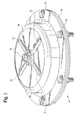
- FIG. 1 is a perspective view of a control valve pressure actuator
- FIG. 2 is a cross-sectional view taken along lines 2-2 of FIG.1 ;
- FIG. 3 is a perspective view of an alternate embodiment of a control valve pressure actuator.
- a control valve pressure actuator 10 is shown having an upper diaphragm casing 14 and a lower diaphragm casing 16.
- a vent or air port 18 is provided in the upper diaphragm casing 14, preferably at the center thereof, to facilitate application of pressure tubing (not shown).
- the control valve pressure actuator 10 is of the pressure-to-close type, meaning that a diaphragm 20 within the upper diaphragm casing 14 fails in an open position, adjacent the inside surface 22 of the upper diaphragm casing 14, when there is an absence of air pressure.
- the diaphragm 20 is mounted on a diaphragm plate 24.
- the diaphragm plate 24 is mounted on one or more springs 26, which serve to bias the diaphragm 20 toward the open position.
- a plurality of bolts 28 and nuts 30 are employed at periodic positions about the upper diaphragm casing 14 and lower diaphragm casing 16, with the diaphragm 20 secured therebetween.
- a top surface 32 of the upper diaphragm casing 14 is seen in FIG. 1 to include two raised projections thereon, which are preferably directed radially outwardly from the center of the upper diaphragm casing 14. Directly under these raised projections are channels 34, 36, which define air passages within the upper diaphragm casing 14.
- These air passage channels 34, 36 are preferably stamped into the upper diaphragm casing 14, and provide a region above the diaphragm 20 that allows for the circulation of air above the diaphragm 20 even when the diaphragm 20 is in its fully open position adjacent the inner surface 22 of the upper diaphragm casing 14.
- the air passage channels 34, 36 may be cast into the upper diaphragm casing 14.
- the upper diaphragm casing 14 is stamped, or alternately, cast, using a mold having a ridge on a top surface thereof for each air passage channel 34, 36 to be imparted to the upper diaphragm casing 14.
- the air passage channels 34, 36 each has an uppermost inner surface 38, 40, which is higher than the inner surface 22 of the upper diaphragm casing 14.
- the air passage channels 34, 36 preferably communicate with the air port 18.
- the air passage channels 34, 36 also advantageously enhance the stiffness of the upper diaphragm casing 14, enabling the control valve pressure actuator 10 to operate at even higher pressures than diaphragm casings lacking such air passage channels.
- a control valve pressure actuator 50 is shown having an upper diaphragm casing 54. Projecting radially outwardly from an air port 56, which is preferably provided at the center of the upper diaphragm casing 54, are four air passage channels 58, 60, 62, 64.
- the four air passage channels 58, 60, 62, 64 are like the air passage channels 34, 36 described in the previous embodiment, in that they each have an uppermost inner surface (not shown) which is higher than the inner surface (also not shown) of the upper diaphragm casing 54.
- the air passage channels 58, 60, 62, 64 allow the circulation of air above the diaphragm 68 (the outer edge of which is shown sandwiched between the upper diaphragm casing 54 and a lower diaphragm casing 70), even when the diaphragm 68 is in its fully open position, adjacent an inside surface of the top of the upper diaphragm casing 54.
- This circulation of air above the diaphragm 68 prevents the diaphragm 68 from sealing against the inside surface of the upper diaphragm casing 54 when the diaphragm is in the fully open position, and also enhances the stiffness of the upper diaphragm casing 54, enabling the control valve pressure actuator 50 to operate at higher pressures than comparable pressure actuators lacking such air passage channels.
- the first embodiment of the upper diaphragm casing 14 shown in FIGS. 1 and 2 has two air passage channels 34, 36
- the second embodiment of the upper diaphragm casing 54 shown in FIG. 3 has four air passage channels 58, 60, 62, 64
- there could be yet additional air passage channels provided in the upper diaphragm casing Preferably, the number of air passage channels is in a range from one to six, but the number is only limited by the ability to stamp or cast the air passage channels.
- an upper diaphragm casing may be provided with six radially extending air passage channels, arranged in an asterisk ("*") pattern about the centrally located air port.
- An aspect of the present invention includes air passage channels that may be provided by forming ridges on the diaphragm plate, instead of or in addition to (so long as not aligned with) the air passage channels provided in the upper diaphragm casing.
- the topography of the diaphragm plate, due to the ridges thereon, results in an uneven surface on which the diaphragm sits.
- Air passage channels are thereby formed between the top of the diaphragm and the inside surface of the top of the upper diaphragm casing, resulting in an increased area available beneath the top of the upper diaphragm casing for pressurization of the diaphragm, in a manner similar to the air passage channels located in the upper diaphragm casing, as described in the previous embodiments.
Landscapes
- Engineering & Computer Science (AREA)
- Physics & Mathematics (AREA)
- Fluid Mechanics (AREA)
- Mechanical Engineering (AREA)
- General Engineering & Computer Science (AREA)
- Actuator (AREA)
- Fluid-Driven Valves (AREA)
- Control Of Fluid Pressure (AREA)
- Fluid-Pressure Circuits (AREA)
Claims (5)
- Verbessertes Regelventildruckstellglied (10, 50) mit einem oberen Membrangehäuse (14, 54) mit einer zentral darin angeordneten Luftöffnung (18, 56), einem unteren Membrangehäuse (16, 70), einer Membran (20, 68), die zwischen dem oberen (14, 54) und dem unteren Membrangehäuse (16, 70) angeordnet ist, wobei die Membran (20, 68) an einem Membranteller (24) befestigt und durch eine oder mehrere Feder/n (26) zu einer vollständig offenen Stellung angrenzend an eine Innenfläche (22) an einem oberen Ende des oberen Membrangehäuses (14, 54) vorgespannt ist, wobei die Luftöffnung (18, 56) eine Wirkfläche der Membran (20, 68) bildet, so dass während der Betätigung des Regelventildruckstellglieds (10, 50) ein durch die Luftöffnung (18, 56) übertragener Luftdruck eine Betätigungskraft entgegen einer durch die Federn (26) erzeugten Kraft an der Wirkfläche erzeugt, wobei die Verbesserung umfasst:zwei oder mehr Luftdurchgangskanäle (34, 36, 58, 60, 62, 64) im oberen Membrangehäuse (14, 54), wobei die Luftdurchgangskanäle (34, 36, 58, 60, 62, 64) radial von der zentral angeordneten Luftöffnung (18, 56) nach außen ragen und symmetrisch um diese herum angeordnet sind, um die Wirkfläche der Membran (20, 68) wesentlich zu vergrößern, wodurch eine zusätzliche Betätigungskraft auf die Membran (20, 68) erzeugt wird, wenn die Membran (20, 68) aus der vollständig offenen Stellung verlagert wird, und wobei darüber hinaus die symmetrisch angeordneten Luftdurchgangskanäle (34, 36, 58, 60, 62, 64) für eine zusätzliche Versteifung des oberen Membrangehäuses (14, 54) sorgen, um eine Betätigung des Regelventildruckstellglieds (10, 50) bei höheren Drücken als herkömmliche Membrangehäuse zu ermöglichen,dadurch gekennzeichnet, dassder Membranteller (24) mit Stegen versehen ist, wobei die Stege dazu angepasst sind, eine unebene Oberfläche zu schaffen, auf der die Membran (20, 68) aufsitzen kann, wodurch zusätzliche Luftdurchgangskanäle bereitgestellt werden, wobei die zusätzlichen Luftdurchgangskanäle nicht mit den zwei oder mehr Luftdurchgangskanälen (34, 36, 58, 60, 62, 64) im oberen Membrangehäuse (14, 54) ausgerichtet sind.
- Verbessertes Regelventildruckstellglied (10, 50) nach Anspruch 1, wobei die Verbesserung darüber hinaus umfasst, dass die Anzahl von zwei oder mehr Luftdurchgangskanälen (34, 36, 58, 60, 62, 64) in einem Bereich von 2 bis 6 liegt.
- Verbessertes Regelventildruckstellglied (10, 50) nach den Ansprüchen 1 oder 2, wobei die Verbesserung darüber hinaus umfasst, dass jeder der zwei oder mehr Luftdurchgangskanäle (34, 36, 58, 60, 62, 64) ausgehend von einer allgemein flachen Oberfläche an der Oberseite des oberen Membrangehäuses (14, 54) nach oben ragt.
- Verfahren zum Verhindern, dass eine Membran (20, 68) eines Druckschließregelventildruckstellglieds (10, 50) in einer offenen Stellung dichtmacht, Folgendes umfassend:(a) Ausbilden einer Press-/Gießform für ein oberes Membrangehäuse (14, 54) mit zwei oder mehr Stegen an einer Oberseite von diesem;(b) Verwenden der ausgebildeten Press-/Gießform, um ein oberes Membrangehäuse (14, 54) für ein Regelventildruckstellglied (10, 50) zu pressen oder zu gießen, wobei die zwei oder mehr Stege entsprechend zwei oder mehr Luftdurchgangskanäle (34, 36, 58, 60, 62, 64) im oberen Membrangehäuse (14, 54) vermitteln, wobei die zwei oder mehr Luftdurchgangskanäle (34, 36, 58, 60, 62, 64) radial von einer im oberen Membrangehäuse (14, 54) befindlichen, zentral angeordneten Luftöffnung (18, 56) nach außen ragen und symmetrisch um diese herum angeordnet sind; und(c) Einbauen eines Regelventildruckstellglieds (10, 50) unter Verwendung des gepressten oberen Membrangehäuses (14, 54) so, dass die symmetrisch angeordneten Luftdurchgangskanäle (34, 36, 58, 60, 62, 64) über einer Membran (20, 68) ausgerichtet sind, die zwischen dem oberen Membrangehäuse (14, 54) und einem unteren Membrangehäuse (16, 70) angeordnet ist, um eine Luftzirkulation über der Membran (20, 68) zu ermöglichen, wenn die Membran (20, 68) zunächst aus einer vollständig offenen Stellung angrenzend an eine Innenfläche (22) an einem oberen Ende des Membrangehäuses (14, 54) verlagert wird, und um darüber hinaus für eine zusätzliche Versteifung des oberen Membrangehäuses (14, 54) zu sorgen und eine Betätigung des Regelventildruckstellglieds (10, 50) bei höheren Drücken als herkömmliche Membrangehäuse zu ermöglichen,
gekennzeichnet durch:Bereitstellen eines Membrantellers (24) mit Stegen, wobei die Stege eine unebene Oberfläche schaffen, auf der die Membran (20, 68) aufsitzen kann, wodurch zusätzliche Luftdurchgangskanäle bereitgestellt werden, wobei die zusätzlichen Luftdurchgangskanäle nicht mit den Luftdurchgangskanälen (34, 36, 58, 60, 62, 64) im oberen Membrangehäuse (14, 54) ausgerichtet sind. - Verfahren nach Anspruch 4, wobei beim Ausbilden der Press-/Gießform die Press-/Gießform mit einer Anzahl von Stegen in einem Bereich von 2 bis 6 versehen wird.
Applications Claiming Priority (3)
| Application Number | Priority Date | Filing Date | Title |
|---|---|---|---|
| US10/359,798 US6827001B2 (en) | 2003-02-06 | 2003-02-06 | Pressure actuator diaphragm casing with air passages |
| US359798 | 2003-02-06 | ||
| PCT/US2004/001486 WO2004072488A1 (en) | 2003-02-06 | 2004-01-21 | Pressure actuator diaphragm casing with air passages |
Publications (2)
| Publication Number | Publication Date |
|---|---|
| EP1599676A1 EP1599676A1 (de) | 2005-11-30 |
| EP1599676B1 true EP1599676B1 (de) | 2013-09-04 |
Family
ID=32823851
Family Applications (1)
| Application Number | Title | Priority Date | Filing Date |
|---|---|---|---|
| EP04704002.7A Expired - Lifetime EP1599676B1 (de) | 2003-02-06 | 2004-01-21 | Membrandruckerzeugerdeckel mit luftkanäle |
Country Status (7)
| Country | Link |
|---|---|
| US (1) | US6827001B2 (de) |
| EP (1) | EP1599676B1 (de) |
| JP (1) | JP4425907B2 (de) |
| CN (1) | CN100365291C (de) |
| BR (1) | BRPI0406909B1 (de) |
| CA (1) | CA2507231C (de) |
| WO (1) | WO2004072488A1 (de) |
Families Citing this family (10)
| Publication number | Priority date | Publication date | Assignee | Title |
|---|---|---|---|---|
| US7363851B2 (en) * | 2006-01-20 | 2008-04-29 | Fisher Controls International, Llc | Spacers for use with actuator casings |
| US7832327B2 (en) * | 2007-12-07 | 2010-11-16 | Fisher Controls International Llc | Ring sealed diaphragm |
| CN103765017B (zh) * | 2011-07-15 | 2017-04-05 | 机械解析有限公司 | 致动器 |
| US9568117B2 (en) | 2012-11-16 | 2017-02-14 | Ge Oil & Gas Pressure Control Lp | Combination diaphragm piston actuator |
| US8998166B2 (en) * | 2012-11-16 | 2015-04-07 | Ge Oil & Gas Pressure Control Lp | Combination diaphragm piston actuator |
| US10480675B2 (en) | 2012-12-31 | 2019-11-19 | Ge Oil & Gas Pressure Control Lp | No-bolt security latching system |
| US10132422B2 (en) | 2012-12-31 | 2018-11-20 | Ge Oil & Gas Pressure Control Lp | Compound express actuator connection |
| CA2896730C (en) * | 2012-12-31 | 2020-10-27 | Ge Oil & Gas Pressure Control Lp | Non-rising stem actuator |
| US9759240B2 (en) | 2012-12-31 | 2017-09-12 | Ge Oil & Gas Pressure Control Lp | No-bolt security latching system |
| CN106523772A (zh) * | 2016-12-06 | 2017-03-22 | 常熟市虞菱机械有限责任公司 | 一种大输出力阀门气动驱动装置 |
Family Cites Families (10)
| Publication number | Priority date | Publication date | Assignee | Title |
|---|---|---|---|---|
| US2574574A (en) * | 1945-04-25 | 1951-11-13 | Kieley And Mueller Inc | Fluid motor construction for valves or the like |
| US2608211A (en) * | 1949-06-08 | 1952-08-26 | Powers Regulator Co | Valve motor |
| US3241805A (en) * | 1962-10-23 | 1966-03-22 | Powers Regulator Co | Valve |
| DE1259162B (de) | 1965-07-12 | 1968-01-18 | Sabo Maschinenfabrik Heinrich | Hochdruck-Steuerventil |
| DE2740899B2 (de) | 1977-09-10 | 1980-04-17 | Graubremse Gmbh, 6900 Heidelberg | Membranzylinder für mit einem hydraulischen oder pneumatischen Druckmittel betriebene Betätigungseinrichtungen, insbesondere für Druckluftbremsanlagen in Kraftfahrzeugen |
| GB2106184A (en) | 1981-09-11 | 1983-04-07 | Dewandre Co Ltd C | Brake chamber |
| US4741252A (en) * | 1986-09-24 | 1988-05-03 | Allied-Signal Inc. | Diaphragm of the rolling type having a membrane portion and a reinforcing portion |
| DE4205756C2 (de) * | 1991-03-22 | 1997-12-18 | Jidosha Denki Kogyo Kk | Membranbetätigtes Stellglied |
| US6164187A (en) * | 1997-08-15 | 2000-12-26 | Holland Neway International, Inc. | Diaphragm retainer for spring brake actuator |
| US6349629B1 (en) * | 2000-08-25 | 2002-02-26 | Indian Head Industries, Inc. | Brake actuator |
-
2003
- 2003-02-06 US US10/359,798 patent/US6827001B2/en not_active Expired - Lifetime
-
2004
- 2004-01-21 BR BRPI0406909A patent/BRPI0406909B1/pt not_active IP Right Cessation
- 2004-01-21 WO PCT/US2004/001486 patent/WO2004072488A1/en not_active Ceased
- 2004-01-21 CA CA2507231A patent/CA2507231C/en not_active Expired - Lifetime
- 2004-01-21 EP EP04704002.7A patent/EP1599676B1/de not_active Expired - Lifetime
- 2004-01-21 JP JP2006502901A patent/JP4425907B2/ja not_active Expired - Fee Related
- 2004-01-21 CN CNB2004800034820A patent/CN100365291C/zh not_active Expired - Lifetime
Also Published As
| Publication number | Publication date |
|---|---|
| BRPI0406909B1 (pt) | 2017-03-21 |
| WO2004072488A1 (en) | 2004-08-26 |
| US6827001B2 (en) | 2004-12-07 |
| BRPI0406909A (pt) | 2005-12-13 |
| US20040154467A1 (en) | 2004-08-12 |
| CN100365291C (zh) | 2008-01-30 |
| EP1599676A1 (de) | 2005-11-30 |
| CA2507231C (en) | 2011-04-19 |
| JP4425907B2 (ja) | 2010-03-03 |
| CN1748087A (zh) | 2006-03-15 |
| JP2006517279A (ja) | 2006-07-20 |
| CA2507231A1 (en) | 2004-08-26 |
Similar Documents
| Publication | Publication Date | Title |
|---|---|---|
| EP1599676B1 (de) | Membrandruckerzeugerdeckel mit luftkanäle | |
| JP4128226B2 (ja) | 組込み逆止弁を備えた電磁弁 | |
| JP4971030B2 (ja) | 流体制御弁 | |
| JP2017171297A (ja) | 流量無反応二方向制御弁を持つ空気圧ブレーキアクチュエータ | |
| US20010032946A1 (en) | Diaphragm-type solenoid valve | |
| JP2559176Y2 (ja) | マスタシリンダ用リザーバのキャップ | |
| US20040182450A1 (en) | Fluid control valve | |
| JP4879285B2 (ja) | 反発性ダイヤフラムを備える弁 | |
| CA1235627A (en) | Switch and valve assembly | |
| KR101809810B1 (ko) | 다이어프램 밸브 | |
| JP2569124Y2 (ja) | アンチロックブレーキ装置の電磁弁 | |
| JP4141077B2 (ja) | リリーフ弁 | |
| US5887618A (en) | Fluid flow control valve device | |
| JP3787383B2 (ja) | クイックリリースバルブ | |
| JPH11201212A (ja) | 液圧緩衝器の減衰バルブ | |
| JP2006513905A (ja) | 圧力コントローラ | |
| JP2019530834A (ja) | ホイールブレーキのブレーキ圧を制御するための電磁弁、およびその弁体を製造するための金型 | |
| GB2066518A (en) | Pneumatic servo valve | |
| JPH11139285A (ja) | 車両用ブレーキ装置における液圧ユニットのリザーバ | |
| JPH0343896Y2 (de) | ||
| JP2622232B2 (ja) | 自動車ブレーキ補助制動装置 | |
| JP7769531B2 (ja) | バルブおよび緩衝器 | |
| JP2013126872A (ja) | 車両用ブレーキ液圧制御装置 | |
| KR102544752B1 (ko) | 체크밸브 | |
| JP2008115963A (ja) | 機器収納室のシール装置およびそれを使用したブレーキ液圧制御装置 |
Legal Events
| Date | Code | Title | Description |
|---|---|---|---|
| PUAI | Public reference made under article 153(3) epc to a published international application that has entered the european phase |
Free format text: ORIGINAL CODE: 0009012 |
|
| 17P | Request for examination filed |
Effective date: 20050906 |
|
| AK | Designated contracting states |
Kind code of ref document: A1 Designated state(s): AT BE BG CH CY CZ DE DK EE ES FI FR GB GR HU IE IT LI LU MC NL PT RO SE SI SK TR |
|
| AX | Request for extension of the european patent |
Extension state: AL LT LV MK |
|
| DAX | Request for extension of the european patent (deleted) | ||
| RBV | Designated contracting states (corrected) |
Designated state(s): DE FR GB |
|
| 17Q | First examination report despatched |
Effective date: 20070124 |
|
| GRAP | Despatch of communication of intention to grant a patent |
Free format text: ORIGINAL CODE: EPIDOSNIGR1 |
|
| INTG | Intention to grant announced |
Effective date: 20130405 |
|
| GRAS | Grant fee paid |
Free format text: ORIGINAL CODE: EPIDOSNIGR3 |
|
| GRAA | (expected) grant |
Free format text: ORIGINAL CODE: 0009210 |
|
| AK | Designated contracting states |
Kind code of ref document: B1 Designated state(s): DE FR GB |
|
| REG | Reference to a national code |
Ref country code: GB Ref legal event code: FG4D |
|
| REG | Reference to a national code |
Ref country code: DE Ref legal event code: R096 Ref document number: 602004043226 Country of ref document: DE Effective date: 20131031 |
|
| REG | Reference to a national code |
Ref country code: DE Ref legal event code: R097 Ref document number: 602004043226 Country of ref document: DE |
|
| PLBE | No opposition filed within time limit |
Free format text: ORIGINAL CODE: 0009261 |
|
| STAA | Information on the status of an ep patent application or granted ep patent |
Free format text: STATUS: NO OPPOSITION FILED WITHIN TIME LIMIT |
|
| 26N | No opposition filed |
Effective date: 20140605 |
|
| REG | Reference to a national code |
Ref country code: DE Ref legal event code: R097 Ref document number: 602004043226 Country of ref document: DE Effective date: 20140605 |
|
| REG | Reference to a national code |
Ref country code: FR Ref legal event code: PLFP Year of fee payment: 13 |
|
| REG | Reference to a national code |
Ref country code: FR Ref legal event code: PLFP Year of fee payment: 14 |
|
| REG | Reference to a national code |
Ref country code: FR Ref legal event code: PLFP Year of fee payment: 15 |
|
| PGFP | Annual fee paid to national office [announced via postgrant information from national office to epo] |
Ref country code: GB Payment date: 20221221 Year of fee payment: 20 Ref country code: FR Payment date: 20221220 Year of fee payment: 20 |
|
| PGFP | Annual fee paid to national office [announced via postgrant information from national office to epo] |
Ref country code: DE Payment date: 20221220 Year of fee payment: 20 |
|
| P01 | Opt-out of the competence of the unified patent court (upc) registered |
Effective date: 20230526 |
|
| REG | Reference to a national code |
Ref country code: DE Ref legal event code: R071 Ref document number: 602004043226 Country of ref document: DE |
|
| REG | Reference to a national code |
Ref country code: GB Ref legal event code: PE20 Expiry date: 20240120 |
|
| PG25 | Lapsed in a contracting state [announced via postgrant information from national office to epo] |
Ref country code: GB Free format text: LAPSE BECAUSE OF EXPIRATION OF PROTECTION Effective date: 20240120 |