EP1599670B1 - Blind hole and seat hole injection nozzle for an internal combustion engine, comprising a transition cone between the blind hole and the nozzle needle seat - Google Patents
Blind hole and seat hole injection nozzle for an internal combustion engine, comprising a transition cone between the blind hole and the nozzle needle seat Download PDFInfo
- Publication number
- EP1599670B1 EP1599670B1 EP03816024A EP03816024A EP1599670B1 EP 1599670 B1 EP1599670 B1 EP 1599670B1 EP 03816024 A EP03816024 A EP 03816024A EP 03816024 A EP03816024 A EP 03816024A EP 1599670 B1 EP1599670 B1 EP 1599670B1
- Authority
- EP
- European Patent Office
- Prior art keywords
- nozzle needle
- nozzle
- blind hole
- needle seat
- injection
- Prior art date
- Legal status (The legal status is an assumption and is not a legal conclusion. Google has not performed a legal analysis and makes no representation as to the accuracy of the status listed.)
- Expired - Lifetime
Links
- 238000002347 injection Methods 0.000 title claims description 84
- 239000007924 injection Substances 0.000 title claims description 84
- 230000007704 transition Effects 0.000 title claims description 24
- 238000002485 combustion reaction Methods 0.000 title claims description 21
- 238000005520 cutting process Methods 0.000 claims description 4
- 239000007921 spray Substances 0.000 claims description 4
- 239000000446 fuel Substances 0.000 description 21
- 239000006185 dispersion Substances 0.000 description 7
- 230000000694 effects Effects 0.000 description 5
- 238000013461 design Methods 0.000 description 4
- 238000004519 manufacturing process Methods 0.000 description 4
- 238000004904 shortening Methods 0.000 description 4
- 230000003746 surface roughness Effects 0.000 description 3
- 238000010586 diagram Methods 0.000 description 2
- 238000003754 machining Methods 0.000 description 2
- 238000000034 method Methods 0.000 description 2
- 238000007789 sealing Methods 0.000 description 2
- 238000012360 testing method Methods 0.000 description 2
- 230000007423 decrease Effects 0.000 description 1
- 238000004049 embossing Methods 0.000 description 1
- 239000002828 fuel tank Substances 0.000 description 1
- 239000000463 material Substances 0.000 description 1
- 238000005259 measurement Methods 0.000 description 1
- 230000002265 prevention Effects 0.000 description 1
- 238000012545 processing Methods 0.000 description 1
Images

Classifications
-
- F—MECHANICAL ENGINEERING; LIGHTING; HEATING; WEAPONS; BLASTING
- F02—COMBUSTION ENGINES; HOT-GAS OR COMBUSTION-PRODUCT ENGINE PLANTS
- F02M—SUPPLYING COMBUSTION ENGINES IN GENERAL WITH COMBUSTIBLE MIXTURES OR CONSTITUENTS THEREOF
- F02M61/00—Fuel-injectors not provided for in groups F02M39/00 - F02M57/00 or F02M67/00
- F02M61/16—Details not provided for in, or of interest apart from, the apparatus of groups F02M61/02 - F02M61/14
- F02M61/168—Assembling; Disassembling; Manufacturing; Adjusting
-
- F—MECHANICAL ENGINEERING; LIGHTING; HEATING; WEAPONS; BLASTING
- F02—COMBUSTION ENGINES; HOT-GAS OR COMBUSTION-PRODUCT ENGINE PLANTS
- F02M—SUPPLYING COMBUSTION ENGINES IN GENERAL WITH COMBUSTIBLE MIXTURES OR CONSTITUENTS THEREOF
- F02M61/00—Fuel-injectors not provided for in groups F02M39/00 - F02M57/00 or F02M67/00
- F02M61/16—Details not provided for in, or of interest apart from, the apparatus of groups F02M61/02 - F02M61/14
- F02M61/18—Injection nozzles, e.g. having valve seats; Details of valve member seated ends, not otherwise provided for
Definitions
- the invention relates to an injection nozzle for internal combustion engines having a, at least one injection hole having blind hole or a seat hole injection nozzle and with a subsequent to the blind hole nozzle needle seat.
- Blind injection nozzles of the generic type have, especially in sectionhub Scheme the nozzle needle, a large dispersion of Strömungswiderstands.und thus the injected fuel quantity.
- the emission and consumption behavior of many of the equipped with these blind injection nozzles internal combustion engine is not optimal.
- an injection nozzle is known in which the valve seat enclosing surfaces in front of the valve seat and behind the valve seat have an angle differences of about 10 degrees.
- the large angular difference leads to considerable deformations occurring during operation of the injection nozzle in the region of the contact zone between the nozzle needle and the nozzle needle seat. Due to these deformations, the operating behavior of the injection nozzle changes relatively strongly with increasing operating time.
- a distance between the cutting edge and the bottom of the blind hole is smaller than a distance between a contact zone of nozzle needle seat and a nozzle needle on the one hand and the bottom of the blind hole on the other hand, and is one with the Düsennadelsitz cooperating end of a nozzle needle formed frusto-conical.
- the proportion of the flow resistance of this frusto-conical annular gap decreases in the total flow resistance of the injection nozzle during the injection process in the partial load range of the internal combustion engine.
- variations in the flow resistance of the frusto-conical gap have less effect on the injection behavior of the injection nozzle. This reduces the dispersion of the operating behavior of the injection nozzles in series production.
- the injection nozzles of a large series behave almost identically in the partial stroke range, so that the control of these injectors by means of a control unit programmed with predetermined parameters leads to precisely predictable and equal injection quantities.
- the shortening of the annular gap between the nozzle needle seat and the nozzle needle also reduces the influence of the surface roughness of the nozzle needle seat or of the nozzle needle on the flow resistance in the partial lift region of the nozzle needle for the same reasons.
- the requirements for the surfaces to be machined, if desired, can be reduced and thus costs in the production of the injection nozzle according to the invention can be saved.
- the shortening of the annular gap leads with the two limiting angles on the needle and by the course according to the invention of the nozzle body angle to a wear limit when working the needle into the body.
- the operating behavior of a blind-hole injection nozzle can be predicted with much greater accuracy and the control of the injection process can be optimized accordingly.
- the transition can be designed not only as a transition cone, but also curvy.
- the cone angle of the transition cone corresponds approximately to the bisecting line between the blind hole and the nozzle needle seat.
- the inventive design of the transition between the blind hole and nozzle needle seat are used both in injectors with a conical and cylindrical blind hole.
- the nozzle needle seat frustoconical in particular with a conical seat of about 60 °, is executed, since then a good sealing effect and a good centering of the nozzle needle in the nozzle needle seat results.
- a cooperating with the nozzle needle end of a nozzle needle is frusto-conical, in a particularly advantageous embodiment of the invention, the cone angle up to 1 °, preferably 15 angular minutes - 30 minutes, greater than the cone angle of the nozzle needle seat, so that the sealing surface reduced and placed in the region of the largest diameter of the nozzle needle.
- the end of the nozzle needle cooperating with the nozzle needle seat may be designed to be double-frusto-conical.
- the nozzle needle seat is where the two truncated cones connect to each other.
- the one or more blind holes of the injection nozzle according to the invention may be formed as a mini blind hole or micro blind hole or seat hole.
- FIG. 1 an injection nozzle 1 is shown with a conical blind hole 2 in section. It is in the left half of the FIG. 1 an injection nozzle according to the prior art, while shown on the right side of FIG. 1 a first embodiment of an injection nozzle 1 according to the invention is shown.
- the blind hole 2 can also be cylindrical or it can be executed as a mini or microslack hole 2.
- the injection holes can also be arranged in a nozzle needle seat 4. In the latter, the volume of the blind hole 2 is opposite to in FIG. 1 shown reduced type. As a result, less fuel evaporates into the combustion chamber when the internal combustion engine is switched off.
- the fuel passes from the blind hole 2 in the combustion chamber of the internal combustion engine, also not shown (not shown).
- a frusto-conical nozzle needle seat 4 connects.
- the nozzle needle seat 4 may have a cone angle of, for example, 60 °.
- a nozzle needle 5 At the nozzle needle seat 4 is a nozzle needle 5.
- the cone angle of the nozzle needle 5 is greater than the cone angle of the nozzle needle seat.
- the contact zone 6 between the nozzle needle 5 and nozzle needle seat 4 in the region of the largest diameter of the nozzle needle 5 and the surface pressure between the nozzle needle 5 and nozzle needle seat 4 is increased.
- the difference of the cone angle of the nozzle needle 5 and nozzle needle seat 4 is in FIG. 1 exaggerated. As a rule, this difference is less than 1 and ranges from, for example, 15 angular minutes to 30 minutes of arc.
- edge 7 On the left side of FIG. 1 a transition between blind hole 2 and nozzle needle seat 4 according to the prior art as edge 7 is shown. This edge 7 is formed during grinding of the nozzle needle seat 4. Depending on the type of processing, the edge 7 may be a sharp degree or a smooth edge. The flow resistance of the edge 7 is substantially influenced by the nature of the same.
- the transition between blind hole 2 and nozzle needle seat 4 is designed differently. Between nozzle needle seat 4 and blind hole 2, a transition cone 8 is formed. This transition cone 8 causes the in FIG. 1 Below the contact zone 6 lying part of the nozzle needle seat 4 is shortened. The length of the lying below the contact zone 6 of the nozzle needle seat 4 is in FIG. 1 (right side) labeled "x". At the nozzle needle seat 4 closes on the right side of FIG. 1 the already mentioned transition cone 8, which then merges into the blind hole 2.
- FIG. 1 In a blind hole nozzle according to the prior art, as they in FIG. 1 is shown on the left side, the length of the nozzle needle seat 4 below the contact zone 6 is significantly larger. she is in FIG. 1 denoted by "y".
- a narrow frusto-conical annular gap between the nozzle needle seat 4 and the nozzle needle 5 results in the injection nozzle 1 according to the invention.
- the frustoconical annular gap (not shown) has the length "in the case of a nozzle needle according to the prior art.” y ", while in a blind hole injection nozzle 1 according to the invention only has a length" x ", where" x "is less than” y ".
- the measures x, y are variable with respect to the ratio; or and depending on the requirements depending on the test points of the injection system are designed.
- the flow resistance of this frusto-conical annular gap of an injection nozzle 1 according to the invention is much smaller than in a nozzle needle according to the prior art.
- the influence of the flow resistance of this frustoconical annular gap in the partial stroke on the injection behavior of an inventively designed injection nozzle 1 with a transition cone 8 is much smaller. Therefore, the dispersion of the operating behavior of injection nozzles 1, which are equipped according to the invention with a transition cone 8, with each other much smaller.
- the one or more injection holes 3 can also be arranged in the nozzle needle seat 4 or in the transition cone 8 (both not shown).
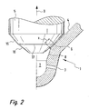
- FIG. 2 a second embodiment of an injection nozzle 1 according to the invention is shown.
- the cooperating with the nozzle needle seat 4 end of the nozzle needle 5 is designed as a double cone.
- a first cone 15 is followed by a second cone 16.
- the cone angle of the first cone 15 is smaller than the cone angle of the nozzle needle seat 4 and the cone angle of the second cone 16 is greater than the cone angle of the nozzle needle seat 4.
- this causes the Contact zone 6 between the nozzle needle 5 and nozzle needle seat 4 is where the first cone 15 merges into the second cone 16.
- This transitional area is in FIG. 2 has been provided with the reference numeral 17.
- the length x of the frusto-conical annular gap between the nozzle needle 5 and the nozzle needle seat 4 in this embodiment becomes smaller than the first embodiment (see right side of FIG. 1 ) again shortened.
- the influence of the flow resistance of the annular gap between the nozzle needle 5 and nozzle needle seat 4 drops in the partial stroke of the injection nozzle 1 again on the dispersion of the flow resistance, which the performance of an internal combustion engine, which is aligned with the injection nozzles 1 according to the second embodiment, again.
- the transition cone 8 can be easily and inexpensively manufactured by grinding, countersinking, embossing or another machining or cutting machining process become.
- the nozzle needle 5 will incorporate something in the nozzle needle seat 4 in the region of the contact zone 6 by plastically deforming the nozzle needle seat 4 and removing and / or displacing some material from the nozzle needle seat 4.
- the length "x" of the annular gap between the nozzle needle 5 and nozzle needle seat 4 shortens with increasing operating time of the injection nozzle 1 according to the invention.
- FIG. 3 the hydraulic diameter 10 of a blind hole injection nozzle 1 is applied qualitatively over the nozzle needle lift 9.
- the hydraulic diameter 10 is a size by means of which any flow-through cross-sections are made comparable in terms of their flow resistance.
- the reference value is the flow resistance of a pipe with a circular cross-section. A cross section with a large hydraulic diameter has a low flow resistance and vice versa.
- the nozzle needle stroke 9 was divided into two areas.
- a first range extends from zero to "a”
- the second range hereinafter referred to as partial lift range, extends from “a” to "b”.
- At “c” is the full nozzle needle stroke reached.
- a very narrow gap results through which the pressurized fuel can flow into the blind hole 2 in the case of a very small nozzle needle lift 9 in the region of the contact zone 6 .
- This very narrow gap determines the flow resistance of the injection nozzle 1 and the needle stability in the nozzle body; d. H. the prevention of fluttering of the needle; decisive and thus determines the hydraulic diameter 10. Since the flow resistance of this very narrow gap is large, the hydraulic diameter 10 of the injection nozzle 1 is very small in the case of a very small nozzle needle stroke 9.
- the injection hole 3 of the injection nozzle 1 is decisive for the hydraulic Diameter of the injection nozzle 1.
- the effects of different surface roughnesses in the region of the frustoconical annular gap between the nozzle needle seat 4 and the nozzle needle 5 on the hydraulic diameter in the partial stroke range were indicated by the characteristic curves 11, 12 and 13.
- the dashed line curve 12 represents an injection nozzle 1 in which the annular gap in comparison to the characteristic curve 11 has a larger hydraulic diameter and consequently has lower throttle losses.
- the dashed line curve 13 shows the effects of an annular gap, which relative to the characteristic 11 in FIG. 3 has a stronger throttle effect.
- the map of the internal combustion engine and the associated injection system is determined by means of one or more selected reference injectors 1 by measurements.
- the maps determined in this way are based on all identical injection systems.
- the characteristic curve 11 is a measured characteristic curve of a reference injection nozzle, and that this characteristic curve 11 is stored in the control unit of the injection system. It is further assumed that two injection nozzles 1 removed from the series production have the characteristic curves 12 and 13. If the injection nozzles 1 interact with the characteristic curves 12 and 13 with a control unit in which the characteristic 11 is stored, the actual injection quantity in the partial stroke range does not coincide with the optimum injection quantity measured according to the characteristic 11 in the test specimens, so that the power and / or the emission behavior of the internal combustion engine deteriorates becomes.
- the shortening of the characteristic curves 11, 12 and 13 is reduced by the inventive shortening of the length "x" of the frustoconical annular gap in the partial stroke by the transition cone 8.
- the correspondence between the characteristic curve 11 stored in the control unit and the characteristic curves 12 and 13 of two injection nozzles taken from the series production is markedly improved.
- the match can for example be improved by a factor of 2 to 3.
- the actual amount of fuel injected corresponds exactly to the injection quantity specified by the control unit and the fuel consumption and emission behavior of the internal combustion engine is optimal.
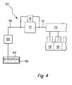
- the fuel injection system 102 includes a fuel tank 104 from which fuel 106 is conveyed by an electric or mechanical fuel pump 108. Via a low-pressure fuel line 110, the fuel 106 is conveyed to a high-pressure fuel pump 111. Of the high-pressure fuel pump 111, the fuel 106 passes through a high-pressure fuel line 112 to a common rail 114. On the common rail 114 a plurality of fuel injection nozzles 1 according to the invention are connected, which inject the fuel 106 directly into combustion chambers 118 of an internal combustion engine, not shown.
- the erfindunstrae injector can be used in a variety of injection system 102 and in various designs. Your benefits are particularly important High-pressure fuel injection systems with injection pressures> 1600 bar to day.
Landscapes
- Engineering & Computer Science (AREA)
- Chemical & Material Sciences (AREA)
- Combustion & Propulsion (AREA)
- Mechanical Engineering (AREA)
- General Engineering & Computer Science (AREA)
- Manufacturing & Machinery (AREA)
- Fuel-Injection Apparatus (AREA)
Description
Die Erfindung geht aus von einer Einspritzdüse für Brennkraftmaschinen mit einem, mindestens ein Spritzloch aufweisenden Sackloch beziehungsweise eine Sitzloch-Einspritzdüse und mit einem an das Sackloch anschließenden Düsennadelsitz.The invention relates to an injection nozzle for internal combustion engines having a, at least one injection hole having blind hole or a seat hole injection nozzle and with a subsequent to the blind hole nozzle needle seat.
Sackloch-Einspritzdüsen der gattungsgemäßen Art weisen vor allem im Teilhubbereich der Düsennadel eine große Streuung des Strömungswiderstands.und damit auch der eingespritzten Kraftstoffmenge auf. In Folge dessen ist das Emissions- und Verbrauchsverhalten vieler der mit diesen Sackloch-Einspritzdüsen ausgerüsteten Brennkraftmaschinen nicht optimal.Blind injection nozzles of the generic type have, especially in Teilhubbereich the nozzle needle, a large dispersion of Strömungswiderstands.und thus the injected fuel quantity. As a result, the emission and consumption behavior of many of the equipped with these blind injection nozzles internal combustion engine is not optimal.
Aus der
Aus der
Aus der
Bei einer erfindungsgemäße Einspritzdüse für eine Brennkraftmaschine nach dem Oberbegriff des Anspruchs 1 ist ein Abstand zwischen der Schnittkante und dem Grund des Sackloches kleiner ist als ein Abstand zwischen einer Kontaktzone von Düsennadelsitz und einer Düsennadel einerseits und dem Grund des Sackloches andererseits, und ist ein mit dem Düsennadelsitz zusammenwirkendes Ende einer Düsennadel kegelstumpfförmig ausgebildet. Durch die erfindungsgemäße Ausgestaltung wird der im Teilhub vorhandene kegelstumpfförmige Ringspalt zwischen Düsennadel und Düsennadelsitz stark verkürzt, so dass sich dessen Strömungswiderstand stark verringert. Dadurch sinkt der Anteil des Strömungswiderstands dieses kegelstumpfförmigen Ringspalts am Gesamtströmungswiderstand der Einspritzdüse während des Einspritzvorgangs im Teillastbereich der Brennkraftmaschine. Im Ergebnis wirken sich somit Streuungen des Strömungswiderstands des kegelstumpfförmigen Spalts weniger stark auf das Einspritzverhalten der Einspritzdüse aus. Dadurch werden die Streuungen des Betriebsverhaltens der Einspritzdüsen bei der Serienproduktion verringert. Die Einspritzdüsen einer Großserie verhalten sich nahezu identisch im Teilhubbereich, so dass die Ansteuerung dieser Einspritzdüsen durch ein mit vorgegebenen Parametern programmiertes Steuergerät zu exakt vorhersehbaren und gleich großen Einspritzmengen führt.In an injector according to the invention for an internal combustion engine according to the preamble of claim 1, a distance between the cutting edge and the bottom of the blind hole is smaller than a distance between a contact zone of nozzle needle seat and a nozzle needle on the one hand and the bottom of the blind hole on the other hand, and is one with the Düsennadelsitz cooperating end of a nozzle needle formed frusto-conical. As a result of the configuration according to the invention, the frustoconical annular gap existing between the nozzle needle and the nozzle needle seat in the partial stroke is greatly shortened so that its flow resistance is greatly reduced. As a result, the proportion of the flow resistance of this frusto-conical annular gap decreases in the total flow resistance of the injection nozzle during the injection process in the partial load range of the internal combustion engine. As a result, variations in the flow resistance of the frusto-conical gap have less effect on the injection behavior of the injection nozzle. This reduces the dispersion of the operating behavior of the injection nozzles in series production. The injection nozzles of a large series behave almost identically in the partial stroke range, so that the control of these injectors by means of a control unit programmed with predetermined parameters leads to precisely predictable and equal injection quantities.
Dies führt im Ergebnis zu einer Verbesserung des Verbrauchs- und Emissionsverhaltens der Brennkraftmaschine sowie einer Verbesserung des Rundlaufs der Brennkraftmaschine insbesondere im Teillastbereich.As a result, this leads to an improvement in the fuel consumption and emission behavior of the internal combustion engine as well as an improvement in the concentricity of the internal combustion engine, in particular in the partial load range.
Durch die Verkürzung des Ringspalts zwischen Düsennadelsitz und Düsennadel wird auch der Einfluss der Oberflächenrauigkeit des Düsennadelsitzes beziehungsweise der Düsennadel auf den Strömungswiderstand im Teilhubbereich der Düsennadel aus den gleichen Gründen verringert. Somit können die Anforderungen an die zu bearbeitenden Oberflächen, falls gewünscht, herabgesetzt werden und somit Kosten bei der Herstellung der erfindungsgemäßen Einspritzdüse eingespart werden.The shortening of the annular gap between the nozzle needle seat and the nozzle needle also reduces the influence of the surface roughness of the nozzle needle seat or of the nozzle needle on the flow resistance in the partial lift region of the nozzle needle for the same reasons. Thus, the requirements for the surfaces to be machined, if desired, can be reduced and thus costs in the production of the injection nozzle according to the invention can be saved.
Die Verkürzung des Ringspaltes führt mit den beiden begrenzenden Winkeln an der Nadel und durch den erfindungsgemäßen Verlauf des Düsenkörperwinkels zu einer Verschleißgrenze beim Einarbeiten der Nadel in den Körper.The shortening of the annular gap leads with the two limiting angles on the needle and by the course according to the invention of the nozzle body angle to a wear limit when working the needle into the body.
Schließlich kann durch Messen des Betriebsverhaltens einer erfindungsgemäßen Sacklocheinspritzdüse das Betriebsverhalten aller anderen bauartgleichen Sacklocheinspritzdüsen mit wesentlich größerer Genauigkeit vorhergesagt werden und die Steuerung des Einspritzvorgangs entsprechend optimiert werden. Der Übergang kann nicht nur als Übergangskegel, sondern auch kurvenförmig angelegt sein.Finally, by measuring the operating behavior of a blind-hole injection nozzle according to the invention, the operating behavior of all other identical-type blind hole injection nozzles can be predicted with much greater accuracy and the control of the injection process can be optimized accordingly. The transition can be designed not only as a transition cone, but also curvy.
Es hat sich als vorteilhaft erwiesen, wenn der Kegelwinkel des Übergangskegels in etwa der Winkelhalbierenden zwischen dem Sackloch und dem Düsennadelsitz entspricht. Die erfindungsgemäße Ausgestaltung des Übergangs zwischen Sackloch und Düsennadelsitz sowohl bei Einspritzdüsen mit konischem als auch mit zylindrischem Sackloch eingesetzt werden.It has proved to be advantageous if the cone angle of the transition cone corresponds approximately to the bisecting line between the blind hole and the nozzle needle seat. The inventive design of the transition between the blind hole and nozzle needle seat are used both in injectors with a conical and cylindrical blind hole.
Des Weiteren hat es sich als vorteilhaft erwiesen, wenn der Düsennadelsitz kegelstumpfförmig, insbesondere mit einem Kegelsitz von etwa 60 °, ausgeführt ist, da sich dann eine gute Dichtwirkung und eine gute Zentrierung der Düsennadel im Düsennadelsitz ergibt.Furthermore, it has proved to be advantageous if the nozzle needle seat frustoconical, in particular with a conical seat of about 60 °, is executed, since then a good sealing effect and a good centering of the nozzle needle in the nozzle needle seat results.
Es ist vorgesehen, dass ein mit dem Düsennadelsitz zusammenwirkendes Ende einer Düsennadel kegelstumpfförmig ausgebildet ist, wobei in besonders vorteilhafter Ausgestaltung der Erfindung der Kegelwinkel bis zu 1 °, vorzugsweise 15 Winkelminuten - 30 Winkelminuten, größer als der Kegelwinkel des Düsennadelsitzes ist, so dass die Dichtfläche verkleinert und in den Bereich des größten Durchmessers der Düsennadel verlegt wird.It is envisaged that a cooperating with the nozzle needle end of a nozzle needle is frusto-conical, in a particularly advantageous embodiment of the invention, the cone angle up to 1 °, preferably 15 angular minutes - 30 minutes, greater than the cone angle of the nozzle needle seat, so that the sealing surface reduced and placed in the region of the largest diameter of the nozzle needle.
Alternativ kann das mit dem Düsennadelsitz zusammenwirkende Ende der Düsennadel doppelt kegelstumpfförmig ausgebildet sein. In diesem Fall ist der Düsennadelsitz dort, wo die beiden Kegelstümpfe aneinander anschließen.Alternatively, the end of the nozzle needle cooperating with the nozzle needle seat may be designed to be double-frusto-conical. In this case, the nozzle needle seat is where the two truncated cones connect to each other.
Das oder die Sacklöcher der erfindungsgemäßen Einspritzdüse können als Mini-Sackloch oder Mikro-Sackloch oder Sitzloch ausgebildet sein.The one or more blind holes of the injection nozzle according to the invention may be formed as a mini blind hole or micro blind hole or seat hole.
Auch bei Sitzloch-Einspritzdüsen kann die erfindungsgemäße Ausgestaltung mit Erfolg eingesetzt werden.Even with seat hole injectors, the inventive design can be used successfully.
Weitere Vorteile und vorteilhafte Ausgestaltungen der Erfindung sind der nachfolgenden Zeichnung, deren Beschreibung und den Patentansprüchen entnehmbar.Further advantages and advantageous embodiments of the invention are the following drawings, the description and the claims removable.
Es zeigen:
- Figur 1
- ein erstes Ausführungsbeispiel einer erfindungsgemäßen Einspritzdüse im Schnitt,
Figur 2- ein zweites Ausführungsbeispiel einer erfindungsgemäßen Einspritzdüse,
Figur 3- eine Kennlinie des hydraulischen Durchmessers der Einspritzdüse über dem Hub der Düsennadel und
- Figur 4
- eine schematische Darstellung eines Kraftstoffeinspritzsystems für eine Brennkraftmaschine.
- FIG. 1
- a first embodiment of an injection nozzle according to the invention in section,
- FIG. 2
- A second embodiment of an injection nozzle according to the invention,
- FIG. 3
- a characteristic of the hydraulic diameter of the injector over the stroke of the nozzle needle and
- FIG. 4
- a schematic representation of a fuel injection system for an internal combustion engine.
In
Nachfolgend wird zunächst die linke Hälfte der
Das Sackloch 2 kann auch zylindrisch sein oder es kann um als Mini- oder Mikrosackloch 2 ausgeführt werden. Die Spritzlöcher können auch in einem Düsennadelsitz 4 angeordnet sein. Bei letztgenanntem ist das Volumen des Sacklochs 2 gegenüber der in
Über ein Spritzloch 3 gelangt der nicht dargestellte Kraftstoff aus dem Sackloch 2 in den ebenfalls nicht dargestellten Brennraum der Brennkraftmaschine (nicht dargestellt). An das konische Sackloch 2 schließt sich ein kegelstumpfförmiger Düsennadelsitz 4 an. Der Düsennadelsitz 4 kann einen Kegelwinkel von beispielsweise 60 ° haben.Via a
An dem Düsennadelsitz 4 liegt eine Düsennadel 5 auf. In
Auf der linken Seite von
Auf der rechten Seite von
Bei einer Sacklochdüse nach dem Stand der Technik, wie sie in
Wenn nun die Düsennadel in Richtung eines Düsennadelhubs 9 vom Düsennadelsitz abhebt, entsteht bei der erfindungsgemäßen Einspritzdüse 1 ein schmaler kegelstumpfförmiger Ringspalt zwischen Düsennadelsitz 4 und der Düsennadel 5. Der kegelstumpfförmige Ringspalt (nicht dargestellt) hat bei einer Düsennadel nach dem Stand der Technik die Länge "y", während er bei einer erfindungsgemäßen Sacklocheinspritzdüse 1 nur eine Länge "x" hat, wobei "x" kleiner als "y" ist. Die Maße x, y sind jedoch bezüglich des Verhältnisses variabel ; oder und je nach Anforderungen in Abhängigkeit der Prüfpunkte des Einspritzsystems ausgelegt werden.If the nozzle needle now lifts off from the nozzle needle seat in the direction of a
Wegen der gegenüber dem Stand der Technik stark verkürzten Länge des kegelstumpfförmigen Spalts zwischen Düsennadel 5 und Düsennadelsitz 4 im Teilhub ist naturgemäß auch der Strömungswiderstand dieses kegelstumpfförmigen Ringspalts einer erfindungsgemäßen Einspritzdüse 1 sehr viel kleiner als bei einer Düsennadel nach dem Stand der Technik. Infolgedessen ist der Einfluss des Strömungswiderstands dieses kegelstumpfförmigen Ringspalts im Teilhub auf das Einspritzverhalten einer erfindungsgemäß ausgestalteten Einspritzdüse 1 mit einem Übergangskegel 8 sehr viel kleiner. Deshalb ist die Streuung des Betriebsverhaltens von Einspritzdüsen 1, die erfindungsgemäß mit einem Übergangskegel 8 ausgestattet sind, untereinander sehr viel kleiner.Because of the greatly shortened compared to the prior art length of the frustoconical gap between the
Die Folgen der Streuung des Strömungswiderstands von Einspritzdüsen 1 werden nachfolgend anhand des in
Das oder die Spritzlöcher 3 können auch im Düsennadelsitz 4 oder im Übergangskegel 8 (beides nicht dargestellt) angeordnet sein.The one or
In
Der Übergangskegel 8 kann durch Schleifen, Senken, Prägen oder ein anderes spanendes oder spanloses Bearbeitungsverfahren einfach und kostengünstig hergestellt werden.The
Im Betrieb wird sich die Düsennadel 5 im Bereich der Kontaktzone 6 etwas in den Düsennadelsitz 4 einarbeiten, indem sie den Düsennadelsitz 4 plastisch verformt und etwas Material vom Düsennadelsitz 4 abträgt und/oder verdrängt. Infolgedessen verkürzt sich die Länge "x" des Ringspalts zwischen Düsennadel 5 und Düsennadelsitz 4 mit zunehmender Betriebsdauer der erfindungsgemäßen Einspritzdüse 1. Wenn die Länge "x" gleich null geworden ist, das heißt, wenn sich die Kontaktzone 6 an den Übergang zwischen Düsennadelsitz 4 und Übergangskegel 8 verlagert hat, ist die Verschleißgrenze der erfindungsgemäßen Einspritzdüse 1 erreicht.In operation, the
Nachfolgend werden anhand des in
In
In
Wenn eine geschlossene Einspritzdüse 1, bei der die Düsennadel 5 auf dem Düsennadelsitz 4 aufliegt, geöffnet wird, ergibt sich bei sehr kleinem Düsennadelhub 9 im Bereich der Kontaktzone 6 ein sehr schmaler Spalt, durch den der unter Druck stehende Kraftstoff in das Sackloch 2 strömen kann. Dieser sehr schmale Spalt bestimmt den Strömungswiderstand der Einspritzdüse 1 und die Nadelstabilität im Düsenkörper; d. h. die Verhinderung von Flattern der Nadel; maßgeblich und legt damit auch den hydraulischen Durchmesser 10 fest. Da der Strömungswiderstand dieses sehr schmalen Spalts groß ist, ist der hydraulische Durchmesser 10 der Einspritzdüse 1 bei sehr kleinem Düsennadelhub 9 sehr klein.If a closed injection nozzle 1, in which the
Im Teilhubbereich zwischen "a" und "b" wird der Strömungswiderstand der Einspritzdüse 1 maßgeblich von der Länge des kegelstumpfförmigen Ringspaltes zwischen Düsennadel 5 und Düsennadelsitz 4 bestimmt. Die Länge dieses Ringspaltes ist, in den
Im Bereich des vollen Düsennadelhubs "c" ist das Spritzloch 3 der Einspritzdüse 1 maßgeblich für den hydraulischen Durchmesser der Einspritzdüse 1.In the area of the full nozzle needle stroke "c", the
In
Bei in Serie gefertigten Brennkraftmaschinen wird das Kennfeld der Brennkraftmaschine und des zugehörigen Einspritzsystems anhand eines oder mehrerer ausgewählter Referenz-Einspritzdüsen 1 durch Messungen ermittelt. Die solcherart ermittelten Kennfelder werden allen bauartgleichen Einspritzsystemen zugrundegelegt.In series-produced internal combustion engines, the map of the internal combustion engine and the associated injection system is determined by means of one or more selected reference injectors 1 by measurements. The maps determined in this way are based on all identical injection systems.
Im Folgenden wird angenommen, dass die Kennlinie 11 eine gemessene Kennlinie einer Referenz-Einspritzdüse ist, und dass diese Kennlinie 11 in dem Steuergerät des Einspritzsystems abgespeichert ist. Weiter wird unterstellt, dass zwei der Serienfertigung entnommene Einspritzdüsen 1 die Kennlinien 12 und 13 haben. Wenn nun die Einspritzdüsen 1 mit den Kennlinien 12 und 13 mit einer Steuergerät zusammenwirken, in dem die Kennlinie 11 abgespeichert ist, dann stimmt die tatsächliche Einspritzmenge im Teilhubbereich nicht mit der bei den Testexemplaren gemessenen optimalen Einspritzmenge gemäß der Kennlinie 11 überein, so dass die Leistung und/oder das Emissionsverhalten der Brennkraftmaschine verschlechtert wird.In the following, it is assumed that the
Im Umkehrschluss kann man sagen, dass durch das erfindungsgemäße Verkürzen der Länge "x" des kegelstumpfförmigen Ringspalts im Teilhub durch den Übergangskegel 8 die Streuung der Kennlinien 11, 12 und 13 verringert wird. Damit wird die Übereinstimmung zwischen der im Steuergerät abgespeicherten Kennlinie 11 und der Kennlinien 12 und 13 von zwei der Serienfertigung entnommenen Einspritzdüsen deutlich verbessert. Die Übereinstimmung kann beispielsweise um den Faktor 2 bis 3 verbessert werden. In Folge dessen entspricht die tatsächlich eingespritzte Kraftstoffmenge genau der von dem Steuergerät vorgegebenen Einspritzmenge und das Verbrauchs- und Emissionsverhalten der Brennkraftmaschine ist optimal.Conversely, it can be said that the shortening of the
Anhand der
Die erfindungemäße Einspritzdüse kann in verschiedensten Einspritzanlage 102 und in verschiedenen Bauformen eingesetzt werden. Ihre Vorteile treten besonders bei Hochdruck-Kraftstoffeinspritzanlagen mit Einspritzdrücken > 1600 bar zu Tage.The erfindungemäße injector can be used in a variety of
Claims (11)
- Injection nozzle (1) for internal combustion engines having a blind hole (2) which has at least one spray hole (3) and having a nozzle needle seat (4) which adjoins the blind hole (2), with a transition cone (8) being provided between the blind hole (3) and the nozzle needle seat (4), with the nozzle needle seat (4) and the transition cone (8) forming a cutting edge, characterized in that a spacing between the cutting edge and the base of the blind hole (2) is smaller than a spacing between the contact zone (6) of the nozzle needle seat (4) and a nozzle needle (5) on the one hand and the base of the blind hole (2) on the other hand, and in that an end, which interacts with the nozzle needle seat (4), of a nozzle needle (5) is formed in the shape of a truncated cone.
- Injection nozzle (1) according to Claim 1, characterized in that a cone angle () of the transition cone (8) corresponds approximately to the angle bisector between the blind hole (2) and the nozzle needle seat (4).
- Injection nozzle (1) according to Claim 1 or 2, characterized in that the blind hole (2) is conical.
- Injection nozzle (1) according to Claim 1 or 2, characterized in that the blind hole (2) is cylindrical.
- Injection nozzle (1) according to one of the preceding claims, characterized in that the nozzle needle seat (4) is in the shape of a truncated cone.
- Injection nozzle (1) according to Claim 5, characterized in that the cone angle of the nozzle needle seat (4) is 60°.
- Injection nozzle (1) according to one of the preceding claims, characterized in that that end of the nozzle needle (5) which interacts with the nozzle needle seat (4) is formed in the shape of a double truncated cone.
- Injection nozzle (1) according to one of the preceding claims, characterized in that a cone angle of a nozzle needle (5) is up to one degree, preferably 15 to 30 angular minutes, greater than the cone angle of the nozzle needle seat (4).
- Injection nozzle (1) according to one of the preceding claims, characterized in that the blind hole (2) is a mini blind hole or a micro blind hole.
- Injection nozzle (1) according to one of the preceding claims, characterized in that the transition between the spray hole (3) and blind hole (2) is rounded.
- Injection nozzle (1) according to one of the preceding claims, characterized in that the at least one spray hole (3) is arranged in the nozzle needle seat (4) or in the transition cone (8).
Applications Claiming Priority (3)
| Application Number | Priority Date | Filing Date | Title |
|---|---|---|---|
| DE2003107873 DE10307873A1 (en) | 2003-02-25 | 2003-02-25 | Blind hole and seat hole injection nozzle for an internal combustion engine with a transition cone between the blind hole and nozzle needle seat |
| DE10307873 | 2003-02-25 | ||
| PCT/DE2003/002790 WO2004076850A1 (en) | 2003-02-25 | 2003-08-21 | Blind hole and seat hole injection nozzle for an internal combustion engine, comprising a transition cone between the blind hole and the nozzle needle seat |
Publications (2)
| Publication Number | Publication Date |
|---|---|
| EP1599670A1 EP1599670A1 (en) | 2005-11-30 |
| EP1599670B1 true EP1599670B1 (en) | 2008-03-19 |
Family
ID=32797715
Family Applications (1)
| Application Number | Title | Priority Date | Filing Date |
|---|---|---|---|
| EP03816024A Expired - Lifetime EP1599670B1 (en) | 2003-02-25 | 2003-08-21 | Blind hole and seat hole injection nozzle for an internal combustion engine, comprising a transition cone between the blind hole and the nozzle needle seat |
Country Status (3)
| Country | Link |
|---|---|
| EP (1) | EP1599670B1 (en) |
| DE (2) | DE10307873A1 (en) |
| WO (1) | WO2004076850A1 (en) |
Cited By (3)
| Publication number | Priority date | Publication date | Assignee | Title |
|---|---|---|---|---|
| CN105492757A (en) * | 2013-08-30 | 2016-04-13 | 罗伯特·博世有限公司 | Fuel injector |
| EP3073107A1 (en) | 2015-03-25 | 2016-09-28 | Robert Bosch Gmbh | Fuel injection valve for combustion engines and use of the fuel injection valve |
| DE102015205416A1 (en) | 2015-03-25 | 2016-09-29 | Robert Bosch Gmbh | Fuel injection valve for internal combustion engines |
Families Citing this family (4)
| Publication number | Priority date | Publication date | Assignee | Title |
|---|---|---|---|---|
| DE102004063166A1 (en) * | 2004-12-29 | 2006-07-13 | Robert Bosch Gmbh | Dosing device for liquids has at least part of boring in form of widening produced by stamping or pressing |
| JP2007224746A (en) * | 2006-02-21 | 2007-09-06 | Isuzu Motors Ltd | Injector nozzle |
| DE102010026687A1 (en) * | 2010-07-09 | 2012-01-12 | Continental Automotive Gmbh | Nozzle body for a fuel injector and method of manufacturing a nozzle body |
| US9903329B2 (en) | 2012-04-16 | 2018-02-27 | Cummins Intellectual Property, Inc. | Fuel injector |
Family Cites Families (7)
| Publication number | Priority date | Publication date | Assignee | Title |
|---|---|---|---|---|
| DE932209C (en) * | 1952-04-13 | 1955-08-25 | Bosch Gmbh Robert | Fuel injector |
| DE3014958A1 (en) * | 1980-04-18 | 1981-10-29 | Robert Bosch Gmbh, 7000 Stuttgart | Fuel injector IC engine - has needle valve shaped to avoid wear effects on seat dia. |
| EP0283154A1 (en) * | 1987-03-14 | 1988-09-21 | LUCAS INDUSTRIES public limited company | Fuel injection nozzle |
| JPH10281041A (en) * | 1997-04-01 | 1998-10-20 | Mitsubishi Heavy Ind Ltd | Fuel injection valve |
| DE19820513A1 (en) * | 1998-05-08 | 1999-11-11 | Mtu Friedrichshafen Gmbh | Fuel injection nozzle for internal combustion engine |
| JP2000320429A (en) * | 1999-05-13 | 2000-11-21 | Denso Corp | Fuel injection nozzle |
| DE19931761A1 (en) * | 1999-07-08 | 2001-01-18 | Bosch Gmbh Robert | Blind hole injection nozzle for internal combustion engines with a rounded transition between blind hole and nozzle needle seat |
-
2003
- 2003-02-25 DE DE2003107873 patent/DE10307873A1/en not_active Withdrawn
- 2003-08-21 DE DE50309436T patent/DE50309436D1/en not_active Expired - Lifetime
- 2003-08-21 WO PCT/DE2003/002790 patent/WO2004076850A1/en not_active Ceased
- 2003-08-21 EP EP03816024A patent/EP1599670B1/en not_active Expired - Lifetime
Cited By (6)
| Publication number | Priority date | Publication date | Assignee | Title |
|---|---|---|---|---|
| CN105492757A (en) * | 2013-08-30 | 2016-04-13 | 罗伯特·博世有限公司 | Fuel injector |
| CN105492757B (en) * | 2013-08-30 | 2018-10-23 | 罗伯特·博世有限公司 | Fuel injector |
| EP3073107A1 (en) | 2015-03-25 | 2016-09-28 | Robert Bosch Gmbh | Fuel injection valve for combustion engines and use of the fuel injection valve |
| DE102015205416A1 (en) | 2015-03-25 | 2016-09-29 | Robert Bosch Gmbh | Fuel injection valve for internal combustion engines |
| WO2016150591A1 (en) | 2015-03-25 | 2016-09-29 | Robert Bosch Gmbh | Fuel injection valve for internal combustion engines |
| DE102015205423A1 (en) | 2015-03-25 | 2016-09-29 | Robert Bosch Gmbh | Fuel injection valve for internal combustion engines and use of the fuel injection valve |
Also Published As
| Publication number | Publication date |
|---|---|
| EP1599670A1 (en) | 2005-11-30 |
| WO2004076850A1 (en) | 2004-09-10 |
| DE10307873A1 (en) | 2004-09-02 |
| DE50309436D1 (en) | 2008-04-30 |
Similar Documents
| Publication | Publication Date | Title |
|---|---|---|
| EP2250365B1 (en) | Fuel distributor assembly | |
| EP1129287B1 (en) | Injection nozzle for an internal combustion engine with annular groove in said nozzle needle | |
| DE3151020C2 (en) | ||
| EP2522854A1 (en) | Valve assembly for a high pressure fuel pump and high pressure fuel pump | |
| EP1599670B1 (en) | Blind hole and seat hole injection nozzle for an internal combustion engine, comprising a transition cone between the blind hole and the nozzle needle seat | |
| EP2297447B1 (en) | High-pressure pump | |
| EP1537324B1 (en) | Device for ventilation of a supply unit | |
| DE19843616A1 (en) | Fuel injector | |
| EP1312796B1 (en) | Fuel injection valve | |
| WO2002079636A1 (en) | Injection valve | |
| EP1296054A1 (en) | Injection valve for a combustion engine | |
| EP1157208B1 (en) | Injection nozzle with blind bore for internal combustion engine with rounded passage between the blind bore and the injector needle seat | |
| DE10346075B4 (en) | Method for producing a fuel injection valve and fuel injection valve produced by this method | |
| EP1518050B1 (en) | Injector for an injection system | |
| DE19843912B4 (en) | fuel Injector | |
| EP1527272B1 (en) | Fuel-injector comprising a connecting area that can withstand high pressure | |
| WO2017220240A1 (en) | High-pressure fuel pump having a housing, and method for processing channels of a housing of a high-pressure fuel pump | |
| EP1574701A1 (en) | Common rail injector | |
| EP1771655B1 (en) | Adjusting nut | |
| DE102004022428A1 (en) | Injection valve for internal combustion engines | |
| EP2914839A1 (en) | Nozzle module for a fuel injector, and fuel injector | |
| EP4077908B1 (en) | Injection nozzle for injecting fuel under high pressure | |
| DE10346242B4 (en) | Injector body for a common rail injector | |
| DE102025119409A1 (en) | FUEL INJECTION NOZZLE AND NOZZLE ARRANGEMENT CONFIGURED TO LIMIT CAVITATION DAMAGE | |
| EP1759115A1 (en) | High pressure pump for a fuel injection device of an internal combustion engine |
Legal Events
| Date | Code | Title | Description |
|---|---|---|---|
| PUAI | Public reference made under article 153(3) epc to a published international application that has entered the european phase |
Free format text: ORIGINAL CODE: 0009012 |
|
| 17P | Request for examination filed |
Effective date: 20050926 |
|
| AK | Designated contracting states |
Kind code of ref document: A1 Designated state(s): AT BE BG CH CY CZ DE DK EE ES FI FR GB GR HU IE IT LI LU MC NL PT RO SE SI SK TR |
|
| RBV | Designated contracting states (corrected) |
Designated state(s): DE FR |
|
| 17Q | First examination report despatched |
Effective date: 20051223 |
|
| GRAP | Despatch of communication of intention to grant a patent |
Free format text: ORIGINAL CODE: EPIDOSNIGR1 |
|
| GRAS | Grant fee paid |
Free format text: ORIGINAL CODE: EPIDOSNIGR3 |
|
| GRAA | (expected) grant |
Free format text: ORIGINAL CODE: 0009210 |
|
| AK | Designated contracting states |
Kind code of ref document: B1 Designated state(s): DE FR |
|
| REF | Corresponds to: |
Ref document number: 50309436 Country of ref document: DE Date of ref document: 20080430 Kind code of ref document: P |
|
| ET | Fr: translation filed | ||
| PLBE | No opposition filed within time limit |
Free format text: ORIGINAL CODE: 0009261 |
|
| STAA | Information on the status of an ep patent application or granted ep patent |
Free format text: STATUS: NO OPPOSITION FILED WITHIN TIME LIMIT |
|
| 26N | No opposition filed |
Effective date: 20081222 |
|
| REG | Reference to a national code |
Ref country code: FR Ref legal event code: PLFP Year of fee payment: 14 |
|
| REG | Reference to a national code |
Ref country code: FR Ref legal event code: PLFP Year of fee payment: 15 |
|
| REG | Reference to a national code |
Ref country code: FR Ref legal event code: PLFP Year of fee payment: 16 |
|
| PGFP | Annual fee paid to national office [announced via postgrant information from national office to epo] |
Ref country code: FR Payment date: 20220822 Year of fee payment: 20 |
|
| PGFP | Annual fee paid to national office [announced via postgrant information from national office to epo] |
Ref country code: DE Payment date: 20221025 Year of fee payment: 20 |
|
| REG | Reference to a national code |
Ref country code: DE Ref legal event code: R071 Ref document number: 50309436 Country of ref document: DE |