EP1599361B1 - Kraftfahrzeugeinheit mit einer basis und einer verschiebaren und aus der basis herausziehbaren konsole - Google Patents
Kraftfahrzeugeinheit mit einer basis und einer verschiebaren und aus der basis herausziehbaren konsole Download PDFInfo
- Publication number
- EP1599361B1 EP1599361B1 EP04717131A EP04717131A EP1599361B1 EP 1599361 B1 EP1599361 B1 EP 1599361B1 EP 04717131 A EP04717131 A EP 04717131A EP 04717131 A EP04717131 A EP 04717131A EP 1599361 B1 EP1599361 B1 EP 1599361B1
- Authority
- EP
- European Patent Office
- Prior art keywords
- console
- base
- assembly according
- motor vehicle
- sliding
- Prior art date
- Legal status (The legal status is an assumption and is not a legal conclusion. Google has not performed a legal analysis and makes no representation as to the accuracy of the status listed.)
- Expired - Lifetime
Links
- 238000000605 extraction Methods 0.000 abstract description 37
- 230000000903 blocking effect Effects 0.000 abstract description 5
- 210000000078 claw Anatomy 0.000 description 9
- 238000006073 displacement reaction Methods 0.000 description 8
- 238000005096 rolling process Methods 0.000 description 2
- XAGFODPZIPBFFR-UHFFFAOYSA-N aluminium Chemical compound [Al] XAGFODPZIPBFFR-UHFFFAOYSA-N 0.000 description 1
- 229910052782 aluminium Inorganic materials 0.000 description 1
- 238000002955 isolation Methods 0.000 description 1
Images


Classifications
-
- B—PERFORMING OPERATIONS; TRANSPORTING
- B60—VEHICLES IN GENERAL
- B60R—VEHICLES, VEHICLE FITTINGS, OR VEHICLE PARTS, NOT OTHERWISE PROVIDED FOR
- B60R7/00—Stowing or holding appliances inside vehicle primarily intended for personal property smaller than suit-cases, e.g. travelling articles, or maps
- B60R7/04—Stowing or holding appliances inside vehicle primarily intended for personal property smaller than suit-cases, e.g. travelling articles, or maps in driver or passenger space, e.g. using racks
-
- B—PERFORMING OPERATIONS; TRANSPORTING
- B60—VEHICLES IN GENERAL
- B60N—SEATS SPECIALLY ADAPTED FOR VEHICLES; VEHICLE PASSENGER ACCOMMODATION NOT OTHERWISE PROVIDED FOR
- B60N2/00—Seats specially adapted for vehicles; Arrangement or mounting of seats in vehicles
- B60N2/75—Arm-rests
- B60N2/763—Arm-rests adjustable
- B60N2/773—Longitudinal adjustment
-
- B—PERFORMING OPERATIONS; TRANSPORTING
- B60—VEHICLES IN GENERAL
- B60N—SEATS SPECIALLY ADAPTED FOR VEHICLES; VEHICLE PASSENGER ACCOMMODATION NOT OTHERWISE PROVIDED FOR
- B60N2/00—Seats specially adapted for vehicles; Arrangement or mounting of seats in vehicles
- B60N2/75—Arm-rests
- B60N2/79—Adaptations for additional use of the arm-rests
- B60N2/793—Adaptations for additional use of the arm-rests for use as storage compartments
Definitions
- the present invention relates to an assembly for a motor vehicle, of the type comprising a base, a console movable by sliding relative to the base along a direction of sliding, and means for connecting the console to the base, the means of linkage comprising at least one movable locking element between a locking position, in which the bracket is locked relative to the base along the sliding direction and the locking element holds the bracket relative to the base against an extraction , and a sliding position, in which the console can slide relative to the base along the direction of sliding, the connecting means further allowing the console to release the base to extract it from the motor vehicle.
- the invention applies in particular to a central console assembly provided between right and left seats of a motor vehicle.
- EP-1 245 446 describes a console whose connection means at the base to block or slide the console, as well as to extract the vehicle. These connecting means comprise two rods and a pad. To extract the console, it rotates the pad to allow it to pass through a clearance provided in the base.
- This document also describes an assembly for a motor vehicle, comprising a base, a console movable by sliding relative to the base along a sliding direction, and connecting means of the console to the base to allow adjustment of the position of the console along the sliding direction over a setting stroke, the connecting means comprising two rods movable between a locking position, in which the bracket is locked relative to the base along the sliding direction and a sliding position, in which the console can slide relative to the base along the direction of sliding, the connecting means also making it possible to release the console from the base to extract it from the motor vehicle, said base comprising a extraction region in which a clearance is provided, said extraction region being located outside the adjustment path, and said rods in the position of b locating that can pass through the clearance to extract the console of the motor vehicle.
- U.S. 4,213,593 and U.S. 4,114,947 disclose means for attaching seats to frames to allow or block a longitudinal sliding of the seats and further to extract the seats relative to the frame.
- FR-2 762 811 describes a set of the aforementioned type.
- the base includes a slideway secured to the floor of the vehicle.
- the connecting means comprise two hooks forming locking elements. In the locking position, the hooks are engaged in notches distributed along the edges of the slide. In sliding position, they are retracted and released notches.
- the connecting means also comprise articulated links for moving the hooks between their locking positions and their sliding positions.
- the rods are used to move the hooks to third positions in which the hooks are sufficiently retracted to allow passage through a central slot of the slide.
- the console can be extracted from the motor vehicle, which can modulate the interior and, for example, to free up space inside the cabin.
- connection means of the console to the base described in this document require to provide in the console a link mechanism particularly complex and expensive to move the locking elements.
- An object of the invention is to solve this problem by providing a set of the aforementioned type, whose console can slide and be blocked along the base and be released from the base to extract it from the motor vehicle, but which is more simple and of lower cost and where the risks of accidental extraction are reduced.
- the subject of the invention is an assembly of the aforementioned type, characterized in that the base comprises an extraction region in which a clearance is provided, and in that the blocking element in the blocking position can pass through the clearance to extract the console of the motor vehicle.
- the invention further relates to a motor vehicle, characterized in that it comprises an assembly as defined above.
- orientations used are the usual orientations of a motor vehicle.
- the terms "front”, “rear”, “right” and “left” refer to the position of a driver and the direction of travel of the motor vehicle.
- the figure 1 schematically illustrates the interior of a motor vehicle.
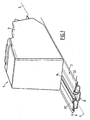
- a set 1 comprising a base 2 and a console 3 movable by sliding relative to the base 2 along a sliding direction L.
- the assembly 1 is disposed between the seats (not shown) front right and left of the motor vehicle and the sliding direction L is substantially coincident with the longitudinal direction of the motor vehicle.
- the base 2 is integral with the floor 6 of the motor vehicle and comprises a slide 8 which is made for example from an aluminum profile and which extends longitudinally.
- the console 3 has been shown in phantom on the figure 2 .
- the slideway 8 comprises two lateral wings 10 whose edges 12 arranged opposite delimit between them a central slot 14 extending over the entire length of the slide 8.
- the lateral wings 10 delimit between them a longitudinal passage 15 which opens upwards via the slot 14 in the cockpit.
- the central slot 14 has a substantially constant width L1 except in an extraction region 16 near its rear end 18.
- the slot 14 is enlarged by an extraction clearance 20 provided in the right edge 12.
- the slot 14 locally has a width L2 greater than L1.
- the right edge 12 (left on the figures 3 and 4 ) is wrapped with a folded sheet 24 whose section 26 disposed in the passage 15 under the right edge 12 has notches 28 regularly distributed over the length of the sheet 24.
- This sheet 24 extends from the extraction region 16 towards the front end 30 of the slide 8 to allow adjustment of the longitudinal position of the console 3 along a setting stroke CR ( fig.6 ), as will be described later.
- the base 2 further comprises two hubcaps 32 ( fig.3 ) which are arranged on either side of the slot 14 and cover the slideway 8.
- the base 2 comprises a stop 34 disposed in the passage 15 and movable under the action of a pull tab 36 between an extracted position illustrated by the figure 2 , in which the stop 34 projects laterally to the right under the slot 14, and a retracted position illustrated by the figure 7 in which the stop 34 has moved back to the left and no longer protrudes under the slot 14.
- a return member such as a spring can, for example bring the stop 34 to its extracted position.
- the console 3 conventionally comprises a body 38 providing a plurality of housings and receiving housing objects.
- the console 3 also comprises, for example, rollers 40 provided under the body 38 for rolling on the base 2.
- the console 3 comprises four rollers 40, two of which are intended to roll on the hubcap 32 right and two others are intended to roll on the hubcap 32 left.
- rollers 40 may be replaced by sliding pads.
- the bracket 3 is guided along the slide 8 during its sliding and held laterally with respect thereto.
- the console 3 further comprises means 44 for connecting the console 3 to the base 2.
- these connecting means 44 comprise a locking element in the form of a hook 46 provided under the body 38 of the bracket 3.
- the hook 46 extends downwards through the slot 14 and comprises, in the passage 15 , a cusp 48 ended by a claw 50 facing upwards.
- the hook 46 is disposed in front of the guide pin 42.
- the hook 46 has a width less than L2 but greater than L1, and a length less than that of the clearance 20.
- the vertical translation of the hook 46 between its two positions is provided by means 52 of displacement.
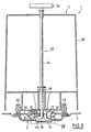
- these displacement means 52 comprise a rod 54 which extends through the body 38.
- the rod 54 is extended at its lower end by the hook 46.
- the upper end of the rod 54 is connected to a handle 56 disposed above the body 38.
- a spring 58 recalls the rod 54 upwards.
- the displacement means 52 may have different structures and comprise a link mechanism, with rods, cams, cables or levers, for example controlled by a handle carried by the upper face of the console 3.
- the hook 46 has only to move vertically between two positions, the mechanism of these last two documents can be greatly simplified.
- electric displacement means 52 can be used.
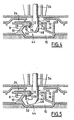
- the hook 46 When the hook 46 is in its raised position ( figure 4 ), it blocks longitudinally the console 3 relative to the base 2 because of the engagement of the claw 50 in a notch 28. If it is desired to move longitudinally the console 3, it controls the movement of the hook 46 to its position lowered ( fig.5 ).
- the console 3 can then slide relative to the base 2 between a position before end of adjustment stroke, illustrated by the figure 2 , and a retracted position illustrated by the figure 6 .
- the hook 46 When the console 3 occupies a desired position along the adjustment stroke CR, the hook 46 is returned to its raised locking position, and the claw 50 then engages in the notch 28 provided at this location. The console 3 is then locked longitudinally in the desired position relative to the base 2.
- connection means 44 thus make it possible to ensure longitudinal sliding and locking of the bracket 3.
- the hook 46 which is engaged under the right edge 12 opposes a vertical displacement of the bracket 3 relative to the base 2 and thus prevents any extraction of the console 3 when it is in the adjustment stroke CR. This is true both when the hook 46 is in the locking position in the sliding position.
- the abutment 34 is brought into its retracted position, which frees the access towards the rear end 18 of the slide 8.
- the console 3 can then slide along an extraction stroke CE ( fig.7 ) until the finger 42 comes into abutment against the rear end 18 of the slide 8.
- the console 3 is then in the position illustrated by the figure 7 which is an end-of-stroke extraction position CE.
- the claw 50 of the hook 46 is disposed under the clearance 20.
- the dimensions of the clearance 20 are large enough so that it does not oppose the passage of the hook 46, whether in the raised position of locking or in lowered sliding position.
- the connecting means 44 therefore also allow the release of the console 3 relative to the base 2 and its extraction from the motor vehicle.
- the means 52 of displacement provided in the console 3 can have a very simple and economical structure, since they must ensure the movement of the hook 46 between two positions without having to move to a third position allowing extraction of the console 3, as in the state of the art.
- the extraction of the console 3 can only be assured after controlled access to an extraction region 16 located outside the adjustment path CR of the console 3, the risk of accidental extraction of the console 3 are reduced.
- control of access to the extraction region 16 can be provided by means of a fixed stop 34 and a movable finger 42, for example by rotation or by translation.
- a fixed stop 34 and a movable finger 42 for example by rotation or by translation.
- Such a variant is illustrated by the Figures 8 and 9 .
- the finger 42 is rotated a quarter of a turn in order to pass the stop 34, as shown by the arrow 60 on the figure 8 .
- the movement of the finger 42 can be controlled by a very simple mechanism, distinct from the means 52 for moving the hook 46. It may advantageously be a simple lever arranged at the bottom of a housing of the console 3 and in direct contact with the finger 42.
- the displacement means present in the console 3 retain simple and economical structures.
- the slide 8 can be replaced by a rail whose two lateral edges 12 each have notches 28 for longitudinal locking of the console 3.
- the console 3 comprises two lateral hooks 46 which engage under the side edges of the rail. of the clearances allowing the passage of the hooks 46 are provided in the side edges of the rail to allow their extraction according to the principles described above.
- bracket 3 can be ensured by engagement of the claw 50 in a single slot 28, but also by the engagement of several projections of the claw 50 in several successive notches 28 .
Landscapes
- Engineering & Computer Science (AREA)
- Mechanical Engineering (AREA)
- Aviation & Aerospace Engineering (AREA)
- Transportation (AREA)
- Vehicle Step Arrangements And Article Storage (AREA)
- Fittings On The Vehicle Exterior For Carrying Loads, And Devices For Holding Or Mounting Articles (AREA)
- Motorcycle And Bicycle Frame (AREA)
- Instrument Panels (AREA)
Claims (10)
- Anordnung (1) für Kraftfahrzeug, eine Basis (2) umfassend, eine Konsole (3), die gleitend relativ zur Basis längs einer Gleitrichtung (L) bewegbar ist, und Mittel (44) zur Verbindung der Konsole mit der Basis, um die Einstellung der Stellung der Konsole (3) längs der Gleitrichtung über einen Einstellweg (CR) zu erlauben, wobei die Verbindungsmittel mindestens ein Verriegelungsteil (46) umfassen, das zwischen einer Verriegelungsstellung (Fig. 4), in der die Konsole mit der Basis in Gleitrichtung verriegelt ist und das Verriegelungsteil die Konsole (3) in der Basis (2) gegen eine Entnahme festhält, und einer Gleitstellung (Fig. 5), in der die Konsole (3) relativ zur Basis längs der Gleitrichtung gleiten kann, beweglich ist, wobei die Verbindungsmittel (44) außerdem erlauben, die Konsole von der Basis zu trennen, um sie aus dem Kraftfahrzeug zu nehmen, wobei die Basis einen Entnahmebereich (16) aufweist, in dem ein Freischnitt (20) vorgesehen ist, wobei sich der Entnahmebereich (16) außerhalb des Einstellweges (CR) befindet, und das Verriegelungsteil (46) in der Verriegelungsstellung durch den Freischnitt (20) hindurchtreten kann, um die Konsole aus dem Kraftfahrzeug zu nehmen.
- Anordnung nach Patentanspruch 1, in der die Basis (2) Mittel (40, 42) zur Führung der Konsole (3) relativ zur Basis (2) aufweist.
- Anordnung nach Patentanspruch 2, in der die Führungsmittel Wälzmittel (40) umfassen.
- Anordnung nach Patentanspruch 2 oder 3, in der das Verriegelungsteil ein Haken (46) ist, der in der Verriegelungsstellung unter einen Rand (12) der Basis (2) greift, um die Konsole (3) gegen eine Entnahme festzuhalten, und in der der Freischnitt (20) im Rand (12) der Basis (2) ausgebildet ist.
- Anordnung nach einem der vorangehenden Patentansprüche, in der die Basis (2) einen Anschlag (34) zum Kontrollieren des Eintritts der Konsole (3) in den Entnahmeabschnitt (16) aufweist.
- Anordnung nach Patentanspruch 5, in der der Kontrollanschlag (34) zwischen einer ausgezogenen Stellung (Fig. 2), die das Gleiten der Konsole in den Entnahmeabschnitt (16) verhindert, und einer eingezogenen Stellung (Fig. 7), die das Gleiten der Konsole (3) in den Entnahmeabschnitt (16) zulässt, beweglich ist.
- Anordnung nach Patentanspruch 5, in der die Konsole (3) einen Finger (42) aufweist, der zwischen einer Stellung (Fig. 8) des Anliegens am Anschlag (34) zur Verhinderung des Gleitens der Konsole in den Entnahmeabschnitt (16) und einer Stellung (Fig. 9) des Passierens des Anschlages (34) zum Ermöglichen des Gleitens der Konsole (3) in den Entnahmeabschnitt (16) beweglich ist.
- Anordnung nach einem der vorangehenden Patentansprüche, in der die Konsole (3) Mittel (52) zum Versetzen der Verbindungsmittel (44) aufweist.
- Anordnung nach einem der vorangehenden Patentansprüche, in der der Entnahmeabschnitt (16) ein Endabschnitt der Bewegung der Konsole (3) auf der Basis (2) ist.
- Kraftfahrzeug, in der es eine Anordnung nach einem der vorangehenden Patentansprüche enthält.
Applications Claiming Priority (3)
| Application Number | Priority Date | Filing Date | Title |
|---|---|---|---|
| FR0302723 | 2003-03-05 | ||
| FR0302723A FR2851967B1 (fr) | 2003-03-05 | 2003-03-05 | Ensemble comprenant une base et une console mobile par coulissement et extractible par rapport a la base et vehicule automobile correspondant |
| PCT/FR2004/000514 WO2004080759A2 (fr) | 2003-03-05 | 2004-03-04 | Ensemble pour vehicule automobile comprenant une base et une console mobile par coulissement et extractible par rapport a la base |
Publications (2)
| Publication Number | Publication Date |
|---|---|
| EP1599361A2 EP1599361A2 (de) | 2005-11-30 |
| EP1599361B1 true EP1599361B1 (de) | 2009-05-13 |
Family
ID=32865268
Family Applications (1)
| Application Number | Title | Priority Date | Filing Date |
|---|---|---|---|
| EP04717131A Expired - Lifetime EP1599361B1 (de) | 2003-03-05 | 2004-03-04 | Kraftfahrzeugeinheit mit einer basis und einer verschiebaren und aus der basis herausziehbaren konsole |
Country Status (8)
| Country | Link |
|---|---|
| US (1) | US20070075107A1 (de) |
| EP (1) | EP1599361B1 (de) |
| JP (1) | JP2006519135A (de) |
| CN (1) | CN100436196C (de) |
| AT (1) | ATE431272T1 (de) |
| DE (1) | DE602004021089D1 (de) |
| FR (1) | FR2851967B1 (de) |
| WO (1) | WO2004080759A2 (de) |
Families Citing this family (14)
| Publication number | Priority date | Publication date | Assignee | Title |
|---|---|---|---|---|
| FR2900613B1 (fr) * | 2006-05-04 | 2008-08-01 | Faurecia Interieur Ind Snc | Console de rangement d'objets pour vehicule automobile, vehicule automobile et procede d'assemblage associes. |
| DE102006030476A1 (de) * | 2006-07-01 | 2008-01-03 | GM Global Technology Operations, Inc., Detroit | Konsole für ein Fahrzeug |
| US7591498B2 (en) * | 2007-05-24 | 2009-09-22 | Irvin Automotive Products, Inc. | Sliding console |
| US20080303302A1 (en) * | 2007-06-08 | 2008-12-11 | Lear Corporation | Vehicle Console Assembly |
| WO2009132161A2 (en) * | 2008-04-25 | 2009-10-29 | Faurecia Interior Systems U.S.A., Inc. | Spine member and accessory module apparatus |
| DE102009039140A1 (de) * | 2009-08-27 | 2011-03-03 | GM Global Technology Operations, Inc., Detroit | Lagerung eines Konsoleneinsatzes bei einem Fahrzeug |
| US8196985B2 (en) * | 2009-12-01 | 2012-06-12 | Toyota Motor Engineering & Manufacturing North America, Inc. | Console assembly |
| FR3011787B1 (fr) * | 2013-10-16 | 2017-04-21 | Peugeot Citroen Automobiles Sa | Vehicule automobile comportant une console centrale montee coulissante le long du plancher |
| KR101601504B1 (ko) | 2014-10-17 | 2016-03-08 | 현대자동차주식회사 | 자동차용 멀티 유징 암레스트 장치 |
| CN104999942B (zh) * | 2015-06-29 | 2017-08-11 | 延锋安道拓座椅有限公司 | 一种车载多角度电子设备托架 |
| CN109050414A (zh) | 2018-07-10 | 2018-12-21 | 上海延锋金桥汽车饰件系统有限公司 | 一种车载电动滑轨 |
| KR102324778B1 (ko) * | 2019-09-16 | 2021-11-12 | 현대자동차주식회사 | 자율주행 차량 및 자율주행 차량의 시트 회전방법 |
| KR20230125610A (ko) | 2022-02-21 | 2023-08-29 | 현대자동차주식회사 | 차량의 슬라이딩 콘솔 |
| US12351365B2 (en) * | 2022-10-26 | 2025-07-08 | Rivian Ip Holdings, Llc | Storage bin |
Family Cites Families (14)
| Publication number | Priority date | Publication date | Assignee | Title |
|---|---|---|---|---|
| US2095442A (en) * | 1935-11-29 | 1937-10-12 | Rex C Jacobs | Adjustable vehicle seat |
| US4114947A (en) * | 1977-11-18 | 1978-09-19 | Chas. Olson & Sons | Detachable seat mounting for buses |
| US4213593A (en) * | 1979-05-25 | 1980-07-22 | Koehler-Dayton, Inc. | Aircraft seat with concealed locking and releasing mechanism |
| US6135529A (en) * | 1997-08-19 | 2000-10-24 | Atoma International Inc. | Multi-position sliding center console |
| FR2781731B1 (fr) * | 1998-07-31 | 2000-09-08 | Renault | Agencement pour le reglage en position longitudinale et la fixation d'un element d'amenagement interieur de vehicule automobile |
| US6203088B1 (en) * | 1999-01-19 | 2001-03-20 | Johnson Controls Technology Company' | Sliding console system |
| US6264261B1 (en) * | 1999-12-20 | 2001-07-24 | Ford Global Tech., Inc. | Vehicle console |
| US6726267B2 (en) * | 2000-04-25 | 2004-04-27 | Johnson Controls Technology Company | Console assembly |
| FR2815307B1 (fr) * | 2000-10-12 | 2003-01-17 | Renault | Console coulissante sur rails, notamment pour automobile |
| FR2822770B1 (fr) * | 2001-03-30 | 2003-08-15 | Sai Automotive Allibert Ind | Dispositif comprenant une console centrale coulissant amovible |
| FR2822774B1 (fr) * | 2001-03-30 | 2003-06-13 | Sai Automotive Allibert Ind | Dispositif comprenant une console centrale amovible |
| US7152897B2 (en) * | 2002-04-22 | 2006-12-26 | Johnson Controls Technology Company | Article attachment system |
| US7156438B2 (en) * | 2004-12-17 | 2007-01-02 | Lear Corporation | Sliding console |
| US7401831B2 (en) * | 2006-09-19 | 2008-07-22 | International Automotive Components Group North America, Inc. | Slidable floor console |
-
2003
- 2003-03-05 FR FR0302723A patent/FR2851967B1/fr not_active Expired - Fee Related
-
2004
- 2004-03-04 EP EP04717131A patent/EP1599361B1/de not_active Expired - Lifetime
- 2004-03-04 WO PCT/FR2004/000514 patent/WO2004080759A2/fr not_active Ceased
- 2004-03-04 AT AT04717131T patent/ATE431272T1/de not_active IP Right Cessation
- 2004-03-04 JP JP2006505694A patent/JP2006519135A/ja active Pending
- 2004-03-04 DE DE602004021089T patent/DE602004021089D1/de not_active Expired - Lifetime
- 2004-03-04 CN CNB2004800098930A patent/CN100436196C/zh not_active Expired - Fee Related
-
2005
- 2005-03-04 US US10/548,097 patent/US20070075107A1/en not_active Abandoned
Also Published As
| Publication number | Publication date |
|---|---|
| US20070075107A1 (en) | 2007-04-05 |
| DE602004021089D1 (de) | 2009-06-25 |
| ATE431272T1 (de) | 2009-05-15 |
| WO2004080759A3 (fr) | 2004-11-11 |
| CN100436196C (zh) | 2008-11-26 |
| CN1774356A (zh) | 2006-05-17 |
| JP2006519135A (ja) | 2006-08-24 |
| WO2004080759A2 (fr) | 2004-09-23 |
| FR2851967A1 (fr) | 2004-09-10 |
| FR2851967B1 (fr) | 2006-05-26 |
| EP1599361A2 (de) | 2005-11-30 |
Similar Documents
| Publication | Publication Date | Title |
|---|---|---|
| EP2442993B1 (de) | Vorrichtung zum schliessen einer in die karosserie eines fahrzeugs eingelassenen öffnung mit ausgleichsmitteln, und entsprechendes kraftfahrzeug | |
| EP0925996B1 (de) | Fahrzeugsitzeinheit mit auf Gleitschienen montiertem, abnehmbarem Sitz | |
| EP0947380B1 (de) | Auf dem Schienenboden eingebaute Zahnstangenvorrichtung | |
| EP1599361A2 (de) | Kraftfahrzeugeinheit mit einer basis und einer verschiebaren und herausziehbaren konsole | |
| FR2864481A1 (fr) | Agencement pour le montage d'un siege sur le plancher d'un vehicule au moyen de plots de guidage escamotables | |
| EP0800952B1 (de) | Kraftfahrzeugsitz, nach vorn bewegbar, um zu einem Hinterraum Zugang zu haben | |
| EP3496974B1 (de) | Verschiebbare vorrichtung für kraftfahrzeuginnenraum mit verbvesserten gebrauchskomfort | |
| EP3068553B1 (de) | Walzwerk mit mehreren walzen und einer luke | |
| EP1784312B1 (de) | Kraftfahrzeug mit einer schiebetür und mittel zum zurückhalten der schiebetür bei zusammenstoss | |
| EP1597101B1 (de) | Versenkbares dach für ein fahrzeug | |
| WO2012042065A1 (fr) | Poignée d'ouvrant de véhicule comprenant deux leviers | |
| FR2979860A1 (fr) | Dispositif de siege pour habitacle de vehicule | |
| FR2920012A1 (fr) | Siege reglable et escamotable dans deux positions ainsi que son procede d'escamotage | |
| EP3350016B1 (de) | Verriegelungsvorrichtung für zwei positionen einer hintersitz-rückenlehne eines kraftfahrzeugs | |
| EP3649015B1 (de) | Mit ladungsschutz ausgestattetes kraftfahrzeug mit sitzrückenlehnenhaltevorrichtung | |
| EP3162614B1 (de) | Sitz für fahrzeug, der einen begrenzungsmechanismus für das verschieben hat | |
| FR2876811A1 (fr) | Mecanisme de manoeuvre d'une piece commandee mobile et dispositif d'immobilisation d'un ouvrant de vehicule | |
| EP2095992B1 (de) | Kraftfahrzeugsitz mit versenkbarer Kopfstütze | |
| EP2858885B1 (de) | Vorrichtung zur installation eines sitzes oder mehrerer sitze in einer reihe in einem fahrzeug und zugehöriges verfahren | |
| EP1992518B1 (de) | Sitzaufbau für ein Kraftfahrzeug | |
| EP4444618B1 (de) | Trennwand für eine flugzeugsitzanordnung mit schiebetür und zugehörige flugzeugsitzanordnung | |
| EP1712390B1 (de) | Faltdach für ein KFZ und dazugehöriges KFZ | |
| FR2803562A1 (fr) | Systeme de fixation d'un element rabattable de siege arriere sur un vehicule automobile | |
| FR2979863A1 (fr) | Dispositif de sieges a assise escamotable pour habitacle de vehicule | |
| EP4497628A1 (de) | Rückenlehnenelement für eine rücksitzbank eines fahrzeugs |
Legal Events
| Date | Code | Title | Description |
|---|---|---|---|
| PUAI | Public reference made under article 153(3) epc to a published international application that has entered the european phase |
Free format text: ORIGINAL CODE: 0009012 |
|
| 17P | Request for examination filed |
Effective date: 20050905 |
|
| AK | Designated contracting states |
Kind code of ref document: A2 Designated state(s): AT BE BG CH CY CZ DE DK EE ES FI FR GB GR HU IE IT LI LU MC NL PL PT RO SE SI SK TR |
|
| AX | Request for extension of the european patent |
Extension state: AL LT LV MK |
|
| R17P | Request for examination filed (corrected) |
Effective date: 20050905 |
|
| RBV | Designated contracting states (corrected) |
Designated state(s): AT BE BG CH CY CZ DE DK EE ES FI FR GB GR HU IE IT LI LU MC NL PL PT RO SE SI SK TR |
|
| DAX | Request for extension of the european patent (deleted) | ||
| GRAP | Despatch of communication of intention to grant a patent |
Free format text: ORIGINAL CODE: EPIDOSNIGR1 |
|
| GRAS | Grant fee paid |
Free format text: ORIGINAL CODE: EPIDOSNIGR3 |
|
| GRAA | (expected) grant |
Free format text: ORIGINAL CODE: 0009210 |
|
| AK | Designated contracting states |
Kind code of ref document: B1 Designated state(s): AT BE BG CH CY CZ DE DK EE ES FI FR GB GR HU IE IT LI LU MC NL PL PT RO SE SI SK TR |
|
| REG | Reference to a national code |
Ref country code: GB Ref legal event code: FG4D Free format text: NOT ENGLISH |
|
| REG | Reference to a national code |
Ref country code: CH Ref legal event code: EP |
|
| REG | Reference to a national code |
Ref country code: IE Ref legal event code: FG4D |
|
| REF | Corresponds to: |
Ref document number: 602004021089 Country of ref document: DE Date of ref document: 20090625 Kind code of ref document: P |
|
| PG25 | Lapsed in a contracting state [announced via postgrant information from national office to epo] |
Ref country code: PT Free format text: LAPSE BECAUSE OF FAILURE TO SUBMIT A TRANSLATION OF THE DESCRIPTION OR TO PAY THE FEE WITHIN THE PRESCRIBED TIME-LIMIT Effective date: 20090913 Ref country code: ES Free format text: LAPSE BECAUSE OF FAILURE TO SUBMIT A TRANSLATION OF THE DESCRIPTION OR TO PAY THE FEE WITHIN THE PRESCRIBED TIME-LIMIT Effective date: 20090824 Ref country code: AT Free format text: LAPSE BECAUSE OF FAILURE TO SUBMIT A TRANSLATION OF THE DESCRIPTION OR TO PAY THE FEE WITHIN THE PRESCRIBED TIME-LIMIT Effective date: 20090513 Ref country code: FI Free format text: LAPSE BECAUSE OF FAILURE TO SUBMIT A TRANSLATION OF THE DESCRIPTION OR TO PAY THE FEE WITHIN THE PRESCRIBED TIME-LIMIT Effective date: 20090513 |
|
| NLV1 | Nl: lapsed or annulled due to failure to fulfill the requirements of art. 29p and 29m of the patents act | ||
| PG25 | Lapsed in a contracting state [announced via postgrant information from national office to epo] |
Ref country code: SE Free format text: LAPSE BECAUSE OF FAILURE TO SUBMIT A TRANSLATION OF THE DESCRIPTION OR TO PAY THE FEE WITHIN THE PRESCRIBED TIME-LIMIT Effective date: 20090813 Ref country code: NL Free format text: LAPSE BECAUSE OF FAILURE TO SUBMIT A TRANSLATION OF THE DESCRIPTION OR TO PAY THE FEE WITHIN THE PRESCRIBED TIME-LIMIT Effective date: 20090513 Ref country code: SI Free format text: LAPSE BECAUSE OF FAILURE TO SUBMIT A TRANSLATION OF THE DESCRIPTION OR TO PAY THE FEE WITHIN THE PRESCRIBED TIME-LIMIT Effective date: 20090513 Ref country code: PL Free format text: LAPSE BECAUSE OF FAILURE TO SUBMIT A TRANSLATION OF THE DESCRIPTION OR TO PAY THE FEE WITHIN THE PRESCRIBED TIME-LIMIT Effective date: 20090513 |
|
| REG | Reference to a national code |
Ref country code: IE Ref legal event code: FD4D |
|
| PG25 | Lapsed in a contracting state [announced via postgrant information from national office to epo] |
Ref country code: EE Free format text: LAPSE BECAUSE OF FAILURE TO SUBMIT A TRANSLATION OF THE DESCRIPTION OR TO PAY THE FEE WITHIN THE PRESCRIBED TIME-LIMIT Effective date: 20090513 Ref country code: CZ Free format text: LAPSE BECAUSE OF FAILURE TO SUBMIT A TRANSLATION OF THE DESCRIPTION OR TO PAY THE FEE WITHIN THE PRESCRIBED TIME-LIMIT Effective date: 20090513 Ref country code: RO Free format text: LAPSE BECAUSE OF FAILURE TO SUBMIT A TRANSLATION OF THE DESCRIPTION OR TO PAY THE FEE WITHIN THE PRESCRIBED TIME-LIMIT Effective date: 20090513 Ref country code: IE Free format text: LAPSE BECAUSE OF FAILURE TO SUBMIT A TRANSLATION OF THE DESCRIPTION OR TO PAY THE FEE WITHIN THE PRESCRIBED TIME-LIMIT Effective date: 20090513 Ref country code: DK Free format text: LAPSE BECAUSE OF FAILURE TO SUBMIT A TRANSLATION OF THE DESCRIPTION OR TO PAY THE FEE WITHIN THE PRESCRIBED TIME-LIMIT Effective date: 20090513 |
|
| PG25 | Lapsed in a contracting state [announced via postgrant information from national office to epo] |
Ref country code: SK Free format text: LAPSE BECAUSE OF FAILURE TO SUBMIT A TRANSLATION OF THE DESCRIPTION OR TO PAY THE FEE WITHIN THE PRESCRIBED TIME-LIMIT Effective date: 20090513 |
|
| PLBE | No opposition filed within time limit |
Free format text: ORIGINAL CODE: 0009261 |
|
| STAA | Information on the status of an ep patent application or granted ep patent |
Free format text: STATUS: NO OPPOSITION FILED WITHIN TIME LIMIT |
|
| PG25 | Lapsed in a contracting state [announced via postgrant information from national office to epo] |
Ref country code: BG Free format text: LAPSE BECAUSE OF FAILURE TO SUBMIT A TRANSLATION OF THE DESCRIPTION OR TO PAY THE FEE WITHIN THE PRESCRIBED TIME-LIMIT Effective date: 20090813 |
|
| 26N | No opposition filed |
Effective date: 20100216 |
|
| BERE | Be: lapsed |
Owner name: FAURECIA INTERIEUR INDUSTRIE Effective date: 20100331 |
|
| PG25 | Lapsed in a contracting state [announced via postgrant information from national office to epo] |
Ref country code: MC Free format text: LAPSE BECAUSE OF NON-PAYMENT OF DUE FEES Effective date: 20100331 Ref country code: GR Free format text: LAPSE BECAUSE OF FAILURE TO SUBMIT A TRANSLATION OF THE DESCRIPTION OR TO PAY THE FEE WITHIN THE PRESCRIBED TIME-LIMIT Effective date: 20090814 |
|
| REG | Reference to a national code |
Ref country code: CH Ref legal event code: PL |
|
| GBPC | Gb: european patent ceased through non-payment of renewal fee |
Effective date: 20100304 |
|
| PG25 | Lapsed in a contracting state [announced via postgrant information from national office to epo] |
Ref country code: CH Free format text: LAPSE BECAUSE OF NON-PAYMENT OF DUE FEES Effective date: 20100331 Ref country code: LI Free format text: LAPSE BECAUSE OF NON-PAYMENT OF DUE FEES Effective date: 20100331 Ref country code: BE Free format text: LAPSE BECAUSE OF NON-PAYMENT OF DUE FEES Effective date: 20100331 |
|
| PG25 | Lapsed in a contracting state [announced via postgrant information from national office to epo] |
Ref country code: GB Free format text: LAPSE BECAUSE OF NON-PAYMENT OF DUE FEES Effective date: 20100304 Ref country code: IT Free format text: LAPSE BECAUSE OF FAILURE TO SUBMIT A TRANSLATION OF THE DESCRIPTION OR TO PAY THE FEE WITHIN THE PRESCRIBED TIME-LIMIT Effective date: 20090513 |
|
| PG25 | Lapsed in a contracting state [announced via postgrant information from national office to epo] |
Ref country code: CY Free format text: LAPSE BECAUSE OF FAILURE TO SUBMIT A TRANSLATION OF THE DESCRIPTION OR TO PAY THE FEE WITHIN THE PRESCRIBED TIME-LIMIT Effective date: 20090513 |
|
| PG25 | Lapsed in a contracting state [announced via postgrant information from national office to epo] |
Ref country code: LU Free format text: LAPSE BECAUSE OF NON-PAYMENT OF DUE FEES Effective date: 20100304 Ref country code: HU Free format text: LAPSE BECAUSE OF FAILURE TO SUBMIT A TRANSLATION OF THE DESCRIPTION OR TO PAY THE FEE WITHIN THE PRESCRIBED TIME-LIMIT Effective date: 20091114 |
|
| PG25 | Lapsed in a contracting state [announced via postgrant information from national office to epo] |
Ref country code: TR Free format text: LAPSE BECAUSE OF FAILURE TO SUBMIT A TRANSLATION OF THE DESCRIPTION OR TO PAY THE FEE WITHIN THE PRESCRIBED TIME-LIMIT Effective date: 20090513 |
|
| REG | Reference to a national code |
Ref country code: FR Ref legal event code: PLFP Year of fee payment: 13 |
|
| REG | Reference to a national code |
Ref country code: FR Ref legal event code: PLFP Year of fee payment: 14 |
|
| PGFP | Annual fee paid to national office [announced via postgrant information from national office to epo] |
Ref country code: DE Payment date: 20170222 Year of fee payment: 14 |
|
| REG | Reference to a national code |
Ref country code: FR Ref legal event code: PLFP Year of fee payment: 15 |
|
| REG | Reference to a national code |
Ref country code: DE Ref legal event code: R119 Ref document number: 602004021089 Country of ref document: DE |
|
| PG25 | Lapsed in a contracting state [announced via postgrant information from national office to epo] |
Ref country code: DE Free format text: LAPSE BECAUSE OF NON-PAYMENT OF DUE FEES Effective date: 20181002 |
|
| PGFP | Annual fee paid to national office [announced via postgrant information from national office to epo] |
Ref country code: FR Payment date: 20210218 Year of fee payment: 18 |
|
| PG25 | Lapsed in a contracting state [announced via postgrant information from national office to epo] |
Ref country code: FR Free format text: LAPSE BECAUSE OF NON-PAYMENT OF DUE FEES Effective date: 20220331 |